1
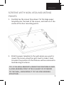
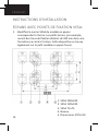
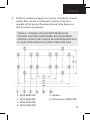
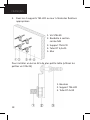
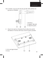
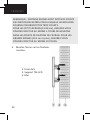
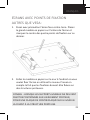
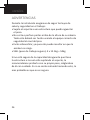
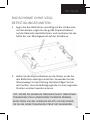
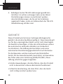
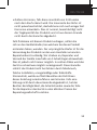
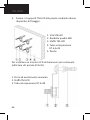
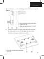
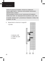
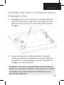
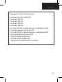
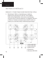
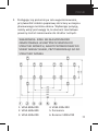
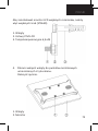
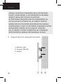
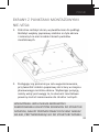
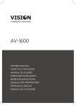
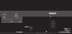
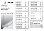
TM-LCD TECHMOUNT OWNERS MANUAL
TM-LCD TECHMOUNT GUIDE DE L’UTILISATEUR
TM-LCD TECHMOUNT MANUAL DE USUARIO
TM-LCD TECHMOUNT GEBRUIKERSHANDLEIDING
BEDIENUNGSANLEITUNG TM-LCD TECHMOUNT
TM-LCD TECHMOUNT MANUALE DEL PROPRIETARIO
TM-LCD TECHMOUNT: INSTRUKCJA OBSŁUGI
MANUAL DE UTILIZADOR DO TECHMOUNT TM-LCD
installation:innovation
ENGLISH
PROJECTOR TM-LCD TECHMOUNT
OWNERS MANUAL
Congratulations on your choice of the Vision TM-LCD
TECHMOUNT. In order to obtain the best performance please
be sure to read this owner’s manual and use your product
only in accordance with the instructions. An electronic
version of this manual and further information can be found
on www.visionaudiovisual.com
Vision is a partner in the TÜV SÜD product certification system. All
applicable certification is provided by TÜV. All products are designed
and imported into the EU by ‘Vision’ who is wholly owned by
‘Computer 2000 Distribution Ltd.’, Registered in England Nr. 01691472
at Hampshire House, Wade Road, Basingstoke, Hampshire RG24 8NE
WEE/AB0047SY
1
ENGLISH
WARNINGS
During installation take care to adhere to workplace health
and safety laws:
• Attach the bracket to a rated load-bearing structure.
• Do not cut or drill any parts above head height. This
should all be done using the correct safety equipment at
fl oor level.
• Avoid overstretching which might result in the ladder
tipping over.
• SWL (safe working load): 4 x 12.5kg = 50kg
If you are unsure about the load-bearing capacity of the
structure you are attaching the bracket to, we recommend
testing it with your body weight by hanging off it gently. If
you are uncomfortable doing this, it is probably not safe.
2
ENGLISH
Contents
4 x TM-LCD Wall Brackets
4 x M4×12 Finger Bolts
4 x M5×12 Finger Bolts
4 x M6×14 Finger Bolts
4 x M8×16 Finger Bolts
4 × ST8×50 Screws withM8 square washers
4 × RT expansion tube 6.5×45
4 × ST4×25 Screws with M4 square washers
4 × RT expansive tube 4×30
1 x Large Paper Template
1 x Small Paper Template
1 x Spirit Level with plastic clip
3
ENGLISH
INSTALLATION INSTRUCTIONS
Screens with VESA mounting points:
1. Identify VESA standard on the paper template that
matches the screen. For example, small screens will
have mounting holes 100mm x 100mm apart in a square
formation on the rear. This layout will be found on the
small paper template included.
4
1. VESA 200×100
2. VESA 100×100
3. VESA 75×75
4. Spirit Level
5. Size 297×210
0
0
ENGLISH
2. Stick the paper template to the wall where you want to
mount the screen using the spirit level to make it level.
Consider the position so that fixtures will be anchored to
load-bearing structures.
TIP: IF THE WALL BRACKETS CANNOT BE POSITIONED
OVER A LOAD-BEARING POINT ATTACH A SHEET OF
PLYWOOD TO THE WALL, ANCHORING IT TO THE
LOAD-BEARING STRUCTURE.
1. VESA 800×200
2. VESA 600×400
3. VESA 400×200
4. VESA 200×200
5. Spirit Level
6. Size 1000×700
5
ENGLISH
3. Attach the 4 x TM-LCD mounts to the wall using
appropriate fixtures.
1. ST8×50 Screw
2. M8 Square Washer
3. TM-LCD Bracket
4. RT expansion tube 6.5×45
5. Wall
To install smaller size LCD monitor (use ST4×25 small screws)
1. Finger Bolts
2. TM-LCD Bracket
3. RT expansion tube 4×30
6
ENGLISH
To install larger LCD monitor (user ST8×50 large screw)
45
1. Finger Bolts
2. TM-LCD Bracket
3. RT expansive tube 6.5×45
4. Using fingers screw 4 x finger bolts included into the
mounting points on the rear of screen. Turn until
finger-tight.
1. Finger Screws
2. Monitor
7
ENGLISH
NOTE: SOME SCREENS HAVE RECESSED MOUNTING
POINTS WHICH THE INCLUDED BOLTS MAY NOT BE LONG
ENOUGH TO REACH. FOR SMALL SCREENS (20-39”)
ENSURE YOU HAVE TURNED THE BOLTS INTO THE SCREEN
MOUNTING POINTS AT LEAST 5 TIMES. FOR LARGE
SCREENS (40”+) ENSURE YOU HAVE TURNED THE BOLTS AT
LEAST 10 TIMES.
5. Hang the screen on the wall mounts.
1. LCD monitor
2. TM-LCD bracket
3. Wall
8
ENGLISH
Screens with NON-VESA mounting
points:
1. Carefully lay the screen face-down. Put the large paper
template over the back of the screen, and mark on it the
centre of the four mounting points.
2. Stick the paper template to the wall where you want to
mount the screen using the spirit level to make it level.
Consider the position so that fixtures will be anchored to
load-bearing structures.
TIP: IF THE WALL BRACKETS CANNOT BE POSITIONED OVER
A LOAD-BEARING POINT ATTACH A SHEET OF PLYWOOD
TO THE WALL, ANCHORING IT TO THE LOAD-BEARING
STRUCTURE.
9
ENGLISH
3. Attach the 4 x TM-LCD mounts to the wall following the
steps 3-5 on the previous pages. The brackets should be
positioned so that the marks you made on the template
are visible at the bottom of the keyhole on the TM-LCD
wall mount.
WARRANTY
This product comes with a 2-year return to base warranty,
effective from the date of purchase. This warranty applies
only to the original purchaser and is not transferable. For the
avoidance of doubt, this will be taken from the information
held by the appointed national distributor at the point of
sale. The liability of the manufacturer and its appointed
service company is limited to the cost of repair and or
replacement of the faulty unit under warranty, except for
death or injury (EU85/374/EEC). This warranty protects you
against the following:
• Faulty wields resulting in the product not safely performing
its task within the recommended SWL (safe working load).
• Poor finishing resulting in the product not being able to be
assembled.
• External corrosion if identified within 24 hours of purchase.
The inside of the pipe is not powder-coated, so light
corrosion may develop over time. This is normal and does
not adversely affect the load-bearing capability of the
product, therefore it is not covered in this warranty.
10
ENGLISH
If you find you do have a problem with this product, you
should contact the AV reseller you purchased this product
from. The original purchaser is responsible for shipment of
the product to the manufacturer’s appointed service centre
for repair. We will endeavour to return repaired units within
5 working days, however this may not always be possible in
which case it will be returned as soon as practically possible.
This warranty does not protect this product against faults
caused by abuse, misuse, or incorrect installation which
might be caused by ignoring the guidelines set out in this
manual. If failure is not covered by this warranty, the owner
will be given the option to pay for labour and parts to repair
the unit at the service company’s standard rate.
11
ENGLISH
FRANÇAIS
12
FRANÇAIS
PROJECTOR TM-LCD TECHMOUNT
OWNERS MANUAL
Félicitations, vous venez d’acquérir la TECHMOUNT
PROJECTOR TM-LCD. Afi n d’obtenir la meilleure performance
possible, assurez-vous de vous conformer aux instructions
fournies dans le guide de l’utilisateur. Une version
électronique du guide et des informations complémentaires
sont disponibles sur notre site : www.visionaudiovisual.com
Vision est l’un des partenaires du système de certification produit
TÜV SÜD. Toutes les certifications pertinentes sont fournies par
TÜV. Tous les produits sont conçus et importés dans l’UE par Vision,
qui est une propriété exclusive de Computer 2000 Distribution Ltd.,
enregistrée au Royaume-Uni n° 01691472 Hampshire House, Wade
Road, Basingstoke, Hampshire RG24 8NE
WEE/AB0047SY
13
ENGLISH
FRANÇAIS
AVERTISSEMENTS
Pendant l’installation, veillez à suivre les règles de sécurité
suivantes:
• Attachez le support à une structure offi ciellement
capable de supporter une telle charge.
• Ne pas effectuer de perçage ni de découpage au dessus
du niveau de votre tête. Tou-jours les effectuer au sol en
utilisant le matériel adéquat.
• Evitez de trop vous étirer sur l’échelle, vous risqueriez de
vous renverser.
• Charge de Travail sans Danger (SWL) : 4 x 12.5kg = 50kg
Si vous n’êtes pas sûrs de la capacité de charge de votre
structure, nous vous recommendons un test au préalable
en utilisant votre propre poids corporel afi n d’en verifi er la
solidité. Si vous ne vous sentez pas confortable, la structure
n’est probablement pas adéquate.
14
FRANÇAIS
CONTENU
4 supports muraux TM-LCD
4 boulons M4×12
4 boulons M5×12
4 boulons M6×14
4 boulons M8×16
4 vis ST8×50 avec rondelles à section carrée M8
4 tubes RT 6,5×45
4 vis ST4×25 avec rondelles à section carrée M4
4 tubes RT 4×30
1 grand modèle en papier
1 petit modèle en papier
1 niveau avec clip en plastique
15
ENGLISH
FRANÇAIS
INSTRUCTIONS D’INSTALLATION
Écrans avec points de fixation VESA:
1. Identifiez la norme VESA du modèle en papier
correspondant à l’écran. Les petits écrans, par exemple,
auront des trous de fixation distants de 100 mm dans une
formation en carré à l’arrière. Cette disposition se trouve
également sur le petit modèle en papier fourni.
16
1. VESA 200×100
2. VESA 100×100
3. VESA 75×75
4. Niveau
5. Dimensions 297×210
FRANÇAIS
2. Collez le modèle en papier sur le mur à l’endroit où vous
voulez fixer l’écran en utilisant le niveau. Prenez en
compte le fait que les fixations doivent être fixées sur
des structures porteuses.
CONSEIL : LORSQUE LES SUPPORTS MURAUX NE
PEUVENT PAS ÊTRE POSITIONNÉS SUR UN ÉLÉMENT
PORTEUR, POSEZ UNE PLAQUE DE CONTREPLAQUÉ SUR
LE MUR EN LA FIXANT À LA STRUCTURE PORTEUSE.
1. VESA 800×200
2. VESA 600×400
3. VESA 400×200
4. VESA 200×200
5. Niveau
6. Dimensions 1000×700
17
ENGLISH
FRANÇAIS
3. Fixez les 4 supports TM-LCD au mur à l’aide des fixations
appropriées.
1. Vis ST8×50
2. Rondelle à section
carrée M8
3. Support TM-LCD
4. Tube RT 6,5×45
5. Mur
Pour installer un écran ACL de plus petite taille (utilisez les
petites vis ST4×25)
1. Boulons
2. Support TM-LCD
3. Tube RT 4×30
18
FRANÇAIS
Pour installer un écran ACL de plus grande taille (utilisez les
grandes vis ST8×50)
1. Boulons
2. Support TM-LCD
3. Tube RT 6,5×45
4. Vissez à la main les 4 boulons fournis dans les points
de fixation à l’arrière de l’écran. Serrez le plus possible.
D
1. Vis à serrage manuel
2. Écran
19
ENGLISH
FRANÇAIS
REMARQUE : CERTAINS ÉCRANS SONT DOTÉS DE POINTS
DE FIXATION ENCASTRÉS POUR LESQUELS LES BOULONS
FOURNIS POURRONT ÊTRE TROP COURTS.
POUR LES PETITS ÉCRANS (51-99 cm), ASSUREZ-VOUS
D’AVOIR EFFECTUÉ AU MOINS 5 TOURS DE BOULONS
DANS LES POINTS DE FIXATION DE L’ÉCRAN. POUR LES
GRANDS ÉCRANS (101 cm et plus), ASSUREZ-VOUS
D’AVOIR EFFECTUÉ AU MOINS 10 TOURS.
5. Montez l’écran sur les fixations
murales.
1. Écran ACL
2. Support TM-LCD
3. Mur
20
FRANÇAIS
Écrans avec points de fixation
autres que VESA:
1. Posez avec précaution l’écran face contre terre. Placez
le grand modèle en papier sur l’arrière de l’écran et
marquez le centre des quatre points de fixation sur ce
dernier.
2. Collez le modèle en papier sur le mur à l’endroit où vous
voulez fixer l’écran en utilisant le niveau. Prenez en
compte le fait que les fixations doivent être fixées sur
des structures porteuses.
CONSEIL : LORSQUE LES SUPPORTS MURAUX NE PEUVENT
PAS ÊTRE POSITIONNÉS SUR UN ÉLÉMENT PORTEUR,
POSEZ UNE PLAQUE DE CONTREPLAQUÉ SUR LE MUR EN
LA FIXANT À LA STRUCTURE PORTEUSE.
21
ENGLISH
FRANÇAIS
3. Fixez les supports TM-LCD au mur en suivant les étapes
3 à 5 décrites dans les pages précédentes. Les supports
doivent être positionnés de manière à ce que les
marques faites sur le modèle soient visibles dans le trou
de la fixation murale TM-LCD.
GARANTIE
Ce produit a une garantie de 2 ans qui prend effet le jour
de l’achat. Cette garantie concerne uniquement l’acheteur
initial et n’est pas transférable. Afi n d’éviter tout doute,
l’information référante sera celle du revendeur du lieu
d’achat. La responsabilité du fabricant et du revendeur est
limitée au coût de réparation et du remplacement de l’unité
sous garantie, excepté la mort ou des dommages (EU85/374/
EEC).La garantie vous protège contre:
• Fabrication défectueuse ayant pour effet une performance
non conforme au SWL (Norme de Travail Sans Danger).
• Fini de mauvaise qualité ayant pour conséquence une
impossibliité de montage.
• Corrosion externe si vous nous en notifi ez dans les 24h
suivant l’achat. L’intérieur du tuyau n’est pas poudré alors
une légère corrosion peut se développer à long terme. Ceci
est normal et ne devrait pas affecter la capacité de charde
du produit, ceci n’est donc pas couvert par la garantie.
22
FRANÇAIS
Si vous avez un problème avec ce produit, vous devez
contacter le revendeur. L’acheteur d’origine est responsable
de la livraison du produit au centre de service de réparation.
Nous ferons de notre possible pour vous retourner les unités
réparées sous 5 jours uvrables. Cependant, ceci n’est pas
toujours possible auquel cas nous nous engageons vous la
faire parvenir le plus rapidement possible. Cette garantie
ne protège pas l’unité ontre des défauts causés par abus,
mauvaise utilisation, installation incorrecte issus d’un
auvais suivi des conseils dans ce guide. i la faute n’est pas
couverte ci-dessus, l’acheteur aura le choix de payer pour la
reparation t les pièces requises aux prix standards établis par
le fabricant.
23
ENGLISH
Español
24
Español
PROJECTOR TM-LCD TECHMOUNT
MANUAL DE USUARIO
Flicidades por escoger este Vision PROJECTOR MT-LCD
TECHMOUNT.
Para obtener mejores resultados, por favor lea este manual,
y utilice este producto sólo de acuerdo con las instrucciones.
Una versión electrónica de este manual y más información se
puede encontrar en www.visionaudiovisual.com
Vision participa en el sistema de certificación de productos TÜV SÜD.
TÜV proporciona todas las certificaciones aplicables. Vision, sociedad
participada al 100% por Computer 2000 Distribution Ltd., registrada
en Inglaterra con el número 01691472 en Hampshire House, Wade
Road, Basingstoke, Hampshire RG24 8NE, diseña e importa todos los
productos a la UE.
WEE/AB0047SY
25
ENGLISH
Español
ADVERTENCIAS
Durante la instalación asegúrese de seguir las leyes de
salud y seguridad en el trabajo:
• Sujete el soporte a una estructura que pueda aguantar
el peso.
• No corte o perfore partes arriba de la altura de su cabeza.
Todo esto deberá ser hecho usando el equipo correcto de
seguridad al nivel del piso.
• Evite sobreestirar, ya que esto puede resultar en que la
escalera se caiga.
• SWL (peso de trabajo seguro): 4 x 12.5kg = 50kg
Si no está seguro de la capacidad de aguante que tiene
la estructura a la cual está sujetando el soporte, le
recomendamos probarlo con su propio peso, colgándose
de él con cuidado. Si no se siente cómodo haciendo esto, lo
mas probable es que no es seguro.
26
Español
CONTENIDO
4 soportes murales TM-LCD
4 pernos de orejetas M4x12
4 pernos de orejetas M5x12
4 pernos de orejetas M6x14
4 pernos de orejetas M8x16
4 tornillos ST8x50 con arandelas cuadradas M8
4 tubos de extensión RT 6,5x45
4 tornillos ST4x25 con arandelas cuadradas M4
4 tubos de extensión RT 4x30
1 plantilla de papel grande
1 plantilla de papel pequeña
1 nivel de burbuja con clip de plástico
27
ENGLISH
Español
INSTRUCCIONES DE INSTALACIÓN
Pantallas con puntos de montaje VESA:
1. Identifique el estándar VESA en la plantilla de papel
que coincide con la pantalla. Por ejemplo, las pantallas
pequeñas tendrán agujeros de montaje 100 mm x 100
mm separados en forma de cuadrado en la parte trasera.
Esta disposición se puede encontrar en la plantilla de
papel pequeña incluida.
28
1. VESA 200×100
2. VESA 100×100
3. VESA 75×75
4. Nivel de burbuja
5. Tamaño 297x210
ja
10
Español
2. Pegue la plantilla de papel a la pared en la cual quiere
montar la pantalla utilizando el nivel de burbuja para
que esté nivelada. Tenga en cuenta la posición, de
manera que los elementos estén anclados en estructuras
de carga.
CONSEJO: SI LOS SOPORTES MURALES NO PUEDEN
COLOCARSE EN UN PUNTO DE CARGA, SUJETE
UNA LÁMINA DE CONTRACHAPADO A LA PARED,
ANCLÁNDOLA A LA ESTRUCTURA DE CARGA.
1. VESA 800×200
2. VESA 600×400
3. VESA 400×200
4. VESA 200×200
5. Nivel de burbuja
6. Tamaño 1000×700
29
ENGLISH
Español
3. Sujete los 4 soportes TM-LCD a la pared utilizando los
elementos adecuados.
1. Tornillo ST8x50
2. Arandela cuadrada M8
3. Soporte TM-LCD
4. Tubo de extensión RT 6,5x45
5. Pared
Para instalar un monitor LCD de tamaño inferior (utilice
tornillos pequeños ST4x25)
1. Pernos de orejetas
2. Soporte TM-LCD
3. Tubo de extensión RT 4x30
30
Español
Para instalar un monitor LCD más grande (utilice tornillos
grandes ST8x50)
1. Pernos de orejetas
2. Soporte TM-LCD
3. Tubo de extensión
RT 6,5x45
5x45
4. Utilizando los dedos, atornille 4 pernos de orejetas
incluidos en los puntos de montaje de la parte trasera
de la pantalla. Gire hasta que estén apretados con la
mano.
30
1. Tornillos de orejetas
2. Monitor
31
ENGLISH
Español
NOTA: ALGUNAS PANTALLAS TIENEN PUNTOS DE MONTAJE
EMPOTRADOS Y LOS PERNOS INCLUIDOS PUEDEN NO SER
LO BASTANTE LARGOS PARA ALCANZARLOS.
PARA PANTALLAS PEQUEÑAS (20-39”) ASEGÚRESE DE QUE
HA GIRADO LOS PERNOS EN LOS PUNTOS DE MONTAJE DE
LA PANTALLA POR LO MENOS 5 VECES. PARA PANTALLAS
GRANDES (40”+) ASEGÚRESE DE QUE HA GIRADO LOS
PERNOS POR LO MENOS 10 VECES.
5. Cuelgue la pantalla de los montajes
murales.
1. Monitor LCD
2. Soporte TM-LCD
3. Pared
32
Español
Pantallas con puntos de montaje NO
VESA:
1. Coloque la pantalla con cuidado boca abajo. Coloque
la plantilla de papel grande sobre la parte trasera de la
pantalla y marque en ella el centro de los cuatro puntos
de montaje.
2. Pegue la plantilla de papel a la pared en la cual quiere
montar la pantalla utilizando el nivel de burbuja para que
esté nivelada. Tenga en cuenta la posición, de manera que
los elementos estén anclados en estructuras de carga.
CONSEJO: SI LOS SOPORTES MURALES NO PUEDEN
COLOCARSE EN UN PUNTO DE CARGA, SUJETE UNA
LÁMINA DE CONTRACHAPADO A LA PARED, ANCLÁNDOLA
A LA ESTRUCTURA DE CARGA.
33
ENGLISH
Español
3. Sujete los soportes 4 x TM-LCD a la pared siguiendo los
pasos 3-5 de las páginas anteriores. Los soportes deben
colocarse de forma que las marcas que ha hecho en la
plantilla sean visibles en la parte inferior de la bocallave
en el soporte mural TM-LCD.
GARANTIA
Este producto viene con una garantía de 2 años regreso
a base, efectivo desde la fecha de compra. La garantía se
aplica solamente al comprador original y no es transferible.
Para evitar cualquier duda, esto se tomará de la información
guardada por el distribuidor nacional al punto de venta. La
responsabilidad del fabricante y su compañía apuntada
está limitada al costo de reparación o el reemplazo del
producto defectuoso bajo garantía, a excepción de muerte o
de lesión (EU85/374/EEC). Esta garantía lo proteje
contra lo siguiente:
• Soldaduras defectuosas, provocando que el producto
no permita realizar la tarea requerida con el peso
recomendado para su uso de forma segura.
• Acabado pobre, resultando en no poderse montar
completamente el producto.
• Corrosión externa si se identifi ca en los primeros 21
días tras la compra. Si la parte interior del tuvo no está
recubierta de polvo, es posible que algo de corrosión se
34
Español
puede producir con el tiempo. No obstante, esto es normal
y no afecta a la capacidad de soportar el peso del producto.
Este hecho no está cubierto por esta garantía.
Si encuentra que tiene algún problema con este producto,
por favor contacte con el vendedor de Audio Visuales donde
lo compró. El comprador original es responsable por el envío
del producto al centro de servicio del fabricante para su
reparación. Nosotros procuraremos retornar las unidades
reparadas dentro de 5 días laborales, pero esto no siempre
será posible, en cual caso será retornado lo antes posible. La
garantía no protege a este producto contra averías causadas
por abuso, mal uso, instalación incorrecta, lo cual puede
ser causado por ignorar las indicaciones explicadas en este
manual. Si la avería no está cubierta por esta garantía, se le
dará al dueño la opción de pagar por el trabajo y las partes
necesarias para reparar la unidad, al precio estándar de la
compañía de servicio.
35
ENGLISH
Nederlands
36
Nederlands
PROJECTOR TM-LCD TECHMOUNT
GEBRUIKERSHANDLEIDING
Gefeliciteerd met uw aankoop van Vision PROJECTOR
TM-LCD TECHMOUNT.
Lees deze gebruikershandleiding en gebruik uw product
alleen in overeenstemming met de aanwijzingen voor een
optimale prestatie. U vindt een elektronische versie en
verdere informatie op: www.visionaudiovisual.com
Vision is een partner in het TÜV SÜD-productcertificeringssysteem.
Alle toepasselijke certificering wordt geleverd door TÜV. Alle
producten zijn ontworpen en in de EU geïmporteerd door ‘Vision’
dat volledig eigendom is van ‘Computer 2000 Distribution Ltd.’,
geregistreerd in Engeland nr. 01691472 op Hampshire House, Wade
Road, Basingstoke, Hampshire RG24 8NE
WEE/AB0047SY
37
ENGLISH
Nederlands
WAARSCHUWINGEN
Houd bij de installatie rekening met de gezondheids- en
veiligheidsvoorschriften
voor op de werkvloer:
• Bevestig de hendel aan een vaste gewichtdragende
structuur.
• Snijd of boor niet in plaatsen die zich boven uw hoofd
bevinden. Al deze werkzaamheden dienen uitgevoerd te
worden met de juiste veiligheidsuitrusting vlak boven de
vloer.
• Strek u niet te ver uit omdat de ladder dan kan
wegglijden.
• VWL (veilige werklading): 4 x 12.5kg = 50kg
Als u niet zeker bent van de draagkracht van de structuur
waaraan de hendel komt te hangen, is het raadzaam om
er eerst voorzichtig zelf aan te gaan hangen. Als u zich hier
niet prettig bij voelt, is het waarschijnlijk onveilig.
38
Nederlands
INHOUD
4 x TM-LCD-wandbeugels
4 x M4×12 vleugelbouten
4 x M5×12 vleugelbouten
4 x M6×12 vleugelbouten
4 x M8×12 vleugelbouten
4 × ST8×50 schroeven met M8 vierkante sluitringen
4 × RT-plug 6,5×45
4 × ST4×25 schroeven met M4 vierkante sluitringen
4 × RT-plug 4×30
1 x grote papieren sjabloon
1 x kleine papieren sjabloon
1 x waterpas met plastic clipje
39
ENGLISH
Nederlands
INSTALLATIE-INSTRUCTIES
Schermen met VESA-bevestigingspunten:
1. Zoek de VESA-standaard op de papieren sjabloon die
overeenkomt met het scherm. Een voorbeeld: kleine
schermen hebben bevestigingsgaten die 100mm x
100mm uit elkaar zijn verwijderd in een vierkant patroon
aan de achterzijde. Deze indeling is te vinden op de
kleine meegeleverde papieren sjabloon.
40
1. VESA 200×100
2. VESA 100×100
3. VESA 75×75
4. Waterpas
5. Grootte 297×210
Nederlands
2. Plak de papieren sjabloon aan de wand waar u het
scherm waterpas wilt bevestigen. Let op de positie
zodat de bouten op gewichtdragende plekken worden
aangebracht.
TIP: ALS DE WANDBEUGELS NIET OP EEN
GEWICHTDRAGEND PUNT KUNNEN WORDEN
AANGEBRACHT, BEVESTIG DAN EEN PLAAT MULTIPLEX
AAN DE WAND EN VERANKER DEZE AAN DE
GEWICHTDRAGENDE STRUCTUUR.
0
0
210
1. VESA 800×200
2. VESA 600×400
3. VESA 400×200
4. VESA 200×200
5. Waterpas
6. Grootte 1000×700
41
ENGLISH
Nederlands
3. Bevestig de 4 x TM-LCD-beugels met de juiste bouten
aan de wand.
1. ST8×50 schroef
2. M8 vierkante sluitring
3. TM-LCD-beugel
4. RT-plug 6,5×45
5. Wand
Een kleinere LCD-monitor installeren (gebruik ST4×25
kleine schroeven)
1. Vleugelbouten
2. TM-LCD-beugel
3. RT-plug 4×30
42
Nederlands
Een grotere LCD-monitor installeren (gebruik ST8×50
grote schroeven)
1. Vleugelbouten
2. TM-LCD-beugel
3. RT-plug 6,5×45
4. Draai 4 x meegeleverde vleugelbouten met de vingers
in de bevestigingspunten aan de achterzijde van het
scherm. Draai deze met de vingers aan tot deze vast
zitten.
1. Vleugelbouten
2. Monitor
43
ENGLISH
Nederlands
OPMERKING: BEPAALDE SCHERMEN HEBBEN VERZONKEN
BEVESTIGINGSPUNTEN, WAARDOOR DE MEEGELEVERDE
BOUTEN MOGELIJK NIET LANG GENOEG ZIJN.
ZORG ER BIJ KLEINE SCHERMEN VOOR (51CM – 100 CM)
DAT U DE BOUTEN IN DE SCHERMBEVESTIGINGSPUNTEN
MINIMAAL 5 KEER HEBT AANGEDRAAID. ZORG ER BIJ
GROTE SCHERMEN (101 CM OF MEER) VOOR DAT U DE
BOUTEN MINIMAAL 10 KEER HEBT AANGEDRAAID.
5. Hang de schermen op de wandhouders.
1. LCD-monitor
2. TM-LCD-beugel
3. Wand
44
Nederlands
Schermen met NON-VESAbevestigingspunten:
1. Leg de monitor voorzichtig met het scherm naar
beneden neer. Plaats de grote papieren sjabloon over
de achterzijde van het scherm en markeer daarop het
midden van de vier bevestigingspunten.
2. Plak de papieren sjabloon aan de wand waar u het
scherm waterpas wilt bevestigen. Let op de positie
zodat de bouten op gewichtdragende plekken worden
aangebracht.
TIP: ALS DE WANDBEUGELS NIET OP EEN
GEWICHTDRAGEND PUNT KUNNEN WORDEN
AANGEBRACHT, BEVESTIG DAN EEN PLAAT MULTIPLEX
AAN DE WAND EN VERANKER DEZE AAN DE
GEWICHTDRAGENDE STRUCTUUR.
45
ENGLISH
Nederlands
3. Bevestig de 4 x TM-LCD-beugels aan de wand aan de
hand van stap 3-5 op de vorige pagina’s. De beugels
dienen zodanig te worden geplaatst dat de markeringen
die u op de sjabloon hebt aangebracht onder het gat op
de TM-LCD-wandbeugel zichtbaar zijn.
GARANTIE
Dit product heeft een teruggeefgarantie van 2 jaar
beginnend bij de dag van aankoop. Deze garantie is alleen
geldig voor de koper en kan niet worden overgedragen.
Om enige twijfel te voorkomen, zal deze informatie niet
voorkomen op de informatie van de aangewezen nationale
distributeur op het verkooppunt. De aansprakelijkheid van
de abrikant en diens aangewezen servicebedrijf is beperkt
tot de reparatiekosten en/of vervanging van het gebreken
vertonende deel waarvoor deze garantie geldt, behalve in
geval van overlijden of letsel (EU85/374/EEC). Deze garantie
beschermt u tegen:
• Foutief gebruik waardoor het product niet veilig werkt
binnen de aanbevolen VWL (veilige werklading).
• Slechte afwerking waardoor het product niet gemonteerd
kan worden.
46
Nederlands
• Externe corrosie wanneer dit binnen 24 uur na aankoop
wordt vastgesteld. De binnenkant van de pijp is niet
gepoedercoat dus na verloop van tijd kan er lichte corrosie
ontstaan. Dit is normaal en zal de draagkracht van het
product niet negatief beïnvloeden, daarom valt dit niet
onder deze garantie.
Indien u toch een probleem met dit product ondervindt,
dient u contact op te nemen met de audiovisuele verkoper
bij wie u dit product kocht. De koper is verantwoordelijk
voor het transport van het product naar het reparerende
service centre aangewezen door de fabrikant. We proberen
de gerepareerde onderdelen binnen 5 werkdagen terug te
sturen. Dit is echter niet altijd mogelijk. In zo’n geval sturen
wij het gerepareerde onderdeel zo snel als de praktijk
dat toelaat terug. Deze garantie is ongeldig bij gebreken
veroorzaakt door misbruik, verkeerd gebruik of incorrecte
installatie die veroorzaakt kunnen zijn door het niet naleven
van de richtlijnen in deze handleiding. Indien het gebrek
niet door deze garantie wordt gedekt, heeft de eigenaar de
keuze om voor de werkuren en gerepareerde onderdelen te
betalen tegen het standaardtarief van het servicebedrijf.
47
ENGLISH
Deutsche
48
Deutsche
BEDIENUNGSANLEITUNG
PROJEKTOR TM-LCD TECHMOUNT
Herzlichen Glückwunsch zu Ihrer Wahl von Vision
PROJEKTOR TM-LCD TECHMOUNT. Um die beste Leistung zu
erzielen, sollten Sie diese Bedienungsanleitung lesen und das
Produkt nur entsprechend den Anweisungen verwenden.
Eine elektronische Ausgabe dieses Handbuchs sowie weitere
Informationen fi nden Sie unter www.visionaudiovisual.com
Vision ist ein Partnerunternehmen des TÜV SÜD
Produktzertifizierungssystems. Hierbei wurden alle Zertifizierungen
vom TÜV bereitgestellt. Alle Geräte werden von Vision entworfen
und in die EU eingeführt. Vision ist Eigentum von Computer 2000
Distribution Ltd., einem in England unter der Nummer 01691472
eingetragenen Unternehmen mit Niederlassung in Hampshire House,
Wade Road, Basingstoke, Hampshire RG24 8NE.
WEE/AB0047SY
49
ENGLISH
Deutsche
WARNUNG
Achten Sie bei der Installation darauf, die Vorschriften
bezüglich der Gesundheit am Arbeitsplatz und der
Sicherheit zu befolgen:
• Befestigen Sie die Halterung nur an einer bewerteten
tragenden Struktur.
• Schneiden oder bohren Sie keine Teile oberhalb der
Kopfhöhe an. All dies sollte am Boden mit der richtigen
Sicherheitsausrüstung erfolgen.
• Beugen Sie sich nicht zu weit vor, weil die Leiter
umkippen könnte.
• Zulässige Betriebslast: 4 x 12.5kg = 50kg
Falls Sie sich der Tragekapazität der Struktur, an welche
Sie die Halterung befestigen, nicht sicher sind, empfehlen
wir, diese vorsichtig durch Beanspruchung mit Ihrem
Körpergewicht zu prüfen. Falls Ihnen dies ungewiss
erscheint, ist es wahrscheinlich nicht ratsam.
50
Deutsche
INHALT
4 x TM-LCD Wandhalterungen
4 x M4×12 Fingerschrauben
4 x M5×12 Fingerschrauben
4 x M6×14 Fingerschrauben
4 x M8×16 Fingerschrauben
4 × ST8×50 Schrauben mit M8 Rechteckscheiben
4 × RT-Dübel 6,5×45
4 × ST4×25 Schrauben mit M4 Rechteckscheiben
4 × RT-Dübel 4×30
1 x Große Papierschablone
1 x Kleine Papierschablone
1 x Wasserwaage mit Kunststoffclip
51
ENGLISH
Deutsche
MONTAGEANLEITUNG
Bildschirme mit VESA-Befestigungspunkten:
1. Suchen Sie auf der Papierschablone die passende VESANorm für den Bildschirm. Beispielsweise haben kleine
Bildschirme Befestigungslöcher mit einem Abstand
von 100 mm x 100 mm in einer Rechteckanordnung.
Diese Anordnung finden Sie auf der beigefügten kleinen
Papierschablone.
52
1. VESA 200×100
2. VESA 100×100
3. VESA 75×75
4. Wasserwaage
5. Größe 297×210
Deutsche
2. Halten Sie die Papierschablone an die Wand, an der Sie
den Bildschirm anbringen möchten. Verwenden Sie die
Wasserwaage zur Ausrichtung. Berücksichtigen Sie bei
der Position, dass die Befestigungsteile in einer tragenden
Struktur verankert werden müssen.
TIPP: WENN DIE WANDHALTERUNGEN NICHT ÜBER
EINER TRAGENDEN STELLE ANGEORDNET WERDEN
KÖNNEN, BEFESTIGEN SIE EINE SPERRHOLZPLATTE AN
DER WAND, DIE SIE AN EINER TRAGENDEN STRUKTUR
VERANKERN.
0
0
10
1. VESA 800×200
2. VESA 600×400
3. VESA 400×200
4. VESA 200×200
5. Wasserwaage
6. Größe 1000×700
53
ENGLISH
Deutsche
3. Bringen Sie die 4 x TM-LCD-Halterungen mit dafür
geeigneten Befestigungen an der Wand an.
1. ST8×50 Schraube
2. M8 Rechteckscheibe
3. TM-LCD-Halter
4. RT-Dübel 6,5×45
5. Wand
Zur Montage kleinerer LCD-Bildschirme (kleine ST4×25Schrauben verwenden)
1. Fingerschrauben
2. TM-LCD-Halter
3. RT-Dübel 4×30
54
Deutsche
Zur Montage größerer LCD-Bildschirme (große ST8×50Schrauben verwenden)
1. Fingerschrauben
2. TM-LCD-Halter
3. RT-Dübel 6,5×45
4. Drehen Sie die mitgelieferten 4 Fingerschrauben mit den
Fingern in die Befestigungspunkte auf der Rückseite des
Bildschirms. Drehen Sie die Schrauben fingerfest.
en
r
1. Fingerschrauben
2. Bildschirm
55
ENGLISH
Deutsche
HINWEIS: EINIGE BILDSCHIRME HABEN VERSENKTE
BEFESTIGUNGSPUNKTE, IN DIE DIE MITGELIEFERTEN
SCHRAUBEN GGF. NICHT HINEINREICHEN.
STELLEN SIE BEI KLEINEN BILDSCHIRMEN (20-39”) SICHER,
DASS SIE DIE SCHRAUBEN MINDESTENS 5 DREHUNGEN IN
DIE BEFESTIGUNGSPUNKTE DES BILDSCHIRMS GEDREHT
HABEN. STELLEN SIE BEI GROSSEN BILDSCHIRMEN (>
40”) SICHER, DASS SIE DIE SCHRAUBEN MINDESTENS 10
DREHUNGEN EINGEDREHT HABEN.
5. Hängen Sie den Bildschirm in die
Wandhalterungen.
1. LCD-Bildschirm
2. TM-LCD-Halterung
3. Wand
56
Deutsche
Bildschirme ohne VESABefestigungspunkten:
1. Legen Sie den Bildschirm vorsichtig mit der Vorderseite
auf den Boden. Legen Sie die große Papierschablone
auf die Rückseite des Bildschirms und markieren Sie die
Mitte der vier Montagepunkt auf der Schablone.
2. Halten Sie die Papierschablone an die Wand, an der Sie
den Bildschirm anbringen möchten. Verwenden Sie die
Wasserwaage zur Ausrichtung. Berücksichtigen Sie bei
der Position, dass die Befestigungsteile in einer tragenden
Struktur verankert werden müssen.
TIPP: WENN DIE WANDHALTERUNGEN NICHT ÜBER EINER
TRAGENDEN STELLE ANGEORDNET WERDEN KÖNNEN,
BEFESTIGEN SIE EINE SPERRHOLZPLATTE AN DER WAND,
DIE SIE AN EINER TRAGENDEN STRUKTUR VERANKERN.
57
ENGLISH
Deutsche
3. Befestigen Sie die TM-LCD-Halterungen gemäß den
Schritten 3-5 auf der vorherigen Seite an der Wand.
Die Halterungen müssen so positioniert werden,
dass die Markierungen, die Sie auf der Schablone
angebracht haben, unten im Schlüsselloch der TM-LCDWandhalterung sichtbar sind.
GARANTIE
Dieses Produkt wird mit einer 2-jährigen Werksgarantie
geliefert, die ab dem Kaufdatum gültig ist. Diese Garantie gilt
nur für den ursprünglichen Käufer und ist nicht übertragbar.
Um Zweifel zu beseitigen, ist dies den Informationen seitens
des autorisierten nationalen Händlers am Verkaufsort
zu entnehmen. Die Haftung des Herstellers und seiner
autorisierten Dienstleistungsgesellschaft ist auf die Kosten
für die Reparatur und den Austausch des fehlerhaften
Geräts, für das Garantie besteht, beschränkt, mit Ausnahme
des Todes oder einer Verletzung (EU85/374/EEC). Diese
Haftung schützt Sie gegen Folgendes:
• Falsche Anwendungen, die dazu führen, dass das Produkt
nicht im Bereich der sicheren Betriebslast funktioniert .
• Schlechte Verarbeitung, die dazu führt, dass das Gerät
nicht richtig montiert werden kann.
58
ENGLISH
Deutsche
• Äußere Korrosion, falls diese innerhalb von 24 Stunden
nach dem Kauf erkannt wird. Die Innenseite des Rohrs ist
nicht pulverbeschichtet, deshalb kann sich nach einiger Zeit
Korrosion entwickeln. Dies ist normal, beeinträchtigt nicht
die Tragkapazität des Produkts und ist aus diesem Grunde
nicht durch die Garantie abgedeckt.
Falls Probleme mit diesem Produkt vorliegen, sollten Sie
sich an den Gerätehändler, bei welchem Sie dieses Produkt
erstanden haben, wenden. Der ursprüngliche Käufer ist für die
Versendung des Produkts an den vom Hersteller ernannten
Reparaturdienst zuständig. Wir streben an, Reparatur und
Versand der Geräte innerhalb von 5 Arbeitstagen abzuwickeln.
Dies ist jedoch nicht immer möglich. In solchen Fällen wird das
Gerät so schnell wie möglich zurückgesandt. Diese Garantie
schützt das Produkt nicht bei Fehlern durch Missbrauch,
falsche Installation, unregelmäßige oder fehlerhafte
Stromzufuhr, welche auf Nichtbeachten der Richtlinien
dieser Anleitung zurückzuführen sein könnten. Falls eine
Störung nicht durch diese Garantie abgedeckt ist, hat der
Besitzer die Möglichkeit, die Arbeitsstunden sowie die Teile
für die Reparatur des Geräts zu den üblichen Preisen der
Reparaturgesellschaft zu zahlen.
59
Italiano
ENGLISH
Italiano
PROJECTOR TM-LCD TECHMOUNT
MANUALE DEL PROPRIETARIO
Congratulazioni per aver scelto PROJECTOR TM-LCD
TECHMOUNT di Vision. Per ottenere la migliore prestazione,
leggere questo manuale del proprietario e usare il prodotto
secondo le istruzioni. E’ possible trovare una versione
elettronica di questo manuale e ulteriori informazioni su
www.visionaudiovisual.com
Vision aderisce al sistema di certificazione dei prodotti TÜV SÜD. Tutte
le certificazioni applicabili sono fornite da TÜV. Tutti i prodotti sono
progettati e importati in UE da Vision, società interamente controllata
da Computer 2000 Distribution Ltd, registrata in Inghilterra al n.
01691472 e avente sede legale in Hampshire House, Wade Road,
Basingstoke, Hampshire RG24 8NE
WEE/AB0047SY
61
ENGLISH
Italiano
AVVISI
Durante l’installazione attenersi alle leggi sulla salute e
sicurezza sul luogo di lavoro:
• Fissare il braccio ad una struttura portante ritenuta idonea.
• Non tagliare o forare nessuna parte al di sopra dell’altezza
della testa.
Queste operazioni devono essere eseguite tutte al
livello del pavimento usando l’attrezzatura di sicurezza
appropriata.
• Evitare di allungarsi troppo in quanto la scala potrebbe
ribaltarsi.
• SWL (safe working load: carico massimo di sicurezza):
4 x 12.5kg = 50kg
In caso di incertezza sulla capacità portante della struttura
a cui si sta fi ssando il braccio, è consigliabile testarla con il
peso del proprio corpo tirandola leggermente indietro. Se
nel farlo si avverte disagio, probabilmente non è sicura.
62
ENGLISH
Italiano
CONTENUTO
4 x Staffe a parete TM-LCD
4 x Perni ad avvitamento manuale M4×12
4 x Perni ad avvitamento manuale M5×12
4 x Perni ad avvitamento manuale M6×14
4 x Perni ad avvitamento manuale M8×16
4 x Viti ST8×50 con rondelle quadre M8
4 x Tubi ad espansione RT 6,5×45
4 x Viti ST4×25 con rondelle quadre M4
4 x Tubi ad espansione RT 4×30
1 x Dima di carta grande
1 x Dima di carta piccola
1 x Livella a bolla d’aria con clip di plastica
63
ENGLISH
Italiano
ISTRUZIONI DI MONTAGGIO
Schermi con punti di fissaggio VESA:
1. Identificare lo standard VESA sulla dima di carta
corrispondente allo schermo. Ad esempio, gli schermi
piccoli hanno fori di montaggio sul retro, disposti a
quadrato, distanziati di 100 mm. Questa disposizione si
trova sulla dima di carta piccola.
64
1. VESA 200×100
2. VESA 100×100
3. VESA 75×75
4. Livella a bolla d’aria
5. Dimensioni 297×210
ENGLISH
Italiano
2. Fissare la dima alla parete dove s’intende montare lo
schermo e livellarla con la livella. Valutare la posizione
in modo da poter ancorare i dispositivi di fissaggio a
strutture portanti.
CONSIGLIO: NEL CASO SIA IMPOSSIBILE POSIZIONARE
LA STAFFA SU UN PUNTO PORTANTE, APPLICARE
ALLA PARETE UN PANNELLO DI COMPENSATO
ANCORANDOLO ALLA STRUTTURA PORTANTE.
1. VESA 800×200
2. VESA 600×400
3. VESA 400×200
4. VESA 200×200
5. Livella a bolla d’aria
6. Dimensioni 1000×700
65
ENGLISH
Italiano
3. Fissare i 4 supporti TM-LCD alla parete mediante idonei
dispositivi di fissaggio.
1. Vite ST8×50
2. Rondella quadra M8
3. Staffa TM-LCD
4. Tubo ad espansione
RT 6,5×45
5. Parete
Per installare un monitor LCD di dimensioni più contenute
(utilizzare viti piccole ST4×25)
1. Perni ad avvitamento manuale
2. Staffa TM-LCD
3. Tubo ad espansione RT 4×30
66
ENGLISH
Italiano
Per installare un monitor LCD più grande (utilizzare viti grandi
ST8×50)
1. Perni ad avvitamento manuale
2. Staffa TM-LCD
3. Tubo ad espansione RT 6,5×45
4. Avvitare con le dita 4 perni ad avvitamento manuale
(in dotazione) nei punti di fissaggio sul retro dello
schermo. Stringere a fondo con le dita.
1. Perni ad avvitamento manuale
2. Monitor
67
ENGLISH
Italiano
NOTA: IN ALCUNI SCHERMI I PUNTI DI FISSAGGIO
SONO ARRETRATI E I PERNI IN DOTAZIONE NON SONO
ABBASTANZA LUNGHI.
PER SCHERMI PICCOLI (20-39”) BISOGNO STRINGERE I
PERNI NEI PUNTI DI FISSAGGIO PER ALMENO 5 GIRI. PER
SCHERMI GRANDI (40”+) BISOGNA STRINGERE I PERNI PER
ALMENO 10 GIRI.
5. Appendere lo schermo ai supporti
a parete.
1. Monitor LCD
2. Staffa TM-LCD
3. Parete
68
ENGLISH
Italiano
Schermi con punti di fissaggio NON A
STANDARD VESA:
1. Appoggiare con cura lo schermo con la parte anteriore
in basso. Posizionare la dima di carta grande sul retro
dello schermo e marcarvi il centro dei quatto punti di
fissaggio.
2. Fissare la dima di carta alla parete dove s’intende
montare lo schermo e livellarla con la livella. Valutare
la posizione in modo da poter ancorare i dispositivi di
fissaggio a strutture portanti.
CONSIGLIO: NEL CASO SIA IMPOSSIBILE POSIZIONARE LA
STAFFA SU UN PUNTO PORTANTE, APPLICARE ALLA PARETE
UN PANNELLO DI COMPENSATO ANCORANDOLO ALLA
STRUTTURA PORTANTE.
69
ENGLISH
Italiano
3. Fissare i supporti TM-LCD alla parete procedendo come
indicato nelle pagine precedenti ai punti 3-5. Le staffe
devono essere posizionate in modo che i riferimenti
tracciati sulla dima risultino visibili sul fondo del foro sul
supporto a parete del TM-LCD.
GARANZIA
Questo prodotto è dotato di una garanzia return to base
di 2 anni, valida dalla data dell’acquisto. Questa garanzia si
applica solo al primo compratore e non è cedibile. Allo scopo
di evitare qualsiasi dubbio, questi è colui che risulta tale dalle
informazioni raccolte presso il punto vendita dal distributore
nazionale assegnato. La responsabilità del produttore e
della società di servizi assegnata è limitata al costo della
riparazione e/o della sostituzione dell’unità difettosa in
garanzia, salvo i casi di morte o lesione (UE 85/374/CEE).
Questa garanzia la tutela contro quanto segue:
• Saldature difettose che impediscono al prodotto di
adempiere alla sua funzione in sicurezza entro il SWL
consigliato (safe working load: carico massimo di
sicurezza).
• Rifi nitura scadente che impedisce il montaggio del
prodotto.
70
ENGLISH
Italiano
• Corrosione esterna se identifi cata entro 24 ore
dall’acquisto. L’interno del tubo non è rivestito a polvere,
pertanto può svilupparsi una leggera corrosione nel
tempo. Si tratta di un fenomeno normale che non incide
negativamente sulla capacità portante del prodotto,
pertanto non è coperto da questa garanzia.
Qualora ritenga di avere un problema con questo prodotto,
contatti il rivenditore di AV presso cui ha effettuato
l’acquisto. Il primo acquirente è responsabile della
spedizione del prodotto al centro assistenza del produttore
per la riparazione. Sarà compiuto il massimo sforzo per
restituire le unità riparate entro 5 giorni lavorativi, per
quanto questo non sempre è possibile, nel qual caso la
restituzione avverrà al più presto. Questa garanzia non
protegge il prodotto contro i guasti provocati da abuso, uso
improprio o installazione non corretta che possa essere
causato dalla mancata conoscenza delle line guida esposte in
questo manuale.
Qualora il guasto non sia coperto da questa garanzia,
al proprietario sarà offerta la possibilità di pagare la
manodopera e le parti di ricambio per riparare l’unità alla
tariffa standard richiesta dalla società di assistenza.
71
POLSKI
ENGLISH
POLSKI
PROJECTOR TM-LCD TECHMOUNT:
INSTRUKCJA OBSŁUGI
Gratulujemy wyboru uchwytu do projektorów Vision
PROJECTOR TM-LCD TECHMOUNT. Aby móc w pełni
wykorzystać możliwości tego produktu, należy koniecznie
przeczytać niniejszą instrukcję obsługi i używać go wyłącznie
zgodnie z zawartymi w niej zaleceniami. Elektroniczna wersja
tej instrukcji i inne informacje są dostępne pod adresem
www.visionaudiovisual.com
Vision jest partnerem w systemie certyfikacji produktów TÜV SÜD.
TÜV zapewnia wszystkie odpowiednie certyfikaty. Wszystkie produkty
są zaprojektowane z myślą o krajach Unii Europejskiej i importowane
do nich przez firmę „Vision” należącą w całości do „Computer 2000
Distribution Ltd.”, spółki zarejestrowanej w Anglii pod numerem
01691472 w Hampshire House, Wade Road, Basingstoke, Hampshire
RG24 8NE.
WEE/AB0047SY
73
ENGLISH
POLSKI
OSTRZEŻENIA
Przy instalowaniu uchwytu należy przestrzegać
obowiązujących przepisów bezpieczeństwa i higieny pracy:
• Uchwyt wolno zainstalować wyłącznie na konstrukcji
nośnej o znanym udźwigu.
• Nie wolno wykonywać cięć ani nawiertów w częściach
znajdujących się na wysokości przekraczającej wzrost osoby
instalującej produkt. Tego rodzaju prace powinny być
wykonywane na części bezpiecznie ułożonej na podłożu i
przy użyciu odpowiedniego wyposażenia ochronnego.
• W przypadku pracy na drabinie, nie wolno nadmiernie
wychylać się w żadną stronę, gdyż grozi to przewróceniem
drabiny.
• Dopuszczalne obciążenie robocze: 4 x 12.5kg = 50kg
W przypadku niepewności co do wytrzymałości struktury, do
której ma być przymocowany uchwyt, zalecamy sprawdzenie
jej udźwigu za pomocą własnej masy ciała przez ostrożne
zawieszenie się na niej. Jeżeli nie daje ona poczucia
bezpieczeństwa osobie sprawdzającej jej wytrzymałość, nie
zapewni go też najprawdopodobniej produktowi.
74
ENGLISH
POLSKI
ZAWARTOŚĆ ZESTAWU
4 x uchwyty ścienne TM-LCD
4 x wkręty M4×12
4 x wkręty M5×12
4 x wkręty M6×14
4 x wkręty M8×16
4 x śruby ST8×50 z kwadratowymi podkładkami M8
4 x tuleje kompensacyjne 6,5×45
4 x śruby ST8×25 z kwadratowymi podkładkami M8
4 x tuleje kompensacyjne 4×30
1 x duży szablon papierowy
1 x mały szablon papierowy
1 x poziomica z plastikowym zaciskiem
75
ENGLISH
POLSKI
INSTRUKCJA INSTALACJI
Ekrany z punktami montażowymi VESA:
1. Zlokalizować VESA na standardowym szablonie
papierowym pasującym do ekranu. Na przykład,
małe ekrany będą miały z tyłu otwory montażowe,
rozmieszczone w formie kwadratu, w odległości 100 mm
x 100 mm. Poniższe rozmieszczenie znaleźć można na
zawartym w zestawie małym szablonie papierowym.
76
1. VESA 200×100
2. VESA 100×100
3. VESA 75×75
4. Poziomica
5. Rozmiar 297×210
10
ENGLISH
POLSKI
2. Posługując się poziomicą w celu wypoziomowania,
przytwierdzić szablon papierowy do ściany w miejscu
planowanego montażu ekranu. Wybierając pozycję,
należy wziąć pod uwagę to, że element montażowe
powinny zostać zamocowane do struktur nośnych.
WSKAZÓWKA: JEŻELI NIE MA MOŻLIWOŚCI
ZAMOCOWANIA UCHWYTÓW ŚCIENNYCH DO
STRUKTUR NOŚNYCH, NALEŻY PRZYMOCOWAĆ DO
ŚCIANY ARKUSZ SKLEJKI, PRZYTWIERDZAJĄC GO DO
STRUKTURY NOŚNEJ.
1. VESA 800×200
2. VESA 600×400
3. VESA 400×200
4. VESA 200×200
5. Poziomica
6. Rozmiar 1000×700
77
ENGLISH
POLSKI
3. Za pomocą odpowiednich elementów montażowych,
zamontować 4 x uchwyty TM-LCD do ściany.
1. Śruba ST8×50
2. Podkładka kwadratowa M8
3. Uchwyt TM-LCD
4. Tuleja kompensacyjna
6,5×45
5. Ściana
Aby zainstalować monitor LCD mniejszych rozmiarów, należy
użyć mniejszych śrub (ST4x25)
1. Wkręty
2. Uchwyt TM-LCD
3. Tuleja kompensacyjna 4×30
78
ENGLISH
POLSKI
Aby zainstalować monitor LCD większych rozmiarów, należy
użyć większych śrub (ST8x50)
1. Wkręty
2. Uchwyt TM-LCD
3. Tuleja kompensacyjna 6,5×45
4. Palcami wkręcić wkręty do punktów montażowych
umieszczonych z tyłu ekranu.
Dokręcić ręcznie.
1. Wkręty
2. Monitor
79
ENGLISH
POLSKI
UWAGA: NIEKTÓRE Z EKRANÓW MAJĄ WPUSZCZANE
PUNKTY MONTAŻOWE, A DOSTARCZONE W ZESTAWIE
WKRĘTY MOGĄ BYĆ DO NICH ZA KRÓTKIE.
W PRZYPADKU EKRANÓW MAŁYCH ROZMIARÓW (2039 CALI) NALEŻY UPEWNIĆ SIĘ, ŻE WKRĘTY ZOSTAŁY
WKRĘCONE DO OTWORÓW MONTAŻOWYCH EKRANU
PRZYNAJMNIEJ 5 RAZY. W PRZYPADKU EKRANÓW DUŻYCH
ROZMIARÓW (PONAD 40 CALI) NALEŻY UPEWNIĆ
SIĘ, ŻE WKRĘTY ZOSTAŁY WKRĘCONE DO OTWORÓW
MONTAŻOWYCH EKRANU PRZYNAJMNIEJ 10 RAZY.
5. Powiesić ekran na uchwytach ściennych.
1. Monitor LCD
2. Uchwyt TM-LCD
3. Ściana
80
ENGLISH
POLSKI
Ekrany z punktami montażowymi
NIE-VESA:
1. Ostrożnie rozłożyć ekran, wyświetlaczem do podłogi.
Rozłożyć większy papierowy szablon na tyle ekranu
i zaznaczyć na nim środek czterech punktów
montażowych.
2. Posługując się poziomicą w celu wypoziomowania,
przytwierdzić szablon papierowy do ściany w miejscu
planowanego montażu ekranu. Wybierając pozycję,
należy wziąć pod uwagę to, że element montażowe
powinny zostać zamocowane do struktur nośnych.
WSKAZÓWKA: JEŻELI NIE MA MOŻLIWOŚCI
ZAMOCOWANIA UCHWYTÓW ŚCIENNYCH DO STRUKTUR
NOŚNYCH, NALEŻY PRZYMOCOWAĆ DO ŚCIANY ARKUSZ
SKLEJKI, PRZYTWIERDZAJĄC GO DO STRUKTURY NOŚNEJ.
81
ENGLISH
POLSKI
3. Przymocować uchwyty TM-LCD do ściany i powtórzyć
kroki 3-5 opisane na poprzednich stronach. Uchwyty
należy rozmieścić tak, aby oznaczenia wykonane na
szablonie były widoczne na spodzie otworu uchwytu
TM-LCD.
GWARANCJA
Niniejszy produkt jest objęty 2-letnią gwarancją typu
Return to Base (naprawa w punkcie serwisowym), o okresie
biegnącym od daty zakupu. Gwarancja ta przysługuje
tylko pierwszemu nabywcy i jest nieprzenośna. W celu
uniknięcia nieporozumień, tożsamość pierwszego nabywcy
jest określana na podstawie ewidencji prowadzonej przez
wyznaczonego dystrybutora w kraju zakupu produktu.
Odpowiedzialność producenta i wyznaczonego przez niego
dostawcy usług serwisowych z tytułu niniejszej gwarancji
jest ograniczona do wysokości kosztu naprawy lub wymiany
wadliwego produktu, za wyjątkiem przypadków poniesionej
przez konsumenta śmierci lub obrażeń (dyrektywa 85/374/
EWG). Niniejsza gwarancja chroni nabywcę w zakresie:
• niezdolności produktu do bezpiecznego pełnienia swojej
funkcji przy obciążeniu nie przekraczającym zalecanego
przez producenta dopuszczalnego obciążenia roboczego,
• wad wykończenia, uniemożliwiających złożenie produktu,
• korozji zewnętrznych powierzchni produktu, o ile
zostanie stwierdzona w ciągu 24 godzin od zakupu.
82
ENGLISH
POLSKI
Wnętrze elementów rurowych nie zostało powleczone
powłoką proszkową, z czasem może więc pojawić się na
tej powierzchni lekka warstwa korozji. Jest to zjawisko
normalne i nie ma wpływu na udźwig produktu, w związku
z czym nie jest też objęte niniejszą gwarancją.
W przypadku jakichkolwiek problemów z produktem należy
skontaktować się ze sprzedawcą sprzętu audio-wideo, u
którego został on nabyty. Sprzedawca będzie wówczas
odpowiedzialny za przesłanie produktu do autoryzowanego
przez producenta punktu serwisowego w celu dokonania
naprawy.
Producent dołoży starań, aby naprawiony produkt został
zwrócony w ciągu 5 dni roboczych, może to jednak w
niektórych przypadkach nie być wykonalne i jego zwrot
nastąpi wówczas później, w najwcześniejszym możliwym
terminie. Niniejsza gwarancja nie chroni konsumenta
przed wadami produktu, spowodowanymi świadomym
lub nieświadomym użyciem produktu niezgodnie z
przeznaczeniem, bądź nieprawidłowo przeprowadzoną
instalacją. Wady takie mogą wyniknąć z niezastosowania się
do wytycznych zawartych w tej instrukcji.
W takim przypadku właściciel produktu otrzyma możliwość
dokonania zapłaty za wykonawstwo i części, co umożliwi
naprawienie sprzętu po standardowych stawkach
stosowanych przez firmę oferującą autoryzowane przez
producenta usługi serwisowe.
83
Português
ENGLISH
Português
MANUAL DE UTILIZADOR DO
TECHMOUNT TM-LCD
Parabéns pela sua escolha do Vision TECHMOUNT TMLCD. Para obter o melhor desempenho, leia este manual e
utilize o seu produto apenas de acordo com as instruções
apresentadas. Pode obter uma versão digital deste manual,
assim como informações adicionais, em
www.visionaudiovisual.com
A Vision é um dos parceiros do sistema de certificação de produtos
TÜV SÜD. Todas as certificações aplicáveis são fornecidas pela
TÜV. Todos os produtos são concebidos e importados para a União
Europeia pela ‘Vision’, propriedade integral da ‘Computer 2000
Distribution Ltd.’, registada em Inglaterra com o nº. 01691472 em
Hampshire House, Wade Road, Basingstoke, Hampshire RG24 8NE
WEE/AB0047SY
85
ENGLISH
Português
AVISOS
Durante a instalação, tenha cuidado de respeitar as leis de
higiene e segurança no trabalho:
• Prenda o suporte numa estrutura de suporte de carga
adequada.
• Não corte ou perfure quaisquer peças elevadas acima
da altura da cabeça. Isto deve ser feito ao nível do solo,
com o equipamento de segurança adequado.
• Evite esticar-se demasiado, o que pode resultar em
voltar a escada.
• Carga de trabalho segura: 4 x 12.5 kg = 50 kg
Se não estiver seguro da capacidade de carga da estrutura
à qual está a prender o suporte, recomendamos que
a teste, suportando o peso do seu corpo levemente
sobre a mesma. Se não estiver confortável ao fazê-lo,
provavelmente não é seguro.
86
ENGLISH
Português
CONTEÚDOS
4 x Suportes de parede TM-LCD
4 x Parafusos manuais M4×12
4 x Parafusos manuais M5×12
4 x Parafusos manuais M6×14
4 x Parafusos manuais M8×16
4 × Parafusos ST8×50 anilhas quadradas M8
4 × Tubo de expansão RT 6,5×45
4 × Parafusos ST4×25 com anilhas quadradas M4
4 × Tubo de expansão RT 4×30
1 x Modelo de papel grande
1 x Modelo de papel pequeno
1 x Nível com braçadeira plástica
87
ENGLISH
Português
INSTRUÇÕES DE INSTALAÇÃO
ECRÃS COM PONTOS DE FIXAÇÃO VESA:
1. Identifique a norma VESA correspondente ao ecrã no
modelo de papel. Por exemplo, os ecrãs pequenos têm
orifícios de fixação de 100 em 100 mm, numa formação
quadrada na parte de trás. Esta disposição pode ser
encontrada no modelo de papel pequeno incluído.
88
1. VESA 200×100
2. VESA 100×100
3. VESA 75×75
4. Nível
5. Tamanho 297×210
210
ENGLISH
Português
2. Cole o modelo de papel na parede no ponto em
que pretende montar o ecrã, utilizando o nível para
assegurar o alinhamento. Considere a posição de modo
a que as fixações sejam presas a estruturas de suporte
de carga.
DICA: SE OS SUPORTE DE PAREDE NÃO PODEM SER
POSICIONADOS SOBRE UM PONTO DE SUPORTE DE
CARGA, PRENDA UMA PLACA DE MADEIRA À PAREDE,
FIXANDO-A À ESTRUTURA DE SUPORTE DE CARGA.
1. VESA 800×200
2. VESA 600×400
3. VESA 400×200
4. VESA 200×200
5. Nível
6. Tamanho 1000×700
89
ENGLISH
Português
3. Prenda os 4 suportes TM-LCD à parede utilizando
fixações adequadas.
1. Parafuso ST8×50
2. Anilha quadrada M8
3. Suporte TM-LCD
4. Tubo de expansão
RT 6,5×45
5. Parede
Para instalar um monitor LCD de dimensões mais
pequenas (utilize parafusos pequenos ST4x25)
1. Parafusos manuais
2. Suporte TM-LCD
3. Tubo de expansão RT 4×30
90
ENGLISH
Português
Para instalar um monitor LCD de dimensões maiores (utilize
parafusos grandes ST8x50)
1. Parafusos manuais
2. Suporte TM-LCD
3. Tubo de expansão RT 6,5×45
4. Aperte manualmente os 4 parafusos incluídos, nos
pontos de fixação na parte traseira do ecrã. Aperte até
não ser possível apertar mais manualmente.
1. Parafusos manuais
2. Monitor
91
ENGLISH
Português
NOTA: ALGUNS ECRÃS TÊM PONTOS DE FIXAÇÃO
RECUADOS, PARA OS QUAIS OS PARAFUSOS INCLUÍDOS
PODEM NÃO TER COMPRIMENTO SUFICIENTE.
PARA ECRÃS PEQUENOS (20 A 39”), CERTIFIQUE-SE DE
QUE RODOU OS PARAFUSOS NOS PONTOS DE FIXAÇÃO DO
ECRÃ PELO MENOS 5 VEZES. PARA ECRÃS MAIORES (+ DE
40”), CERTIFIQUE-SE DE QUE RODOU OS PARAFUSOS PELO
MENOS 10 VEZES.
5. Pendure o ecrã no suporte de parede.
1. Monitor LCD
2. Suporte TM-LCD
3. Parede
92
ENGLISH
Português
ECRÃS COM PONTOS DE FIXAÇÃO
NÃO-VESA:
1. Volte o ecrã para baixo com cuidado. Coloque o modelo
de papel grande sobre a parte traseira do ecrã e marque
o centro dos quatro parafusos de fixação.
2. Cole o modelo de papel na parede no ponto em que
pretende montar o ecrã, utilizando o nível para assegurar
o alinhamento. Considere a posição de modo a que as
fixações sejam presas a estruturas de suporte de carga.
DICA: SE OS SUPORTE DE PAREDE NÃO PODEM SER
POSICIONADOS SOBRE UM PONTO DE SUPORTE DE
CARGA, PRENDA UMA PLACA DE MADEIRA À PAREDE,
FIXANDO-A À ESTRUTURA DE SUPORTE DE CARGA.
93
ENGLISH
Português
3. Prenda os 4 suportes TM-LCD na parede seguindo os
passos 3 a 5 nas páginas anteriores. Os suportes devem
ser posicionados de modo a que as marcas no modelo
sejam visíveis no fundo do orifício no suporte de parede
TM-LCD.
GARANTIA
Este produto tem uma garantia de 2 anos, com efeito a
partir da data de compra. Esta garantia aplica-se apenas ao
comprador original e não é transferível. Para evitar dúvidas,
a garantia será aplicada à informação retida pelo distribuidor
nacional designado no ponto de venda. A responsabilidade
do fabricante e da empresa de assistência designada limitase ao custo de reparação e/ou substituição da unidade
avariada ao abrigo da garantia, excepto por morte ou
ferimentos (EU85/374/CEE). Esta garantia protege-o nas
seguintes situações:
• Fixações defeituosas, resultando na incapacidade do
produto de desempenhar a sua função de forma segura
dentro da carga de trabalho recomendada.
• Fraco acabamento resultando na incapacidade de montar
o produto.
• Corrosão externa se identificada dentro de 24 horas após a
compra. A parte interior do tubo não é revestida, pelo que
94
ENGLISH
Português
pode desenvolver corrosão leve. Isto é normal e não afecta
adversamente a capacidade de carga do produto; como tal
não é abrangida por esta garantia.
Se encontrar qualquer problema neste produto, deve
contactar o revendedor de equipamento A/V ao qual
adquiriu o produto. O comprador original é responsável pelo
envio do produto para reparação para o centro de assistência
designado pelo fabricante. Faremos o nosso melhor para
devolver unidades reparadas dentro de 5 úteis. Contudo,
isso pode não ser sempre possível, sendo que a unidade
será devolvida o mais rapidamente possível. A garantia não
protege este produto contra avarias provocadas por abuso,
utilização incorrecta ou instalação incorrecta, que possam
ser provocadas pelo desrespeito das linhas de orientação
definidas neste manual. Se a avaria não for abrangida por
esta garantia, será dada ao proprietário a opção de pagar a
mão-de-obra e peças necessárias para reparar a unidade,
com a tarifa normal da empresa de assistência.
95