1
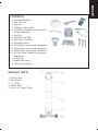
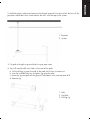
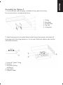
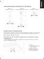
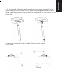
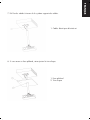
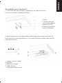
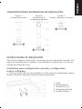
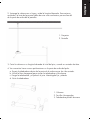
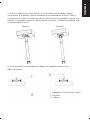
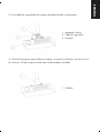
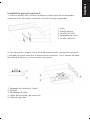
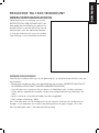
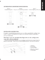
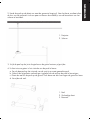
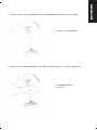
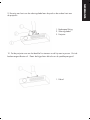
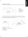
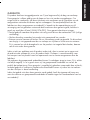
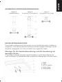
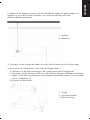
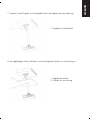
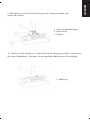
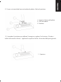
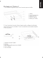
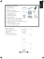
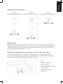
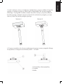
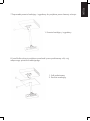
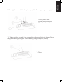
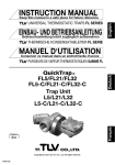
ENGLISH
TM-UST TECHMOUNT OWNERS MANUAL
TM-UST TECHMOUNT GUIDE DE L’UTILISATEUR
TM-UST TECHMOUNT MANUAL DE USUARIO
TM-UST TECHMOUNT GEBRUIKERSHANDLEIDING
BEDIENUNGSANLEITUNG TM-UST TECHMOUNT
TM-UST TECHMOUNT MANUALE DEL PROPRIETARIO TM-UST
PROJECTOR TM-1200 TECHMOUNT: INSTRUKCJA OBSŁUGI
installation:innovation
Congratulations on your choice of the Vision
PROJECTOR TM-1200 TECHMOUNT. In
order to obtain the best performance please
be sure to read this owner’s manual and
use your product only in accordance with
the instructions. An electronic version of this
manual and further information can be found
on www.visionaudiovisual.com
WARNINGS
During installation take care to adhere to workplace health and safety laws:
• Attach the bracket to a rated load-bearing structure. NEVER MOUNT CAGE OR
BRACKET DIRECTLY TO A FALSE CEILING!
• Do not cut or drill any parts above head height. This should all be done using the correct safety equipment at floor level.
• Avoid overstretching which might result in the ladder tipping over.
• SWL (safe working load): 20kg
If you are unsure about the load-bearing capacity of the structure you are attaching the
bracket to, we recommend testing it with your body weight by hanging off it gently. If you
are uncomfortable doing this, it is probably not safe.
ENGLISH
PROJECTOR TM-1200 TECHMOUNT OWNERS MANUAL
1
1
1
1
4
x
x
x
x
x
1
4
4
4
4
4
4
4
x
x
x
x
x
x
x
x
1x
1x
1x
Assembled Bracket
Pole Trim Disk
Spanner
Fall-arrest safety cable
M10 bolts with plastic rawl plugs for
ceiling attachment
Hex Key
M8x8 Pin Hex Bolts
M8x14 Pin Hex Bolts
Threaded sleeves
M5x43 bolts for projector attachment
M4x43 bolts for projector attachment
M3x43 bolts for projector attachment
M2.5x43 pan slot bolts for projector
attachment
Drilling jig
Bottom yoke cover
Tilting top mechanism
BRACKET PARTS
1.
2.
3.
4.
5.
Ceiling Yoke
Top Coupler
1.1m Pole
Bottom Yoke
Universal “Spider”Fitting
ENGLISH
CONTENTS
ENGLISH
ALTERNATIVE ASSEMBLY CONFIGURATIONS:
Option A
Standard configuration
Option B
Option C
Sloped ceiling fitting installed Close-coupled without a pole
INSTALLATION INSTRUCTIONS
To make installation quick and easy, this product has already been partially assembled.
This bracket is designed to be modular, and interchange with brackets that use the same 2”
(51mm) pole standard.
Assembly for the standard configuration and sloped ceiling
configuration:
1. Use the M8 bolts and Rawl plugs included to fix top yoke to the ceiling. For concrete
ceilings use appropriate fixings.
1.
2.
3.
4.
5.
Ceiling
Rawl plug
M10x25 Bolt
Top Yoke
Ceiling bolt
1. Projector
2. Screen
3. Cut pole to length at ground level using a pipe cutter.
4. You will need to drill new holes in the end of the pole:
a. Fit the drilling jig onto the end of the pole which has just been cut.
b. Use the included Hex key to tighten jig onto the pole.
c. Place the jig and pole on the ground. Hold down with one foot and drill.
d. Remove jig.
1. Pole
2. Hex Bolt
3. Drilling jig
ENGLISH
2. Hold the pole in place and measure the length required. For best results the lens of the
projector should be a few inches above the axis with the top of the screen.
6. Attach the projector to the spider/bottom yoke fitting to the projector,
and attach all to the pole.
1. Universal “Spider” Fitting
2. Projector
3. Pole
ENGLISH
5. For the standard configuration attach the pole to the top coupler, then attach the top
coupler directly to the ceiling yoke. For the sloped ceiling configuration attach the pole to
the top coupler, then connect the top coupler to the tilting mechanism, then connect all to the
ceiling yoke.
Option A:
Option B:
1. Input and Power Cables
8. If you have a false ceiling, fit the included trim disk.
1. False Ceiling
2. Trim Disk
ENGLISH
7. Thread the input and power cables through the bracket’s cable management system.
1. Bottom pole fitting
2. Fall-arrest cable
3. Projector
10. Turn the projector on to calibrate image and adjust tilt. Lock off bottom yoke bolts. Fit
the included cover over the swivel yoke.
1. Cover
ENGLISH
9. Fix one end of fall-arrest cable to pole, and the other end to projector.
ENGLISH
Assembly for Option C
1. Use the M8 bolts and Rawl plugs included to fix top yoke to the ceiling.
For concrete ceilings use appropriate fixings.
1.
2.
3.
4.
5.
Ceiling
Rawl plugs
M10x25 Bolt
Top Yoke
Ceiling bolt
2. Attach the projector to the spider/bottom yoke fitting to the projector, and attach all
to the top piece of the tilting mechanism. Fix one end of fall-arrest cable to pole, and the
other end to projector.
1. Universal “Spider” Fitting
2. Projector
3. Top piece of tilting
mechanism
4. Input cables
5. Fall-arrest cable
This product comes with a 2-year return to base warranty, effective from the date of
purchase. This warranty applies only to the original purchaser and is not transferable.
For the avoidance of doubt, this will be taken from the information held by the appointed
national distributor at the point of sale. The liability of the manufacturer and its appointed
service company is limited to the cost of repair and or replacement of the faulty unit under
warranty, except for death or injury (EU85/374/EEC). This warranty protects you against
the following:
• Faulty wields resulting in the product not safely performing its task within the recommended
SWL (safe working load).
• Poor finishing resulting in the product not being able to be assembled.
• External corrosion if identified within 24 hours of purchase. The inside of the pipe is not
powder-coated, so light corrosion may develop over time. This is normal and does not
adversely affect the load-bearing capability of the product, therefore it is not covered in
this warranty.
If you find you do have a problem with this product, you should contact the AV reseller
you purchased this product from. The original purchaser is responsible for shipment of the
product to the manufacturer’s appointed service centre for repair.
We will endeavour to return repaired units within 5 working days, however this may not
always be possible in which case it will be returned as soon as practically possible. This
warranty does not protect this product against faults caused by abuse, misuse, or incorrect
installation which might be caused by ignoring the guidelines set out in this manual.
If failure is not covered by this warranty, the owner will be given the option to pay for labour
and parts to repair the unit at the service company’s standard rate.
ENGLISH
WARRANTY
Félicitations, vous venez d’acquérir la
TECHMOUNT PROJECTOR TM-1200 .
Afin d’obtenir la meilleure performance
possible, assurez-vous de vous conformer
aux instructions fournies dans le guide de
l’utilisateur. Une version électronique du
guide et des informations complémentaires
sont disponibles sur notre site : www.
visionaudiovisual.com
AVERTISSEMENTS
Pendant l’installation, veillez à suivre les règles de sécurité suivantes:
• Attachez le support à une structure officiellement capable de supporter une telle
charge. NE JAMAIS MONTER LA CAGE OU LE SUPPORT A UN FAUX PLAFOND !
• Ne pas effectuer de perçage ni de découpage au dessus du niveau de votre tête. Toujours les effectuer au sol en utilisant le matériel adéquat.
• Evitez de trop vous étirer sur l’échelle, vous risqueriez de vous renverser.
• Charge de Travail sans Danger (SWL) : 20kg
Si vous n’êtes pas sûrs de la capacité de charge de votre structure, nous vous recommendons un test au préalable en utilisant votre propre poids corporel afin d’en verifier
la solidité. Si vous ne vous sentez pas confortable, la structure n’est probablement pas
adéquate.
FRANÇAIS
PROJECTOR TM-1200 TECHMOUNT OWNERS MANUAL
1
1
1
1
4
x
x
x
x
x
1
4
4
4
4
4
4
4
4
x
x
x
x
x
x
x
x
x
1x
1x
1x
Support Assemblé
Disque de réglage du Poteau
Clé
Cable de sécurité anti-chute
Boulons M10 avec chevilles plastiques
pour fixation plafond
Clé BTR
M8x Boulons Hex 8 Broches
M8x Boulons Hex 14 Broches
Manchons Filetés
M3x43 Boulons pour fixation projecteur
M4x43 boulons pour fixation projecteur
M5x43 Boulons pour fixation projecteur
M3x43 Boulons pour fixation projecteur
M2.5x43 “pan slot” Boulons pour
fixation projecteur
Gabarit de perçage
Couvercle de ce palonnier bas
Plafond inclinaison du mécanisme
PIECES DU SUPPORT
1.
2.
3.
4.
5.
Palonnier de plafond
Coupleur Haut
Poteau de 1.1m
Palonnier Bas
Support Universel “Spider”
FRANÇAIS
CONTENU
Option A
configuration normale
Option B
configuration plafond inclinaison
Option C
fin-couplé sans poteau
INSTRUCTIONS D’INSTALLATION
Afin de faciliter l’installation, ce produit a déjà été partiellement assemblé. Ce support a été
conçu pour être modulaire et vous pouvez interchanger avec des supports qui utilisent les
mêmes dimensions de poteaux (51mm)
Assembly for the standard configuration and sloped ceiling
configuration:
1. Use the M8 bolts and Rawl plugs included to fix top yoke to the ceiling. For concrete
ceilings use appropriate fixings.
1. Poteau
2. Chevilles plastiques pour
fixation plafond
3. Boulons M10x25
4. Palonnier de plafond
5. boulon de plafond
FRANÇAIS
CONFIGURATIONS ALTERNATIVES D’ASSEMBLÉE:
1. Projecteur
2. écran
3. Coupez le Poteau à la longueur désirée au sol en utilisant un cutter tuyau.
4. Vous allez devoir percer de nouveau trous à l’extremité du Poteau:
a. Insérez le gabarit de perçage dans l’extremité du Poteau qui vient d’être coupée.
b. Utilisez la clé BTR afin de resserrer le gabarit sur le Poteau.
c. Placez le gabarit et le Poteau sur le sol. Maintenez en place avec le pied et percez.
d. Retirez le gabarit.
1. Poteau
2. Boulons Hex15
3. Gabarit de perçage
FRANÇAIS
2. Maintenez le Poteau en position et mesurez la longueur requise. Pour de meilleurs
resultants, l’objectif du projecteur devrait être une dizaine de centimètres au-dessus de
l’axe formé avec le haut de l’écran.
6. Attachez le projecteur à la fixation Spider/ Palonnier bas et attachez
tout au Poteau.
1. Support Universel “Spider”
2. Projecteur
3. Poteau
FRANÇAIS
5. For the standard configuration attach the pole to the top coupler, then attach the top
coupler directly to the ceiling yoke. For the sloped ceiling configuration attach the pole to
the top coupler, then connect the top coupler to the tilting mechanism, then connect all to the
ceiling yoke.
Option A:
Option B:
1. Cables électriques d’entrée et
8. Si vous avez un faux plafond, retro ajustez le trim disque.
1. Faux plafond
2. Trim disque
FRANÇAIS
7. Enfi lez les cables à travers le le systéme support des cables.
1. Mécanisme Palonnier Bas
2. Cable de sécurité anti-chute
3. Projecteur
10. Turn the projector on to calibrate image and adjust tilt. Lock off bottom yoke bolts. Fit
the included cover over the swivel yoke.
1. Couvercle
FRANÇAIS
9. Attachez le cable anti-chute entre le bas du Poteau et le projecteur.
FRANÇAIS
Assemblée pour l’option C
1. Use the M8 bolts and Rawl plugs included to fix top yoke to the ceiling.
For concrete ceilings use appropriate fixings.
1. Poteau
2. Chevilles plastiques
pour fixation plafond
3. Boulons M10x25
4. Palonnier de plafond
5. boulon de plafond
2. Attach the projector to the spider/bottom yoke fitting to the projector, and attach all
to the top piece of the tilting mechanism. Fix one end of fall-arrest cable to pole, and the
other end to projector.
1.
2.
3.
4.
5.
Support Universel “Spider”
Projecteur
Mécanisme Sommet
Câbles d’entrée
Cable de sécurité anti-chute
Ce produit a une garantie de 2 ans qui prend effet le jour de l’achat. Cette garantie
concerne uniquement l’acheteur initial et n’est pas transférable. Afin d’éviter tout doute,
l’information référante sera celle du revendeur du lieu d’achat. La responsabilité du fabricant
et du revendeur est limitée au coût de réparation et du remplacement de l’unité sous
garantie, excepté la mort ou des dommages (EU85/374/EEC).La garantie vous protège
contre:
• Fabrication défectueuse ayant pour effet une performance non conforme au SWL (Norme
de Travail Sans Danger).
• Fini de mauvaise qualité ayant pour conséquence une impossibliité de montage.
• Corrosion externe si vous nous en notifiez dans les 24h suivant l’achat. L’intérieur du tuyau
n’est pas poudré alors une légère corrosion peut se développer à long terme. Ceci est
normal et ne devrait pas affecter la capacité de charde du produit, ceci n’est donc pas
couvert par la garantie.
Si vous avez un problème avec ce produit, vous devez contacter le revendeur. L’acheteur
d’origine est responsable de la livraison du produit au centre de service de réparation.
Nous ferons de notre possible pour vous retourner les unités réparées sous 5 jours
ouvrables. Cependant, ceci n’est pas toujours possible auquel cas nous nous engageons
à vous la faire parvenir le plus rapidement possible. Cette garantie ne protège pas l’unité
contre des défauts causés par abus, mauvaise utilisation, installation incorrecte issus d’un
mauvais suivi des conseils dans ce guide.
Si la faute n’est pas couverte ci-dessus, l’acheteur aura le choix de payer pour la réparation
et les pièces requises aux prix standards établis par le fabricant.
FRANÇAIS
GARANTIE
ESPAÑOL
PROJECTOR TM-1200 TECHMOUNT MANUAL DE USUARIO
Felicidades por escoger este Vision
PROJECTOR MT-1200 TECHMOUNT. Para
obtener mejores resultados, por favor lea
este manual, y utilice este producto sólo
de acuerdo con las instrucciones. Una
versión electrónica de este manual y más
información se puede encontrar en
www.visionaudiovisual.com
ADVERTENCIAS
Durante la instalación asegúrese de seguir las leyes de salud y seguridad en el trabajo:
• Sujete el soporte a una estructura que pueda aguantar el peso. NUNCA MONTE LA CAJA Y
SOPORTE DIRECTAMENTE A UN FALSO TECHO!
• No corte o perfore partes arriba de la altura de su cabeza. Todo esto deberá ser hecho
usando el equipo correcto de seguridad al nivel del piso.
• Evite sobreestirar, ya que esto puede resultar en que la escalera se caiga.
• S W L (peso de trabajo seguro):20kg
Si no está seguro de la capacidad de aguante que tiene la estructura a la cual está sujetando el
soporte, le recomendamos probarlo con su propio peso, colgándose de él con cuidado. Si no se
siente cómodo haciendo esto, lo mas probable es que no es seguro.
1
1
1
1
4
x
x
x
x
x
1
4
4
4
4
x
x
x
x
x
4
4
4
1
1
1
x
x
x
x
x
x
Soporte montado
Disco para cortar la columna
Llave de tuercas
Cable de seguridad anticaída
Tornillos M10 con tapas de plástico
para sujetar al techo
Llave Hexagonal
Tornillos Hexagonales 8 clavijas M8
Tornillos Hexagonales 14 clavijas M8
Casquillo Roscado
“Pan slot” tornillos para sujetar proyector
M2.5x43
tornillos para sujetar proyector M3x43
tornillos para sujetar proyector M4x43
tornillos para sujetar proyector M5x43
Taladradora portátil de mano
Cubierta para el Abrazadera de Abajo
Mecanismo inclinado en la tapa
PARTES DEL SOPORTE
1.
2.
3.
4.
5.
6.
Abrazadera de Techo
Acoplador superior
Columna de 1.1m
Acoplador inferior
Abrazadera inferior
Adaptador Universal estilo “araña”
ESPAÑOL
CONTENIDO
Opción A
Configuración normal
Opción B
Inclinación de la
configuración del techo
Opción C
Cercano - montado sin columna
INSTRUCCIONES DE INSTALACIÓN
Para hacer la instalación rápida y fácil, este producto ya viene parcialmente montado. Este
soporte esta diseñado para ser modular, e intercambiado con soportes que usan el mismo
estándar de columna de 51mm.
Instalación para configuración normal y configuración
techos inclinados:
1. Utilice los tornillos M8 y los tacos de plástico incluidos para fijar la abrazadera superior
al techo. Para techos específicos utilice las fijaciones apropiadas.
1.
2.
3.
4.
5.
Techo
Taco de plástico
Tornilllos M10_25
Abrazadera de Techo
Tornilllos del techo
ESPAÑOL
CONFIGURACIONES ALTERNATIVAS DE INSTALACIÓN
1. Proyector
2. Pantalla
3. Corte la columna a su longitud deseada al nivel del piso, usando un cortador de tubo.
4. Va a necesitar hacer nuevas perforaciones en la parte de arriba del palo:
a. Encaje la taladradora dentro de la parte de la columna que ha sido cortada.
b. Utilice la llave hexagonal para ajustar la taladradora a la columna.
c. Ponga la taladradora y el palo en el piso. Manténgalo fijo y taladre
d. Quite la taladradora
1. Columna
2. Tornillos Hexagonales
3. Taladradora portátil de mano
ESPAÑOL
2. Sostenga la columna en su lugar y mida la longitud deseada. Para mejores
resultados, la lente del proyector debe de estar unos centímetros por encima del
de la parte de arriba de la pantalla.
Opción A:
Opción B:
6. Fije el proyector a la abrazadera de abajo o el adaptador araña y fíjelo
todo a la columna.
1. Adaptador Universal estilo “araña”
2. Proyector
3. Columna
ESPAÑOL
5. Para la configuración normal (opción A) fije la columna al acoplador superior,
una entonces el acoplador superior directamente a la abrazadera de techo. Para la
configuración en techos inclinados (opción B) una la columna al acoplador superior, una
entonces el acoplador superior al mecanismo de inclinación, y finalmente conéctelo todo
a la abrazadera de techo.
1. Cables de la entrada
y de transmisión
8. Si tiene un techo falso, fije el disco ajustador incluido.
1. Falso Techo
2. Disco
ESPAÑOL
7. Meta los cables por el sistema de manejo de cables del soporte.
1. Acoplador inferior
2. Cable de seguridad
3. Proyector
10. Enchufe el proyector para calibrar la imagen y ajustar la inclinación. Ajuste los tornillos inferiores. Encaje la tapa incluída sobre la abrazadera inclinable.
1. Cubierta
ESPAÑOL
9. Fije el cable de seguridad entre la parte de abajo del palo y el proyector.
ESPAÑOL
Instalación para la opción C
1. Utilice los tornillos M8 y los tacos de plástico incluidos para fijar la abrazadera
superior al techo. Para techos específicos utilice las fijaciones apropiadas.
1.
2.
3.
4.
5.
Techo
Enchufe plástico
Tornilllos M10x25
Abrazadera de Techo
Tornilllos del techo
2. Fije el proyector a la parte inferior de la abrazadera”araña” encajando el proyector
y una todas las piezas superiores al mecanismo de inclinación. Fije un extremo del cable
anti-caída a la columna, y el otro extremos al proyector.
1.
2.
3.
4.
5.
Adaptador Universal estilo “araña”
Proyector
Abrazadera de Techo
Cables de la entrada y de transmisión
Cable de seguridad
Este producto viene con una garantía de 2 años regreso a base, efectivo desde la fecha
de compra. La garantía se aplica solamente al comprador original y no es transferible.
Para evitar cualquier duda, esto se tomará de la información guardada por el distribuidor
nacional al punto de venta. La responsabilidad del fabricante y su compañía apuntada
está limitada al costo de reparación o el reemplazo del producto defectuoso bajo garantía,
a excepción de muerte o de lesión (EU85/374/EEC). Esta garantía lo proteje contra lo
siguiente:
• Soldaduras defectuosas, provocando que el producto no permita realizar la tarea
requerida con el peso recomendado para su uso de forma segura.
• Acabado pobre, resultando en no poderse montar completamente el producto.
• Corrosión externa si se identifica en los primeros 21 días tras la compra. Si la parte
interior del tuvo no está recubierta de polvo, es posible que algo de corrosión se puede
producir con el tiempo. No obstante, esto es normal y no afecta a la capacidad de
soportar el peso del producto. Este hecho no está cubierto por esta garantía.
Si encuentra que tiene algún problema con este producto, por favor contacte con el
vendedor de Audio Visuales donde lo compró. El comprador original es responsable por el
envío del producto al centro de servicio del fabricante para su reparación.
Nosotros procuraremos retornar las unidades reparadas dentro de 5 días laborales, pero
esto no siempre será posible, en cual caso será retornado lo antes posible. La garantía no
protege a este producto contra averías causadas por abuso, mal uso, instalación incorrecta,
lo cual puede ser causado por ignorar las indicaciones explicadas en este manual.
Si la avería no está cubierta por esta garantía, se le dará al dueño la opción de pagar
por el trabajo y las partes necesarias para reparar la unidad, al precio estándar de la
compañía de servicio.
ESPAÑOL
GARANTIA
Gefeliciteerd met uw aankoop van Vision
PROJECTOR TM-1200 TECHMOUNT. Lees
deze gebruikershandleiding en gebruik uw
product alleen in overeenstemming met de
aanwijzingen voor een optimale prestatie.
U vindt een elektronische versie en verdere
informatie op: www.visionaudiovisual.com
WAARSCHUWINGEN
Houd bij de installatie rekening met de gezondheids- en veiligheidsvoorschriften voor op
de werkvloer:
• Bevestig de hendel aan een vaste gewichtdragende structuur. BEVESTIG DE KOOI OF
DE HENDEL NOOIT DIRECT AAN EEN VERLAAGD PLAFOND!
• Snijd of boor niet in plaatsen die zich boven uw hoofd bevinden. Al deze werkzaamheden dienen uitgevoerd te worden met de juiste veiligheidsuitrusting vlak boven de
vloer.
• Strek u niet te ver uit omdat de ladder dan kan wegglijden.
• VWL (veilige werklading): 20kg
Als u niet zeker bent van de draagkracht van de structuur waaraan de hendel komt te
hangen, is het raadzaam om er eerst voorzichtig zelf aan te gaan hangen. Als u zich
hier niet prettig bij voelt, is het waarschijnlijk onveilig.
NEDERLANDS
PROJECTOR TM-1200 TECHMOUNT
GEBRUIKERSHANDLEIDING
1
1
1
1
4
x
x
x
x
x
1
4
4
4
4
x
x
x
x
x
4x
4x
4x
1x
1x
1x
Gemonteerde hendel
Pool Trim Disk
Spanner
Zekeringskabel voor de veiligheid
M10 bouten met plastic ruwe pluggen
voor bevestiging aan het plafond
Zeshoekige ringsleutel
M8x8 Pin zeshoekige bouten
M8x14 Pin zeshoekige bouten
Kokers van schroefdraad
M5x43 bouten voor bevestiging van
projector
M4x43 bouten voor bevestiging van
projector
M3x43 bouten voor bevestiging van
projector
M2.5x43 verdichtingsgleufbouten voor
bevestiging van projector
Boormal
Bodemvangmuildeksel
Kiptop mechanisme
ONDERDELEN HENDEL
1.
2.
3.
4.
5.
Plafondvangmuil
Topkoppelmechanisme
1.1m Pool
Bodemvangmuil
Universeel “Spin” hulpstuk
NEDERLANDS
INHOUD
Optie A
Optie B
Optie C
Standaardconfiguratie
Fitting voor schuin plafond geïnstalleerd
Gesloten koppeling zonder pool
INSTALLATIE-INSTRUCTIES
Dit product is al gedeeltelijk gemonteerd voor een snelle en gemakkelijke installatie. Deze
hendel is modulair ontwikkeld en kan worden verwisseld door hendels met dezelfde 2”
(51mm) standaardpool.
Montage voor de standaardconfiguratie en de configuratie
voor een schuin plafond:
1. Gebruik de bijgesloten M8-bouten en ruwe pluggen om de bovenste vangmuil aan het
plafond te bevestigen. Gebruik de juiste bevestigingsmaterialen voor betonnen plafonds.
1.
2.
3.
4.
5.
Plafond
Ruwe plug
M10_25 Bout
Bovenste vangmuil
Plafondbout
NEDERLANDS
ALTERNATIEVE MONTEERCONFIGURATIES:
1. Projector
2. Scherm
3. Snijd de pool op de juiste lengte boven de grond met een pijpsnijder.
4. U dient nieuwe gaten in het uiteinde van de pool te boren:
a. Pas de boormal op het uiteinde van de zojuist op maat gemaakte pool.
b. Gebruik de bijgesloten zeshoekige ringsleutel om de mal op de pool te bevestigen.
c. Plaats de mal en de pool op de grond. Druk deze met één voet tegen de grond en boor.
d. Verwijder de mal.
1. Pool
2. Zeshoekige bout
3. Boormal
NEDERLANDS
2. Houd de pool op de plaats en meet de gewenste lengte af. Voor het beste resultaat dient
de lens van de projector zich een paar cm boven de middellijn van de bovenkant van het
scherm te bevinden.
Optie A:
Optie B:
6. Bevestig de projector aan de spin/bodemvangmuilfitting aan de projector en bevestig
alles aan de pool.
1. Universeel “Spin” hulpstuk
2. Projector
3. Pool
NEDERLANDS
5. Bevestig de pool aan het bovenste koppelmechanisme en bevestig het bovenste koppelmechanisme vervolgens direct aan de vangmuil aan het plafond voor de standaardconfiguratie. Voor de configuratie voor het schuine plafond, bevestigt u de pool aan het bovenste
koppelmechanisme, vervolgens bevestigt u het bovenste koppelmechanisme aan het kipmechanisme, en als laatste bevestigt u alles aan de vangmuil aan het plafond.
1. Invoer- en stroomkabels
8. Indien u een verlaagd plafond heeft, dient u de bijgesloten trim disk te gebruiken.
1. Verlaagd plafond
2. Trim Disk
NEDERLANDS
7. Doe de invoer- en stroomkabels door het kabelgeleidersysteem van de hendel.
1. Bodempool fitting
2. Zekeringskabel
3. Projector
10. Zet de projector aan om het beeld af te stemmen en de kip aan te passen. Sluit de
bodemvangmuilbouten af. Plaats de bijgesloten deksel over de spoelkopvangmuil.
1. Deksel
NEDERLANDS
9. Bevestig een kant van de zekeringskabel aan de pool en de andere kant aan
de projector.
1. Gebruik M8-zeshoekige bout om de bovenste vangmuil aan het plafond te bevestigen.
1.
2.
3.
4.
5.
Plafond
Ruwe pluggen
M10_25 Bout
Bovenste vangmuil
Plafondbout
2. Bevestig de projector aan de spin/bodemvangmuilfitting aan de projector en bevestig
alles aan het bovenste deel van het kipmechanisme. Bevestig een kant van de zekeringskabel aan de pool en de andere kant aan de projector.
1.
2.
3.
4.
5.
Universeel “Spin” hulpstuk
Projector
Bovenste deel van het kipmechanisme
Invoerkabels
Zekeringskabel
NEDERLANDS
Montage voor optie C
Dit product heeft een teruggeefgarantie van 2 jaar beginnend bij de dag van aankoop.
Deze garantie is alleen geldig voor de koper en kan niet worden overgedragen. Om
enige twijfel te voorkomen, zal deze informatie niet voorkomen op de informatie van de
aangewezen nationale distributeur op het verkooppunt. De aansprakelijkheid van de
fabrikant en diens aangewezen servicebedrijf is beperkt tot de reparatiekosten en/of
vervanging van het gebreken vertonende deel waarvoor deze garantie geldt, behalve in
geval van overlijden of letsel (EU85/374/EEC). Deze garantie beschermt u tegen:
• Foutief gebruik waardoor het product niet veilig werkt binnen de aanbevolen VWL (veilige
werklading).
• Slechte afwerking waardoor het product niet gemonteerd kan worden.
• Externe corrosie wanneer dit binnen 24 uur na aankoop wordt vastgesteld. De binnenkant
van de pijp is niet gepoedercoat dus na verloop van tijd kan er lichte corrosie ontstaan.
Dit is normaal en zal de draagkracht van het product niet negatief beïnvloeden, daarom
valt dit niet onder deze garantie.
Indien u toch een probleem met dit product ondervindt, dient u contact op te nemen met
de audiovisuele verkoper bij wie u dit product kocht. De koper is verantwoordelijk voor
het transport van het product naar het reparerende service centre aangewezen door de
fabrikant.
We proberen de gerepareerde onderdelen binnen 5 werkdagen terug te sturen. Dit is echter
niet altijd mogelijk. In zo’n geval sturen wij het gerepareerde onderdeel zo snel als de
praktijk dat toelaat terug. Deze garantie is ongeldig bij gebreken veroorzaakt door misbruik,
verkeerd gebruik of incorrecte installatie die veroorzaakt kunnen zijn door het niet naleven
van de richtlijnen in deze handleiding.
Indien het gebrek niet door deze garantie wordt gedekt, heeft de eigenaar de keuze om
voor de werkuren en gerepareerde onderdelen te betalen tegen het standaardtarief van het
servicebedrijf.
NEDERLANDS
GARANTIE
Herzlichen Glückwunsch zu Ihrer Wahl von
Vision PROJEKTOR TM-1200 TECHMOUNT.
Um die beste Leistung zu erzielen, sollten
Sie diese Bedienungsanleitung lesen
und das Produkt nur entsprechend den
Anweisungen verwenden. Eine elektronische
Ausgabe dieses Handbuchs sowie weitere
Informationen finden Sie unter www.
visionaudiovisual.com
WARNUNG
Achten Sie bei der Installation darauf, die Vorschriften bezüglich der Gesundheit am
Arbeitsplatz und der Sicherheit zu befolgen:
• Befestigen Sie die Halterung nur an einer bewerteten tragenden Struktur. MONTIEREN
SIE DAS GEHÄUSE ODER DIE HALTERUNG NIEMALS AN EINER ABGEHÄNGTEN
DECKE!
• Schneiden oder bohren Sie keine Teile oberhalb der Kopfhöhe an. All dies sollte am
Boden mit der richtigen Sicherheitsausrüstung erfolgen.
• Beugen Sie sich nicht zu weit vor, weil die Leiter umkippen könnte.
• Zulässige Betriebslast: 20kg
Falls Sie sich der Tragekapazität der Struktur, an welche Sie die Halterung befestigen,
nicht sicher sind, empfehlen wir, diese vorsichtig durch Beanspruchung mit Ihrem Körpergewicht zu prüfen. Falls Ihnen dies ungewiss erscheint, ist es wahrscheinlich nicht
ratsam.
DEUTSCH
BEDIENUNGSANLEITUNG PROJEKTOR
TM-1200 TECHMOUNT
1 x Montierte Halterung
1 x Scheibe zur Ausrichtung
Verlängerungsstange
1 x Schraubschlüssel
1 x Fallsicherung
4 x M10 Schrauben mit Plastikdübeln zur
Deckenbefestigung
1 x Sechskantschlüssel
4 x M8x8 Sechskantschrauben
4 x M8x14 Sechskantschrauben
4 x Gewindemuffen
4 x M5x43 Bolzen zur Befestigung des Projektors
4 x M4x43 Bolzen zur Befestigung des Projektors
4 x M3x43 Bolzen zur Befestigung des Projektors
4 x M2.5x43 Schlitzbolzen zur Befestigung des Projektors
1 x Bohrvorrichtung
1 x Untere Bügelabdeckung
1 x Neigemechanismus oben
TEILE DER HALTERUNG
1.
2.
3.
4.
5.
Deckenbügel
Kupplung oben
1.1 Meter Stange
Unterer Bügel
Kreuzförmiges Universalanschlussstück
DEUTSCH
INHALT
DEUTSCH
ALTERNATIVE MONTAGEANORDNUNGEN:
Option A
Option B
Option C
Standardanordnung
An geneigter Decke angebracht
Eng verbunden ohne Stange
INSTALLATIONSANLEITUNG
Dieses Produkt wurde bereits teilweise montiert, um eine schnelle und einfache Installation zu
ermöglichen. Diese Halterung kann bausteinartig verwendet und gegen Halterungen, bei der
die gleiche Stangengröße von 51mm verwendet wird, ausgetauscht werden.
Montage für die Standardanordnung und die Anordnung mit
geneigter Decke:
1. Verwenden Sie die M8 Schrauben und die Ankerbolzen, um den oberen Bügel an der
Decke zu befestigen. Bei Betondecken sollten entsprechende Befestigungen verwendet werden.
1.
2.
3.
4.
5.
Decke
Dübel
M10_25 Bolzen
Oberer Bügel
Deckenbolzen
DEUTSCH
2. Halten Sie die Stange und messen Sie die erforderliche Länge. Die besten Ergebnisse
erhalten Sie, wenn die Linse des Projektors sich einige mm über der Achse der
Bildschirmabdeckung befindet.
1. Projektor
2. Bildschirm
3. Schneiden Sie den Ständer am Boden mit einem Rohrschneider auf die richtige Länge.
4. Dazu müssen Sie neue Löcher in das Ende der Stange bohren:
a. Schrauben Sie die Bohrvorrichtung an das soeben geschnittene Stangenende.
b. Verwenden Sie den Sechskantschlüssel, um die Bohrvorrichtung am Ständer zu befestigen.
c. Stellen Sie die Bohrvorrichtung sowie die Stange auf den Boden. Halten Sie sie mit einem
Fuß fest und bohren Sie.
d. Entfernen Sie den Bohrer.
1. Stange
2. Sechskantschraube
3. Bohrvorrichtung
Option A:
Option B:
6. Befestigen Sie den Projektor an dem kreuzförmigen Anschlussstück/der unteren
Bügelbefestigung und dies insgesamt an der Stange.
1. Kreuzförmiges Universalanschlussstück
2. Projektor
3. Stange
DEUTSCH
5. Für die Standardkonfiguration befestigen Sie die Stange an der oberen Kupplung und
bringen Sie dann die obere Kupplung direkt am Deckenbügel an. Für die Anordnung mit
geneigter Decke befestigen Sie die Stange an der oberen Kupplung, dann schließen Sie
diese an der Neigemechanik an und verbinden alles mit dem Deckenbügel.
1. Eingabe- und Stromkabel
8. Bei abgehängter Decke schließen Sie die beiliegende Scheibe zur Ausrichtung an.
1. Abgehängte Decke
2. Scheibe zur Ausrichtung
DEUTSCH
7. Stecken Sie die Eingabe- und Stromkabel durch das Kabelsystem der Halterung.
1. Untere Stangenbefestigung
2. Fallsicherung
3. Projektor
10. Schalten Sie den Projektor ein, um das Bild und die Neigung einzustellen. Entfernen Sie
die unteren Bügelbolzen. Befestigen Sie die beigefügte Abdeckung am Schwenkbügel.
1. Abdeckung
DEUTSCH
9. Befestigen Sie ein Ende der Fallsicherung an der Stange am Ständer, das
andere am Projektor.
DEUTSCH
Montage für Option C
1. Verwenden Sie Sechseckschrauben M8, um den oberen Bügel
an der Decke zu befestigen.
1.
2.
3.
4.
5.
Decke
Ankerbolzen
M10_25 Bolzen
Oberer Bügel
Deckenbolzen
2. Befestigen Sie den Projektor an an dem kreuzförmigen Anschlussstück/der unteren
Bügelbefestigung und alles am oberen Teil der Neigemechanik. Befestigen Sie ein Ende
der Fallsicherung an der Stange, das andere am Projektor.
1.
2.
3.
4.
5.
Kreuzförmiges Universalanschlussstück
Projektor
Oberer Teil der Neigemechanik
Eingabekabel
Fallsicherung
Dieses Produkt wird mit einer 2-jährigen Werksgarantie geliefert, die ab dem Kaufdatum
gültig ist. Diese Garantie gilt nur für den ursprünglichen Käufer und ist nicht übertragbar.
Um Zweifel zu beseitigen, ist dies den Informationen seitens des autorisierten nationalen
Händlers am Verkaufsort zu entnehmen. Die Haftung des Herstellers und seiner autorisierten
Dienstleistungsgesellschaft ist auf die Kosten für die Reparatur und den Austausch des
fehlerhaften Geräts, für das Garantie besteht, beschränkt, mit Ausnahme des Todes oder
einer Verletzung (EU85/374/EEC). Diese Haftung schützt Sie gegen Folgendes:
• Falsche Anwendungen, die dazu führen, dass das Produkt nicht im Bereich der sicheren
Betriebslast funktioniert .
• Schlechte Verarbeitung, die dazu führt, dass das Gerät nicht richtig montiert werden kann.
• Äußere Korrosion, falls diese innerhalb von 24 Stunden nach dem Kauf erkannt wird.
Die Innenseite des Rohrs ist nicht pulverbeschichtet, deshalb kann sich nach einiger Zeit
Korrosion entwickeln. Dies ist normal, beeinträchtigt nicht die Tragkapazität des Produkts
und ist aus diesem Grunde nicht durch die Garantie abgedeckt.
Falls Probleme mit diesem Produkt vorliegen, sollten Sie sich an den Gerätehändler, bei
welchem Sie dieses Produkt erstanden haben, wenden. Der ursprüngliche Käufer ist für die
Versendung des Produkts an den vom Hersteller ernannten Reparaturdienst zuständig.
Wir streben an, Reparatur und Versand der Geräte innerhalb von 5 Arbeitstagen
abzuwickeln. Dies ist jedoch nicht immer möglich. In solchen Fällen wird das Gerät so
schnell wie möglich zurückgesandt. Diese Garantie schützt das Produkt nicht bei Fehlern
durch Missbrauch, falsche Installation, unregelmäßige oder fehlerhafte Stromzufuhr, welche
auf Nichtbeachten der Richtlinien dieser Anleitung zurückzuführen sein könnten.
Falls eine Störung nicht durch diese Garantie abgedeckt ist, hat der Besitzer die Möglichkeit,
die Arbeitsstunden sowie die Teile für die Reparatur des Geräts zu den üblichen Preisen der
Reparaturgesellschaft zu zahlen.
DEUTSCH
GARANTIE
Congratulazioni per aver scelto PROJECTOR
TM-1200 TECHMOUNT di Vision. Per
ottenere la migliore prestazione, leggere
questo manuale del proprietario e usare il
prodotto secondo le istruzioni. E’ possibile
trovare una versione elettronica di questo
manuale e ulteriori informazioni su www.
visionaudiovisual.com
AVVISI
Durante l’installazione attenersi alle leggi sulla salute e sicurezza sul luogo di lavoro:
• Fissare il braccio ad una struttura portante ritenuta idonea. NON MONTARE MAI
GABBIE O BRACCI DIRETTAMENTE SU UN CONTROSOFFITTO!
• Non tagliare o forare nessuna parte al di sopra dell’altezza della testa. Queste operazioni devono essere eseguite tutte al livello del pavimento usando l’attrezzatura di
sicurezza appropriata.
• Evitare di allungarsi troppo in quanto la scala potrebbe ribaltarsi.
• SWL (safe working load: carico massimo di sicurezza): 20kg
In caso di incertezza sulla capacità portante della struttura a cui si sta fi ssando il braccio,
è consigliabile testarla con il peso del proprio corpo tirandola leggermente indietro. Se
nel farlo si avverte disagio, probabilmente non è sicura.
ITALIANO
PROJECTOR TM-1200 TECHMOUNT MANUALE
DEL PROPRIETARIO
1
1
1
1
4
x
x
x
x
x
1
4
4
4
4
4
4
4
x
x
x
x
x
x
x
x
1x
1x
1x
Braccio montato
Disco di riduzione del paletto
Chiave inglese
Cavo di sicurezza anticaduta
Bulloni M10 con tasselli a espansione di
plastica per l’attacco al soffitto
Chiave esagonale
Bulloni esagonali a perno M8x8
Bulloni esagonali a perno M8x14
Manicotti filettati
Bulloni M5x43 per l’attacco del proiettore
Bulloni M4x43 per l’attacco del proiettore
Bulloni M3x43 per l’attacco del proiettore
Bulloni pan slot M2.5x43 per l’attacco
del proiettore
Maschera di foratura
Copertura per il morsetto inferiore
Meccanismo superiore inclinabile
PARTI_DEL_BRACCIO
1.
2.
3.
4.
5.
Morsetto per il soffitto
Gancio superiore
Paletto da 1.1m
Morsetto inferiore
Supporto Universale “Spider”
ITALIANO
CONTENUTO
Opzione A
Configurazione standard
Opzione B
Opzione C
Con installazione del supporto Accoppiata chiusa senza paletto
per soffitto inclinato
ISTRUZIONI PER L’INSTALLAZIONE
Per rendere l’installazione veloce e facile, questo prodotto è già stato in parte montato. Il
braccio è stato concepito per essere modulare ed essere scambiato con bracci che utilizzano lo stesso paletto standard da 2” (51mm).
Montaggio per la configurazione standard e la configurazione
per soffitto inclinato:
1. Utilizzare i bulloni M8 e i tasselli ad espansione in dotazione per fissare il morsetto
superiore al soffitto. Per soffitti di calcestruzzo utilizzare i fissaggi appropriati.
1.
2.
3.
4.
5.
Soffitto
Tassello ad espansione
Bullone M10_25
Morsetto superiore
Bullone per soffitto
ITALIANO
CONFIGURAZIONI DI MONTAGGIO ALTERNATIVE:
1. Proiettore
2. Schermo
3. Tagliare il paletto sul pavimento alla lunghezza desiderata usando un tagliatubi.
4. Sarà necessario praticare nuovi fori nell’estremità del paletto:
a. Sistemare la maschera di foratura all’estremità del paletto che è stata appena tagliata.
b. Usare la chiave esagonale in dotazione per stringere la maschera sul paletto.
c. Collocare la maschera e il paletto sul pavimento. Bloccare con un piede e forare.
d. Rimuovere la maschera.
1. Paletto
2. Bullone esagonale
3. Maschera di foratura
ITALIANO
2. Tenere il paletto in posizione e misurare la lunghezza richiesta. Per ottenere risultati
migliori, l’obiettivo del proiettore dovrebbe essere alcuni pollici sopra l’asse con la parte
superiore dello schermo.
Opzione A:
Opzione B:
6. Fissare il proiettore al morsetto inferiore/supporto spider e collegare
tutto al paletto.
1. Supporto Universale “Spider”
2. Proiettore
3. Paletto
ITALIANO
5. Per la configurazione standard, fissare il paletto al gancio superiore, quindi fissare il
gancio superiore direttamente al morsetto del soffitto. Per la configurazione per soffitto
inclinato, fissare il paletto al gancio superiore, quindi collegare il gancio superiore al
meccanismo inclinabile, infine collegare tutto al morsetto del soffitto.
1. Cavi di ingresso e alimentazione
8. In presenza di un controsoffitto, installare il disco di riduzione in dotazione.
1. Controsoffitto
2. Disco di riduzione
ITALIANO
7. Infilare i cavi di ingresso e alimentazione nel sistema di gestione del cavo del braccio.
1. Supporto inferiore del paletto
2. Cavo anticaduta
3. Proiettore
10. Accendere il proiettore per calibrare l’immagine e regolare l’inclinazione. Chiudere i
bulloni del morsetto inferiore. Applicare la copertura fornita sul morsetto della parte girevole.
1. Copertura
ITALIANO
9. Fissare un’estremità del cavo anticaduta al paletto e l’altra al proiettore.
ITALIANO
Montaggio per l’Opzione C
1. Usare il bullone esagonale M8 per fissare il morsetto superiore al soffitto
1.
2.
3.
4.
5.
Soffitto
Tasselli ad espansione
Bullone M10_25
Morsetto superiore
Bullone per il soffitto
2. Fissare il proiettore al morsetto inferiore/supporto spider e collegare tutto alla parte
superiore del meccanismo inclinabile. Fissare un’estremità del cavo anticaduta al paletto
e l’altra al proiettore.
1.
2.
3.
4.
5.
Supporto Universale “Spider”
Proiettore
Parte superiore del meccanismo inclinabile
Cavi di ingresso
Cavo anticaduta
Questo prodotto è dotato di una garanzia return to base di 2 anni, valida dalla data
dell’acquisto. Questa garanzia si applica solo al primo compratore e non è cedibile.
Allo scopo di evitare qualsiasi dubbio, questi è colui che risulta tale dalle informazioni
raccolte presso il punto vendita dal distributore nazionale assegnato. La responsabilità del
produttore e della società di servizi assegnata è limitata al costo della riparazione e/o della
sostituzione dell’unità difettosa in garanzia, salvo i casi di morte o lesione (UE 85/374/
CEE). Questa garanzia la tutela contro quanto segue:
• Saldature difettose che impediscono al prodotto di adempiere alla sua funzione in
sicurezza entro il SWL consigliato (safe working load: carico massimo di sicurezza).
• Rifinitura scadente che impedisce il montaggio del prodotto.
• Corrosione esterna se identificata entro 24 ore dall’acquisto. L’interno del tubo non è
rivestito a polvere, pertanto può svilupparsi una leggera corrosione nel tempo. Si tratta di
un fenomeno normale che non incide negativamente sulla capacità portante del prodotto,
pertanto non è coperto da questa garanzia.
Qualora ritenga di avere un problema con questo prodotto, contatti il rivenditore di AV
presso cui ha effettuato l’acquisto. Il primo acquirente è responsabile della spedizione del
prodotto al centro assistenza del produttore per la riparazione.
Sarà compiuto il massimo sforzo per restituire le unità riparate entro 5 giorni lavorativi, per
quanto questo non sempre è possibile, nel qual caso la restituzione avverrà al più presto.
Questa garanzia non protegge il prodotto contro i guasti provocati da abuso, uso improprio
o installazione non corretta che possa essere causato dalla mancata conoscenza delle linee
guida esposte in questo manuale.
Qualora il guasto non sia coperto da questa garanzia, al proprietario sarà offerta la
possibilità di pagare la manodopera e le parti di ricambio per riparare l’unità alla tariffa
standard richiesta dalla società di assistenza.
ITALIANO
GARANZIA
Gratulujemy wyboru uchwytu do projektorów
Vision PROJECTOR TM-1200 TECHMOUNT.
Aby móc w pełni wykorzystać możliwości tego
produktu, należy koniecznie przeczytać niniejszą
instrukcję obsługi i używać go wyłącznie zgodnie
z zawartymi w niej zaleceniami. Elektroniczna
wersja tej instrukcji i inne informacje są dostępne
pod adresem www.visionaudiovisual.com
OSTRZEŻENIA
Przy instalowaniu uchwytu należy przestrzegać obowiązujących przepisów bezpieczeństwa
i higieny pracy:
• Uchwyt wolno zainstalować wyłącznie na konstrukcji nośnej o znanym udźwigu.
NIE WOLNO INSTALOWAĆ PODSTAWY ANI UCHWYTU BEZPOŚREDNIO DO SUFITU
PODWIESZANEGO!
• Nie wolno wykonywać cięć ani nawiertów w częściach znajdujących się na wysokości
przekraczającej wzrost osoby instalującej produkt. Tego rodzaju prace powinny być
wykonywane na części bezpiecznie ułożonej na podłożu i przy użyciu odpowiedniego
wyposażenia ochronnego.
• W przypadku pracy na drabinie, nie wolno nadmiernie wychylać się w żadną stronę,
gdyż grozi to przewróceniem drabiny.
• Dopuszczalne obciążenie robocze: 20 kg
W przypadku niepewności co do wytrzymałości struktury, do której ma być przymocowany
uchwyt, zalecamy sprawdzenie jej udźwigu za pomocą własnej masy ciała przez ostrożne
zawieszenie się na niej. Jeżeli nie daje ona poczucia bezpieczeństwa osobie sprawdzającej
jej wytrzymałość, nie zapewni go też najprawdopodobniej produktowi.
POLSKI
PROJECTOR TM-1200 TECHMOUNT:
INSTRUKCJA OBSŁUGI
1
1
1
1
4
1
4
4
4
4
4
4
4
1
1
1
x
x
x
x
x
x
x
x
x
x
x
x
x
x
x
x
złożony uchwyt
pierścień maskujący
klucz
linka zabezpieczająca
wkręt M10 z kołkiem plastikowym
do montażu sufitowego
klucz imbusowy
śruba imbusowa M8x8
śruba imbusowa M8x14
gwintowana tuleja
śruba M5x43 do mocowania projektora
śruba M4x43 do mocowania projektora
śruba M3x43 do mocowania projektora
śruba z rowkiem M2,5x43 do mocowania projektora
uchwyt do wiercenia
osłona jarzma przegubu dolnego
mechanizm przegubu górnego
CZĘŚCI UCHWYTU
1. Jarzmo przegubu sufitowego
2. Łącznik górny
3. Belka 1,1 m
4. Jarzmo przegubu dolnego
5. Uniwersalny uchwyt pająkowy
POLSKI
ZAWARTOŚĆ ZESTAWU
POLSKI
WARIANTY INSTALACJI:
Wariant A
Konfiguracja standardowa
Wariant B
Instalacja na suficie skośnym
Wariant A
Konfiguracja krótka (bez belki)
INSTALACJA
Produkt jest dystrybuowany w postaci częściowo złożonej, co ma na celu przyspieszenie
i ułatwienie montażu użytkownikowi końcowemu. Uchwyt ma konstrukcję modularną i jego
elementy można używać wymiennie z elementami innych modeli uchwytów, w których
stosuje się ten sam rodzaj belki (2”, 51 mm).
Montaż w konfiguracji standardowej i dla sufitu skośnego:
1. Za pomocą załączonych do zestawu kołków plastikowych i wkrętów M8 zamocuj
jarzmo przegubu górnego do sufitu. W przypadku montażu do sufitu betonowego, użyj
innych mocowań, odpowiednich dla tego rodzaju stropu.
1. Sufit
2. Kołek montażowy
3. Śruba M10x25
4. Jarzmo przegubu górnego
(sufitowego)
5. Wkręt do montażu
do sufitu
1. Projektor
2. Ekran
3. Połóż belkę na podłodze i przytnij ją, skracając do odmierzonej długości za pomocą
przecinarki do rur.
4. Przy przyciętym końcu belki będzie trzeba wykonać nowe otwory:
a. Nałóż uchwyt do wiercenia na przycięty przed chwilą koniec belki.
b. Za pomocą załączonego klucza imbusowego dokręć uchwyt do belki.
c. Połóż belkę z założonym uchwytem na podłożu. Przyciśnij ją jedną stopą
i wywierć otwory.
d. Zdejmij uchwyt.
1. Belka
2. Śruba imbusowa
3. Uchwyt do wiercenia
POLSKI
2. Przyłóż belkę w miejscu, w którym będzie instalowana, i odmierz na niej wymaganą
długość. Aby uzyskać najlepszy obraz, obiektyw projektora powinien znajdować się
kilka do kilkunastu centymetrów powyżej osi przebiegającej przez środek ekranu.
Wariant A:
Wariant B:
6. Przymocuj projektor do uchwytu pająkowego/przymocuj jarzmo przegubu dolnego
do projektora, a następnie zmontowaną całość — do belki.
1. Uniwersalny uchwyt pająkowy
2. Projektor
3. Belka
POLSKI
5. Jeżeli instalujesz uchwyt w konfiguracji standardowej, przymocuj belkę do łącznika
górnego, a następnie przymocuj łącznik górny bezpośrednio do jarzma przegubu
sufitowego. W przypadku instalacji uchwytu na suficie skośnym, przymocuj belkę do
łącznika górnego; następnie przymocuj łącznik do mechanizmu przegubu, po czym
zamocuj całość do jarzma przegubu górnego.
1. Przewód zasilający i sygnałowy
8. Jeżeli belka uchwytu projektora przechodzi przez podwieszany sufit, użyj
załączonego pierścienia maskującego.
1. Sufit podwieszany
2. Pierścień maskujący
POLSKI
7. Poprowadź przewód zasilający i sygnałowy do projektora przez elementy uchwytu.
1. Dolny koniec belki
2. Linka zabezpieczająca
3. Projektor
10. Włącz projektor, wyreguluj jego przechylenie i dostosuj właściwości obrazu. Dokręć
śruby jarzma dolnego przegubu. Załóż na dolny przegub załączoną osłonę.
1. Osłona
POLSKI
9. Zamocuj jeden koniec linki zabezpieczającej do belki uchwytu, drugi — do projektora.
POLSKI
Montaż wariantu C
1. Za pomocą załączonych do zestawu kołków plastikowych i wkrętów M8 zamocuj
górne jarzmo przegubu do sufitu. W przypadku montażu do sufitu betonowego, użyj
innych mocowań, odpowiednich dla tego rodzaju stropu.
1. Sufit
2. Kołki montażowe
3. Śruba M10x25
4. Jarzmo przegubu górnego
5. Wkręt do montażu do sufitu
2. Przymocuj projektor do uchwytu pająkowego/przymocuj jarzmo przegubu dolnego
do projektora, a następnie zmontowaną całość — do górnej części przegubu. Zamocuj
jeden koniec linki zabezpieczającej do uchwytu, drugi — do projektora.
1. Uniwersalny uchwyt pająkowy
2. Projektor
3. Górna część przegubu
4. Przewody sygnałowe i przewód zasilający
5. Linka zabezpieczająca
Niniejszy produkt jest objęty 2-letnią gwarancją typu Return to Base (naprawa w punkcie
serwisowym), o okresie biegnącym od daty zakupu. Gwarancja ta przysługuje tylko
pierwszemu nabywcy i jest nieprzenośna. W celu uniknięcia nieporozumień, tożsamość
pierwszego nabywcy jest określana na podstawie ewidencji prowadzonej przez wyznaczonego dystrybutora w kraju zakupu produktu. Odpowiedzialność producenta i wyznaczonego przez niego dostawcy usług serwisowych z tytułu niniejszej gwarancji jest
ograniczona do wysokości kosztu naprawy lub wymiany wadliwego produktu, za wyjątkiem
przypadków poniesionej przez konsumenta śmierci lub obrażeń (dyrektywa 85/374/EWG).
Niniejsza gwarancja chroni nabywcę w zakresie:
• niezdolności produktu do bezpiecznego pełnienia swojej funkcji przy obciążeniu nie
przekraczającym zalecanego przez producenta dopuszczalnego obciążenia roboczego,
• wad wykończenia, uniemożliwiających złożenie produktu,
• korozji zewnętrznych powierzchni produktu, o ile zostanie stwierdzona w ciągu 24 godzin
od zakupu. Wnętrze elementów rurowych nie zostało powleczone powłoką proszkową,
z czasem może więc pojawić się na tej powierzchni lekka warstwa korozji. Jest to zjawisko
normalne i nie ma wpływu na udźwig produktu, w związku z czym nie jest też objęte
niniejszą gwarancją.
W przypadku jakichkolwiek problemów z produktem należy skontaktować się ze sprzedawcą
sprzętu audio-wideo, u którego został on nabyty. Pierwszy nabywca jest odpowiedzialny za
przesłanie produktu do autoryzowanego przez producenta punktu serwisowego w celu
dokonania naprawy.
Producent dołoży starań, aby naprawiony produkt został zwrócony w ciągu 5 dni roboczych,
może to jednak w niektórych przypadkach nie być wykonalne i jego zwrot nastąpi wówczas
później, w najwcześniejszym możliwym terminie. Niniejsza gwarancja nie chroni konsumenta
przed wadami produktu, spowodowanymi świadomym lub nieświadomym użyciem produktu
niezgodnie z przeznaczeniem, bądź nieprawidłowo przeprowadzoną instalacją. Wady
takie mogą wyniknąć z niezastosowania się do wytycznych zawartych w tej instrukcji.
W takim przypadku właściciel produktu otrzyma możliwość dokonania zapłaty za
wykonawstwo i części, co umożliwi naprawienie sprzętu po standardowych stawkach
stosowanych przez firmę oferującą autoryzowane przez producenta usługi serwisowe.
POLSKI
GWARANCJA