1
Stellaris® Peripheral Driver Library
USER’S GUIDE
PDL-LM3S-uvision-UG-1716
Copyright © 2006-2007 Luminary Micro, Inc.
Legal Disclaimers and Trademark Information
INFORMATION IN THIS DOCUMENT IS PROVIDED IN CONNECTION WITH LUMINARY MICRO PRODUCTS. NO LICENSE, EXPRESS OR
IMPLIED, BY ESTOPPEL OR OTHERWISE, TO ANY INTELLECTUAL PROPERTY RIGHTS IS GRANTED BY THIS DOCUMENT. EXCEPT AS
PROVIDED IN LUMINARY MICRO’S TERMS AND CONDITIONS OF SALE FOR SUCH PRODUCTS, LUMINARY MICRO ASSUMES NO LIABILITY WHATSOEVER, AND LUMINARY MICRO DISCLAIMS ANY EXPRESS OR IMPLIED WARRANTY, RELATING TO SALE AND/OR
USE OF LUMINARY MICRO’S PRODUCTS INCLUDING LIABILITY OR WARRANTIES RELATING TO FITNESS FOR A PARTICULAR PURPOSE, MERCHANTABILITY, OR INFRINGEMENT OF ANY PATENT, COPYRIGHT OR OTHER INTELLECTUAL PROPERTY RIGHT. LUMINARY MICRO’S PRODUCTS ARE NOT INTENDED FOR USE IN MEDICAL, LIFE SAVING, OR LIFE-SUSTAINING Stellaris Peripheral Driver
LibraryS.
Luminary Micro may make changes to specifications and product descriptions at any time, without notice. Contact your local Luminary Micro sales
office or your distributor to obtain the latest specifications and before placing your product order.
Designers must not rely on the absence or characteristics of any features or instructions marked “reserved” or “undefined.” Luminary Micro reserves
these for future definition and shall have no responsibility whatsoever for conflicts or incompatibilities arising from future changes to them.
Copyright © 2006-2007 Luminary Micro, Inc. All rights reserved. Stellaris is a registered trademark and the Luminary Micro logo is a trademark of
Luminary Micro, Inc. or its subsidiaries in the United States and other countries. ARM and Thumb are registered trademarks and Cortex is a trademark
of ARM Limited. Other names and brands may be claimed as the property of others.
Luminary Micro, Inc.
108 Wild Basin, Suite 350
Austin, TX 78746
Main: +1-512-279-8800
Fax: +1-512-279-8879
http://www.luminarymicro.com
Revision Information
This is version 1716 of this document, last updated on October 11, 2007.
2
October 11, 2007
Stellaris Peripheral Driver Library User’s Guide
Table of Contents
Legal Disclaimers and Trademark Information . . . . . . . . . . . . . . . . . . . . . . . . . . . . . . . .
2
Revision Information . . . . . . . . . . . . . . . . . . . . . . . . . . . . . . . . . . . . . . . . . . . . . . .
2
1
Introduction . . . . . . . . . . . . . . . . . . . . . . . . . . . . . . . . . . . . . . . . . . . . . . . . .
5
2
2.1
2.2
2.3
Analog Comparator .
Introduction . . . . . . .
API Functions . . . . .
Programming Example
.
.
.
.
.
.
.
.
.
.
.
.
.
.
.
.
.
.
.
.
.
.
.
.
.
.
.
.
.
.
.
.
.
.
.
.
.
.
.
.
.
.
.
.
.
.
.
.
.
.
.
.
.
.
.
.
.
.
.
.
.
.
.
.
.
.
.
.
.
.
.
.
.
.
.
.
.
.
.
.
.
.
.
.
.
.
.
.
.
.
.
.
.
.
.
.
.
.
.
.
.
.
.
.
.
.
.
.
.
.
.
.
.
.
.
.
.
.
.
.
.
.
.
.
.
.
.
.
.
.
.
.
.
.
.
.
.
.
.
.
.
.
.
.
.
.
.
.
.
.
.
.
.
.
.
.
.
.
.
.
.
.
.
.
7
7
7
13
3
3.1
3.2
3.3
Analog to Digital Converter
Introduction . . . . . . . . . .
API Functions . . . . . . . .
Programming Example . . .
.
.
.
.
.
.
.
.
.
.
.
.
.
.
.
.
.
.
.
.
.
.
.
.
.
.
.
.
.
.
.
.
.
.
.
.
.
.
.
.
.
.
.
.
.
.
.
.
.
.
.
.
.
.
.
.
.
.
.
.
.
.
.
.
.
.
.
.
.
.
.
.
.
.
.
.
.
.
.
.
.
.
.
.
.
.
.
.
.
.
.
.
.
.
.
.
.
.
.
.
.
.
.
.
.
.
.
.
.
.
.
.
.
.
.
.
.
.
.
.
.
.
.
.
.
.
.
.
.
.
.
.
.
.
.
.
.
.
.
.
.
.
.
.
.
.
.
.
.
.
.
.
.
.
.
.
.
.
.
.
15
15
15
27
4
4.1
4.2
4.3
Controller Area Network (CAN) .
Introduction . . . . . . . . . . . . .
API Functions . . . . . . . . . . .
Programming Example . . . . . .
.
.
.
.
.
.
.
.
.
.
.
.
.
.
.
.
.
.
.
.
.
.
.
.
.
.
.
.
.
.
.
.
.
.
.
.
.
.
.
.
.
.
.
.
.
.
.
.
.
.
.
.
.
.
.
.
.
.
.
.
.
.
.
.
.
.
.
.
.
.
.
.
.
.
.
.
.
.
.
.
.
.
.
.
.
.
.
.
.
.
.
.
.
.
.
.
.
.
.
.
.
.
.
.
.
.
.
.
.
.
.
.
.
.
.
.
.
.
.
.
.
.
.
.
.
.
.
.
.
.
.
.
.
.
.
.
.
.
.
.
.
.
.
.
.
.
.
.
29
29
29
49
5
5.1
5.2
5.3
Ethernet Controller . .
Introduction . . . . . . .
API Functions . . . . .
Programming Example
.
.
.
.
.
.
.
.
.
.
.
.
.
.
.
.
.
.
.
.
.
.
.
.
.
.
.
.
.
.
.
.
.
.
.
.
.
.
.
.
.
.
.
.
.
.
.
.
.
.
.
.
.
.
.
.
.
.
.
.
.
.
.
.
.
.
.
.
.
.
.
.
.
.
.
.
.
.
.
.
.
.
.
.
.
.
.
.
.
.
.
.
.
.
.
.
.
.
.
.
.
.
.
.
.
.
.
.
.
.
.
.
.
.
.
.
.
.
.
.
.
.
.
.
.
.
.
.
.
.
.
.
.
.
.
.
.
.
.
.
.
.
.
.
.
.
.
.
.
.
.
.
.
.
.
.
.
.
.
.
.
.
.
.
.
.
.
.
.
.
.
.
51
51
51
63
6
6.1
6.2
6.3
Flash . . . . . . . . . .
Introduction . . . . . . .
API Functions . . . . .
Programming Example
.
.
.
.
.
.
.
.
.
.
.
.
.
.
.
.
.
.
.
.
.
.
.
.
.
.
.
.
.
.
.
.
.
.
.
.
.
.
.
.
.
.
.
.
.
.
.
.
.
.
.
.
.
.
.
.
.
.
.
.
.
.
.
.
.
.
.
.
.
.
.
.
.
.
.
.
.
.
.
.
.
.
.
.
.
.
.
.
.
.
.
.
.
.
.
.
.
.
.
.
.
.
.
.
.
.
.
.
.
.
.
.
.
.
.
.
.
.
.
.
.
.
.
.
.
.
.
.
.
.
.
.
.
.
.
.
.
.
.
.
.
.
.
.
.
.
.
.
.
.
.
.
.
.
.
.
.
.
.
.
.
.
.
.
.
.
.
.
.
.
.
.
65
65
65
73
7
7.1
7.2
7.3
GPIO . . . . . . . . . .
Introduction . . . . . . .
API Functions . . . . .
Programming Example
.
.
.
.
.
.
.
.
.
.
.
.
.
.
.
.
.
.
.
.
.
.
.
.
.
.
.
.
.
.
.
.
.
.
.
.
.
.
.
.
.
.
.
.
.
.
.
.
.
.
.
.
.
.
.
.
.
.
.
.
.
.
.
.
.
.
.
.
.
.
.
.
.
.
.
.
.
.
.
.
.
.
.
.
.
.
.
.
.
.
.
.
.
.
.
.
.
.
.
.
.
.
.
.
.
.
.
.
.
.
.
.
.
.
.
.
.
.
.
.
.
.
.
.
.
.
.
.
.
.
.
.
.
.
.
.
.
.
.
.
.
.
.
.
.
.
.
.
.
.
.
.
.
.
.
.
.
.
.
.
.
.
.
.
.
.
.
.
.
.
.
.
75
75
75
90
8
8.1
8.2
8.3
Hibernation Module .
Introduction . . . . . . .
API Functions . . . . .
Programming Example
.
.
.
.
.
.
.
.
.
.
.
.
.
.
.
.
.
.
.
.
.
.
.
.
.
.
.
.
.
.
.
.
.
.
.
.
.
.
.
.
.
.
.
.
.
.
.
.
.
.
.
.
.
.
.
.
.
.
.
.
.
.
.
.
.
.
.
.
.
.
.
.
.
.
.
.
.
.
.
.
.
.
.
.
.
.
.
.
.
.
.
.
.
.
.
.
.
.
.
.
.
.
.
.
.
.
.
.
.
.
.
.
.
.
.
.
.
.
.
.
.
.
.
.
.
.
.
.
.
.
.
.
.
.
.
.
.
.
.
.
.
.
.
.
.
.
.
.
.
.
.
.
.
.
.
.
.
.
.
.
.
.
.
.
.
.
.
.
. 93
. 93
. 93
. 105
9
9.1
9.2
9.3
I2C . . . . . . . . . . .
Introduction . . . . . . .
API Functions . . . . .
Programming Example
.
.
.
.
.
.
.
.
.
.
.
.
.
.
.
.
.
.
.
.
.
.
.
.
.
.
.
.
.
.
.
.
.
.
.
.
.
.
.
.
.
.
.
.
.
.
.
.
.
.
.
.
.
.
.
.
.
.
.
.
.
.
.
.
.
.
.
.
.
.
.
.
.
.
.
.
.
.
.
.
.
.
.
.
.
.
.
.
.
.
.
.
.
.
.
.
.
.
.
.
.
.
.
.
.
.
.
.
.
.
.
.
.
.
.
.
.
.
.
.
.
.
.
.
.
.
.
.
.
.
.
.
.
.
.
.
.
.
.
.
.
.
.
.
.
.
.
.
.
.
.
.
.
.
.
.
.
.
.
.
.
.
.
.
.
.
.
.
.
.
.
.
111
111
112
124
10
10.1
10.2
10.3
Interrupt Controller . .
Introduction . . . . . . .
API Functions . . . . .
Programming Example
.
.
.
.
.
.
.
.
.
.
.
.
.
.
.
.
.
.
.
.
.
.
.
.
.
.
.
.
.
.
.
.
.
.
.
.
.
.
.
.
.
.
.
.
.
.
.
.
.
.
.
.
.
.
.
.
.
.
.
.
.
.
.
.
.
.
.
.
.
.
.
.
.
.
.
.
.
.
.
.
.
.
.
.
.
.
.
.
.
.
.
.
.
.
.
.
.
.
.
.
.
.
.
.
.
.
.
.
.
.
.
.
.
.
.
.
.
.
.
.
.
.
.
.
.
.
.
.
.
.
.
.
.
.
.
.
.
.
.
.
.
.
.
.
.
.
.
.
.
.
.
.
.
.
.
.
.
.
.
.
.
.
.
.
.
.
.
.
.
.
.
.
125
125
126
131
11
11.1
11.2
11.3
Pulse Width Modulator
Introduction . . . . . . . .
API Functions . . . . . .
Programming Example .
.
.
.
.
.
.
.
.
.
.
.
.
.
.
.
.
.
.
.
.
.
.
.
.
.
.
.
.
.
.
.
.
.
.
.
.
.
.
.
.
.
.
.
.
.
.
.
.
.
.
.
.
.
.
.
.
.
.
.
.
.
.
.
.
.
.
.
.
.
.
.
.
.
.
.
.
.
.
.
.
.
.
.
.
.
.
.
.
.
.
.
.
.
.
.
.
.
.
.
.
.
.
.
.
.
.
.
.
.
.
.
.
.
.
.
.
.
.
.
.
.
.
.
.
.
.
.
.
.
.
.
.
.
.
.
.
.
.
.
.
.
.
.
.
.
.
.
.
.
.
.
.
.
.
.
.
.
.
.
.
.
.
.
.
.
.
.
.
133
133
133
148
.
.
.
.
.
.
.
.
12 Quadrature Encoder . . . . . . . . . . . . . . . . . . . . . . . . . . . . . . . . . . . . . . . . . . . . 151
12.1 Introduction . . . . . . . . . . . . . . . . . . . . . . . . . . . . . . . . . . . . . . . . . . . . . . . . . . 151
October 11, 2007
3
Table of Contents
12.2 API Functions . . . . . . . . . . . . . . . . . . . . . . . . . . . . . . . . . . . . . . . . . . . . . . . . 151
12.3 Programming Example . . . . . . . . . . . . . . . . . . . . . . . . . . . . . . . . . . . . . . . . . . . 160
13
13.1
13.2
13.3
Synchronous Serial Interface .
Introduction . . . . . . . . . . . .
API Functions . . . . . . . . . .
Programming Example . . . . .
.
.
.
.
.
.
.
.
.
.
.
.
.
.
.
.
.
.
.
.
.
.
.
.
.
.
.
.
.
.
.
.
.
.
.
.
.
.
.
.
.
.
.
.
.
.
.
.
.
.
.
.
.
.
.
.
.
.
.
.
.
.
.
.
.
.
.
.
.
.
.
.
.
.
.
.
.
.
.
.
.
.
.
.
.
.
.
.
.
.
.
.
.
.
.
.
.
.
.
.
.
.
.
.
.
.
.
.
.
.
.
.
.
.
.
.
.
.
.
.
.
.
.
.
.
.
.
.
.
.
.
.
.
.
.
.
.
.
.
.
.
.
.
.
.
.
.
.
.
.
.
.
161
161
161
168
14
14.1
14.2
14.3
System Control . . . .
Introduction . . . . . . .
API Functions . . . . .
Programming Example
.
.
.
.
.
.
.
.
.
.
.
.
.
.
.
.
.
.
.
.
.
.
.
.
.
.
.
.
.
.
.
.
.
.
.
.
.
.
.
.
.
.
.
.
.
.
.
.
.
.
.
.
.
.
.
.
.
.
.
.
.
.
.
.
.
.
.
.
.
.
.
.
.
.
.
.
.
.
.
.
.
.
.
.
.
.
.
.
.
.
.
.
.
.
.
.
.
.
.
.
.
.
.
.
.
.
.
.
.
.
.
.
.
.
.
.
.
.
.
.
.
.
.
.
.
.
.
.
.
.
.
.
.
.
.
.
.
.
.
.
.
.
.
.
.
.
.
.
.
.
.
.
.
.
.
.
.
.
.
.
.
.
.
.
.
.
.
.
.
.
.
.
171
171
172
191
15
15.1
15.2
15.3
SysTick . . . . . . . .
Introduction . . . . . . .
API Functions . . . . .
Programming Example
.
.
.
.
.
.
.
.
.
.
.
.
.
.
.
.
.
.
.
.
.
.
.
.
.
.
.
.
.
.
.
.
.
.
.
.
.
.
.
.
.
.
.
.
.
.
.
.
.
.
.
.
.
.
.
.
.
.
.
.
.
.
.
.
.
.
.
.
.
.
.
.
.
.
.
.
.
.
.
.
.
.
.
.
.
.
.
.
.
.
.
.
.
.
.
.
.
.
.
.
.
.
.
.
.
.
.
.
.
.
.
.
.
.
.
.
.
.
.
.
.
.
.
.
.
.
.
.
.
.
.
.
.
.
.
.
.
.
.
.
.
.
.
.
.
.
.
.
.
.
.
.
.
.
.
.
.
.
.
.
.
.
.
.
.
.
.
.
.
.
.
.
193
193
193
197
16
16.1
16.2
16.3
Timer . . . . . . . . . .
Introduction . . . . . . .
API Functions . . . . .
Programming Example
.
.
.
.
.
.
.
.
.
.
.
.
.
.
.
.
.
.
.
.
.
.
.
.
.
.
.
.
.
.
.
.
.
.
.
.
.
.
.
.
.
.
.
.
.
.
.
.
.
.
.
.
.
.
.
.
.
.
.
.
.
.
.
.
.
.
.
.
.
.
.
.
.
.
.
.
.
.
.
.
.
.
.
.
.
.
.
.
.
.
.
.
.
.
.
.
.
.
.
.
.
.
.
.
.
.
.
.
.
.
.
.
.
.
.
.
.
.
.
.
.
.
.
.
.
.
.
.
.
.
.
.
.
.
.
.
.
.
.
.
.
.
.
.
.
.
.
.
.
.
.
.
.
.
.
.
.
.
.
.
.
.
.
.
.
.
.
.
.
.
.
.
199
199
199
212
17
17.1
17.2
17.3
UART . . . . . . . . . .
Introduction . . . . . . .
API Functions . . . . .
Programming Example
.
.
.
.
.
.
.
.
.
.
.
.
.
.
.
.
.
.
.
.
.
.
.
.
.
.
.
.
.
.
.
.
.
.
.
.
.
.
.
.
.
.
.
.
.
.
.
.
.
.
.
.
.
.
.
.
.
.
.
.
.
.
.
.
.
.
.
.
.
.
.
.
.
.
.
.
.
.
.
.
.
.
.
.
.
.
.
.
.
.
.
.
.
.
.
.
.
.
.
.
.
.
.
.
.
.
.
.
.
.
.
.
.
.
.
.
.
.
.
.
.
.
.
.
.
.
.
.
.
.
.
.
.
.
.
.
.
.
.
.
.
.
.
.
.
.
.
.
.
.
.
.
.
.
.
.
.
.
.
.
.
.
.
.
.
.
.
.
.
.
.
.
213
213
213
225
18
18.1
18.2
18.3
Watchdog Timer . . .
Introduction . . . . . . .
API Functions . . . . .
Programming Example
.
.
.
.
.
.
.
.
.
.
.
.
.
.
.
.
.
.
.
.
.
.
.
.
.
.
.
.
.
.
.
.
.
.
.
.
.
.
.
.
.
.
.
.
.
.
.
.
.
.
.
.
.
.
.
.
.
.
.
.
.
.
.
.
.
.
.
.
.
.
.
.
.
.
.
.
.
.
.
.
.
.
.
.
.
.
.
.
.
.
.
.
.
.
.
.
.
.
.
.
.
.
.
.
.
.
.
.
.
.
.
.
.
.
.
.
.
.
.
.
.
.
.
.
.
.
.
.
.
.
.
.
.
.
.
.
.
.
.
.
.
.
.
.
.
.
.
.
.
.
.
.
.
.
.
.
.
.
.
.
.
.
.
.
.
.
.
.
.
.
.
.
227
227
227
235
19
Error Handling . . . . . . . . . . . . . . . . . . . . . . . . . . . . . . . . . . . . . . . . . . . . . . . 237
20
20.1
20.2
20.3
DK-LM3S101 Example Applications
Introduction . . . . . . . . . . . . . . .
API Functions . . . . . . . . . . . . .
Examples . . . . . . . . . . . . . . . .
.
.
.
.
.
.
.
.
.
.
.
.
.
.
.
.
.
.
.
.
.
.
.
.
.
.
.
.
.
.
.
.
.
.
.
.
.
.
.
.
.
.
.
.
.
.
.
.
.
.
.
.
.
.
.
.
.
.
.
.
.
.
.
.
.
.
.
.
.
.
.
.
.
.
.
.
.
.
.
.
.
.
.
.
.
.
.
.
.
.
.
.
.
.
.
.
.
.
.
.
.
.
.
.
.
.
.
.
.
.
.
.
.
.
.
.
.
.
.
.
.
.
.
.
.
.
.
.
.
.
.
.
.
.
.
.
.
.
.
.
239
239
239
246
21
21.1
21.2
21.3
DK-LM3S102 Example Applications
Introduction . . . . . . . . . . . . . . .
API Functions . . . . . . . . . . . . .
Examples . . . . . . . . . . . . . . . .
.
.
.
.
.
.
.
.
.
.
.
.
.
.
.
.
.
.
.
.
.
.
.
.
.
.
.
.
.
.
.
.
.
.
.
.
.
.
.
.
.
.
.
.
.
.
.
.
.
.
.
.
.
.
.
.
.
.
.
.
.
.
.
.
.
.
.
.
.
.
.
.
.
.
.
.
.
.
.
.
.
.
.
.
.
.
.
.
.
.
.
.
.
.
.
.
.
.
.
.
.
.
.
.
.
.
.
.
.
.
.
.
.
.
.
.
.
.
.
.
.
.
.
.
.
.
.
.
.
.
.
.
.
.
.
.
.
.
.
.
249
249
249
256
22
22.1
22.2
22.3
DK-LM3S301 Example Applications
Introduction . . . . . . . . . . . . . . .
API Functions . . . . . . . . . . . . .
Examples . . . . . . . . . . . . . . . .
.
.
.
.
.
.
.
.
.
.
.
.
.
.
.
.
.
.
.
.
.
.
.
.
.
.
.
.
.
.
.
.
.
.
.
.
.
.
.
.
.
.
.
.
.
.
.
.
.
.
.
.
.
.
.
.
.
.
.
.
.
.
.
.
.
.
.
.
.
.
.
.
.
.
.
.
.
.
.
.
.
.
.
.
.
.
.
.
.
.
.
.
.
.
.
.
.
.
.
.
.
.
.
.
.
.
.
.
.
.
.
.
.
.
.
.
.
.
.
.
.
.
.
.
.
.
.
.
.
.
.
.
.
.
.
.
.
.
.
.
259
259
259
266
23
23.1
23.2
23.3
DK-LM3S801 Example Applications
Introduction . . . . . . . . . . . . . . .
API Functions . . . . . . . . . . . . .
Examples . . . . . . . . . . . . . . . .
.
.
.
.
.
.
.
.
.
.
.
.
.
.
.
.
.
.
.
.
.
.
.
.
.
.
.
.
.
.
.
.
.
.
.
.
.
.
.
.
.
.
.
.
.
.
.
.
.
.
.
.
.
.
.
.
.
.
.
.
.
.
.
.
.
.
.
.
.
.
.
.
.
.
.
.
.
.
.
.
.
.
.
.
.
.
.
.
.
.
.
.
.
.
.
.
.
.
.
.
.
.
.
.
.
.
.
.
.
.
.
.
.
.
.
.
.
.
.
.
.
.
.
.
.
.
.
.
.
.
.
.
.
.
.
.
.
.
.
.
269
269
269
276
24
24.1
24.2
24.3
DK-LM3S811 Example Applications
Introduction . . . . . . . . . . . . . . .
API Functions . . . . . . . . . . . . .
Examples . . . . . . . . . . . . . . . .
.
.
.
.
.
.
.
.
.
.
.
.
.
.
.
.
.
.
.
.
.
.
.
.
.
.
.
.
.
.
.
.
.
.
.
.
.
.
.
.
.
.
.
.
.
.
.
.
.
.
.
.
.
.
.
.
.
.
.
.
.
.
.
.
.
.
.
.
.
.
.
.
.
.
.
.
.
.
.
.
.
.
.
.
.
.
.
.
.
.
.
.
.
.
.
.
.
.
.
.
.
.
.
.
.
.
.
.
.
.
.
.
.
.
.
.
.
.
.
.
.
.
.
.
.
.
.
.
.
.
.
.
.
.
.
.
.
.
.
.
279
279
279
286
25
DK-LM3S815 Example Applications . . . . . . . . . . . . . . . . . . . . . . . . . . . . . . . . . . . 289
4
October 11, 2007
Stellaris Peripheral Driver Library User’s Guide
25.1 Introduction . . . . . . . . . . . . . . . . . . . . . . . . . . . . . . . . . . . . . . . . . . . . . . . . . . 289
25.2 API Functions . . . . . . . . . . . . . . . . . . . . . . . . . . . . . . . . . . . . . . . . . . . . . . . . 289
25.3 Examples . . . . . . . . . . . . . . . . . . . . . . . . . . . . . . . . . . . . . . . . . . . . . . . . . . . 296
26
26.1
26.2
26.3
DK-LM3S817 Example Applications
Introduction . . . . . . . . . . . . . . .
API Functions . . . . . . . . . . . . .
Examples . . . . . . . . . . . . . . . .
.
.
.
.
.
.
.
.
.
.
.
.
.
.
.
.
.
.
.
.
.
.
.
.
.
.
.
.
.
.
.
.
.
.
.
.
.
.
.
.
.
.
.
.
.
.
.
.
.
.
.
.
.
.
.
.
.
.
.
.
.
.
.
.
.
.
.
.
.
.
.
.
.
.
.
.
.
.
.
.
.
.
.
.
.
.
.
.
.
.
.
.
.
.
.
.
.
.
.
.
.
.
.
.
.
.
.
.
.
.
.
.
.
.
.
.
.
.
.
.
.
.
.
.
.
.
.
.
.
.
.
.
.
.
.
.
.
.
.
.
299
299
299
306
27
27.1
27.2
27.3
DK-LM3S818 Example Applications
Introduction . . . . . . . . . . . . . . .
API Functions . . . . . . . . . . . . .
Examples . . . . . . . . . . . . . . . .
.
.
.
.
.
.
.
.
.
.
.
.
.
.
.
.
.
.
.
.
.
.
.
.
.
.
.
.
.
.
.
.
.
.
.
.
.
.
.
.
.
.
.
.
.
.
.
.
.
.
.
.
.
.
.
.
.
.
.
.
.
.
.
.
.
.
.
.
.
.
.
.
.
.
.
.
.
.
.
.
.
.
.
.
.
.
.
.
.
.
.
.
.
.
.
.
.
.
.
.
.
.
.
.
.
.
.
.
.
.
.
.
.
.
.
.
.
.
.
.
.
.
.
.
.
.
.
.
.
.
.
.
.
.
.
.
.
.
.
.
309
309
309
316
28
28.1
28.2
28.3
DK-LM3S828 Example Applications
Introduction . . . . . . . . . . . . . . .
API Functions . . . . . . . . . . . . .
Examples . . . . . . . . . . . . . . . .
.
.
.
.
.
.
.
.
.
.
.
.
.
.
.
.
.
.
.
.
.
.
.
.
.
.
.
.
.
.
.
.
.
.
.
.
.
.
.
.
.
.
.
.
.
.
.
.
.
.
.
.
.
.
.
.
.
.
.
.
.
.
.
.
.
.
.
.
.
.
.
.
.
.
.
.
.
.
.
.
.
.
.
.
.
.
.
.
.
.
.
.
.
.
.
.
.
.
.
.
.
.
.
.
.
.
.
.
.
.
.
.
.
.
.
.
.
.
.
.
.
.
.
.
.
.
.
.
.
.
.
.
.
.
.
.
.
.
.
.
319
319
319
326
29
29.1
29.2
29.3
EK-LM3S1968 Example Applications
Introduction . . . . . . . . . . . . . . . .
API Functions . . . . . . . . . . . . . .
Examples . . . . . . . . . . . . . . . . .
.
.
.
.
.
.
.
.
.
.
.
.
.
.
.
.
.
.
.
.
.
.
.
.
.
.
.
.
.
.
.
.
.
.
.
.
.
.
.
.
.
.
.
.
.
.
.
.
.
.
.
.
.
.
.
.
.
.
.
.
.
.
.
.
.
.
.
.
.
.
.
.
.
.
.
.
.
.
.
.
.
.
.
.
.
.
.
.
.
.
.
.
.
.
.
.
.
.
.
.
.
.
.
.
.
.
.
.
.
.
.
.
.
.
.
.
.
.
.
.
.
.
.
.
.
.
.
.
.
.
.
.
.
.
.
.
329
329
329
337
30
30.1
30.2
30.3
EK-LM3S2965 Example Applications
Introduction . . . . . . . . . . . . . . . .
API Functions . . . . . . . . . . . . . .
Examples . . . . . . . . . . . . . . . . .
.
.
.
.
.
.
.
.
.
.
.
.
.
.
.
.
.
.
.
.
.
.
.
.
.
.
.
.
.
.
.
.
.
.
.
.
.
.
.
.
.
.
.
.
.
.
.
.
.
.
.
.
.
.
.
.
.
.
.
.
.
.
.
.
.
.
.
.
.
.
.
.
.
.
.
.
.
.
.
.
.
.
.
.
.
.
.
.
.
.
.
.
.
.
.
.
.
.
.
.
.
.
.
.
.
.
.
.
.
.
.
.
.
.
.
.
.
.
.
.
.
.
.
.
.
.
.
.
.
.
.
.
.
.
.
.
341
341
341
345
31
31.1
31.2
31.3
EK-LM3S6965 Example Applications
Introduction . . . . . . . . . . . . . . . .
API Functions . . . . . . . . . . . . . .
Examples . . . . . . . . . . . . . . . . .
.
.
.
.
.
.
.
.
.
.
.
.
.
.
.
.
.
.
.
.
.
.
.
.
.
.
.
.
.
.
.
.
.
.
.
.
.
.
.
.
.
.
.
.
.
.
.
.
.
.
.
.
.
.
.
.
.
.
.
.
.
.
.
.
.
.
.
.
.
.
.
.
.
.
.
.
.
.
.
.
.
.
.
.
.
.
.
.
.
.
.
.
.
.
.
.
.
.
.
.
.
.
.
.
.
.
.
.
.
.
.
.
.
.
.
.
.
.
.
.
.
.
.
.
.
.
.
.
.
.
.
.
.
.
.
.
349
349
349
353
32
32.1
32.2
32.3
EK-LM3S6965 Rev C Example Applications
Introduction . . . . . . . . . . . . . . . . . . . .
API Functions . . . . . . . . . . . . . . . . . .
Examples . . . . . . . . . . . . . . . . . . . . .
.
.
.
.
.
.
.
.
.
.
.
.
.
.
.
.
.
.
.
.
.
.
.
.
.
.
.
.
.
.
.
.
.
.
.
.
.
.
.
.
.
.
.
.
.
.
.
.
.
.
.
.
.
.
.
.
.
.
.
.
.
.
.
.
.
.
.
.
.
.
.
.
.
.
.
.
.
.
.
.
.
.
.
.
.
.
.
.
.
.
.
.
.
.
.
.
.
.
.
.
.
.
.
.
.
.
.
.
.
.
.
.
.
.
.
.
.
.
.
.
359
359
359
363
33
33.1
33.2
33.3
EK-LM3S811 Example Applications
Introduction . . . . . . . . . . . . . . .
API Functions . . . . . . . . . . . . .
Examples . . . . . . . . . . . . . . . .
.
.
.
.
.
.
.
.
.
.
.
.
.
.
.
.
.
.
.
.
.
.
.
.
.
.
.
.
.
.
.
.
.
.
.
.
.
.
.
.
.
.
.
.
.
.
.
.
.
.
.
.
.
.
.
.
.
.
.
.
.
.
.
.
.
.
.
.
.
.
.
.
.
.
.
.
.
.
.
.
.
.
.
.
.
.
.
.
.
.
.
.
.
.
.
.
.
.
.
.
.
.
.
.
.
.
.
.
.
.
.
.
.
.
.
.
.
.
.
.
.
.
.
.
.
.
.
.
.
.
.
.
.
.
.
.
.
.
.
.
369
369
369
373
34
34.1
34.2
34.3
EK-LM3S8962 Example Applications
Introduction . . . . . . . . . . . . . . . .
API Functions . . . . . . . . . . . . . .
Examples . . . . . . . . . . . . . . . . .
.
.
.
.
.
.
.
.
.
.
.
.
.
.
.
.
.
.
.
.
.
.
.
.
.
.
.
.
.
.
.
.
.
.
.
.
.
.
.
.
.
.
.
.
.
.
.
.
.
.
.
.
.
.
.
.
.
.
.
.
.
.
.
.
.
.
.
.
.
.
.
.
.
.
.
.
.
.
.
.
.
.
.
.
.
.
.
.
.
.
.
.
.
.
.
.
.
.
.
.
.
.
.
.
.
.
.
.
.
.
.
.
.
.
.
.
.
.
.
.
.
.
.
.
.
.
.
.
.
.
.
.
.
.
.
.
375
375
375
379
Company Information . . . . . . . . . . . . . . . . . . . . . . . . . . . . . . . . . . . . . . . . . . . . . . 384
Support Information . . . . . . . . . . . . . . . . . . . . . . . . . . . . . . . . . . . . . . . . . . . . . . . 384
October 11, 2007
5
Table of Contents
6
October 11, 2007
Stellaris Peripheral Driver Library User’s Guide
1
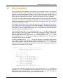
Introduction
The Stellaris Peripheral Driver Library is a set of drivers for accessing the peripherals found on the
Stellaris family of ARM® Cortex™-M3 based microcontrollers. While they are not drivers in the
pure operating system sense (i.e. they do not have a common interface and do not connect into
a global device driver infrastructure), they do provide a mechanism that makes it easy to use the
device’s peripherals.
The capabilities and organization of the drivers are governed by the following design goals:
They are written entirely in C except where absolutely not possible.
They demonstrate how to use the peripheral in its common mode of operation.
They are easy to understand.
They are reasonably efficient in terms of memory and processor usage.
They are as self-contained as possible.
Where possible, computations that can be performed at compile time are done there instead
of at run time.
Some consequences of these design goals are:
The drivers are not necessarily as efficient as they could be (from a code size and/or execution
speed point of view). While the most efficient piece of code for operating a peripheral would be
written in assembly and custom tailored to the specific requirements of the application, further
size optimizations of the drivers would make them more difficult to understand.
The drivers do not support the full capabilities of the hardware. Some of the peripherals
provide complex capabilities which can not be utilized by the drivers in this library, though
the existing code can be used as a reference upon which to add support for the additional
capabilities.
The APIs have a means of removing all error checking code. Since the error checking is
usually only useful during initial program development, it can be removed to improve code size
and speed.
For many applications, the drivers can be used as is. But in some cases, the drivers will have to be
enhanced or rewritten in order to meet the functionality, memory, or processing requirements of the
application. If so, the existing driver can be used as a reference on how to operate the peripheral.
October 11, 2007
7
Introduction
8
October 11, 2007
Stellaris Peripheral Driver Library User’s Guide
2
Analog Comparator
Introduction . . . . . . . . . . . . . . . . . . . . . . . . . . . . . . . . . . . . . . . . . . . . . . . . . . . . . . . . . . . . . . . . . . . . . . . . . . . . . . . . . . . . . . . . . . . . . . . 7
API Functions . . . . . . . . . . . . . . . . . . . . . . . . . . . . . . . . . . . . . . . . . . . . . . . . . . . . . . . . . . . . . . . . . . . . . . . . . . . . . . . . . . . . . . . . . . . . . 7
Programming Example . . . . . . . . . . . . . . . . . . . . . . . . . . . . . . . . . . . . . . . . . . . . . . . . . . . . . . . . . . . . . . . . . . . . . . . . . . . . . . . . . . . 13
2.1
Introduction
The comparator API provides a set of functions for dealing with the analog comparators. A comparator can compare a test voltage against individual external reference voltage, a shared single
external reference voltage, or a shared internal reference voltage. It can provide its output to a
device pin, acting as a replacement for an analog comparator on the board, or it can be used to
signal the application via interrupts or triggers to the ADC to cause it to start capturing a sample
sequence. The interrupt generation and ADC triggering logic is separate, so that an interrupt can
be generated on a rising edge and the ADC triggered on a falling edge (for example).
2.2
API Functions
Functions
void ComparatorConfigure (unsigned long ulBase, unsigned long ulComp, unsigned long ulConfig)
void ComparatorIntClear (unsigned long ulBase, unsigned long ulComp)
void ComparatorIntDisable (unsigned long ulBase, unsigned long ulComp)
void ComparatorIntEnable (unsigned long ulBase, unsigned long ulComp)
void ComparatorIntRegister (unsigned long ulBase, unsigned long ulComp, void (∗pfnHandler)(void))
tBoolean ComparatorIntStatus (unsigned long ulBase, unsigned long ulComp, tBoolean bMasked)
void ComparatorIntUnregister (unsigned long ulBase, unsigned long ulComp)
void ComparatorRefSet (unsigned long ulBase, unsigned long ulRef)
tBoolean ComparatorValueGet (unsigned long ulBase, unsigned long ulComp)
2.2.1
Detailed Description
The comparator API is fairly simple, like the comparators themselves. There are functions for
configuring a comparator and reading its output (ComparatorConfigure(), ComparatorRefSet()
and ComparatorValueGet()) and functions for dealing with an interrupt handler for the comparator (ComparatorIntRegister(), ComparatorIntUnregister(), ComparatorIntEnable(), ComparatorIntDisable(), ComparatorIntStatus(), and ComparatorIntClear()).
October 11, 2007
9
Analog Comparator
2.2.2
Function Documentation
2.2.2.1
ComparatorConfigure
Configures a comparator.
Prototype:
void
ComparatorConfigure(unsigned long ulBase,
unsigned long ulComp,
unsigned long ulConfig)
Parameters:
ulBase is the base address of the comparator module.
ulComp is the index of the comparator to configure.
ulConfig is the configuration of the comparator.
Description:
This function will configure a comparator. The ulConfig parameter is the result of a logical
OR operation between the COMP_TRIG_xxx, COMP_INT_xxx, COMP_ASRCP_xxx, and
COMP_OUTPUT_xxx values.
The COMP_TRIG_xxx term can take on the following values:
COMP_TRIG_NONE to have no trigger to the ADC.
COMP_TRIG_HIGH to trigger the ADC when the comparator output is high.
COMP_TRIG_LOW to trigger the ADC when the comparator output is low.
COMP_TRIG_FALL to trigger the ADC when the comparator output goes low.
COMP_TRIG_RISE to trigger the ADC when the comparator output goes high.
COMP_TRIG_BOTH to trigger the ADC when the comparator output goes low or high.
The COMP_INT_xxx term can take on the following values:
COMP_INT_HIGH to generate an interrupt when the comparator output is high.
COMP_INT_LOW to generate an interrupt when the comparator output is low.
COMP_INT_FALL to generate an interrupt when the comparator output goes low.
COMP_INT_RISE to generate an interrupt when the comparator output goes high.
COMP_INT_BOTH to generate an interrupt when the comparator output goes low or high.
The COMP_ASRCP_xxx term can take on the following values:
COMP_ASRCP_PIN to use the dedicated Comp+ pin as the reference voltage.
COMP_ASRCP_PIN0 to use the Comp0+ pin as the reference voltage (this the same as
COMP_ASRCP_PIN for the comparator 0).
COMP_ASRCP_REF to use the internally generated voltage as the reference voltage.
The COMP_OUTPUT_xxx term can take on the following values:
COMP_OUTPUT_NORMAL to enable a non-inverted output from the comparator to a
device pin.
COMP_OUTPUT_INVERT to enable an inverted output from the comparator to a device
pin.
10
October 11, 2007
Stellaris Peripheral Driver Library User’s Guide
COMP_OUTPUT_NONE is deprecated and behaves the same as COMP_OUTPUT_NORMAL.
Returns:
None.
2.2.2.2
ComparatorIntClear
Clears a comparator interrupt.
Prototype:
void
ComparatorIntClear(unsigned long ulBase,
unsigned long ulComp)
Parameters:
ulBase is the base address of the comparator module.
ulComp is the index of the comparator.
Description:
The comparator interrupt is cleared, so that it no longer asserts. This must be done in the
interrupt handler to keep it from being called again immediately upon exit. Note that for a level
triggered interrupt, the interrupt cannot be cleared until it stops asserting.
Returns:
None.
2.2.2.3
ComparatorIntDisable
Disables the comparator interrupt.
Prototype:
void
ComparatorIntDisable(unsigned long ulBase,
unsigned long ulComp)
Parameters:
ulBase is the base address of the comparator module.
ulComp is the index of the comparator.
Description:
This function disables generation of an interrupt from the specified comparator. Only comparators whose interrupts are enabled can be reflected to the processor.
Returns:
None.
October 11, 2007
11
Analog Comparator
2.2.2.4
ComparatorIntEnable
Enables the comparator interrupt.
Prototype:
void
ComparatorIntEnable(unsigned long ulBase,
unsigned long ulComp)
Parameters:
ulBase is the base address of the comparator module.
ulComp is the index of the comparator.
Description:
This function enables generation of an interrupt from the specified comparator. Only comparators whose interrupts are enabled can be reflected to the processor.
Returns:
None.
2.2.2.5
ComparatorIntRegister
Registers an interrupt handler for the comparator interrupt.
Prototype:
void
ComparatorIntRegister(unsigned long ulBase,
unsigned long ulComp,
void (*pfnHandler)(void))
Parameters:
ulBase is the base address of the comparator module.
ulComp is the index of the comparator.
pfnHandler is a pointer to the function to be called when the comparator interrupt occurs.
Description:
This sets the handler to be called when the comparator interrupt occurs. This will enable the
interrupt in the interrupt controller; it is the interrupt-handler’s responsibility to clear the interrupt
source via ComparatorIntClear().
See also:
IntRegister() for important information about registering interrupt handlers.
Returns:
None.
2.2.2.6
ComparatorIntStatus
Gets the current interrupt status.
12
October 11, 2007
Stellaris Peripheral Driver Library User’s Guide
Prototype:
tBoolean
ComparatorIntStatus(unsigned long ulBase,
unsigned long ulComp,
tBoolean bMasked)
Parameters:
ulBase is the base address of the comparator module.
ulComp is the index of the comparator.
bMasked is false if the raw interrupt status is required and true if the masked interrupt status
is required.
Description:
This returns the interrupt status for the comparator. Either the raw or the masked interrupt
status can be returned.
Returns:
true if the interrupt is asserted and false if it is not asserted.
2.2.2.7
ComparatorIntUnregister
Unregisters an interrupt handler for a comparator interrupt.
Prototype:
void
ComparatorIntUnregister(unsigned long ulBase,
unsigned long ulComp)
Parameters:
ulBase is the base address of the comparator module.
ulComp is the index of the comparator.
Description:
This function will clear the handler to be called when a comparator interrupt occurs. This will
also mask off the interrupt in the interrupt controller so that the interrupt handler no longer is
called.
See also:
IntRegister() for important information about registering interrupt handlers.
Returns:
None.
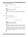
2.2.2.8
ComparatorRefSet
Sets the internal reference voltage.
Prototype:
void
ComparatorRefSet(unsigned long ulBase,
unsigned long ulRef)
October 11, 2007
13
Analog Comparator
Parameters:
ulBase is the base address of the comparator module.
ulRef is the desired reference voltage.
Description:
This function will set the internal reference voltage value. The voltage is specified as one of
the following values:
COMP_REF_OFF to turn off the reference voltage
COMP_REF_0V to set the reference voltage to 0 V
COMP_REF_0_1375V to set the reference voltage to 0.1375 V
COMP_REF_0_275V to set the reference voltage to 0.275 V
COMP_REF_0_4125V to set the reference voltage to 0.4125 V
COMP_REF_0_55V to set the reference voltage to 0.55 V
COMP_REF_0_6875V to set the reference voltage to 0.6875 V
COMP_REF_0_825V to set the reference voltage to 0.825 V
COMP_REF_0_928125V to set the reference voltage to 0.928125 V
COMP_REF_0_9625V to set the reference voltage to 0.9625 V
COMP_REF_1_03125V to set the reference voltage to 1.03125 V
COMP_REF_1_134375V to set the reference voltage to 1.134375 V
COMP_REF_1_1V to set the reference voltage to 1.1 V
COMP_REF_1_2375V to set the reference voltage to 1.2375 V
COMP_REF_1_340625V to set the reference voltage to 1.340625 V
COMP_REF_1_375V to set the reference voltage to 1.375 V
COMP_REF_1_44375V to set the reference voltage to 1.44375 V
COMP_REF_1_5125V to set the reference voltage to 1.5125 V
COMP_REF_1_546875V to set the reference voltage to 1.546875 V
COMP_REF_1_65V to set the reference voltage to 1.65 V
COMP_REF_1_753125V to set the reference voltage to 1.753125 V
COMP_REF_1_7875V to set the reference voltage to 1.7875 V
COMP_REF_1_85625V to set the reference voltage to 1.85625 V
COMP_REF_1_925V to set the reference voltage to 1.925 V
COMP_REF_1_959375V to set the reference voltage to 1.959375 V
COMP_REF_2_0625V to set the reference voltage to 2.0625 V
COMP_REF_2_165625V to set the reference voltage to 2.165625 V
COMP_REF_2_26875V to set the reference voltage to 2.26875 V
COMP_REF_2_371875V to set the reference voltage to 2.371875 V
Returns:
None.
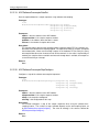
2.2.2.9
ComparatorValueGet
Gets the current comparator output value.
Prototype:
tBoolean
ComparatorValueGet(unsigned long ulBase,
unsigned long ulComp)
14
October 11, 2007
Stellaris Peripheral Driver Library User’s Guide
Parameters:
ulBase is the base address of the comparator module.
ulComp is the index of the comparator.
Description:
This function retrieves the current value of the comparator output.
Returns:
Returns true if the comparator output is high and false if the comparator output is low.
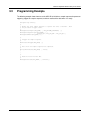
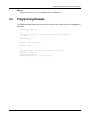
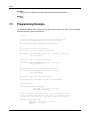
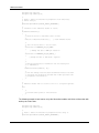
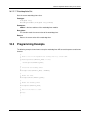
2.3
Programming Example
The following example shows how to use the comparator API to configure the comparator and read
its value.
//
// Configure the internal voltage reference.
//
ComparatorRefSet(COMP_BASE, COMP_REF_1_65V);
//
// Configure a comparator.
//
ComparatorConfigure(COMP_BASE, 0,
(COMP_TRIG_NONE | COMP_INT_BOTH |
COMP_ASRCP_REF | COMP_OUTPUT_NONE));
//
// Delay for some time...
//
//
// Read the comparator output value.
//
ComparatorValueGet(COMP_BASE, 0);
October 11, 2007
15
Analog Comparator
16
October 11, 2007
Stellaris Peripheral Driver Library User’s Guide
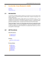
3
Analog to Digital Converter
Introduction . . . . . . . . . . . . . . . . . . . . . . . . . . . . . . . . . . . . . . . . . . . . . . . . . . . . . . . . . . . . . . . . . . . . . . . . . . . . . . . . . . . . . . . . . . . . . . 15
API Functions . . . . . . . . . . . . . . . . . . . . . . . . . . . . . . . . . . . . . . . . . . . . . . . . . . . . . . . . . . . . . . . . . . . . . . . . . . . . . . . . . . . . . . . . . . . . 15
Programming Example . . . . . . . . . . . . . . . . . . . . . . . . . . . . . . . . . . . . . . . . . . . . . . . . . . . . . . . . . . . . . . . . . . . . . . . . . . . . . . . . . . . 27
3.1
Introduction
The analog to digital converter (ADC) API provides a set of functions for dealing with the ADC.
Functions are provided to configure the sample sequencers, read the captured data, register a
sample sequence interrupt handler, and handle interrupt masking/clearing.
The ADC supports up to eight input channels plus an internal temperature sensor. Four sampling
sequences, each with configurable trigger events, can be captured. The first sequence will capture
up to eight samples, the second and third sequences will capture up to four samples, and the fourth
sequence will capture a single sample. Each sample can be the same channel, different channels,
or any combination in any order.
The sample sequences have configurable priorities that determine the order in which they are captured when multiple triggers occur simultaneously. The highest priority sequence that is currently
triggered will be sampled. Care must be taken with triggers that occur frequently (such as the
“always” trigger); if their priority is too high it is possible to starve the lower priority sequences.
Beginning with Rev C0 of the Stellaris microcontroller, hardware oversampling of the ADC data is
available for improved accuracy. An oversampling factor of 2x, 4x, 8x, 16x, 32x, and 64x is supported, but reduces the throughput of the ADC by a corresponding factor. Hardware oversampling
is applied uniformly across all sample sequences.
Software oversampling of the ADC data is also available (even when hardware oversampling is
available). An oversampling factor of 2x, 4x, and 8x is supported, but reduces the depth of the
sample sequences by a corresponding amount. For example, the first sample sequence will capture
eight samples; in 4x oversampling mode it can only capture two samples since the first four samples
are used over the first oversampled value and the second four samples are used for the second
oversampled value. The amount of software oversampling is configured on a per sample sequence
basis.
A more sophisticated software oversampling can be used to eliminate the reduction of the sample
sequence depth. By increasing the ADC trigger rate by 4x (for example) and averaging four triggers worth of data, 4x oversampling is achieved without any loss of sample sequence capability.
In this case, an increase in the number of ADC triggers (and presumably ADC interrupts) is the
consequence. Since this requires adjustments outside of the ADC driver itself, this is not directly
supported by the driver (though nothing in the driver prevents it). The software oversampling APIs
should not be used in this case.
3.2
API Functions
Functions
void ADCHardwareOversampleConfigure (unsigned long ulBase, unsigned long ulFactor)
October 11, 2007
17
Analog to Digital Converter
void ADCIntClear (unsigned long ulBase, unsigned long ulSequenceNum)
void ADCIntDisable (unsigned long ulBase, unsigned long ulSequenceNum)
void ADCIntEnable (unsigned long ulBase, unsigned long ulSequenceNum)
void ADCIntRegister (unsigned long ulBase, unsigned long ulSequenceNum, void (∗pfnHandler)(void))
unsigned long ADCIntStatus (unsigned long ulBase, unsigned long ulSequenceNum, tBoolean
bMasked)
void ADCIntUnregister (unsigned long ulBase, unsigned long ulSequenceNum)
void ADCProcessorTrigger (unsigned long ulBase, unsigned long ulSequenceNum)
void ADCSequenceConfigure (unsigned long ulBase, unsigned long ulSequenceNum, unsigned long ulTrigger, unsigned long ulPriority)
long ADCSequenceDataGet (unsigned long ulBase, unsigned long ulSequenceNum, unsigned long ∗pulBuffer)
void ADCSequenceDisable (unsigned long ulBase, unsigned long ulSequenceNum)
void ADCSequenceEnable (unsigned long ulBase, unsigned long ulSequenceNum)
long ADCSequenceOverflow (unsigned long ulBase, unsigned long ulSequenceNum)
void ADCSequenceOverflowClear (unsigned long ulBase, unsigned long ulSequenceNum)
void ADCSequenceStepConfigure (unsigned long ulBase, unsigned long ulSequenceNum,
unsigned long ulStep, unsigned long ulConfig)
long ADCSequenceUnderflow (unsigned long ulBase, unsigned long ulSequenceNum)
void ADCSequenceUnderflowClear (unsigned long ulBase, unsigned long ulSequenceNum)
void ADCSoftwareOversampleConfigure (unsigned long ulBase, unsigned long ulSequenceNum, unsigned long ulFactor)
void ADCSoftwareOversampleDataGet (unsigned long ulBase, unsigned long ulSequenceNum, unsigned long ∗pulBuffer, unsigned long ulCount)
void ADCSoftwareOversampleStepConfigure (unsigned long ulBase, unsigned long ulSequenceNum, unsigned long ulStep, unsigned long ulConfig)
3.2.1
Detailed Description
The analog to digital converter API is broken into three groups of functions: those that deal with
the sample sequences, those that deal with the processor trigger, and those that deal with interrupt
handling.
The sample sequences are configured with ADCSequenceConfigure() and ADCSequenceStepConfigure(). They are enabled and disabled with ADCSequenceEnable() and ADCSequenceDisable(). The captured data is obtained with ADCSequenceDataGet(). Sample sequence FIFO
overflow and underflow is managed with ADCSequenceOverflow(), ADCSequenceOverflowClear(),
ADCSequenceUnderflow(), and ADCSequenceUnderflowClear().
Hardware oversampling of the ADC is controlled with ADCHardwareOversampleConfigure().
Software oversampling of the ADC is controlled with ADCSoftwareOversampleConfigure(),
ADCSoftwareOversampleStepConfigure(), and ADCSoftwareOversampleDataGet().
The processor trigger is generated with ADCProcessorTrigger().
The interrupt handler for the ADC sample sequence interrupts are managed with ADCIntRegister()
and ADCIntUnregister(). The sample sequence interrupt sources are managed with ADCIntDisable(), ADCIntEnable(), ADCIntStatus(), and ADCIntClear().
18
October 11, 2007
Stellaris Peripheral Driver Library User’s Guide
3.2.2
Function Documentation
3.2.2.1
ADCHardwareOversampleConfigure
Configures the hardware oversampling factor of the ADC.
Prototype:
void
ADCHardwareOversampleConfigure(unsigned long ulBase,
unsigned long ulFactor)
Parameters:
ulBase is the base address of the ADC module.
ulFactor is the number of samples to be averaged.
Description:
This function configures the hardware oversampling for the ADC, which can be used to provide
better resolution on the sampled data. Oversampling is accomplished by averaging multiple
samples from the same analog input. Six different oversampling rates are supported; 2x, 4x,
8x, 16x, 32x, and 64x. Specifying an oversampling factor of zero will disable the hardware
oversampler.
Hardware oversampling applies uniformly to all sample sequencers. It does not reduce the
depth of the sample sequencers like the software oversampling APIs; each sample written into
the sample sequence FIFO is a fully oversampled analog input reading.
Enabling hardware averaging increases the precision of the ADC at the cost of throughput. For
example, enabling 4x oversampling reduces the throughput of a 250 KSps ADC to 62.5 KSps.
Note:
Hardware oversampling is available beginning with Rev C0 of the Stellaris microcontroller.
Returns:
None.
3.2.2.2
ADCIntClear
Clears sample sequence interrupt source.
Prototype:
void
ADCIntClear(unsigned long ulBase,
unsigned long ulSequenceNum)
Parameters:
ulBase is the base address of the ADC module.
ulSequenceNum is the sample sequence number.
Description:
The specified sample sequence interrupt is cleared, so that it no longer asserts. This must be
done in the interrupt handler to keep it from being called again immediately upon exit.
Returns:
None.
October 11, 2007
19
Analog to Digital Converter
3.2.2.3
ADCIntDisable
Disables a sample sequence interrupt.
Prototype:
void
ADCIntDisable(unsigned long ulBase,
unsigned long ulSequenceNum)
Parameters:
ulBase is the base address of the ADC module.
ulSequenceNum is the sample sequence number.
Description:
This function disables the requested sample sequence interrupt.
Returns:
None.
3.2.2.4
ADCIntEnable
Enables a sample sequence interrupt.
Prototype:
void
ADCIntEnable(unsigned long ulBase,
unsigned long ulSequenceNum)
Parameters:
ulBase is the base address of the ADC module.
ulSequenceNum is the sample sequence number.
Description:
This function enables the requested sample sequence interrupt. Any outstanding interrupts
are cleared before enabling the sample sequence interrupt.
Returns:
None.
3.2.2.5
ADCIntRegister
Registers an interrupt handler for an ADC interrupt.
Prototype:
void
ADCIntRegister(unsigned long ulBase,
unsigned long ulSequenceNum,
void (*pfnHandler)(void))
Parameters:
ulBase is the base address of the ADC module.
20
October 11, 2007
Stellaris Peripheral Driver Library User’s Guide
ulSequenceNum is the sample sequence number.
pfnHandler is a pointer to the function to be called when the ADC sample sequence interrupt
occurs.
Description:
This function sets the handler to be called when a sample sequence interrupt occurs. This will
enable the global interrupt in the interrupt controller; the sequence interrupt must be enabled
with ADCIntEnable(). It is the interrupt handler’s responsibility to clear the interrupt source via
ADCIntClear().
See also:
IntRegister() for important information about registering interrupt handlers.
Returns:
None.
3.2.2.6
ADCIntStatus
Gets the current interrupt status.
Prototype:
unsigned long
ADCIntStatus(unsigned long ulBase,
unsigned long ulSequenceNum,
tBoolean bMasked)
Parameters:
ulBase is the base address of the ADC module.
ulSequenceNum is the sample sequence number.
bMasked is false if the raw interrupt status is required and true if the masked interrupt status
is required.
Description:
This returns the interrupt status for the specified sample sequence. Either the raw interrupt
status or the status of interrupts that are allowed to reflect to the processor can be returned.
Returns:
The current raw or masked interrupt status.
3.2.2.7
ADCIntUnregister
Unregisters the interrupt handler for an ADC interrupt.
Prototype:
void
ADCIntUnregister(unsigned long ulBase,
unsigned long ulSequenceNum)
Parameters:
ulBase is the base address of the ADC module.
October 11, 2007
21
Analog to Digital Converter
ulSequenceNum is the sample sequence number.
Description:
This function unregisters the interrupt handler. This will disable the global interrupt in the
interrupt controller; the sequence interrupt must be disabled via ADCIntDisable().
See also:
IntRegister() for important information about registering interrupt handlers.
Returns:
None.
3.2.2.8
ADCProcessorTrigger
Causes a processor trigger for a sample sequence.
Prototype:
void
ADCProcessorTrigger(unsigned long ulBase,
unsigned long ulSequenceNum)
Parameters:
ulBase is the base address of the ADC module.
ulSequenceNum is the sample sequence number.
Description:
This function triggers a processor-initiated sample sequence if the sample sequence trigger is
configured to ADC_TRIGGER_PROCESSOR.
Returns:
None.
3.2.2.9
ADCSequenceConfigure
Configures the trigger source and priority of a sample sequence.
Prototype:
void
ADCSequenceConfigure(unsigned
unsigned
unsigned
unsigned
long
long
long
long
ulBase,
ulSequenceNum,
ulTrigger,
ulPriority)
Parameters:
ulBase is the base address of the ADC module.
ulSequenceNum is the sample sequence number.
ulTrigger is the trigger source that initiates the sample sequence; must be one of the ADC_TRIGGER_∗ values.
ulPriority is the relative priority of the sample sequence with respect to the other sample
sequences.
22
October 11, 2007
Stellaris Peripheral Driver Library User’s Guide
Description:
This function configures the initiation criteria for a sample sequence. Valid sample sequences
range from zero to three; sequence zero will capture up to eight samples, sequences one and
two will capture up to four samples, and sequence three will capture a single sample. The
trigger condition and priority (with respect to other sample sequence execution) is set.
The parameter ulTrigger can take on the following values:
ADC_TRIGGER_PROCESSOR - A trigger generated by the processor, via the
ADCProcessorTrigger() function.
ADC_TRIGGER_COMP0 - A trigger generated by the first analog comparator; configured
with ComparatorConfigure().
ADC_TRIGGER_COMP1 - A trigger generated by the second analog comparator; configured with ComparatorConfigure().
ADC_TRIGGER_COMP2 - A trigger generated by the third analog comparator; configured
with ComparatorConfigure().
ADC_TRIGGER_EXTERNAL - A trigger generated by an input from the Port B4 pin.
ADC_TRIGGER_TIMER - A trigger generated by a timer; configured with TimerControlTrigger().
ADC_TRIGGER_PWM0 - A trigger generated by the first PWM generator; configured with
PWMGenIntTrigEnable().
ADC_TRIGGER_PWM1 - A trigger generated by the second PWM generator; configured
with PWMGenIntTrigEnable().
ADC_TRIGGER_PWM2 - A trigger generated by the third PWM generator; configured with
PWMGenIntTrigEnable().
ADC_TRIGGER_ALWAYS - A trigger that is always asserted, causing the sample sequence to capture repeatedly (so long as there is not a higher priority source active).
Note that not all trigger sources are available on all Stellaris family members; consult the data
sheet for the device in question to determine the availability of triggers.
The parameter ulPriority is a value between 0 and 3, where 0 represents the highest priority
and 3 the lowest. Note that when programming the priority among a set of sample sequences,
each must have unique priority; it is up to the caller to guarantee the uniqueness of the priorities.
Returns:
None.
3.2.2.10 ADCSequenceDataGet
Gets the captured data for a sample sequence.
Prototype:
long
ADCSequenceDataGet(unsigned long ulBase,
unsigned long ulSequenceNum,
unsigned long *pulBuffer)
Parameters:
ulBase is the base address of the ADC module.
ulSequenceNum is the sample sequence number.
October 11, 2007
23
Analog to Digital Converter
pulBuffer is the address where the data is stored.
Description:
This function copies data from the specified sample sequence output FIFO to a memory resident buffer. The number of samples available in the hardware FIFO are copied into the buffer,
which is assumed to be large enough to hold that many samples. This will only return the
samples that are presently available, which may not be the entire sample sequence if it is in
the process of being executed.
Returns:
Returns the number of samples copied to the buffer.
3.2.2.11 ADCSequenceDisable
Disables a sample sequence.
Prototype:
void
ADCSequenceDisable(unsigned long ulBase,
unsigned long ulSequenceNum)
Parameters:
ulBase is the base address of the ADC module.
ulSequenceNum is the sample sequence number.
Description:
Prevents the specified sample sequence from being captured when its trigger is detected. A
sample sequence should be disabled before it is configured.
Returns:
None.
3.2.2.12 ADCSequenceEnable
Enables a sample sequence.
Prototype:
void
ADCSequenceEnable(unsigned long ulBase,
unsigned long ulSequenceNum)
Parameters:
ulBase is the base address of the ADC module.
ulSequenceNum is the sample sequence number.
Description:
Allows the specified sample sequence to be captured when its trigger is detected. A sample
sequence must be configured before it is enabled.
Returns:
None.
24
October 11, 2007
Stellaris Peripheral Driver Library User’s Guide
3.2.2.13 ADCSequenceOverflow
Determines if a sample sequence overflow occurred.
Prototype:
long
ADCSequenceOverflow(unsigned long ulBase,
unsigned long ulSequenceNum)
Parameters:
ulBase is the base address of the ADC module.
ulSequenceNum is the sample sequence number.
Description:
This determines if a sample sequence overflow has occurred. This will happen if the captured
samples are not read from the FIFO before the next trigger occurs.
Returns:
Returns zero if there was not an overflow, and non-zero if there was.
3.2.2.14 ADCSequenceOverflowClear
Clears the overflow condition on a sample sequence.
Prototype:
void
ADCSequenceOverflowClear(unsigned long ulBase,
unsigned long ulSequenceNum)
Parameters:
ulBase is the base address of the ADC module.
ulSequenceNum is the sample sequence number.
Description:
This will clear an overflow condition on one of the sample sequences. The overflow condition
must be cleared in order to detect a subsequent overflow condition (it otherwise causes no
harm).
Returns:
None.
3.2.2.15 ADCSequenceStepConfigure
Configure a step of the sample sequencer.
Prototype:
void
ADCSequenceStepConfigure(unsigned
unsigned
unsigned
unsigned
October 11, 2007
long
long
long
long
ulBase,
ulSequenceNum,
ulStep,
ulConfig)
25
Analog to Digital Converter
Parameters:
ulBase is the base address of the ADC module.
ulSequenceNum is the sample sequence number.
ulStep is the step to be configured.
ulConfig is the configuration of this step; must be a logical OR of ADC_CTL_TS, ADC_CTL_IE, ADC_CTL_END, ADC_CTL_D, and one of the input channel selects (ADC_CTL_CH0
through ADC_CTL_CH7).
Description:
This function will set the configuration of the ADC for one step of a sample sequence. The
ADC can be configured for single-ended or differential operation (the ADC_CTL_D bit selects
differential operation when set), the channel to be sampled can be chosen (the ADC_CTL_CH0 through ADC_CTL_CH7 values), and the internal temperature sensor can be selected
(the ADC_CTL_TS bit). Additionally, this step can be defined as the last in the sequence (the
ADC_CTL_END bit) and it can be configured to cause an interrupt when the step is complete
(the ADC_CTL_IE bit). The configuration is used by the ADC at the appropriate time when the
trigger for this sequence occurs.
The ulStep parameter determines the order in which the samples are captured by the ADC
when the trigger occurs. It can range from zero to seven for the first sample sequence, from
zero to three for the second and third sample sequence, and can only be zero for the fourth
sample sequence.
Differential mode only works with adjacent channel pairs (e.g. 0 and 1). The channel select must be the number of the channel pair to sample (e.g. ADC_CTL_CH0 for 0 and 1, or
ADC_CTL_CH1 for 2 and 3) or undefined results will be returned by the ADC. Additionally, if
differential mode is selected when the temperature sensor is being sampled, undefined results
will be returned by the ADC.
It is the responsibility of the caller to ensure that a valid configuration is specified; this function
does not check the validity of the specified configuration.
Returns:
None.
3.2.2.16 ADCSequenceUnderflow
Determines if a sample sequence underflow occurred.
Prototype:
long
ADCSequenceUnderflow(unsigned long ulBase,
unsigned long ulSequenceNum)
Parameters:
ulBase is the base address of the ADC module.
ulSequenceNum is the sample sequence number.
Description:
This determines if a sample sequence underflow has occurred. This will happen if too many
samples are read from the FIFO.
Returns:
Returns zero if there was not an underflow, and non-zero if there was.
26
October 11, 2007
Stellaris Peripheral Driver Library User’s Guide
3.2.2.17 ADCSequenceUnderflowClear
Clears the underflow condition on a sample sequence.
Prototype:
void
ADCSequenceUnderflowClear(unsigned long ulBase,
unsigned long ulSequenceNum)
Parameters:
ulBase is the base address of the ADC module.
ulSequenceNum is the sample sequence number.
Description:
This will clear an underflow condition on one of the sample sequences. The underflow condition
must be cleared in order to detect a subsequent underflow condition (it otherwise causes no
harm).
Returns:
None.
3.2.2.18 ADCSoftwareOversampleConfigure
Configures the software oversampling factor of the ADC.
Prototype:
void
ADCSoftwareOversampleConfigure(unsigned long ulBase,
unsigned long ulSequenceNum,
unsigned long ulFactor)
Parameters:
ulBase is the base address of the ADC module.
ulSequenceNum is the sample sequence number.
ulFactor is the number of samples to be averaged.
Description:
This function configures the software oversampling for the ADC, which can be used to provide
better resolution on the sampled data. Oversampling is accomplished by averaging multiple
samples from the same analog input. Three different oversampling rates are supported; 2x,
4x, and 8x.
Oversampling is only supported on the sample sequencers that are more than one sample in
depth (i.e. the fourth sample sequencer is not supported). Oversampling by 2x (for example)
divides the depth of the sample sequencer by two; so 2x oversampling on the first sample
sequencer can only provide four samples per trigger. This also means that 8x oversampling is
only available on the first sample sequencer.
Returns:
None.
October 11, 2007
27
Analog to Digital Converter
3.2.2.19 ADCSoftwareOversampleDataGet
Gets the captured data for a sample sequence using software oversampling.
Prototype:
void
ADCSoftwareOversampleDataGet(unsigned
unsigned
unsigned
unsigned
long
long
long
long
ulBase,
ulSequenceNum,
*pulBuffer,
ulCount)
Parameters:
ulBase is the base address of the ADC module.
ulSequenceNum is the sample sequence number.
pulBuffer is the address where the data is stored.
ulCount is the number of samples to be read.
Description:
This function copies data from the specified sample sequence output FIFO to a memory resident buffer with software oversampling applied. The requested number of samples are copied
into the data buffer; if there are not enough samples in the hardware FIFO to satisfy this many
oversampled data items then incorrect results will be returned. It is the caller’s responsibility to
read only the samples that are available and wait until enough data is available, for example as
a result of receiving an interrupt.
Returns:
None.
3.2.2.20 ADCSoftwareOversampleStepConfigure
Configures a step of the software oversampled sequencer.
Prototype:
void
ADCSoftwareOversampleStepConfigure(unsigned
unsigned
unsigned
unsigned
long
long
long
long
ulBase,
ulSequenceNum,
ulStep,
ulConfig)
Parameters:
ulBase is the base address of the ADC module.
ulSequenceNum is the sample sequence number.
ulStep is the step to be configured.
ulConfig is the configuration of this step.
Description:
This function configures a step of the sample sequencer when using the software oversampling feature. The number of steps available depends on the oversampling factor set
by ADCSoftwareOversampleConfigure(). The value of ulConfig is the same as defined for
ADCSequenceStepConfigure().
Returns:
None.
28
October 11, 2007
Stellaris Peripheral Driver Library User’s Guide
3.3
Programming Example
The following example shows how to use the ADC API to initialize a sample sequence for processor
triggering, trigger the sample sequence, and then read back the data when it is ready.
unsigned long ulValue;
//
// Enable the first sample sequence to capture the value of channel 0 when
// the processor trigger occurs.
//
ADCSequenceConfigure(ADC_BASE, 0, ADC_TRIGGER_PROCESSOR, 0);
ADCSequenceStepConfigure(ADC_BASE, 0, 0,
ADC_CTL_IE | ADC_CTL_END | ADC_CTL_CH0);
ADCSequenceEnable(ADC_BASE, 0);
//
// Trigger the sample sequence.
//
ADCProcessorTrigger(ADC_BASE, 0);
//
// Wait until the sample sequence has completed.
//
while(!ADCIntStatus(ADC_BASE, 0, false))
{
}
//
// Read the value from the ADC.
//
ADCSequenceDataGet(ADC_BASE, 0, &ulValue);
October 11, 2007
29
Analog to Digital Converter
30
October 11, 2007
Stellaris Peripheral Driver Library User’s Guide
4
Controller Area Network (CAN)
Introduction . . . . . . . . . . . . . . . . . . . . . . . . . . . . . . . . . . . . . . . . . . . . . . . . . . . . . . . . . . . . . . . . . . . . . . . . . . . . . . . . . . . . . . . . . . . . . . 29
API Functions . . . . . . . . . . . . . . . . . . . . . . . . . . . . . . . . . . . . . . . . . . . . . . . . . . . . . . . . . . . . . . . . . . . . . . . . . . . . . . . . . . . . . . . . . . . . 29
Programming Example . . . . . . . . . . . . . . . . . . . . . . . . . . . . . . . . . . . . . . . . . . . . . . . . . . . . . . . . . . . . . . . . . . . . . . . . . . . . . . . . . . . 49
4.1
Introduction
The Controller Area Network (CAN) APIs provide a set of functions for accessing the Stellaris CAN
modules. Functions are provided to configure the CAN controllers, configure message objects, and
manage CAN interrupts.
The Stellaris CAN module provides hardware processing of the CAN data link layer. It can be
configured with message filters and preloaded message data so that it can autonomously send
and receive messages on the bus, and notify the application accordingly. It automatically handles
generation and checking of CRCs, error processing, and retransmission of CAN messages.
The message objects are stored in the CAN controller and provide the main interface for the CAN
module on the CAN bus. There are 32 message objects that can each be programmed to handle
a separate message ID, or can be chained together for a sequence of frames with the same ID.
The message identifier filters provide masking that can be programmed to match any or all of the
message ID bits, and frame types.
4.2
API Functions
Data Structures
tCANBitClkParms
tCANMsgObject
Defines
MSG_OBJ_STATUS_MASK
Enumerations
tCANIntFlags
tCANIntStsReg
tCANObjFlags
tCANStatusCtrl
tCANStsReg
tMsgObjType
October 11, 2007
31
Controller Area Network (CAN)
Functions
void CANDisable (unsigned long ulBase)
void CANEnable (unsigned long ulBase)
tBoolean CANErrCntrGet (unsigned long ulBase, unsigned long ∗pulRxCount, unsigned long
∗pulTxCount)
void CANGetBitTiming (unsigned long ulBase, tCANBitClkParms ∗pClkParms)
long CANGetIntNumber (unsigned long ulBase)
void CANInit (unsigned long ulBase)
void CANIntClear (unsigned long ulBase, unsigned long ulIntClr)
void CANIntDisable (unsigned long ulBase, unsigned long ulIntFlags)
void CANIntEnable (unsigned long ulBase, unsigned long ulIntFlags)
void CANIntRegister (unsigned long ulBase, void (∗pfnHandler)(void))
unsigned long CANIntStatus (unsigned long ulBase, tCANIntStsReg eIntStsReg)
void CANIntUnregister (unsigned long ulBase)
void CANMessageClear (unsigned long ulBase, unsigned long ulObjID)
void CANMessageGet (unsigned long ulBase, unsigned long ulObjID, tCANMsgObject ∗pMsgObject, tBoolean bClrPendingInt)
void CANMessageSet (unsigned long ulBase, unsigned long ulObjID, tCANMsgObject ∗pMsgObject, tMsgObjType eMsgType)
void CANReadDataReg (unsigned char ∗pucData, unsigned long ∗pulRegister, int iSize)
unsigned long CANReadReg (unsigned long ulRegAddress)
tBoolean CANRetryGet (unsigned long ulBase)
void CANRetrySet (unsigned long ulBase, tBoolean bAutoRetry)
void CANSetBitTiming (unsigned long ulBase, tCANBitClkParms ∗pClkParms)
unsigned long CANStatusGet (unsigned long ulBase, tCANStsReg eStatusReg)
void CANWriteDataReg (unsigned char ∗pucData, unsigned long ∗pulRegister, int iSize)
void CANWriteReg (unsigned long ulRegAddress, unsigned long ulRegValue)
4.2.1
Detailed Description
The CAN APIs provide all of the functions needed by the application to implement an interrupt
driven CAN stack. These functions may be used to control any of the available CAN ports on a
Stellaris microcontroller, and can be used with one port without causing conflicts with the other
port.
The CAN module is disabled by default, so the the CANInit() function must be called before any
other CAN functions are called. This call initializes the message objects to a safe state prior to
enabling the controller on the CAN bus. Also, the bit timing values must be programmed prior to
enabling the CAN controller. The CANSetBitTiming() function should be called with the appropriate
bit timing values for the CAN bus. Once these two functions have been called, a CAN controller can
be enabled using the CANEnable(), and later disabled again using CANDisable() if needed. Calling
CANDisable() does not reinitialize a CAN controller, so it can be used to temporarily remove a CAN
controller from the bus.
The CAN controller is highly configurable and contains 32 message objects that can be programmed to automatically transmit and receive CAN messages under certain conditions. Message
objects allow the application to perform some actions automatically without interaction from the
microcontroller. Some examples of these actions are the following:
32
October 11, 2007
Stellaris Peripheral Driver Library User’s Guide
send a data frame immediately
send a data frame when a matching remote frame is seen on the CAN bus
receive a specific data frame
receive data frames that match a certain identifier pattern
To configure message objects to perform any of these actions, the application must first set up one
of the 32 message objects using CANMessageSet(). This function must be used to configure a
message object to send data, or to configure a message object to receive data. Each message
object can be configured to generate interrupts on transmission or reception of CAN messages.
When data is received from the CAN bus, the application can use the CANMessageGet() function to
read the received message. This function can also be used to read a message object that is already
configured in order to populate a message structure prior to making changes to the configuration
of a message object. Reading the message object using this function will also clear any pending
interrupt on the message object.
Once a message object has been configured using CANMessageSet(), it has allocated the message object and will continue to perform its programmed function unless it is released with a call to
CANMessageClear(). The application is not required to clear out a message object before setting
it with a new configuration, because each time CANMessageSet() is called, it will overwrite any
previously programmed configuration.
The 32 message objects are identical except for priority. The lowest numbered message objects
have the highest priority. Priority affects operation in two ways. First if multiple actions are ready
at the same time, the one with the highest priority message object will occur first. And second,
when multiple message objects have interrupts pending, the highest priority will be presented first
when reading the interrupt status. It is up to the application to manage the 32 message objects as
a resource, and determine the best method for allocating and releasing them.
The CAN controller can generate interrupts on several conditions:
when any message object transmits a message
when any message object receives a message
on warning conditions such as an error counter reaching a limit or occurrence of various bus
errors
on controller error conditions such as entering the bus-off state
An interrupt handler must be installed in order to process CAN interrupts. If dynamic interrupt
configuration is desired, the CANIntRegister() can be used to register the interrupt handler. This
will place the vector in a RAM based vector table. If instead, the application uses a pre-loaded
vector table in flash, then the CAN controller handler should be entered in the appropriate slot
in the vector table. In this case CANIntRegister() is not needed, but the interrupt will need to be
enabled on the host processor master interrupt controller using the IntEnable() function. The CAN
module interrupts are enabled using the CANIntEnable() function. They can be disabled by using
the CANIntDisable() function.
Once CAN interrupts are enabled, the handler will be invoked whenever a CAN interrupt is triggered.
The handler can determines which condition caused the interrupt by using the CANIntStatus()
function. Multiple conditions can be pending when an interrupt occurs, so the handler must be
designed to process all pending interrupt conditions before exiting. Each interrupt condition must
be cleared before exiting the handler. There are two ways to do this. The CANIntClear() function
will clear a specific interrupt condition without further action required by the handler. However,
the handler can also clear the condition by performing certain actions. If the interrupt is a status
interrupt, the interrupt can be cleared by reading the status register with CANStatusGet(). If the
October 11, 2007
33
Controller Area Network (CAN)
interrupt is caused by one of the message objects, then it can be cleared by reading the message
object using CANMessageGet().
There are several status registers that can be used to help the application manage the controller.
The status registers are read using the CANStatusGet() function. There is a controller status register that provides general status information such as error or warning conditions. There are also
several status registers that provide information about all of the message objects at once using a
32-bit bit map of the status, with one bit representing each message object. These status registers
can be used to determine:
which message objects have unprocessed received data
which message objects have pending transmission requests
which message objects are allocated for use
The CAN controller also supports several test modes. With the test modes you can do the following:
force the TX pin into a known state
cause the sample clock to appear on the TX pin, which could be used to help diagnose bus
timing
put the controller into an internal loopback mode
put the controller into a "silent" mode where it will operate and receive messages, but will not
transmit anything onto the CAN bus
put the controller into a basic read/write mode where the message objects are not used and
a simple read/write interface is used to immediately send and receive messages without any
automatic processing features
The application can put the CAN controller into a test mode using the CANTestSet() function. If
the controller is placed in this mode, then the functions CANTestRead() and CANTestWrite() should
be used to receive and send messages on the CAN bus. These functions will directly send a
message, or receive a message if any are pending. In this test mode there is no automatic filtering
or processing.
4.2.2
Data Structure Documentation
4.2.2.1
tCANBitClkParms
Definition:
typedef struct
{
unsigned int
unsigned int
unsigned int
unsigned int
}
tCANBitClkParms
uSyncPropPhase1Seg;
uPhase2Seg;
uSJW;
uQuantumPrescaler;
Members:
uSyncPropPhase1Seg This value holds the sum of the Synchronization, Propagation, and
Phase Buffer 1 segments, measured in time quanta. The valid values for this setting range
from 2 to 16.
34
October 11, 2007
Stellaris Peripheral Driver Library User’s Guide
uPhase2Seg This value holds the Phase Buffer 2 segment in time quanta. The valid values
for this setting range from 1 to 8.
uSJW This value holds the Resynchronization Jump Width in time quanta. The valid values
for this setting range from 1 to 4.
uQuantumPrescaler This value holds the CAN_CLK divider used to determine time quanta.
The valid values for this setting range from 1 to 1023.
Description:
This structure is used for encapsulating the values associated with setting up the bit timing for a
CAN controller. The structure is used when calling the CANGetBitTiming and CANSetBitTiming
functions.
4.2.2.2
tCANMsgObject
Definition:
typedef struct
{
unsigned long
unsigned long
unsigned long
unsigned long
unsigned char
}
tCANMsgObject
ulMsgID;
ulMsgIDMask;
ulFlags;
ulMsgLen;
*pucMsgData;
Members:
ulMsgID The CAN message identifier used for 11 or 29 bit identifiers.
ulMsgIDMask The message identifier mask used when identifier filtering is enabled.
ulFlags This value holds various status flags and settings specified by tCANObjFlags.
ulMsgLen This value is the number of bytes of data in the message object.
pucMsgData This is a pointer to the message object’s data.
Description:
This structure used for encapsulating all the items associated with a CAN message object in
the CAN controller.
4.2.3
Define Documentation
4.2.3.1
MSG_OBJ_STATUS_MASK
Definition:
#define MSG_OBJ_STATUS_MASK
Description:
This define is used with the tCANObjFlags enumerated values to allow checking only status
flags and not configuration flags.
October 11, 2007
35
Controller Area Network (CAN)
4.2.4
Enumeration Documentation
4.2.4.1
tCANIntFlags
Description:
These definitions are used to specify interrupt sources to CANIntEnable() and CANIntDisable().
Enumerators:
CAN_INT_ERROR This flag is used to allow a CAN controller to generate error interrupts.
CAN_INT_STATUS This flag is used to allow a CAN controller to generate status interrupts.
CAN_INT_MASTER This flag is used to allow a CAN controller to generate any CAN interrupts. If this is not set then no interrupts will be generated by the CAN controller.
4.2.4.2
tCANIntStsReg
Description:
This data type is used to identify the interrupt status register. This is used when calling the a
CANIntStatus() function.
Enumerators:
CAN_INT_STS_CAUSE Read the CAN interrupt status information.
CAN_INT_STS_OBJECT Read a message object’s interrupt status.
4.2.4.3
tCANObjFlags
Description:
These are the flags used by the tCANMsgObject variable when calling the the CANMessageSet() and CANMessageGet() APIs.
Enumerators:
MSG_OBJ_TX_INT_ENABLE This indicates that transmit interrupts should be enabled, or
are enabled.
MSG_OBJ_RX_INT_ENABLE This indicates that receive interrupts should be enabled or
are enabled.
MSG_OBJ_EXTENDED_ID This indicates that a message object will use or is using an extended identifier.
MSG_OBJ_USE_ID_FILTER This indicates that a message object will use or is using filtering based on the object’s message Identifier.
MSG_OBJ_NEW_DATA This indicates that new data was available in the message object.
MSG_OBJ_DATA_LOST This indicates that data was lost since this message object was
last read.
MSG_OBJ_USE_DIR_FILTER This indicates that a message object will use or is using filtering based on the direction of the transfer. If the direction filtering is used then ID filtering
must also be enabled.
MSG_OBJ_USE_EXT_FILTER This indicates that a message object will use or is using message identifier filtering based of the the extended identifier. If the extended identifier filtering
is used then ID filtering must also be enabled.
MSG_OBJ_REMOTE_FRAME This indicates that a message object is a remote frame.
MSG_OBJ_NO_FLAGS This indicates that a message object has no flags set.
36
October 11, 2007
Stellaris Peripheral Driver Library User’s Guide
4.2.4.4
tCANStatusCtrl
Description:
The following enumeration contains all error or status indicators that can be returned when
calling the CANStatusGet() API.
Enumerators:
CAN_STATUS_BUS_OFF CAN controller has entered a Bus Off state.
CAN_STATUS_EWARN CAN controller error level has reached warning level.
CAN_STATUS_EPASS CAN controller error level has reached error passive level.
CAN_STATUS_RXOK A message was received successfully since the last read of this status.
CAN_STATUS_TXOK A message was transmitted successfully since the last read of this
status.
CAN_STATUS_LEC_MSK This is the mask for the last error code field.
CAN_STATUS_LEC_NONE There was no error.
CAN_STATUS_LEC_STUFF A bit stuffing error has occurred.
CAN_STATUS_LEC_FORM A formatting error has occurred.
CAN_STATUS_LEC_ACK An acknowledge error has occurred.
CAN_STATUS_LEC_BIT1 The bus remained a bit level of 1 for longer than is allowed.
CAN_STATUS_LEC_BIT0 The bus remained a bit level of 0 for longer than is allowed.
CAN_STATUS_LEC_CRC A CRC error has occurred.
CAN_STATUS_LEC_MASK This is the mask for the CAN Last Error Code (LEC).
4.2.4.5
tCANStsReg
Description:
This data type is used to identify which of the several status registers to read when calling the
CANStatusGet() function.
Enumerators:
CAN_STS_CONTROL Read the full CAN controller status.
CAN_STS_TXREQUEST Read the full 32 bit mask of message objects with a transmit request set.
CAN_STS_NEWDAT Read the full 32 bit mask of message objects with a new data available.
CAN_STS_MSGVAL Read the full 32 bit mask of message objects that are enabled.
4.2.4.6
tMsgObjType
Description:
This definition is used to determine the type of message object that will be set up via a call to
the CANMessageSet() API.
Enumerators:
MSG_OBJ_TYPE_TX Transmit message object.
MSG_OBJ_TYPE_TX_REMOTE Transmit remote request message object.
October 11, 2007
37
Controller Area Network (CAN)
MSG_OBJ_TYPE_RX Receive message object.
MSG_OBJ_TYPE_RX_REMOTE Receive remote request message object.
MSG_OBJ_TYPE_RXTX_REMOTE Remote frame receive remote, with auto-transmit message object.
4.2.5
Function Documentation
4.2.5.1
CANDisable
Disables the CAN controller.
Prototype:
void
CANDisable(unsigned long ulBase)
Parameters:
ulBase is the base address of the CAN controller to disable.
Description:
Disables the CAN controller for message processing. When disabled, the controller will no
longer automatically process data on the CAN bus. The controller can be restarted by calling
CANEnable(). The state of the CAN controller and the message objects in the controller are
left as they were before this call was made.
Returns:
None.
4.2.5.2
CANEnable
Enables the CAN controller.
Prototype:
void
CANEnable(unsigned long ulBase)
Parameters:
ulBase is the base address of the CAN controller to enable.
Description:
Enables the CAN controller for message processing. Once enabled, the controller will automatically transmit any pending frames, and process any received frames. The controller
can be stopped by calling CANDisable(). Prior to calling CANEnable(), CANInit() should have
been called to initialize the controller and the CAN bus clock should be configured by calling
CANSetBitTiming().
Returns:
None.
38
October 11, 2007
Stellaris Peripheral Driver Library User’s Guide
4.2.5.3
CANErrCntrGet
Reads the CAN controller error counter register.
Prototype:
tBoolean
CANErrCntrGet(unsigned long ulBase,
unsigned long *pulRxCount,
unsigned long *pulTxCount)
Parameters:
ulBase is the base address of the CAN controller.
pulRxCount is a pointer to storage for the receive error counter.
pulTxCount is a pointer to storage for the transmit error counter.
Description:
Reads the error counter register and returns the transmit and receive error counts to the caller
along with a flag indicating if the controller receive counter has reached the error passive
limit. The values of the receive and transmit error counters are returned through the pointers
provided as parameters.
After this call, ∗pulRxCount will hold the current receive error count and ∗pulTxCount will hold
the current transmit error count.
Returns:
true if the receive error count has reached the error passive limit.
false if the error count is below the error passive limit.
4.2.5.4
CANGetBitTiming
Reads the current settings for the CAN controller bit timing.
Prototype:
void
CANGetBitTiming(unsigned long ulBase,
tCANBitClkParms *pClkParms)
Parameters:
ulBase is the base address of the CAN controller.
pClkParms is a pointer to a structure to hold the timing parameters.
Description:
This function reads the current configuration of the CAN controller bit clock timing, and stores
the resulting information in the structure supplied by the caller. Refer to CANSetBitTiming() for
the meaning of the values that are returned in the structure pointed to by pClkParms.
Returns:
None.
October 11, 2007
39
Controller Area Network (CAN)
4.2.5.5
CANGetIntNumber
Returns the CAN controller interrupt number.
Prototype:
long
CANGetIntNumber(unsigned long ulBase)
Parameters:
ulBase is the base address of the selected CAN controller
Description:
Given a CAN controller base address, returns the corresponding interrupt number.
Returns:
Returns a CAN interrupt number, or -1 if ulPort is invalid.
4.2.5.6
CANInit
Initializes the CAN controller after reset.
Prototype:
void
CANInit(unsigned long ulBase)
Parameters:
ulBase is the base address of the CAN controller.
Description:
After reset, the CAN controller is left in the disabled state. However, the memory used for
message objects contains undefined values and must be cleared prior to enabling the CAN
controller the first time. This prevents unwanted transmission or reception of data before the
message objects are configured. This function must be called before enabling the controller
the first time.
Returns:
None.
4.2.5.7
CANIntClear
This call is used to clears a CAN interrupt source.
Prototype:
void
CANIntClear(unsigned long ulBase,
unsigned long ulIntClr)
Parameters:
ulBase is the base address of the CAN controller.
ulIntClr is a value indicating which interrupt source to clear
40
October 11, 2007
Stellaris Peripheral Driver Library User’s Guide
Description:
This function can be used to clear a specific interrupt source. The parameter ulIntClr should
be one of the following values:
CAN_INT_INTID_STATUS - Clears a status interrupt.
1-32 - Clear the specified message object interrupt
It is not necessary to use this function to clear an interrupt. This should only be used if the
application wants to clear an interrupt source without taking the normal interrupt action.
Normally, the status interrupt is cleared by reading the controller status, by calling CANStatusGet(). A specific message object interrupt is normally cleared by reading the message object
(see CANMessageGet()).
Returns:
None.
4.2.5.8
CANIntDisable
Disables individual CAN controller interrupt sources.
Prototype:
void
CANIntDisable(unsigned long ulBase,
unsigned long ulIntFlags)
Parameters:
ulBase is the base address of the CAN controller.
ulIntFlags is the bit mask of the interrupt sources to be disabled.
Description:
Disables the specified CAN controller interrupt sources. Only enabled interrupt sources can
cause a processor interrupt.
The parameter ulIntFlags has the same definition as in the function CANIntEnable().
Returns:
None.
4.2.5.9
CANIntEnable
Enables individual CAN controller interrupt sources.
Prototype:
void
CANIntEnable(unsigned long ulBase,
unsigned long ulIntFlags)
Parameters:
ulBase is the base address of the CAN controller.
ulIntFlags is the bit mask of the interrupt sources to be enabled.
October 11, 2007
41
Controller Area Network (CAN)
Description:
Enables specific interrupt sources of the CAN controller. Only enabled sources will cause a
processor interrupt.
The parameter ulIntFlags is the logical OR of any of the following:
CAN_INT_ERROR - controller error condition has occurred
CAN_INT_STATUS - a message transfer completed, or bus error detected
CAN_INT_MASTER - allow CAN controller to generate interrupts
In order to generate any interrupts, CAN_INT_MASTER must be enabled. Further, for any
particular transaction from a message object to generate an interrupt, that message object
must have interrupts enabled (see CANMessageSet()). CAN_INT_ERROR will generate an
interrupt if the controller enters the "bus off" condition, or if the error counters reach a limit.
CAN_INT_STATUS will generate an interrupt under quite a few status conditions and may
provide more interrupts than the application needs to handle. When an interrupt occurs, use
CANIntStatus() to determine the cause.
Returns:
None.
4.2.5.10 CANIntRegister
Registers an interrupt handler for the CAN controller.
Prototype:
void
CANIntRegister(unsigned long ulBase,
void (*pfnHandler)(void))
Parameters:
ulBase is the base address of the CAN controller.
pfnHandler is a pointer to the function to be called when the enabled CAN interrupts occur.
Description:
This function registers the interrupt handler in the interrupt vector table, and enables CAN
interrupts on the interrupt controller; specific CAN interrupt sources must be enabled using
CANIntEnable(). The interrupt handler being registered must clear the source of the interrupt
using CANIntClear();
If the application is using a static interrupt vector table stored in flash, then it is not necessary
to register the interrupt handler this way. Instead, IntEnable() should be used to enable CAN
interrupts on the interrupt controller.
See also:
IntRegister() for important information about registering interrupt handlers.
Returns:
None.
42
October 11, 2007
Stellaris Peripheral Driver Library User’s Guide
4.2.5.11 CANIntStatus
Returns the current CAN controller interrupt status.
Prototype:
unsigned long
CANIntStatus(unsigned long ulBase,
tCANIntStsReg eIntStsReg)
Parameters:
ulBase is the base address of the CAN controller.
eIntStsReg indicates which interrupt status register to read
Description:
Returns the value of one of two interrupt status registers. The interrupt status register read is
determined by the parameter eIntStsReg, which can have one of the following values:
CAN_INT_STS_CAUSE - indicates the cause of the interrupt
CAN_INT_STS_OBJECT - indicates pending interrupts of all message objects
CAN_INT_STS_CAUSE returns the value of the controller interrupt register and indicates the
cause of the interrupt. It will be a value of CAN_INT_INTID_STATUS if the cause is a status
interrupt. In this case, the status register should be read with the CANStatusGet() function.
Calling this function to read the status will also clear the status interrupt. If the value of the
interrupt register is in the range 1-32, then this indicates the number of the highest priority
message object that has an interrupt pending. The message object interrupt can be cleared by
using the CANIntClear() function, or by reading the message using CANMessageGet() in the
case of a received message. The interrupt handler can read the interrupt status again to make
sure all pending interrupts are cleared before returning from the interrupt.
CAN_INT_STS_OBJECT returns a bit mask indicating which message objects have pending
interrupts. This can be used to discover all of the pending interrupts at once, as opposed to
repeatedly reading the interrupt register by using CAN_INT_STS_CAUSE.
Returns:
The value of one of the interrupt status registers.
4.2.5.12 CANIntUnregister
Unregisters an interrupt handler for the CAN controller.
Prototype:
void
CANIntUnregister(unsigned long ulBase)
Parameters:
ulBase is the base address of the controller.
Description:
This function unregisters the previously registered interrupt handler and disables the interrupt
on the interrupt controller.
See also:
IntRegister() for important information about registering interrupt handlers.
October 11, 2007
43
Controller Area Network (CAN)
Returns:
None.
4.2.5.13 CANMessageClear
Clears a message object so that it is no longer used
Prototype:
void
CANMessageClear(unsigned long ulBase,
unsigned long ulObjID)
Parameters:
ulBase is the base address of the CAN controller.
ulObjID is the message object number to disable (1-32)
Description:
This function frees the specified message object from use. Once a message object has been
"cleared" it will no longer automatically send or receive messages, or generate interrupts.
Returns:
None.
4.2.5.14 CANMessageGet
Reads a CAN message from one of the message object buffers
Prototype:
void
CANMessageGet(unsigned long ulBase,
unsigned long ulObjID,
tCANMsgObject *pMsgObject,
tBoolean bClrPendingInt)
Parameters:
ulBase is the base address of the CAN controller.
ulObjID is the object number to read (1-32)
pMsgObject points to a structure containing message object fields
bClrPendingInt indicates whether an associated interrupt should be cleared
Description:
This function is used to read the contents of one of the 32 message objects in the CAN controller, and return it to the caller. The data returned is stored in the fields of the caller supplied
structure pointed to by pMsgObject. The data consists of all of the parts of a CAN message,
plus some control and status information.
Normally this is used to read a message object that has received and stored a CAN message
with a certain identifier. However this could also be used to read the contents of a message
object in order to load the fields of the structure in case only part of the structure needs to be
changed from a previous setting.
44
October 11, 2007
Stellaris Peripheral Driver Library User’s Guide
When using CANMessageGet, all of the same fields of the structure are populated in the same
way as when the CANMessageSet() function is used, with the following exceptions:
pMsgObject->ulFlags:
MSG_OBJ_NEW_DATA indicates if this is new data since the last time it was read
MSG_OBJ_DATA_LOST indicates that at least one message was received on this message object, and not read by the host before being overwritten.
Returns:
None.
4.2.5.15 CANMessageSet
Configures a message object in the CAN controller.
Prototype:
void
CANMessageSet(unsigned long ulBase,
unsigned long ulObjID,
tCANMsgObject *pMsgObject,
tMsgObjType eMsgType)
Parameters:
ulBase is the base address of the CAN controller.
ulObjID is the object number to configure (1-32)
pMsgObject is a pointer to a structure containing message object settings.
eMsgType Indicates what type of message this object is.
Description:
This function is used to configure any one of the 32 message objects in the CAN controller.
A message object can be configured as any type of CAN message object as well as several
options for automatic transmission and reception. This call also allows the message object to
be configured to generate interrupts on completion of message receipt or transmission. The
message object can also be configured with a filter/mask so that actions are only taken when
a message that meets certain parameters is seen on the CAN bus.
The eMsgType parameter must be one of the following values:
MSG_OBJ_TYPE_TX - CAN transmit message object.
MSG_OBJ_TYPE_TX_REMOTE - CAN transmit remote request message object.
MSG_OBJ_TYPE_RX - CAN receive message object.
MSG_OBJ_TYPE_RX_REMOTE - CAN receive remote request message object.
MSG_OBJ_TYPE_RXTX_REMOTE - CAN remote frame receive remote, then transmit
message object.
The message object pointed to by pMsgObject must be populated by the caller, as follows:
ulMsgID - contains the message ID, either 11 or 29 bits.
ulMsgIDMask - mask of bits from ulMsgID that must match if identifier filtering is enabled.
ulFlags
• Set MSG_OBJ_TX_INT_ENABLE flag to enable interrupt on transmission.
October 11, 2007
45
Controller Area Network (CAN)
• Set MSG_OBJ_RX_INT_ENABLE flag to enable interrupt on receipt.
• Set MSG_OBJ_USE_ID_FILTER flag to enable filtering based on the identifier mask
specified by ulMsgIDMask .
ulMsgLen - the number of bytes in the message data. This should be non-zero even for a
remote frame - it should match the expected bytes of the data responding data frame.
pucMsgData - points to a buffer containing up to 8 bytes of data for a data frame
To send a data frame or remote frame directly, take the following steps:
set tMsgObjType to MSG_OBJ_TYPE_TX.
set ulMsgID to the message ID.
set ulFlags Set MSG_OBJ_TX_INT_ENABLE to to get an interrupt when the message is
sent. To disable filtering based on message identifiers, do not set MSG_OBJ_USE_ID_FILTER.
set ulMsgLen to the number of bytes in the data frame.
set pucMsgData to point to an array containing the bytes in the message (if a data frame,
n/a if remote frame, though it is a good idea to set this to point to a valid buffer).
call this function with ulObjID set to one of the 32 object buffers.
To receive a specific data frame, take the following steps:
set tMsgObjType to MSG_OBJ_TYPE_RX.
set ulMsgID to the full message ID, or a partial mask to use partial ID matching.
set ulMsgIDMask bits that should be used for masking during comparison.
ulFlags
• Set MSG_OBJ_TX_INT_ENABLE flag to be interrupted when the data frame is received.
• Set MSG_OBJ_USE_ID_FILTER flag to enable identifier based filtering.
set ulMsgLen to the number of bytes in the expected data frame
the buffer pointed to by pucMsgData is not used for this call
call this function with ulObjID set to one of the 32 object buffers
If you specify a message object buffer that already contains a message definition, it will be
overwritten.
Returns:
None.
4.2.5.16 CANReadDataReg
This function copies data from a buffer to the CAN Data registers.
Prototype:
void
CANReadDataReg(unsigned char *pucData,
unsigned long *pulRegister,
int iSize)
Parameters:
pucData is a pointer to location to store the data read from the CAN controller’s data registers.
46
October 11, 2007
Stellaris Peripheral Driver Library User’s Guide
pulRegister is an unsigned long pointer to the first register of the CAN controller’s data registers. For example in order to use the IF1 register set on CAN controller 1 the value would
be: (CAN0_BASE + CAN_O_IF1DA1).
iSize is the number of bytes to copy from the CAN controller.
Description:
This function takes the steps necessary to copy data to a contiguous buffer in memory from the
non-contiguous data registers used by the CAN controller. This function is rarely used outside
of the CANMessageGet() function.
Returns:
None.
4.2.5.17 CANReadReg
Reads a CAN controller register.
Prototype:
unsigned long
CANReadReg(unsigned long ulRegAddress)
Parameters:
ulRegAddress is the full address of the CAN register to be read.
Description:
This function takes care of the synchronization necessary to read from a CAN controller register.
Note:
This function takes care of delay required to access CAN registers. This delay is required when
accessing CAN registers directly.
Returns:
The current value of the register that was requested by ulRegAddress.
4.2.5.18 CANRetryGet
Returns the current setting for auto-retransmission.
Prototype:
tBoolean
CANRetryGet(unsigned long ulBase)
Parameters:
ulBase is the base address of the CAN controller.
Description:
Reads the current setting of the auto-retransmission setting in the CAN controller and returns
it to the caller.
Returns:
true if automatic retransmission is enabled, false otherwise.
October 11, 2007
47
Controller Area Network (CAN)
4.2.5.19 CANRetrySet
Sets the CAN controller auto-retransmission behavior.
Prototype:
void
CANRetrySet(unsigned long ulBase,
tBoolean bAutoRetry)
Parameters:
ulBase is the base address of the CAN controller.
bAutoRetry enables auto-retransmission
Description:
Enables or disables automatic retransmission of messages with detected errors. If bAutoRetry
is true, then auto-retransmission is enabled, otherwise it is disabled.
Returns:
None.
4.2.5.20 CANSetBitTiming
Configures the CAN controller bit timing.
Prototype:
void
CANSetBitTiming(unsigned long ulBase,
tCANBitClkParms *pClkParms)
Parameters:
ulBase is the base address of the CAN controller.
pClkParms points to the structure with the clock parameters
Description:
Configures the various timing parameters for the CAN bus bit timing: Propagation segment,
Phase Buffer 1 segment, Phase Buffer 2 segment, and the Synchronization Jump Width. The
values for Propagation and Phase Buffer 1 segments are derived from the combination parameter pClkParms->uSyncPropPhase1Seg. Phase Buffer 2 is determined from the parameter
pClkParms->uPhase2Seg. These two parameters, along with pClkParms->uSJW are based
in units of bit time quanta. The actual quantum time is determined by the pClkParms->uQuantumPrescaler value, which specifies what the divisor for the CAN module clock.
The total bit time, in quanta, will be the sum of the two Seg parameters, as follows:
bit_time_q = uSyncPropPhase1Seg + uPhase2Seg + 1
Note that the Sync_Seg is always one quantum in duration, and will be added to derive the
correct duration of Prop_Seg and Phase1_Seg.
The equation to determine the actual bit rate is as follows:
CAN Clock / ((uSyncPropPhase1Seg + uPhase2Seg + 1)∗(uQuantumPrescaler ))
This means that with uSyncPropPhase1Seg = 4, uPhase2Seg = 1, uQuantumPrescaler = 2
and a 8MHz CAN clock, that the bit rate will be (8MHz)/((5 + 2 + 1)∗2) or 500 KBit/sec.
48
October 11, 2007
Stellaris Peripheral Driver Library User’s Guide
Returns:
None.
4.2.5.21 CANStatusGet
Reads one of the controller status registers.
Prototype:
unsigned long
CANStatusGet(unsigned long ulBase,
tCANStsReg eStatusReg)
Parameters:
ulBase is the base address of the CAN controller.
eStatusReg is the status register to read
Description:
Reads a status register of the CAN controller and returns it to the caller. The different status
registers are:
CAN_STS_CONTROL - the main controller status
CAN_STS_TXREQUEST - bit mask of objects pending transmission
CAN_STS_NEWDAT - bit mask of objects with new data
CAN_STS_MSGVAL - bit mask of objects with valid configuration
When reading the main controller status register, a pending status interrupt will be cleared.
This should be used in the interrupt handler for the CAN controller if the cause is a status
interrupt. The fields of controller status register are as follows:
CAN_STS_BOFF - controller is in bus-off condition
CAN_STS_EWARN - an error counter has reached a limit of at least 96
CAN_STS_EPASS - CAN controller is in the error passive state
CAN_STS_RXOK - a message was received successfully (independent of any message
filtering.
CAN_STS_TXOK - a message was successfully transmitted
CAN_STS_LEC_MSK - mask of last error code bits (3 bits)
CAN_STS_LEC_NONE - no error
CAN_STS_LEC_STUFF - stuffing error detected
CAN_STS_LEC_FORM - a format error in the fixed format part of a message
CAN_STS_LEC_ACK - a transmitted message was not acknowledged
CAN_STS_LEC_BIT1 - dominant level detected when trying to send recessive
CAN_STS_LEC_BIT0 - recessive level detected when trying to send dominant
CAN_STS_LEC_CRC - CRC error in received message
The remaining status registers are 32-bit bit maps to the message objects. They can be used to
quickly obtain information about the status of all the message object without needing to query
each one. They contain the following information:
CAN_STS_TXREQUEST - if a message object’s TxRequest bit is set, that means that a
transmission is pending on that object. The application can use this to determine which
objects are still waiting to send a message.
October 11, 2007
49
Controller Area Network (CAN)
CAN_STS_NEWDAT - if a message object’s NewDat bit is set, that means that a new
message has been received in that object, and has not yet been picked up by the host
application
CAN_STS_MSGVAL - if a message object’s MsgVal bit is set, that means it has a valid
configuration programmed. The host application can use this to determine which message
objects are empty/unused.
Returns:
The value of the status register.
4.2.5.22 CANWriteDataReg
This function copies data from a buffer to the CAN Data registers.
Prototype:
void
CANWriteDataReg(unsigned char *pucData,
unsigned long *pulRegister,
int iSize)
Parameters:
pucData is a pointer to the data to be written out to the CAN controller’s data registers.
pulRegister is an unsigned long pointer to the first register of the CAN controller’s data registers. For example in order to use the IF1 register set on CAN controller 0 the value would
be: (CAN0_BASE + CAN_O_IF1DA1).
iSize is the number of bytes to copy into the CAN controller.
Description:
This function takes the steps necessary to copy data from a contiguous buffer in memory into
the non-contiguous data registers used by the CAN controller. This function is rarely used
outside of the CANMessageSet() function.
Returns:
None.
4.2.5.23 CANWriteReg
Writes a CAN controller register.
Prototype:
void
CANWriteReg(unsigned long ulRegAddress,
unsigned long ulRegValue)
Parameters:
ulRegAddress is the full address of the CAN register to be written.
ulRegValue is the value to write into the register specified by ulRegAddress.
Description:
This function takes care of the synchronization necessary to write to a CAN controller register.
50
October 11, 2007
Stellaris Peripheral Driver Library User’s Guide
Note:
The delays in this function are required when accessing CAN registers directly.
Returns:
None.
4.3
Programming Example
This example code will send out data from CAN controller 0 to be received by CAN controller 1. In
order to actually receive the data an external cable must be connected between the two ports. In
this example both controllers are configured for 1Mbit operation.
tCANBitClkParms CANBitClk;
tCANMsgObject MsgObjectRx;
tCANMsgObject MsgObjectTx;
unsigned char ucBufferIn[8];
unsigned char ucBufferOut[8];
//
// Reset the state of all the message objects and the state of the CAN
// module to a known state.
//
CANInit(CAN0_BASE);
CANInit(CAN1_BASE);
//
// Configure the controller for 1Mbit operation.
//
CANBitClk.uSyncPropPhase1Seg = 5;
CANBitClk.uPhase2Seg = 2;
CANBitClk.uQuantumPrescaler = 1;
CANBitClk.uSJW = 2;
CANSetBitTiming(CAN0_BASE, &CANBitClk);
CANSetBitTiming(CAN1_BASE, &CANBitClk);
//
// Take the CAN0 device out of INIT state.
//
CANEnable(CAN0_BASE);
CANEnable(CAN1_BASE);
//
// Configure a receive object.
//
MsgObjectRx.ulMsgID = (0x400);
MsgObjectRx.ulMsgIDMask = 0x7f8;
MsgObjectRx.ulFlags = MSG_OBJ_USE_ID_FILTER;
MsgObjectRx.ulMsgLen = 8;
MsgObjectRx.pucMsgData = ucBufferIn;
CANMessageSet(CAN1_BASE, 1, &MsgObjectRx, MSG_OBJ_TYPE_RX);
//
// Configure and start transmit of message object.
//
MsgObjectTx.ulMsgID = 0x400;
MsgObjectTx.ulFlags = 0;
MsgObjectTx.ulMsgLen = 8;
MsgObjectTx.pucMsgData = ucBufferOut;
CANMessageSet(CAN0_BASE, 2, &MsgObjectTx, MSG_OBJ_TYPE_TX);
//
October 11, 2007
51
Controller Area Network (CAN)
// Wait for new data to become available.
//
while((CANStatusGet(CAN1_BASE, CAN_STS_NEWDAT) & 1) == 0)
{
//
// Read the message out of the message object.
//
CANMessageGet(CAN1_BASE, 1, &MsgObjectRx, true);
}
//
// Process new data in MsgObjectRx.pucMsgData.
//
...
52
October 11, 2007
Stellaris Peripheral Driver Library User’s Guide
5
Ethernet Controller
Introduction . . . . . . . . . . . . . . . . . . . . . . . . . . . . . . . . . . . . . . . . . . . . . . . . . . . . . . . . . . . . . . . . . . . . . . . . . . . . . . . . . . . . . . . . . . . . . . 51
API Functions . . . . . . . . . . . . . . . . . . . . . . . . . . . . . . . . . . . . . . . . . . . . . . . . . . . . . . . . . . . . . . . . . . . . . . . . . . . . . . . . . . . . . . . . . . . . 51
Programming Example . . . . . . . . . . . . . . . . . . . . . . . . . . . . . . . . . . . . . . . . . . . . . . . . . . . . . . . . . . . . . . . . . . . . . . . . . . . . . . . . . . . 63
5.1
Introduction
The Stellaris Ethernet controller consists of a fully integrated media access controller (MAC) and a
network physical (PHY) interface device. The Ethernet controller conforms to IEEE 802.3 specifications and fully supports 10BASE-T and 100BASE-TX standards.
The Ethernet API provides the set of functions required to implement an interrupt driven Ethernet
driver for this Ethernet controller. Functions are provided to configure and control the MAC, to
access the register set on the PHY, to transmit and receive Ethernet packets, and to configure and
control the interrupts that are available.
5.2
API Functions
Functions
unsigned long EthernetConfigGet (unsigned long ulBase)
void EthernetConfigSet (unsigned long ulBase, unsigned long ulConfig)
void EthernetDisable (unsigned long ulBase)
void EthernetEnable (unsigned long ulBase)
void EthernetInitExpClk (unsigned long ulBase, unsigned long ulEthClk)
void EthernetIntClear (unsigned long ulBase, unsigned long ulIntFlags)
void EthernetIntDisable (unsigned long ulBase, unsigned long ulIntFlags)
void EthernetIntEnable (unsigned long ulBase, unsigned long ulIntFlags)
void EthernetIntRegister (unsigned long ulBase, void (∗pfnHandler)(void))
unsigned long EthernetIntStatus (unsigned long ulBase, tBoolean bMasked)
void EthernetIntUnregister (unsigned long ulBase)
void EthernetMACAddrGet (unsigned long ulBase, unsigned char ∗pucMACAddr)
void EthernetMACAddrSet (unsigned long ulBase, unsigned char ∗pucMACAddr)
tBoolean EthernetPacketAvail (unsigned long ulBase)
long EthernetPacketGet (unsigned long ulBase, unsigned char ∗pucBuf, long lBufLen)
long EthernetPacketGetNonBlocking (unsigned long ulBase, unsigned char ∗pucBuf, long lBufLen)
long EthernetPacketPut (unsigned long ulBase, unsigned char ∗pucBuf, long lBufLen)
long EthernetPacketPutNonBlocking (unsigned long ulBase, unsigned char ∗pucBuf, long lBufLen)
unsigned long EthernetPHYRead (unsigned long ulBase, unsigned char ucRegAddr)
void EthernetPHYWrite (unsigned long ulBase, unsigned char ucRegAddr, unsigned long ulData)
tBoolean EthernetSpaceAvail (unsigned long ulBase)
October 11, 2007
53
Ethernet Controller
5.2.1
Detailed Description
For any application, the EthernetInitExpClk() function must be called first to prepare the Ethernet
controller for operation. This function will configure the Ethernet controller options that are based
on System parameters, such as the System Clock speed.
Once initialized, access to the PHY is available via the EthernetPHYRead() and EthernetPHYWrite() functions. By default, the PHY will auto-negotiate the line speed and duplex modes.
For most applications, this will be sufficient. If a special configuration is required, the PHY read and
write functions can be used to reconfigure the PHY to the desired mode of operation.
The MAC must also be configured using the EthernetConfigSet() function. The parameters for this
function will allow the configuration of options such as Promiscuous Mode, Multicast Reception,
Transmit Data Length Padding, etc. The EthernetConfigGet() function can be used to query the
current configuration of the Ethernet MAC.
The MAC address, used for incoming packet filtering, must also be programmed using the EthernetMACAddrSet() function. The current value can be queried using the EthernetMACAddrGet() function.
When configuration has been completed, the Ethernet controller can be enabled using the EthernetEnable() function. When getting ready to terminate operations on the Ethernet controller, the
EthernetDisable() function may be called.
After the Ethernet controller has been enabled, Ethernet frames can be transmitted and received
using the EthernetPacketPut() and EthernetPacketGet() functions. Care must be taken when using
these functions, as they are blocking functions, and will not return until data is available (for RX)
or buffer space is available (for TX). The EthernetSpaceAvail() and EthernetPacketAvail() functions
can be called to determine if there is room for a TX packet or if there is an RX packet available
prior to calling these blocking functions. Alternatively, the EthernetPacketGetNonBlocking() and
EthernetPacketPutNonBlocking() functions will return immediately if a packet cannot be processed.
Otherwise, the packet will be processed normally.
When developing a mapping layer for a TCP/IP stack, you may wish to use the interrupt capability
of the Ethernet controller. The EthernetIntRegister() and EthernetIntUnregister() functions are used
to register an ISR with the system and to enable or disable the Ethernet controller’s interrupt signal.
The EthernetIntEnable() and EthernetIntDisable() functions are used to manipulate the individual
interrupt sources available in the Ethernet controller (e.g. RX Error, TX Complete). The EthernetIntStatus() and EthernetIntClear() functions would be used to query the active interrupts to determine
which process to service, and to clear the indicated interrupts prior to returning from the registered
ISR.
The EthernetInit(), EthernetPacketNonBlockingGet(), and EthernetPacketNonBlockingPut() APIs
from previous versions of the Peripheral Driver Library have been replaced by the EthernetInitExpClk(), EthernetPacketGetNonBlocking(), and EthernetPacketPutNonBlocking() APIs, respectively.
Macro have been provided in ethernet.h to map the old APIs to the new APIs, allowing existing
applications to link and run with the new APIs. It is recommended that new applications utilize the
new APIs in favor of the old ones.
5.2.2
Function Documentation
5.2.2.1
EthernetConfigGet
Gets the current configuration of the Ethernet Controller.
54
October 11, 2007
Stellaris Peripheral Driver Library User’s Guide
Prototype:
unsigned long
EthernetConfigGet(unsigned long ulBase)
Parameters:
ulBase is the base address of the controller.
Description:
This function will query the control registers of the Ethernet Controller and return a bit-mapped
configuration value.
See also:
The description of the EthernetConfigSet() function provides detailed information for the bitmapped configuration values that will be returned.
Returns:
The bit-mapped Ethernet Controller configuration value.
5.2.2.2
EthernetConfigSet
Sets the configuration of the Ethernet Controller.
Prototype:
void
EthernetConfigSet(unsigned long ulBase,
unsigned long ulConfig)
Parameters:
ulBase is the base address of the controller.
ulConfig is the configuration for the controller.
Description:
After the EthernetInit function has been called, this API function can be used to configure the
various features of the Ethernet Controller.
The Ethernet Controller provides three control registers that are used to configure the controller’s operation. The transmit control register provides settings to enable full duplex operation, to auto-generate the frame check sequence, and to pad the transmit packets to the minimum length as required by the IEEE standard. The receive control register provides settings
to enable reception of packets with bad frame check sequence values and to enable multi-cast
or promiscuous modes. The time stamp control register provides settings that enable support
logic in the controller that allow the use of the General Purpose Timer 3 to capture time stamps
for the transmitted and received packets.
The parameter ulConfig is the logic OR of the following values.
ETH_CFG_TS_TSEN - Enable TX and RX interrupt status as CCP timer inputs
ETH_CFG_RX_BADCRCDIS - Disable reception of packets with a bad CRC
ETH_CFG_RX_PRMSEN - Enable promiscuous mode reception (all packets)
ETH_CFG_RX_AMULEN - Enable reception of multicast packets
ETH_CFG_TX_DPLXEN - Enable full duplex transmit mode
ETH_CFG_TX_CRCEN - Enable transmit with auto CRC generation
ETH_CFG_TX_PADEN - Enable padding of transmit data to minimum size
October 11, 2007
55
Ethernet Controller
These bit-mapped values are programmed into the transmit, receive and/or time stamp control
register.
Returns:
None.
5.2.2.3
EthernetDisable
Disables the Ethernet Controller.
Prototype:
void
EthernetDisable(unsigned long ulBase)
Parameters:
ulBase is the base address of the controller.
Description:
When terminating operations on the Ethernet interface, this function should be called. This
function will disable the transmitter and receiver, and will clear out the receive FIFO.
Returns:
None.
5.2.2.4
EthernetEnable
Enables the Ethernet Controller for normal operation.
Prototype:
void
EthernetEnable(unsigned long ulBase)
Parameters:
ulBase is the base address of the controller.
Description:
Once the Ethernet Controller has been configured using the EthernetConfigSet function and
the MAC address has been programmed using the EthernetMACAddrSet function, this API
function can be called to enable the controller for normal operation.
This function will enable the controller’s transmitter and receiver, and will reset the receive
FIFO.
Returns:
None.
5.2.2.5
EthernetInitExpClk
Initializes the Ethernet Controller for operation.
56
October 11, 2007
Stellaris Peripheral Driver Library User’s Guide
Prototype:
void
EthernetInitExpClk(unsigned long ulBase,
unsigned long ulEthClk)
Parameters:
ulBase is the base address of the controller.
ulEthClk is the rate of the clock supplied to the Ethernet module.
Description:
This function will prepare the Ethernet Controller for first time use in a given hardware/software
configuration. This function should be called before any other Ethernet API functions are called.
The peripheral clock will be the same as the processor clock. This will be the value returned
by SysCtlClockGet(), or it can be explicitly hard coded if it is constant and known (to save the
code/execution overhead of a call to SysCtlClockGet()).
This function replaces the original EthernetInit() API and performs the same actions. A macro
is provided in ethernet.h to map the original API to this API.
Note:
If the device configuration is changed (e.g. the System Clock is reprogrammed to a different
speed), then the Ethernet Controller must be disabled by calling the EthernetDisable function
and the controller must be reinitialized by calling the EthernetInit function again. After the
controller has been reinitialized, the controller should be reconfigured using the appropriate
Ethernet API calls.
Returns:
None.
5.2.2.6
EthernetIntClear
Clears Ethernet interrupt sources.
Prototype:
void
EthernetIntClear(unsigned long ulBase,
unsigned long ulIntFlags)
Parameters:
ulBase is the base address of the controller.
ulIntFlags is a bit mask of the interrupt sources to be cleared.
Description:
The specified Ethernet interrupt sources are cleared, so that they no longer assert. This must
be done in the interrupt handler to keep it from being called again immediately upon exit.
The parameter ulIntFlags has the same definition as the same parameter to EthernetIntEnable().
Returns:
None.
October 11, 2007
57
Ethernet Controller
5.2.2.7
EthernetIntDisable
Disables individual Ethernet interrupt sources.
Prototype:
void
EthernetIntDisable(unsigned long ulBase,
unsigned long ulIntFlags)
Parameters:
ulBase is the base address of the controller.
ulIntFlags is the bit mask of the interrupt sources to be disabled.
Description:
Disables the indicated Ethernet interrupt sources. Only the sources that are enabled can be
reflected to the processor interrupt; disabled sources have no effect on the processor.
The parameter ulIntFlags has the same definition as the same parameter to EthernetIntEnable().
Returns:
None.
5.2.2.8
EthernetIntEnable
Enables individual Ethernet interrupt sources.
Prototype:
void
EthernetIntEnable(unsigned long ulBase,
unsigned long ulIntFlags)
Parameters:
ulBase is the base address of the controller.
ulIntFlags is the bit mask of the interrupt sources to be enabled.
Description:
Enables the indicated Ethernet interrupt sources. Only the sources that are enabled can be
reflected to the processor interrupt; disabled sources have no effect on the processor.
The parameter ulIntFlags is the logical OR of any of the following:
ETH_INT_PHY - An interrupt from the PHY has occurred. The integrated PHY supports a
number of interrupt conditions. The PHY register, PHY_MR17, must be read to determine
which PHY interrupt has occurred. This register can be read using the EthernetPHYRead()
API function.
ETH_INT_MDIO - This interrupt indicates that a transaction on the management interface
has completed successfully.
ETH_INT_RXER - This interrupt indicates that an error has occurred during reception of
a frame. This error can indicated a length mismatch, a CRC failure, or an error indication
from the PHY.
ETH_INT_RXOF - This interrupt indicates that a frame has been received that exceeds
the available space in the RX FIFO.
58
October 11, 2007
Stellaris Peripheral Driver Library User’s Guide
ETH_INT_TX - This interrupt indicates that the packet stored in the TX FIFO has been
successfully transmitted.
ETH_INT_TXER - This interrupt indicates that an error has occurred during the transmission of a packet. This error can be either a retry failure during the backoff process, or an
invalid length stored in the TX FIFO.
ETH_INT_RX - This interrupt indicates that one (or more) packets are available in the RX
FIFO for processing.
Returns:
None.
5.2.2.9
EthernetIntRegister
Registers an interrupt handler for an Ethernet interrupt.
Prototype:
void
EthernetIntRegister(unsigned long ulBase,
void (*pfnHandler)(void))
Parameters:
ulBase is the base address of the controller.
pfnHandler is a pointer to the function to be called when the enabled Ethernet interrupts occur.
Description:
This function does the actual registering of the interrupt handler. This will enable the global
interrupt in the interrupt controller; specific Ethernet interrupts must be enabled via EthernetIntEnable(). It is the interrupt handler’s responsibility to clear the interrupt source.
See also:
IntRegister() for important information about registering interrupt handlers.
Returns:
None.
5.2.2.10 EthernetIntStatus
Gets the current Ethernet interrupt status.
Prototype:
unsigned long
EthernetIntStatus(unsigned long ulBase,
tBoolean bMasked)
Parameters:
ulBase is the base address of the controller.
bMasked is false if the raw interrupt status is required and true if the masked interrupt status
is required.
October 11, 2007
59
Ethernet Controller
Description:
This returns the interrupt status for the Ethernet Controller. Either the raw interrupt status or
the status of interrupts that are allowed to reflect to the processor can be returned.
Returns:
The current interrupt status, enumerated as a bit field of values described in EthernetIntEnable().
5.2.2.11 EthernetIntUnregister
Unregisters an interrupt handler for an Ethernet interrupt.
Prototype:
void
EthernetIntUnregister(unsigned long ulBase)
Parameters:
ulBase is the base address of the controller.
Description:
This function does the actual unregistering of the interrupt handler. It will clear the handler to
be called when an Ethernet interrupt occurs. This will also mask off the interrupt in the interrupt
controller so that the interrupt handler no longer is called.
See also:
IntRegister() for important information about registering interrupt handlers.
Returns:
None.
5.2.2.12 EthernetMACAddrGet
Gets the MAC Address of the Ethernet Controller.
Prototype:
void
EthernetMACAddrGet(unsigned long ulBase,
unsigned char *pucMACAddr)
Parameters:
ulBase is the base address of the controller.
pucMACAddr is the pointer to the location in which to store the array of MAC-48 Address
Octets.
Description:
This function will read the currently programed MAC address into the pucMACAddr buffer.
See also:
Refer to EthernetMACSet API description for more details about the MAC address format.
Returns:
None.
60
October 11, 2007
Stellaris Peripheral Driver Library User’s Guide
5.2.2.13 EthernetMACAddrSet
Sets the MAC address of the Ethernet Controller.
Prototype:
void
EthernetMACAddrSet(unsigned long ulBase,
unsigned char *pucMACAddr)
Parameters:
ulBase is the base address of the controller.
pucMACAddr is the pointer to the array of MAC-48 address octets.
Description:
This function will program the IEEE defined MAC-48 address specified in pucMACAddr into the
Ethernet Controller. This address is used by the Ethernet Controller for hardware level filtering
of incoming Ethernet packets (when promiscuous mode is not enabled).
The MAC-48 address is defined as 6 octets, illustrated by the fictitious address below. The
numbers are presented in hexadecimal format.
AC-DE-48-00-00-80
In this representation, the first three octets (AC-DE-48) are the Organizationally Unique Identifier (OUI). This is a number assigned by the IEEE to an organization that requests a block
of MAC addresses. The last three octets are a 24-bit number managed by the OUI owner to
uniquely identify a piece of hardware within that organization that is to be connected to the
Ethernet.
In this representation, the octets are transmitted from left to right, with the "AC" octet being
transmitted first and the "80" octet being transmitted last. Within an octet, the bits are transmitted LSB to MSB. For this address, the first bit to be transmitted would be "0", the LSB of "AC",
and the last bit to be transmitted would be "1", the MSB of "80".
Returns:
None.
5.2.2.14 EthernetPacketAvail
Check for packet available from the Ethernet Controller.
Prototype:
tBoolean
EthernetPacketAvail(unsigned long ulBase)
Parameters:
ulBase is the base address of the controller.
Description:
The Ethernet Controller provides a register that contains the number of packets available in the
receive FIFO. When the last bytes of a packet successfully received (i.e. the frame check sequence bytes), the packet count is incremented. Once the packet has been fully read (including
the frame check sequence bytes) from the FIFO, the packet count will be decremented.
October 11, 2007
61
Ethernet Controller
Returns:
This function will return true if there are one or more packets available in the receive FIFO,
including the current packet being read. Otherwise, this function will return false.
5.2.2.15 EthernetPacketGet
Waits for a packet from the Ethernet Controller.
Prototype:
long
EthernetPacketGet(unsigned long ulBase,
unsigned char *pucBuf,
long lBufLen)
Parameters:
ulBase is the base address of the controller.
pucBuf is the pointer to the packet buffer.
lBufLen is the maximum number of bytes to be read into the buffer.
Description:
This function reads a packet from the receive FIFO of the controller and places it into pucBuf .
The function will wait until a packet is available in the FIFO. Then the function will read the
entire packet from the receive FIFO. If there are more bytes in the packet than will fit into pucBuf (as specified by lBufLen), the function will return the negated length of the packet and the
buffer will contain lBuflen bytes of the packet. Otherwise, the function will return the length of
the packet that was read and pucBuf will contain the entire packet (excluding the frame check
sequence bytes).
Note:
This function is blocking, and will not return until a packet arrives.
Returns:
If the packet is too large for pucBuf , the function will return the negated length -n. Otherwise,
the function will return the length n of the received packet.
5.2.2.16 EthernetPacketGetNonBlocking
Receives a packet from the Ethernet Controller.
Prototype:
long
EthernetPacketGetNonBlocking(unsigned long ulBase,
unsigned char *pucBuf,
long lBufLen)
Parameters:
ulBase is the base address of the controller.
pucBuf is the pointer to the packet buffer.
lBufLen is the maximum number of bytes to be read into the buffer.
62
October 11, 2007
Stellaris Peripheral Driver Library User’s Guide
Description:
This function reads a packet from the receive FIFO of the controller and places it into pucBuf .
If no packet is available the function will return immediately. Otherwise the function will read
the entire packet from the receive FIFO. If there are more bytes in the packet than will fit into
pucBuf (as specified by lBufLen), the function will return the negated length of the packet and
the buffer will contain lBufLen bytes of the packet. Otherwise, the function will return the length
of the packet that was read and pucBuf will contain the entire packet (excluding the frame
check sequence bytes).
This function replaces the original EthernetPacketNonBlockingGet() API and performs the
same actions. A macro is provided in ethernet.h to map the original API to this API.
Note:
This function will return immediately if no packet is available.
Returns:
This function will return 0 if no packet is available. If the packet is too large for pucBuf , the
function will return the negated length -n. Otherwise, the function will return the length n of the
received packet.
5.2.2.17 EthernetPacketPut
Waits to send a packet from the Ethernet Controller.
Prototype:
long
EthernetPacketPut(unsigned long ulBase,
unsigned char *pucBuf,
long lBufLen)
Parameters:
ulBase is the base address of the controller.
pucBuf is the pointer to the packet buffer.
lBufLen is number of bytes in the packet to be transmitted.
Description:
This function writes lBufLen bytes of the packet contained in pucBuf into the transmit FIFO of
the controller and then activates the transmitter for this packet. This function will wait until the
transmit FIFO is empty. Once space is available, the function will return once lBufLen bytes of
the packet have been placed into the FIFO and the transmitter has been started. The function
will not wait for the transmission to complete. The function will return the negated lBuflen if the
length is larger than the space available in the transmit FIFO.
Note:
This function blocks, and will wait until space is available for the transmit packet before returning.
Returns:
If the packet is too large for FIFO, the function will return the negated length -lBufLen. Otherwise, the function will return the length lBufLen of the transmitted packet.
October 11, 2007
63
Ethernet Controller
5.2.2.18 EthernetPacketPutNonBlocking
Sends a packet to the Ethernet Controller.
Prototype:
long
EthernetPacketPutNonBlocking(unsigned long ulBase,
unsigned char *pucBuf,
long lBufLen)
Parameters:
ulBase is the base address of the controller.
pucBuf is the pointer to the packet buffer.
lBufLen is number of bytes in the packet to be transmitted.
Description:
This function writes lBufLen bytes of the packet contained in pucBuf into the transmit FIFO
of the controller and then activates the transmitter for this packet. If no space is available in
the FIFO, the function will return immediately. If space is available, the function will return
once lBufLen bytes of the packet have been placed into the FIFO and the transmitter has been
started. The function will not wait for the transmission to complete. The function will return the
negated lBuflen if the length is larger than the space available in the transmit FIFO.
This function replaces the original EthernetPacketNonBlockingPut() API and performs the
same actions. A macro is provided in ethernet.h to map the original API to this API.
Note:
This function does not block, and will return immediately if no space is available for the transmit
packet.
Returns:
This function will return 0 if no space is available in the transmit FIFO. If the packet is too
large for FIFO, the function will return the negated length -lBufLen. Otherwise, the function
will return the length lBufLen of the transmitted packet.
5.2.2.19 EthernetPHYRead
Read from a PHY register.
Prototype:
unsigned long
EthernetPHYRead(unsigned long ulBase,
unsigned char ucRegAddr)
Parameters:
ulBase is the base address of the controller.
ucRegAddr is the address of the PHY register to be accessed.
Description:
This function will the contents of the PHY register specified by ucRegAddr .
Returns:
The function will return the 16-bit value read from the PHY.
64
October 11, 2007
Stellaris Peripheral Driver Library User’s Guide
5.2.2.20 EthernetPHYWrite
Write to the PHY register.
Prototype:
void
EthernetPHYWrite(unsigned long ulBase,
unsigned char ucRegAddr,
unsigned long ulData)
Parameters:
ulBase is the base address of the controller.
ucRegAddr is the address of the PHY register to be accessed.
ulData is the data to be written to the PHY register.
Description:
This function will write the ulData to the PHY register specified by ucRegAddr .
Returns:
None.
5.2.2.21 EthernetSpaceAvail
Check for packet space available in the Ethernet Controller.
Prototype:
tBoolean
EthernetSpaceAvail(unsigned long ulBase)
Parameters:
ulBase is the base address of the controller.
Description:
The Ethernet Controller’s transmit FIFO is designed to support a single packet at a time. After
the packet has been written into the FIFO, the transmit request bit must be set to enable the
transmission of the packet. Only after the packet has been transmitted can a new packet be
written into the FIFO. This function will simply check to see if a packet is in progress. If so,
there is no space available in the transmit FIFO.
Returns:
This function will return true if a space is available in the transmit FIFO, otherwise, will return
false.
5.3
Programming Example
The following example shows how to use the this API to initialize the Ethernet controller to transmit
and receive packets.
October 11, 2007
65
Ethernet Controller
unsigned
unsigned
unsigned
unsigned
char
char
char
long
pucMACAddress[6];
pucMyRxPacket[];
pucMyTxPacket[];
ulMyTxPacketLength;
//
// Initialize the Ethernet controller for operation
//
EthernetInitExpClk(ETH_BASE, SysCtlClockGet());
//
// Configure the Ethernet controller for normal operation
// Enable TX Duplex Mode
// Enable TX Padding
//
EthernetConfigSet(ETH_BASE, (ETH_CFG_TX_DPLXEN | ETH_CFG_TX_PADEN));
//
// Program the MAC Address (01-23-45-67-89-AB)
//
pucMACAddress[0] = 0x01;
pucMACAddress[1] = 0x23;
pucMACAddress[2] = 0x45;
pucMACAddress[3] = 0x67;
pucMACAddress[4] = 0x89;
pucMACAddress[5] = 0xAB;
EthernetMACAddrSet(ETH_BASE, pucMACAddress);
//
// Enable the Ethernet controller
//
EthernetEnable(ETH_BASE);
//
// Send a packet.
// (assume that the packet has been filled in appropriately elsewhere
// in the code).
//
EthernetPacketPut(ETH_BASE, pucMyTXPacket, ulMyTxPacketLength);
//
// Wait for a packet to come in.
//
EthernetPacketGet(ETH_BASE, pucMyRXPacket, sizeof(pucMyRxPacket));
66
October 11, 2007
Stellaris Peripheral Driver Library User’s Guide
6
Flash
Introduction . . . . . . . . . . . . . . . . . . . . . . . . . . . . . . . . . . . . . . . . . . . . . . . . . . . . . . . . . . . . . . . . . . . . . . . . . . . . . . . . . . . . . . . . . . . . . . 65
API Functions . . . . . . . . . . . . . . . . . . . . . . . . . . . . . . . . . . . . . . . . . . . . . . . . . . . . . . . . . . . . . . . . . . . . . . . . . . . . . . . . . . . . . . . . . . . . 65
Programming Example . . . . . . . . . . . . . . . . . . . . . . . . . . . . . . . . . . . . . . . . . . . . . . . . . . . . . . . . . . . . . . . . . . . . . . . . . . . . . . . . . . . 73
6.1
Introduction
The flash API provides a set of functions for dealing with the on-chip flash. Functions are provided
to program and erase the flash, configure the flash protection, and handle the flash interrupt.
The flash is organized as a set of 1 kB blocks that can be individually erased. Erasing a block
causes the entire contents of the block to be reset to all ones. These blocks are paired into a
set of 2 kB blocks that can be individually protected. The blocks can be marked as read-only or
execute-only, providing differing levels of code protection. Read-only blocks cannot be erased or
programmed, protecting the contents of those blocks from being modified. Execute-only blocks cannot be erased or programmed, and can only be read by the processor instruction fetch mechanism,
protecting the contents of those blocks from being read by either the processor or by debuggers.
The flash can be programmed on a word-by-word basis. Programming causes 1 bits to become 0
bits (where appropriate); because of this, a word can be repeatedly programmed so long as each
programming operation only requires changing 1 bits to 0 bits.
The timing for the flash is automatically handled by the flash controller. In order to do this, the
flash controller must know the clock rate of the system in order to be able to time the number of
micro-seconds certain signals are asserted. The number of clock cycles per micro-second must be
provided to the flash controller for it to accomplish this timing.
The flash controller has the ability to generate an interrupt when an invalid access is attempted
(such as reading from execute-only flash). This can be used to validate the operation of a program;
the interrupt will keep invalid accesses from being silently ignored, hiding potential bugs. The flash
protection can be applied without being permanently enabled; this, along with the interrupt, allows
the program to be debugged before the flash protection is permanently applied to the device (which
is a non-reversible operation). An interrupt can also be generated when an erase or programming
operation has completed.
Depending upon the member of the Stellaris family used, the amount of available flash is 8 KB, 16
KB, 32 KB, 64 KB, 96 KB, 128 KB, or 256 KB.
6.2
API Functions
Functions
long FlashErase (unsigned long ulAddress)
void FlashIntClear (unsigned long ulIntFlags)
void FlashIntDisable (unsigned long ulIntFlags)
void FlashIntEnable (unsigned long ulIntFlags)
unsigned long FlashIntGetStatus (tBoolean bMasked)
void FlashIntRegister (void (∗pfnHandler)(void))
October 11, 2007
67
Flash
void FlashIntUnregister (void)
long FlashProgram (unsigned long ∗pulData, unsigned long ulAddress, unsigned long ulCount)
tFlashProtection FlashProtectGet (unsigned long ulAddress)
long FlashProtectSave (void)
long FlashProtectSet (unsigned long ulAddress, tFlashProtection eProtect)
unsigned long FlashUsecGet (void)
void FlashUsecSet (unsigned long ulClocks)
long FlashUserGet (unsigned long ∗pulUser0, unsigned long ∗pulUser1)
long FlashUserSave (void)
long FlashUserSet (unsigned long ulUser0, unsigned long ulUser1)
6.2.1
Detailed Description
The flash API is broken into three groups of functions: those that deal with programming the flash,
those that deal with flash protection, and those that deal with interrupt handling.
Flash programming is managed with FlashErase(), FlashProgram(), FlashUsecGet(), and FlashUsecSet().
Flash protection is managed with FlashProtectGet(), FlashProtectSet(), and FlashProtectSave().
Interrupt handling is managed with FlashIntRegister(), FlashIntUnregister(), FlashIntEnable(),
FlashIntDisable(), FlashIntGetStatus(), and FlashIntClear().
6.2.2
Function Documentation
6.2.2.1
FlashErase
Erases a block of flash.
Prototype:
long
FlashErase(unsigned long ulAddress)
Parameters:
ulAddress is the start address of the flash block to be erased.
Description:
This function will erase a 1 kB block of the on-chip flash. After erasing, the block will be filled
with 0xFF bytes. Read-only and execute-only blocks cannot be erased.
This function will not return until the block has been erased.
Returns:
Returns 0 on success, or -1 if an invalid block address was specified or the block is writeprotected.
68
October 11, 2007
Stellaris Peripheral Driver Library User’s Guide
6.2.2.2
FlashIntClear
Clears flash controller interrupt sources.
Prototype:
void
FlashIntClear(unsigned long ulIntFlags)
Parameters:
ulIntFlags is the bit mask of the interrupt sources to be cleared. Can be any of the FLASH_FCMISC_PROGRAM or FLASH_FCMISC_ACCESS values.
Description:
The specified flash controller interrupt sources are cleared, so that they no longer assert. This
must be done in the interrupt handler to keep it from being called again immediately upon exit.
Returns:
None.
6.2.2.3
FlashIntDisable
Disables individual flash controller interrupt sources.
Prototype:
void
FlashIntDisable(unsigned long ulIntFlags)
Parameters:
ulIntFlags is a bit mask of the interrupt sources to be disabled. Can be any of the FLASH_FCIM_PROGRAM or FLASH_FCIM_ACCESS values.
Description:
Disables the indicated flash controller interrupt sources. Only the sources that are enabled can
be reflected to the processor interrupt; disabled sources have no effect on the processor.
Returns:
None.
6.2.2.4
FlashIntEnable
Enables individual flash controller interrupt sources.
Prototype:
void
FlashIntEnable(unsigned long ulIntFlags)
Parameters:
ulIntFlags is a bit mask of the interrupt sources to be enabled. Can be any of the FLASH_FCIM_PROGRAM or FLASH_FCIM_ACCESS values.
October 11, 2007
69
Flash
Description:
Enables the indicated flash controller interrupt sources. Only the sources that are enabled can
be reflected to the processor interrupt; disabled sources have no effect on the processor.
Returns:
None.
6.2.2.5
FlashIntGetStatus
Gets the current interrupt status.
Prototype:
unsigned long
FlashIntGetStatus(tBoolean bMasked)
Parameters:
bMasked is false if the raw interrupt status is required and true if the masked interrupt status
is required.
Description:
This returns the interrupt status for the flash controller. Either the raw interrupt status or the
status of interrupts that are allowed to reflect to the processor can be returned.
Returns:
The current interrupt status, enumerated as a bit field of FLASH_FCMISC_PROGRAM and
FLASH_FCMISC_ACCESS.
6.2.2.6
FlashIntRegister
Registers an interrupt handler for the flash interrupt.
Prototype:
void
FlashIntRegister(void (*pfnHandler)(void))
Parameters:
pfnHandler is a pointer to the function to be called when the flash interrupt occurs.
Description:
This sets the handler to be called when the flash interrupt occurs. The flash controller can
generate an interrupt when an invalid flash access occurs, such as trying to program or erase
a read-only block, or trying to read from an execute-only block. It can also generate an interrupt
when a program or erase operation has completed. The interrupt will be automatically enabled
when the handler is registered.
See also:
IntRegister() for important information about registering interrupt handlers.
Returns:
None.
70
October 11, 2007
Stellaris Peripheral Driver Library User’s Guide
6.2.2.7
FlashIntUnregister
Unregisters the interrupt handler for the flash interrupt.
Prototype:
void
FlashIntUnregister(void)
Description:
This function will clear the handler to be called when the flash interrupt occurs. This will also
mask off the interrupt in the interrupt controller so that the interrupt handler is no longer called.
See also:
IntRegister() for important information about registering interrupt handlers.
Returns:
None.
6.2.2.8
FlashProgram
Programs flash.
Prototype:
long
FlashProgram(unsigned long *pulData,
unsigned long ulAddress,
unsigned long ulCount)
Parameters:
pulData is a pointer to the data to be programmed.
ulAddress is the starting address in flash to be programmed. Must be a multiple of four.
ulCount is the number of bytes to be programmed. Must be a multiple of four.
Description:
This function will program a sequence of words into the on-chip flash. Programming each
location consists of the result of an AND operation of the new data and the existing data; in
other words bits that contain 1 can remain 1 or be changed to 0, but bits that are 0 cannot be
changed to 1. Therefore, a word can be programmed multiple times as long as these rules are
followed; if a program operation attempts to change a 0 bit to a 1 bit, that bit will not have its
value changed.
Since the flash is programmed one word at a time, the starting address and byte count must
both be multiples of four. It is up to the caller to verify the programmed contents, if such
verification is required.
This function will not return until the data has been programmed.
Returns:
Returns 0 on success, or -1 if a programming error is encountered.
October 11, 2007
71
Flash
6.2.2.9
FlashProtectGet
Gets the protection setting for a block of flash.
Prototype:
tFlashProtection
FlashProtectGet(unsigned long ulAddress)
Parameters:
ulAddress is the start address of the flash block to be queried.
Description:
This function will get the current protection for the specified 2 kB block of flash. Each block can
be read/write, read-only, or execute-only. Read/write blocks can be read, executed, erased,
and programmed. Read-only blocks can be read and executed. Execute-only blocks can only
be executed; processor and debugger data reads are not allowed.
Returns:
Returns the protection setting for this block. See FlashProtectSet() for possible values.
6.2.2.10 FlashProtectSave
Saves the flash protection settings.
Prototype:
long
FlashProtectSave(void)
Description:
This function will make the currently programmed flash protection settings permanent. This is
a non-reversible operation; a chip reset or power cycle will not change the flash protection.
This function will not return until the protection has been saved.
Returns:
Returns 0 on success, or -1 if a hardware error is encountered.
6.2.2.11 FlashProtectSet
Sets the protection setting for a block of flash.
Prototype:
long
FlashProtectSet(unsigned long ulAddress,
tFlashProtection eProtect)
Parameters:
ulAddress is the start address of the flash block to be protected.
eProtect is the protection to be applied to the block. Can be one of FlashReadWrite, FlashReadOnly, or FlashExecuteOnly.
72
October 11, 2007
Stellaris Peripheral Driver Library User’s Guide
Description:
This function will set the protection for the specified 2 kB block of flash. Blocks which are
read/write can be made read-only or execute-only. Blocks which are read-only can be made
execute-only. Blocks which are execute-only cannot have their protection modified. Attempts
to make the block protection less stringent (i.e. read-only to read/write) will result in a failure
(and be prevented by the hardware).
Changes to the flash protection are maintained only until the next reset. This allows the application to be executed in the desired flash protection environment to check for inappropriate
flash access (via the flash interrupt). To make the flash protection permanent, use the FlashProtectSave() function.
Returns:
Returns 0 on success, or -1 if an invalid address or an invalid protection was specified.
6.2.2.12 FlashUsecGet
Gets the number of processor clocks per micro-second.
Prototype:
unsigned long
FlashUsecGet(void)
Description:
This function returns the number of clocks per micro-second, as presently known by the flash
controller.
Returns:
Returns the number of processor clocks per micro-second.
6.2.2.13 FlashUsecSet
Sets the number of processor clocks per micro-second.
Prototype:
void
FlashUsecSet(unsigned long ulClocks)
Parameters:
ulClocks is the number of processor clocks per micro-second.
Description:
This function is used to tell the flash controller the number of processor clocks per microsecond. This value must be programmed correctly or the flash most likely will not program
correctly; it has no affect on reading flash.
Returns:
None.
October 11, 2007
73
Flash
6.2.2.14 FlashUserGet
Gets the User Registers
Prototype:
long
FlashUserGet(unsigned long *pulUser0,
unsigned long *pulUser1)
Parameters:
pulUser0 is a pointer to the location to store USER Register 0.
pulUser1 is a pointer to the location to store USER Register 1.
Description:
This function will read the contents of User Registers (0 and 1), and store them in the specified
locations.
Returns:
Returns 0 on success, or -1 if a hardware error is encountered.
6.2.2.15 FlashUserSave
Saves the User Registers
Prototype:
long
FlashUserSave(void)
Description:
This function will make the currently programmed User register settings permanent. This is a
non-reversible operation; a chip reset or power cycle will not change this setting.
This function will not return until the protection has been saved.
Returns:
Returns 0 on success, or -1 if a hardware error is encountered.
6.2.2.16 FlashUserSet
Sets the User Registers
Prototype:
long
FlashUserSet(unsigned long ulUser0,
unsigned long ulUser1)
Parameters:
ulUser0 is the value to store in USER Register 0.
ulUser1 is the value to store in USER Register 1.
Description:
This function will set the contents of the User Registers (0 and 1) to the specified values.
74
October 11, 2007
Stellaris Peripheral Driver Library User’s Guide
Returns:
Returns 0 on success, or -1 if a hardware error is encountered.
6.3
Programming Example
The following example shows how to use the flash API to erase a block of the flash and program a
few words.
unsigned long pulData[2];
//
// Set the uSec value to 20, indicating that the processor is running at
// 20 MHz.
//
FlashUsecSet(20);
//
// Erase a block of the flash.
//
FlashErase(0x800);
//
// Program some data into the newly erased block of the flash.
//
pulData[0] = 0x12345678;
pulData[1] = 0x56789abc;
FlashProgram(pulData, 0x800, sizeof(pulData));
October 11, 2007
75
Flash
76
October 11, 2007
Stellaris Peripheral Driver Library User’s Guide
7
GPIO
Introduction . . . . . . . . . . . . . . . . . . . . . . . . . . . . . . . . . . . . . . . . . . . . . . . . . . . . . . . . . . . . . . . . . . . . . . . . . . . . . . . . . . . . . . . . . . . . . . 75
API Functions . . . . . . . . . . . . . . . . . . . . . . . . . . . . . . . . . . . . . . . . . . . . . . . . . . . . . . . . . . . . . . . . . . . . . . . . . . . . . . . . . . . . . . . . . . . . 75
Programming Example . . . . . . . . . . . . . . . . . . . . . . . . . . . . . . . . . . . . . . . . . . . . . . . . . . . . . . . . . . . . . . . . . . . . . . . . . . . . . . . . . . . 90
7.1
Introduction
The GPIO module provides control for up to eight independent GPIO pins (the actual number
present depend upon the GPIO port and part number). Each pin has the following capabilities:
Can be configured as an input or an output. On reset, they default to being an input.
In input mode, can generate interrupts on high level, low level, rising edge, falling edge, or
both edges.
In output mode, can be configured for 2 mA, 4 mA, or 8 mA drive strength. The 8 mA drive
strength configuration has optional slew rate control to limit the rise and fall times of the signal.
On reset, they default to 2 mA drive strength.
Optional weak pull-up or pull-down resistors. On reset, they default to a weak pull-up.
Optional open-drain operation. On reset, they default to standard push/pull operation.
Can be configured to be a GPIO or a peripheral pin. On reset, they default to being GPIOs.
Note that not all pins on all parts have peripheral functions, in which case the pin is only useful
as a GPIO (i.e. when configured for peripheral function the pin will not do anything useful).
Most of the GPIO functions can operate on more than one GPIO pin (within a single module) at
a time. The ucPins parameter to these functions is used to specify the pins that are affected; the
GPIO pins whose corresponding bits in this parameter that are set will be affected (where pin 0 is
in bit 0, pin 1 in bit 1, etc.). For example, if ucPins is 0x09, then pins 0 and 3 will be affected by the
function.
This is most useful for the GPIOPinRead() and GPIOPinWrite() functions; a read will return only
the value of the requested pins (with the other pin values masked out) and a write will affect the
requested pins simultaneously (i.e. the state of multiple GPIO pins can be changed at the same
time). This data masking for the GPIO pin state occurs in the hardware; a single read or write is
issued to the hardware, which interprets some of the address bits as an indication of the GPIO pins
to operate upon (and therefore the ones to not affect). See the part data sheet for details of the
GPIO data register address-based bit masking.
For functions that have a ucPin (singular) parameter, only a single pin is affected by the function. In
this case, this value specifies the pin number (i.e. 0 through 7).
7.2
API Functions
Functions
unsigned long GPIODirModeGet (unsigned long ulPort, unsigned char ucPin)
void GPIODirModeSet (unsigned long ulPort, unsigned char ucPins, unsigned long ulPinIO)
October 11, 2007
77
GPIO
unsigned long GPIOIntTypeGet (unsigned long ulPort, unsigned char ucPin)
void GPIOIntTypeSet (unsigned long ulPort, unsigned char ucPins, unsigned long ulIntType)
void GPIOPadConfigGet (unsigned long ulPort, unsigned char ucPin, unsigned long ∗pulStrength, unsigned long ∗pulPinType)
void GPIOPadConfigSet (unsigned long ulPort, unsigned char ucPins, unsigned long ulStrength, unsigned long ulPinType)
void GPIOPinIntClear (unsigned long ulPort, unsigned char ucPins)
void GPIOPinIntDisable (unsigned long ulPort, unsigned char ucPins)
void GPIOPinIntEnable (unsigned long ulPort, unsigned char ucPins)
long GPIOPinIntStatus (unsigned long ulPort, tBoolean bMasked)
long GPIOPinRead (unsigned long ulPort, unsigned char ucPins)
void GPIOPinTypeCAN (unsigned long ulPort, unsigned char ucPins)
void GPIOPinTypeComparator (unsigned long ulPort, unsigned char ucPins)
void GPIOPinTypeGPIOInput (unsigned long ulPort, unsigned char ucPins)
void GPIOPinTypeGPIOOutput (unsigned long ulPort, unsigned char ucPins)
void GPIOPinTypeGPIOOutputOD (unsigned long ulPort, unsigned char ucPins)
void GPIOPinTypeI2C (unsigned long ulPort, unsigned char ucPins)
void GPIOPinTypePWM (unsigned long ulPort, unsigned char ucPins)
void GPIOPinTypeQEI (unsigned long ulPort, unsigned char ucPins)
void GPIOPinTypeSSI (unsigned long ulPort, unsigned char ucPins)
void GPIOPinTypeTimer (unsigned long ulPort, unsigned char ucPins)
void GPIOPinTypeUART (unsigned long ulPort, unsigned char ucPins)
void GPIOPinWrite (unsigned long ulPort, unsigned char ucPins, unsigned char ucVal)
void GPIOPortIntRegister (unsigned long ulPort, void (∗pfIntHandler)(void))
void GPIOPortIntUnregister (unsigned long ulPort)
7.2.1
Detailed Description
The GPIO API is broken into three groups of functions: those that deal with configuring the GPIO
pins, those that deal with interrupts, and those that access the pin value.
The GPIO pins are configured with GPIODirModeSet() and GPIOPadConfigSet(). The configuration can be read back with GPIODirModeGet() and GPIOPadConfigGet(). There are also convenience functions for configuring the pin in the required or recommended configuration for a particular peripheral; these are GPIOPinTypeComparator(), GPIOPinTypeI2C(), GPIOPinTypePWM(),
GPIOPinTypeQEI(), GPIOPinTypeSSI(), GPIOPinTypeTimer(), and GPIOPinTypeUART().
The GPIO interrupts are handled with GPIOIntTypeSet(), GPIOIntTypeGet(), GPIOPinIntEnable(), GPIOPinIntDisable(), GPIOPinIntStatus(), GPIOPinIntClear(), GPIOPortIntRegister(),
and GPIOPortIntUnregister().
The GPIO pin state is accessed with GPIOPinRead() and GPIOPinWrite().
7.2.2
Function Documentation
7.2.2.1
GPIODirModeGet
Gets the direction and mode of a pin.
78
October 11, 2007
Stellaris Peripheral Driver Library User’s Guide
Prototype:
unsigned long
GPIODirModeGet(unsigned long ulPort,
unsigned char ucPin)
Parameters:
ulPort is the base address of the GPIO port.
ucPin is the pin number.
Description:
This function gets the direction and control mode for a specified pin on the selected GPIO port.
The pin can be configured as either an input or output under software control, or it can be under
hardware control. The type of control and direction are returned as an enumerated data type.
Returns:
Returns one of the enumerated data types described for GPIODirModeSet().
7.2.2.2
GPIODirModeSet
Sets the direction and mode of the specified pin(s).
Prototype:
void
GPIODirModeSet(unsigned long ulPort,
unsigned char ucPins,
unsigned long ulPinIO)
Parameters:
ulPort is the base address of the GPIO port
ucPins is the bit-packed representation of the pin(s).
ulPinIO is the pin direction and/or mode.
Description:
This function will set the specified pin(s) on the selected GPIO port as either an input or output
under software control, or it will set the pin to be under hardware control.
The parameter ulPinIO is an enumerated data type that can be one of the following values:
GPIO_DIR_MODE_IN
GPIO_DIR_MODE_OUT
GPIO_DIR_MODE_HW
where GPIO_DIR_MODE_IN specifies that the pin will be programmed as a software controlled
input, GPIO_DIR_MODE_OUT specifies that the pin will be programmed as a software controlled output, and GPIO_DIR_MODE_HW specifies that the pin will be placed under hardware
control.
The pin(s) are specified using a bit-packed byte, where each bit that is set identifies the pin to
be accessed, and where bit 0 of the byte represents GPIO port pin 0, bit 1 represents GPIO
port pin 1, etc.
Returns:
None.
October 11, 2007
79
GPIO
7.2.2.3
GPIOIntTypeGet
Gets the interrupt type for a pin.
Prototype:
unsigned long
GPIOIntTypeGet(unsigned long ulPort,
unsigned char ucPin)
Parameters:
ulPort is the base address of the GPIO port.
ucPin is the pin number.
Description:
This function gets the interrupt type for a specified pin on the selected GPIO port. The pin
can be configured as a falling edge, rising edge, or both edge detected interrupt, or it can
be configured as a low level or high level detected interrupt. The type of interrupt detection
mechanism is returned as an enumerated data type.
Returns:
Returns one of the enumerated data types described for GPIOIntTypeSet().
7.2.2.4
GPIOIntTypeSet
Sets the interrupt type for the specified pin(s).
Prototype:
void
GPIOIntTypeSet(unsigned long ulPort,
unsigned char ucPins,
unsigned long ulIntType)
Parameters:
ulPort is the base address of the GPIO port.
ucPins is the bit-packed representation of the pin(s).
ulIntType specifies the type of interrupt trigger mechanism.
Description:
This function sets up the various interrupt trigger mechanisms for the specified pin(s) on the
selected GPIO port.
The parameter ulIntType is an enumerated data type that can be one of the following values:
GPIO_FALLING_EDGE
GPIO_RISING_EDGE
GPIO_BOTH_EDGES
GPIO_LOW_LEVEL
GPIO_HIGH_LEVEL
where the different values describe the interrupt detection mechanism (edge or level) and the
particular triggering event (falling, rising, or both edges for edge detect, low or high for level
detect).
80
October 11, 2007
Stellaris Peripheral Driver Library User’s Guide
The pin(s) are specified using a bit-packed byte, where each bit that is set identifies the pin to
be accessed, and where bit 0 of the byte represents GPIO port pin 0, bit 1 represents GPIO
port pin 1, etc.
Note:
In order to avoid any spurious interrupts, the user must ensure that the GPIO inputs remain
stable for the duration of this function.
Returns:
None.
7.2.2.5
GPIOPadConfigGet
Gets the pad configuration for a pin.
Prototype:
void
GPIOPadConfigGet(unsigned
unsigned
unsigned
unsigned
long
char
long
long
ulPort,
ucPin,
*pulStrength,
*pulPinType)
Parameters:
ulPort is the base address of the GPIO port.
ucPin is the pin number.
pulStrength is a pointer to storage for the output drive strength.
pulPinType is a pointer to storage for the output drive type.
Description:
This function gets the pad configuration for a specified pin on the selected GPIO port. The
values returned in eStrength and eOutType correspond to the values used in GPIOPadConfigSet(). This function also works for pin(s) configured as input pin(s); however, the only meaningful data returned is whether the pin is terminated with a pull-up or down resistor.
Returns:
None
7.2.2.6
GPIOPadConfigSet
Sets the pad configuration for the specified pin(s).
Prototype:
void
GPIOPadConfigSet(unsigned
unsigned
unsigned
unsigned
long
char
long
long
ulPort,
ucPins,
ulStrength,
ulPinType)
Parameters:
ulPort is the base address of the GPIO port.
October 11, 2007
81
GPIO
ucPins is the bit-packed representation of the pin(s).
ulStrength specifies the output drive strength.
ulPinType specifies the pin type.
Description:
This function sets the drive strength and type for the specified pin(s) on the selected GPIO
port. For pin(s) configured as input ports, the pad is configured as requested, but the only real
effect on the input is the configuration of the pull-up or pull-down termination.
The parameter ulStrength can be one of the following values:
GPIO_STRENGTH_2MA
GPIO_STRENGTH_4MA
GPIO_STRENGTH_8MA
GPIO_STRENGTH_8MA_SC
where GPIO_STRENGTH_xMA specifies either 2, 4, or 8 mA output drive strength, and
GPIO_OUT_STRENGTH_8MA_SC specifies 8 mA output drive with slew control.
The parameter ulPinType can be one of the following values:
GPIO_PIN_TYPE_STD
GPIO_PIN_TYPE_STD_WPU
GPIO_PIN_TYPE_STD_WPD
GPIO_PIN_TYPE_OD
GPIO_PIN_TYPE_OD_WPU
GPIO_PIN_TYPE_OD_WPD
GPIO_PIN_TYPE_ANALOG
where GPIO_PIN_TYPE_STD∗ specifies a push-pull pin, GPIO_PIN_TYPE_OD∗ specifies an
open-drain pin, ∗_WPU specifies a weak pull-up, ∗_WPD specifies a weak pull-down, and
GPIO_PIN_TYPE_ANALOG specifies an analog input (for the comparators).
The pin(s) are specified using a bit-packed byte, where each bit that is set identifies the pin to
be accessed, and where bit 0 of the byte represents GPIO port pin 0, bit 1 represents GPIO
port pin 1, etc.
Returns:
None.
7.2.2.7
GPIOPinIntClear
Clears the interrupt for the specified pin(s).
Prototype:
void
GPIOPinIntClear(unsigned long ulPort,
unsigned char ucPins)
Parameters:
ulPort is the base address of the GPIO port.
ucPins is the bit-packed representation of the pin(s).
82
October 11, 2007
Stellaris Peripheral Driver Library User’s Guide
Description:
Clears the interrupt for the specified pin(s).
The pin(s) are specified using a bit-packed byte, where each bit that is set identifies the pin to
be accessed, and where bit 0 of the byte represents GPIO port pin 0, bit 1 represents GPIO
port pin 1, etc.
Returns:
None.
7.2.2.8
GPIOPinIntDisable
Disables interrupts for the specified pin(s).
Prototype:
void
GPIOPinIntDisable(unsigned long ulPort,
unsigned char ucPins)
Parameters:
ulPort is the base address of the GPIO port.
ucPins is the bit-packed representation of the pin(s).
Description:
Masks the interrupt for the specified pin(s).
The pin(s) are specified using a bit-packed byte, where each bit that is set identifies the pin to
be accessed, and where bit 0 of the byte represents GPIO port pin 0, bit 1 represents GPIO
port pin 1, etc.
Returns:
None.
7.2.2.9
GPIOPinIntEnable
Enables interrupts for the specified pin(s).
Prototype:
void
GPIOPinIntEnable(unsigned long ulPort,
unsigned char ucPins)
Parameters:
ulPort is the base address of the GPIO port.
ucPins is the bit-packed representation of the pin(s).
Description:
Unmasks the interrupt for the specified pin(s).
The pin(s) are specified using a bit-packed byte, where each bit that is set identifies the pin to
be accessed, and where bit 0 of the byte represents GPIO port pin 0, bit 1 represents GPIO
port pin 1, etc.
October 11, 2007
83
GPIO
Returns:
None.
7.2.2.10 GPIOPinIntStatus
Gets interrupt status for the specified GPIO port.
Prototype:
long
GPIOPinIntStatus(unsigned long ulPort,
tBoolean bMasked)
Parameters:
ulPort is the base address of the GPIO port.
bMasked specifies whether masked or raw interrupt status is returned.
Description:
If bMasked is set as true, then the masked interrupt status is returned; otherwise, the raw
interrupt status will be returned.
Returns:
Returns a bit-packed byte, where each bit that is set identifies an active masked or raw interrupt, and where bit 0 of the byte represents GPIO port pin 0, bit 1 represents GPIO port pin 1,
etc. Bits 31:8 should be ignored.
7.2.2.11 GPIOPinRead
Reads the values present of the specified pin(s).
Prototype:
long
GPIOPinRead(unsigned long ulPort,
unsigned char ucPins)
Parameters:
ulPort is the base address of the GPIO port.
ucPins is the bit-packed representation of the pin(s).
Description:
The values at the specified pin(s) are read, as specified by ucPins. Values are returned for
both input and output pin(s), and the value for pin(s) that are not specified by ucPins are set to
0.
The pin(s) are specified using a bit-packed byte, where each bit that is set identifies the pin to
be accessed, and where bit 0 of the byte represents GPIO port pin 0, bit 1 represents GPIO
port pin 1, etc.
Returns:
Returns a bit-packed byte providing the state of the specified pin, where bit 0 of the byte
represents GPIO port pin 0, bit 1 represents GPIO port pin 1, etc. Any bit that is not specified
by ucPins is returned as a 0. Bits 31:8 should be ignored.
84
October 11, 2007
Stellaris Peripheral Driver Library User’s Guide
7.2.2.12 GPIOPinTypeCAN
Configures pin(s) for use as a CAN device.
Prototype:
void
GPIOPinTypeCAN(unsigned long ulPort,
unsigned char ucPins)
Parameters:
ulPort is the base address of the GPIO port.
ucPins is the bit-packed representation of the pin(s).
Description:
The CAN pins must be properly configured for the CAN peripherals to function correctly. This
function provides a typical configuration for those pin(s); other configurations may work as well
depending upon the board setup (for example, using the on-chip pull-ups).
The pin(s) are specified using a bit-packed byte, where each bit that is set identifies the pin to
be accessed, and where bit 0 of the byte represents GPIO port pin 0, bit 1 represents GPIO
port pin 1, etc.
Note:
This cannot be used to turn any pin into a CAN pin(s); it only configures a CAN pin(s) for proper
operation.
Returns:
None.
7.2.2.13 GPIOPinTypeComparator
Configures pin(s) for use as an analog comparator input.
Prototype:
void
GPIOPinTypeComparator(unsigned long ulPort,
unsigned char ucPins)
Parameters:
ulPort is the base address of the GPIO port.
ucPins is the bit-packed representation of the pin(s).
Description:
The analog comparator input pins must be properly configured for the analog comparator to
function correctly. This function provides the proper configuration for those pin(s).
The pin(s) are specified using a bit-packed byte, where each bit that is set identifies the pin to
be accessed, and where bit 0 of the byte represents GPIO port pin 0, bit 1 represents GPIO
port pin 1, etc.
Note:
This cannot be used to turn any pin into an analog comparator input; it only configures an
analog comparator pin for proper operation.
October 11, 2007
85
GPIO
Returns:
None.
7.2.2.14 GPIOPinTypeGPIOInput
Configures pin(s) for use as GPIO inputs.
Prototype:
void
GPIOPinTypeGPIOInput(unsigned long ulPort,
unsigned char ucPins)
Parameters:
ulPort is the base address of the GPIO port.
ucPins is the bit-packed representation of the pin(s).
Description:
The GPIO pins must be properly configured in order to function correctly as GPIO inputs; this
is especially true of Fury-class devices where the digital input enable is turned off by default.
This function provides the proper configuration for those pin(s).
The pin(s) are specified using a bit-packed byte, where each bit that is set identifies the pin to
be accessed, and where bit 0 of the byte represents GPIO port pin 0, bit 1 represents GPIO
port pin 1, etc.
Returns:
None.
7.2.2.15 GPIOPinTypeGPIOOutput
Configures pin(s) for use as GPIO outputs.
Prototype:
void
GPIOPinTypeGPIOOutput(unsigned long ulPort,
unsigned char ucPins)
Parameters:
ulPort is the base address of the GPIO port.
ucPins is the bit-packed representation of the pin(s).
Description:
The GPIO pins must be properly configured in order to function correctly as GPIO outputs; this
is especially true of Fury-class devices where the digital input enable is turned off by default.
This function provides the proper configuration for those pin(s).
The pin(s) are specified using a bit-packed byte, where each bit that is set identifies the pin to
be accessed, and where bit 0 of the byte represents GPIO port pin 0, bit 1 represents GPIO
port pin 1, etc.
Returns:
None.
86
October 11, 2007
Stellaris Peripheral Driver Library User’s Guide
7.2.2.16 GPIOPinTypeGPIOOutputOD
Configures pin(s) for use as GPIO open drain outputs.
Prototype:
void
GPIOPinTypeGPIOOutputOD(unsigned long ulPort,
unsigned char ucPins)
Parameters:
ulPort is the base address of the GPIO port.
ucPins is the bit-packed representation of the pin(s).
Description:
The GPIO pins must be properly configured in order to function correctly as GPIO outputs; this
is especially true of Fury-class devices where the digital input enable is turned off by default.
This function provides the proper configuration for those pin(s).
The pin(s) are specified using a bit-packed byte, where each bit that is set identifies the pin to
be accessed, and where bit 0 of the byte represents GPIO port pin 0, bit 1 represents GPIO
port pin 1, etc.
Returns:
None.
7.2.2.17 GPIOPinTypeI2C
Configures pin(s) for use by the I2C peripheral.
Prototype:
void
GPIOPinTypeI2C(unsigned long ulPort,
unsigned char ucPins)
Parameters:
ulPort is the base address of the GPIO port.
ucPins is the bit-packed representation of the pin(s).
Description:
The I2C pins must be properly configured for the I2C peripheral to function correctly. This
function provides the proper configuration for those pin(s).
The pin(s) are specified using a bit-packed byte, where each bit that is set identifies the pin to
be accessed, and where bit 0 of the byte represents GPIO port pin 0, bit 1 represents GPIO
port pin 1, etc.
Note:
This cannot be used to turn any pin into an I2C pin; it only configures an I2C pin for proper
operation.
Returns:
None.
October 11, 2007
87
GPIO
7.2.2.18 GPIOPinTypePWM
Configures pin(s) for use by the PWM peripheral.
Prototype:
void
GPIOPinTypePWM(unsigned long ulPort,
unsigned char ucPins)
Parameters:
ulPort is the base address of the GPIO port.
ucPins is the bit-packed representation of the pin(s).
Description:
The PWM pins must be properly configured for the PWM peripheral to function correctly. This
function provides a typical configuration for those pin(s); other configurations may work as well
depending upon the board setup (for example, using the on-chip pull-ups).
The pin(s) are specified using a bit-packed byte, where each bit that is set identifies the pin to
be accessed, and where bit 0 of the byte represents GPIO port pin 0, bit 1 represents GPIO
port pin 1, etc.
Note:
This cannot be used to turn any pin into a PWM pin; it only configures a PWM pin for proper
operation.
Returns:
None.
7.2.2.19 GPIOPinTypeQEI
Configures pin(s) for use by the QEI peripheral.
Prototype:
void
GPIOPinTypeQEI(unsigned long ulPort,
unsigned char ucPins)
Parameters:
ulPort is the base address of the GPIO port.
ucPins is the bit-packed representation of the pin(s).
Description:
The QEI pins must be properly configured for the QEI peripheral to function correctly. This
function provides a typical configuration for those pin(s); other configurations may work as well
depending upon the board setup (for example, not using the on-chip pull-ups).
The pin(s) are specified using a bit-packed byte, where each bit that is set identifies the pin to
be accessed, and where bit 0 of the byte represents GPIO port pin 0, bit 1 represents GPIO
port pin 1, etc.
Note:
This cannot be used to turn any pin into a QEI pin; it only configures a QEI pin for proper
operation.
88
October 11, 2007
Stellaris Peripheral Driver Library User’s Guide
Returns:
None.
7.2.2.20 GPIOPinTypeSSI
Configures pin(s) for use by the SSI peripheral.
Prototype:
void
GPIOPinTypeSSI(unsigned long ulPort,
unsigned char ucPins)
Parameters:
ulPort is the base address of the GPIO port.
ucPins is the bit-packed representation of the pin(s).
Description:
The SSI pins must be properly configured for the SSI peripheral to function correctly. This
function provides a typical configuration for those pin(s); other configurations may work as well
depending upon the board setup (for example, using the on-chip pull-ups).
The pin(s) are specified using a bit-packed byte, where each bit that is set identifies the pin to
be accessed, and where bit 0 of the byte represents GPIO port pin 0, bit 1 represents GPIO
port pin 1, etc.
Note:
This cannot be used to turn any pin into a SSI pin; it only configures a SSI pin for proper
operation.
Returns:
None.
7.2.2.21 GPIOPinTypeTimer
Configures pin(s) for use by the Timer peripheral.
Prototype:
void
GPIOPinTypeTimer(unsigned long ulPort,
unsigned char ucPins)
Parameters:
ulPort is the base address of the GPIO port.
ucPins is the bit-packed representation of the pin(s).
Description:
The CCP pins must be properly configured for the timer peripheral to function correctly. This
function provides a typical configuration for those pin(s); other configurations may work as well
depending upon the board setup (for example, using the on-chip pull-ups).
The pin(s) are specified using a bit-packed byte, where each bit that is set identifies the pin to
be accessed, and where bit 0 of the byte represents GPIO port pin 0, bit 1 represents GPIO
port pin 1, etc.
October 11, 2007
89
GPIO
Note:
This cannot be used to turn any pin into a timer pin; it only configures a timer pin for proper
operation.
Returns:
None.
7.2.2.22 GPIOPinTypeUART
Configures pin(s) for use by the UART peripheral.
Prototype:
void
GPIOPinTypeUART(unsigned long ulPort,
unsigned char ucPins)
Parameters:
ulPort is the base address of the GPIO port.
ucPins is the bit-packed representation of the pin(s).
Description:
The UART pins must be properly configured for the UART peripheral to function correctly. This
function provides a typical configuration for those pin(s); other configurations may work as well
depending upon the board setup (for example, using the on-chip pull-ups).
The pin(s) are specified using a bit-packed byte, where each bit that is set identifies the pin to
be accessed, and where bit 0 of the byte represents GPIO port pin 0, bit 1 represents GPIO
port pin 1, etc.
Note:
This cannot be used to turn any pin into a UART pin; it only configures a UART pin for proper
operation.
Returns:
None.
7.2.2.23 GPIOPinWrite
Writes a value to the specified pin(s).
Prototype:
void
GPIOPinWrite(unsigned long ulPort,
unsigned char ucPins,
unsigned char ucVal)
Parameters:
ulPort is the base address of the GPIO port.
ucPins is the bit-packed representation of the pin(s).
ucVal is the value to write to the pin(s).
90
October 11, 2007
Stellaris Peripheral Driver Library User’s Guide
Description:
Writes the corresponding bit values to the output pin(s) specified by ucPins. Writing to a pin
configured as an input pin has no effect.
The pin(s) are specified using a bit-packed byte, where each bit that is set identifies the pin to
be accessed, and where bit 0 of the byte represents GPIO port pin 0, bit 1 represents GPIO
port pin 1, etc.
Returns:
None.
7.2.2.24 GPIOPortIntRegister
Registers an interrupt handler for a GPIO port.
Prototype:
void
GPIOPortIntRegister(unsigned long ulPort,
void (*pfIntHandler)(void))
Parameters:
ulPort is the base address of the GPIO port.
pfIntHandler is a pointer to the GPIO port interrupt handling function.
Description:
This function will ensure that the interrupt handler specified by pfIntHandler is called when an
interrupt is detected from the selected GPIO port. This function will also enable the corresponding GPIO interrupt in the interrupt controller; individual pin interrupts and interrupt sources must
be enabled with GPIOPinIntEnable().
See also:
IntRegister() for important information about registering interrupt handlers.
Returns:
None.
7.2.2.25 GPIOPortIntUnregister
Removes an interrupt handler for a GPIO port.
Prototype:
void
GPIOPortIntUnregister(unsigned long ulPort)
Parameters:
ulPort is the base address of the GPIO port.
Description:
This function will unregister the interrupt handler for the specified GPIO port. This function will
also disable the corresponding GPIO port interrupt in the interrupt controller; individual GPIO
interrupts and interrupt sources must be disabled with GPIOPinIntDisable().
October 11, 2007
91
GPIO
See also:
IntRegister() for important information about registering interrupt handlers.
Returns:
None.
7.3
Programming Example
The following example shows how to use the GPIO API to initialize the GPIO, enable interrupts,
read data from pins, and write data to pins.
int iVal;
//
// Register the port-level interrupt handler. This handler is the
// first level interrupt handler for all the pin interrupts.
//
GPIOPortIntRegister(GPIO_PORTA_BASE, PortAIntHandler);
//
// Initialize the GPIO pin configuration.
//
// Set pins 2, 4, and 5 as input, SW controlled.
//
GPIODirModeSet(GPIO_PORTA_BASE, (GPIO_PIN_2 | GPIO_PIN_4 | GPIO_PIN_5),
GPIO_DIR_MODE_IN);
//
// Set pins 0 and 3 as output, SW controlled.
//
GPIODirModeSet(GPIO_PORTA_BASE, (GPIO_PIN_0 | GPIO_PIN_3),
GPIO_DIR_MODE_OUT);
//
// Make pins 2 and 4 rising edge triggered interrupts.
//
GPIOIntTypeSet(GPIO_PORTA_BASE, (GPIO_PIN_2 | GPIO_PIN_4),
GPIO_RISING_EDGE);
//
// Make pin 5 high level triggered interrupts.
//
GPIOIntTypeSet(GPIO_PORTA_BASE, GPIO_PIN_5, GPIO_HIGH_LEVEL);
//
// Read some pins.
//
iVal = GPIOPinRead(GPIO_PORTA_BASE,
(GPIO_PIN_0 | GPIO_PIN_2 | GPIO_PIN_3 |
GPIO_PIN_4 | GPIO_PIN_5));
//
// Write some pins. Even though pins 2, 4, and 5 are specified, those
// pins are unaffected by this write since they are configured as inputs.
// At the end of this write, pin 0 will be a 0, and pin 3 will be a 1.
//
GPIOPinWrite(GPIO_PORTA_BASE,
(GPIO_PIN_0 | GPIO_PIN_2 | GPIO_PIN_3 |
GPIO_PIN_4 | GPIO_PIN_5),
0xF4);
92
October 11, 2007
Stellaris Peripheral Driver Library User’s Guide
//
// Enable the pin interrupts.
//
GPIOPinIntEnable(GPIO_PORTA_BASE, (GPIO_PIN_2 | GPIO_PIN_4 | GPIO_PIN_5));
October 11, 2007
93
GPIO
94
October 11, 2007
Stellaris Peripheral Driver Library User’s Guide
8
Hibernation Module
Introduction . . . . . . . . . . . . . . . . . . . . . . . . . . . . . . . . . . . . . . . . . . . . . . . . . . . . . . . . . . . . . . . . . . . . . . . . . . . . . . . . . . . . . . . . . . . . . . 93
API Functions . . . . . . . . . . . . . . . . . . . . . . . . . . . . . . . . . . . . . . . . . . . . . . . . . . . . . . . . . . . . . . . . . . . . . . . . . . . . . . . . . . . . . . . . . . . . 93
Programming Example . . . . . . . . . . . . . . . . . . . . . . . . . . . . . . . . . . . . . . . . . . . . . . . . . . . . . . . . . . . . . . . . . . . . . . . . . . . . . . . . . .105
8.1
Introduction
The Hibernate API provides a set of functions for using the Stellaris microcontroller’s Hibernation
module. The Hibernation module allows the software application to cause power to be removed
from the microcontroller, and then be powered on later based on specific time or a signal on the
external WAKE pin. The API provides functions to configure wake conditions, manage interrupts,
read status, save and restore program state information, and request hibernation mode.
Some of the features of the Hibernation module are:
32-bit real time clock
Trim register for fine tuning the RTC rate
Two RTC match registers for generating RTC events
External WAKE pin to initiate a wake-up
Low-battery detection
64 32-bit words of non-volatile memory
Programmable interrupts for hibernation events
8.2
API Functions
Functions
void HibernateClockSelect (unsigned long ulClockInput)
void HibernateDataGet (unsigned long ∗pulData, unsigned long ulCount)
void HibernateDataSet (unsigned long ∗pulData, unsigned long ulCount)
void HibernateDisable (void)
void HibernateEnableExpClk (unsigned long ulHibClk)
void HibernateIntClear (unsigned long ulIntFlags)
void HibernateIntDisable (unsigned long ulIntFlags)
void HibernateIntEnable (unsigned long ulIntFlags)
void HibernateIntRegister (void (∗pfnHandler)(void))
unsigned long HibernateIntStatus (tBoolean bMasked)
void HibernateIntUnregister (void)
unsigned int HibernateIsActive (void)
unsigned long HibernateLowBatGet (void)
void HibernateLowBatSet (unsigned long ulLowBatFlags)
void HibernateRequest (void)
October 11, 2007
95
Hibernation Module
void HibernateRTCDisable (void)
void HibernateRTCEnable (void)
unsigned long HibernateRTCGet (void)
unsigned long HibernateRTCMatch0Get (void)
void HibernateRTCMatch0Set (unsigned long ulMatch)
unsigned long HibernateRTCMatch1Get (void)
void HibernateRTCMatch1Set (unsigned long ulMatch)
void HibernateRTCSet (unsigned long ulRTCValue)
unsigned long HibernateRTCTrimGet (void)
void HibernateRTCTrimSet (unsigned long ulTrim)
unsigned long HibernateWakeGet (void)
void HibernateWakeSet (unsigned long ulWakeFlags)
8.2.1
Detailed Description
The Hibernation module must be enabled before it can be used. Use the HibernateEnableExpClk() function to enable it. If a crystal is used for the clock source, then the initializing code must
allow time for the crystal to stabilize after calling the HibernateEnableExpClk() function. Refer to
the device data sheet for information about crystal stabilization time. If an oscillator is used, then
no delay is necessary. After the module is enabled, the clock source must be configured by calling
HibernateClockSelect().
In order to use the RTC feature of the Hibernation module, the RTC must be enabled by calling
HibernateRTCEnable(). It can be later disabled by calling HibernateRTCDisable(). These functions
can be called at any time to start and stop the RTC. The RTC value can be read or set by using
the functions HibernateRTCGet() and HibernateRTCSet(). The two match registers can be read
and set by using the functions HibernateRTCMatch0Get(), HibernateRTCMatch0Set(), HibernateRTCMatch1Get() and HibernateRTCMatch1Set(). The real time clock rate can be adjusted by using
the trim register. Use the functions HibernateRTCTrimGet() and HibernateRTCTrimSet() function
for this purpose.
Application state information can be stored in the non-volatile memory of the Hibernation module
when the processor is powered off. Use the functions HibernateDataSet() and HibernateDataGet()
to access the non-volatile memory area.
The module can be configured to wake when the external WAKE pin is asserted, or when an RTC
match occurs, or both. Use the function HibernateWakeSet() to configure the wake conditions. The
present configuration can be read by calling HibernateWakeGet().
The Hibernation module can detect a low battery and signal the processor. It can also be configured
to abort a hibernation request if the battery voltage is too low. Use the functions HibernateLowBatSet() and HibernateLowBatGet() to configure this feature.
Several functions are provided for managing interrupts. Use the function HibernateIntRegister() and
HibernateIntUnregister() to install or uninstall an interrupt handler into the vector table. Refer to the
IntRegister() function for notes about using the interrupt vector table. The module can generate
several different interrupts. Use the functions HibernateIntEnable() and HibernateIntDisable() to
enable and disable specific interrupt sources. The present interrupt status can be found by calling
HibernateIntStatus(). In the interrupt handler, all pending interrupts must be cleared. Use the
HibernateIntClear() function to clear pending interrupts.
Finally, once the module is appropriately configured, the state saved and the software application is
ready to hibernate, call the HibernateRequest() function. This will initiate the sequence to remove
96
October 11, 2007
Stellaris Peripheral Driver Library User’s Guide
power from the processor. At a power-on reset, the software application can use the HibernateIsActive() function to determine if the Hibernation module is already active and therefore does
not need to be enabled. This can provide a hint to the software that the processor is waking
from hibernation instead of a cold start. The software can then use the HibernateIntStatus() and
HibernateDataGet() functions to discover the cause of the wake and to get the saved system state.
The HibernateEnable() API from previous versions of the Peripheral Driver Library has been replaced by the HibernateEnableExpClk() API. A macro has been provided in hibernate.h to map
the old API to the new API, allowing existing applications to link and run with the new API. It is
recommended that new applications utilize the new API in favor of the old one.
8.2.2
Function Documentation
8.2.2.1
HibernateClockSelect
Selects the clock input for the hibernation module.
Prototype:
void
HibernateClockSelect(unsigned long ulClockInput)
Parameters:
ulClockInput specifies the clock input.
Description:
Configures the clock input for the hibernation module. The configuration option chosen depends entirely on hardware design. The clock input for the module will either be a 32.768 kHz
oscillator or a 4.194304 MHz crystal. The parameter ulClockFlags must be one of the following:
HIBERNATE_CLOCK_SEL_RAW - use the raw signal from a 32.768 kHz oscillator.
HIBERNATE_CLOCK_SEL_DIV128 - use the crystal input, divided by 128.
Returns:
None.
8.2.2.2
HibernateDataGet
Reads a set of data from the non-volatile memory of the hibernation module.
Prototype:
void
HibernateDataGet(unsigned long *pulData,
unsigned long ulCount)
Parameters:
pulData points to a location where the data that is read from the hibernation module will be
stored.
ulCount is the count of 32 bit words to read.
October 11, 2007
97
Hibernation Module
Description:
Retrieves a set of data from the hibernation module non-volatile memory that was previously
stored with the HibernateDataSet() function. The caller must ensure that pulData points to a
large enough memory block to hold all the data that is read from the non-volatile memory.
Returns:
None.
8.2.2.3
HibernateDataSet
Stores data in the non-volatile memory of the hibernation module.
Prototype:
void
HibernateDataSet(unsigned long *pulData,
unsigned long ulCount)
Parameters:
pulData points to the data that the caller wants to store in the memory of the hibernation
module.
ulCount is the count of 32 bit words to store.
Description:
Stores a set of data in the hibernation module non-volatile memory. This memory will be
preserved when the power to the processor is turned off, and can be used to store application
state information which will be available when the processor wakes. Up to 64 32-bit words can
be stored in the non-volatile memory. The data can be restored by calling the HibernateDataGet() function.
Returns:
None.
8.2.2.4
HibernateDisable
Disables the hibernation module for operation.
Prototype:
void
HibernateDisable(void)
Description:
Disables the hibernation module for operation. After this function is called, none of the hibernation module features are available.
Returns:
None.
98
October 11, 2007
Stellaris Peripheral Driver Library User’s Guide
8.2.2.5
HibernateEnableExpClk
Enables the hibernation module for operation.
Prototype:
void
HibernateEnableExpClk(unsigned long ulHibClk)
Parameters:
ulHibClk is the rate of the clock supplied to the hibernateion module.
Description:
Enables the hibernation module for operation. This function should be called before any of the
hibernation module features are used.
The peripheral clock will be the same as the processor clock. This will be the value returned
by SysCtlClockGet(), or it can be explicitly hard coded if it is constant and known (to save the
code/execution overhead of a call to SysCtlClockGet()).
This function replaces the original HibernateEnable() API and performs the same actions. A
macro is provided in hibernate.h to map the original API to this API.
Returns:
None.
8.2.2.6
HibernateIntClear
Clears pending interrupts from the Hibernation module.
Prototype:
void
HibernateIntClear(unsigned long ulIntFlags)
Parameters:
ulIntFlags is the bit mask of the interrupts to be cleared.
Description:
Clears the specified interrupt sources. This must be done from within the interrupt handler or
else the handler will be called again upon exit.
The parameter ulIntFlags has the same definition as in the HibernateIntEnable() function.
Returns:
None.
8.2.2.7
HibernateIntDisable
Disables interrupts for the Hibernation module.
Prototype:
void
HibernateIntDisable(unsigned long ulIntFlags)
October 11, 2007
99
Hibernation Module
Parameters:
ulIntFlags is the bit mask of the interrupts to be disabled.
Description:
Disables the specified interrupt sources from the hibernation module.
The parameter ulIntFlags has the same definition as in the HibernateIntEnable() function.
Returns:
None.
8.2.2.8
HibernateIntEnable
Enables interrupts for the Hibernation module.
Prototype:
void
HibernateIntEnable(unsigned long ulIntFlags)
Parameters:
ulIntFlags is the bit mask of the interrupts to be enabled.
Description:
Enables the specified interrupt sources from the hibernation module.
The parameter ulIntFlags must be the logical OR of any combination of the following:
HIBERNATE_INT_PIN_WAKE - wake from pin interrupt
HIBERNATE_INT_LOW_BAT - low battery interrupt
HIBERNATE_INT_RTC_MATCH_0 - RTC match 0 interrupt
HIBERNATE_INT_RTC_MATCH_1 - RTC match 1 interrupt
Returns:
None.
8.2.2.9
HibernateIntRegister
Registers an interrupt handler for the hibernation module interrupt.
Prototype:
void
HibernateIntRegister(void (*pfnHandler)(void))
Parameters:
pfnHandler points to the function to be called when a hibernation interrupt occurs.
Description:
Registers the interrupt handler in the system interrupt controller. The interrupt is enabled at
the global level, but individual interrupt sources must still be enabled with a call to HibernateIntEnable().
100
October 11, 2007
Stellaris Peripheral Driver Library User’s Guide
See also:
IntRegister() for important information about registering interrupt handlers.
Returns:
None.
8.2.2.10 HibernateIntStatus
Gets the current interrupt status of the Hibernation module.
Prototype:
unsigned long
HibernateIntStatus(tBoolean bMasked)
Parameters:
bMasked is false to retrieve the raw interrupt status, and true to retrieve the masked interrupt
status.
Description:
Returns the interrupt status of the hibernation module. The caller can use this to determine the
cause of a hibernation interrupt. Either the masked or raw interrupt status can be returned.
Returns:
The interrupt status as a bit field with the values as described in the HibernateIntEnable()
function.
8.2.2.11 HibernateIntUnregister
Unregisters an interrupt handler for the hibernation module interrupt.
Prototype:
void
HibernateIntUnregister(void)
Description:
Unregisters the interrupt handler in the system interrupt controller. The interrupt is disabled at
the global level, and the interrupt handler will no longer be called.
See also:
IntRegister() for important information about registering interrupt handlers.
Returns:
None.
8.2.2.12 HibernateIsActive
Checks to see if the Hibernation module is already powered up.
October 11, 2007
101
Hibernation Module
Prototype:
unsigned int
HibernateIsActive(void)
Description:
This function queries the control register to determine if the module is already active. This
function can be called at a power-on reset to help determine if the reset is due to a wake from
hibernation or a cold start. If the Hibernation module is already active, then it does not need to
be re-enabled and it’s status can be queried immediately.
The software application should also use the HibernateIntStatus() function to read the raw
interrupt status to determine the cause of the wake. The HibernateDataGet() function can
be used to restore state. These combinations of functions can be used by the software to
determine if the processor is waking from hibernation and the appropriate action to take as a
result.
Returns:
True if the module is already active, false if not.
8.2.2.13 HibernateLowBatGet
Gets the currently configured low battery detection behavior.
Prototype:
unsigned long
HibernateLowBatGet(void)
Description:
Returns a value representing the currently configured low battery detection behavior. The
return value will be one of the following:
HIBERNATE_LOW_BAT_DETECT - detect a low battery condition.
HIBERNATE_LOW_BAT_ABORT - detect a low battery condition, and abort hibernation if
low battery is detected.
Returns:
a value indicating the configured low battery detection.
8.2.2.14 HibernateLowBatSet
Configures the low battery detection.
Prototype:
void
HibernateLowBatSet(unsigned long ulLowBatFlags)
Parameters:
ulLowBatFlags specifies behavior of low battery detection.
Description:
Enables the low battery detection and whether hibernation is allowed if a low battery is detected. If low battery detection is enabled, then a low battery condition will be indicated in the
102
October 11, 2007
Stellaris Peripheral Driver Library User’s Guide
raw interrupt status register, and can also trigger an interrupt. Optionally, hibernation can be
aborted if a low battery is detected.
The parameter ulLowBatFlags is one of the following values:
HIBERNATE_LOW_BAT_DETECT - detect a low battery condition.
HIBERNATE_LOW_BAT_ABORT - detect a low battery condition, and abort hibernation if
low battery is detected.
Returns:
None.
8.2.2.15 HibernateRequest
Requests Hibernation mode.
Prototype:
void
HibernateRequest(void)
Description:
This function requests the Hibernation module to disable the external regulator, thus removing
power from the processor and all peripherals. The hibernation module will remain powered
from the battery or auxiliary power supply.
The hibernation module will re-enable the external regulator when one of the configured wake
conditions occurs (such as RTC match or external WAKE pin). When the power is restored
the processor will go through a normal power-on reset. The processor can retrieve saved state
information with the HibernateDataGet() function. Prior to calling the function to request hibernation mode, the conditions for waking must have already been set by using the HibernateWakeSet() function.
Note that this function may return because some time may elapse before the power is actually
removed, or it may not be removed at all. For this reason the processor will continue to execute
instructions for some time and the caller should be prepared for this function to return. There
are various reasons why the power may not be removed. For example if the HibernationLowBatSet() function was used to configure an abort if low battery is detected, then the power will
not be removed if the battery voltage is too low. There may be other reasons, related to the
external circuit design, why a request for hibernation may not actually occur.
For all these reasons, the caller must be prepared for this function to return. The simplest way
to handle it is to just enter an infinite loop and wait for the power to be removed.
Returns:
None.
8.2.2.16 HibernateRTCDisable
Disables the RTC feature of the hibernation module.
Prototype:
void
HibernateRTCDisable(void)
October 11, 2007
103
Hibernation Module
Description:
Disables the RTC in the hibernation module. After calling this function the RTC features of the
hibernation module will not be available.
Returns:
None.
8.2.2.17 HibernateRTCEnable
Enables the RTC feature of the hibernation module.
Prototype:
void
HibernateRTCEnable(void)
Description:
Enables the RTC in the hibernation module. The RTC can be used to wake the processor from
hibernation at a certain time, or to generate interrupts at certain times. This function must be
called before using any of the RTC features of the hibernation module.
Returns:
None.
8.2.2.18 HibernateRTCGet
Gets the value of the real time clock (RTC) counter.
Prototype:
unsigned long
HibernateRTCGet(void)
Description:
Gets the value of the RTC and returns it to the caller.
Returns:
the value of the RTC.
8.2.2.19 HibernateRTCMatch0Get
Gets the value of the RTC match 0 register.
Prototype:
unsigned long
HibernateRTCMatch0Get(void)
Description:
Gets the value of the match 0 register for the RTC.
Returns:
the value of the match register.
104
October 11, 2007
Stellaris Peripheral Driver Library User’s Guide
8.2.2.20 HibernateRTCMatch0Set
Sets the value of the RTC match 0 register.
Prototype:
void
HibernateRTCMatch0Set(unsigned long ulMatch)
Parameters:
ulMatch is the value for the match register.
Description:
Sets the match 0 register for the RTC. The hibernation module can be configured to wake from
hibernation, and/or generate an interrupt when the value of the RTC counter is the same as
the match register.
Returns:
None.
8.2.2.21 HibernateRTCMatch1Get
Gets the value of the RTC match 1 register.
Prototype:
unsigned long
HibernateRTCMatch1Get(void)
Description:
Gets the value of the match 1 register for the RTC.
Returns:
the value of the match register.
8.2.2.22 HibernateRTCMatch1Set
Sets the value of the RTC match 1 register.
Prototype:
void
HibernateRTCMatch1Set(unsigned long ulMatch)
Parameters:
ulMatch is the value for the match register.
Description:
Sets the match 1 register for the RTC. The hibernation module can be configured to wake from
hibernation, and/or generate an interrupt when the value of the RTC counter is the same as
the match register.
Returns:
None.
October 11, 2007
105
Hibernation Module
8.2.2.23 HibernateRTCSet
Sets the value of the real time clock (RTC) counter.
Prototype:
void
HibernateRTCSet(unsigned long ulRTCValue)
Parameters:
ulRTCValue is the new value for the RTC.
Description:
Sets the value of the RTC. The RTC will count seconds if the hardware is configured correctly.
The RTC must be enabled by calling HibernateRTCEnable() before calling this function.
Returns:
None.
8.2.2.24 HibernateRTCTrimGet
Gets the value of the RTC predivider trim register.
Prototype:
unsigned long
HibernateRTCTrimGet(void)
Description:
Gets the value of the pre-divider trim register. This function can be used to get the current
value of the trim register prior to making an adjustment by using the HibernateRTCTrimSet()
function.
Returns:
None.
8.2.2.25 HibernateRTCTrimSet
Sets the value of the RTC predivider trim register.
Prototype:
void
HibernateRTCTrimSet(unsigned long ulTrim)
Parameters:
ulTrim is the new value for the pre-divider trim register.
Description:
Sets the value of the pre-divider trim register. The input time source is divided by the predivider to achieve a one second clock rate. Once every 64 seconds, the value of the pre-divider
trim register is applied to the predivider to allow fine tuning of the RTC rate, in order to make
corrections to the rate. The software application can make adjustments to the predivider trim
register to account for variations in the accuracy of the input time source. The nominal value is
0x7FFF, and it can be adjusted up or down in order to fine tune the RTC rate.
106
October 11, 2007
Stellaris Peripheral Driver Library User’s Guide
Returns:
None.
8.2.2.26 HibernateWakeGet
Gets the currently configured wake conditions for the hibernation module.
Prototype:
unsigned long
HibernateWakeGet(void)
Description:
Returns the flags representing the wake configuration for the hibernation module. The return
value will be a combination of the following flags:
HIBERNATE_WAKE_PIN - wake when the external wake pin is asserted.
HIBERNATE_WAKE_RTC - wake when one of the RTC matches occurs.
Returns:
flags indicating the configured wake conditions.
8.2.2.27 HibernateWakeSet
Configures the wake conditions for the hibernation module.
Prototype:
void
HibernateWakeSet(unsigned long ulWakeFlags)
Parameters:
ulWakeFlags specifies which conditions should be used for waking.
Description:
Enables the conditions under which the hibernation module will wake. The parameter ulWakeFlags is the logical or of any combination of the following:
HIBERNATE_WAKE_PIN - wake when the external wake pin is asserted.
HIBERNATE_WAKE_RTC - wake when one of the RTC matches occurs.
Returns:
None.
8.3
Programming Example
The following example shows how to determine if the processor reset is due to a wake from hibernation, and to restore saved state:
October 11, 2007
107
Hibernation Module
unsigned long ulStatus;
unsigned long ulNVData[64];
//
// Need to enable the hibernation peripheral after wake/reset,
// before using it.
//
SysCtlPeripheralEnable(SYSCTL_PERIPH_HIBERNATE);
//
// Determine if the hibernate module is active.
//
if(HibernateIsActive())
{
//
// Read the status to determine cause of wake.
//
ulStatus = HibernateIntStatus(0);
// read unmasked status
//
// Test the status bits to see the cause.
//
if(ulStatus & HIBERNATE_INT_PIN_WAKE)
{
// Wakeup was due to WAKE pin assertion
}
if(ulStatus & HIBERNATE_INT_RTC_MATCH_0)
{
// Wakeup was due to RTC match0 register
}
//
// Restore program state information that was saved prior
// to hibernation.
//
HibernateDataGet(ulNVData, 64);
//
// Now that wakeup cause has been determined and state has been
// restored, the program can proceed with normal processor and
// peripheral initialization.
//
}
//
// Hibernate module was not active so this is a cold power-up/reset.
//
else
{
//
// Perform normal power-on initialization.
//
}
The following example shows how to set up the hibernation module and initiate a hibernation with
wake up at a future time:
unsigned long ulStatus;
unsigned long ulNVData[64];
//
// Need to enable the hibernation peripheral before using it.
//
SysCtlPeripheralEnable(SYSCTL_PERIPH_HIBERNATE);
108
October 11, 2007
Stellaris Peripheral Driver Library User’s Guide
//
// Enable clocking to the Hibernation module.
//
HibernateEnableExpClk(SysCtlClockGet());
//
// User-implemented delay here to allow crystal to power up and
// stabilize.
//
//
// Configure the clock source for hibernate module,
// and enable the RTC feature. This configuration is
// for a 4.194304 MHz crystal.
//
HibernateClockSelect(HIBERNATE_CLOCK_SEL_DIV128);
HibernateRTCEnable();
//
// Set the RTC to 0, or an initial value. The RTC can be set once
// when the system is initialized after the cold-startup, and then
// left to run. Or it can be initialized before every hibernate.
//
HibernateRTCSet(0);
//
// Set the match 0 register for 30 seconds from now.
//
HibernateRTCMatch0Set(HibernateRTCGet() + 30);
//
// Clear any pending status
//
ulStatus = HibernateIntStatus(0);
HibernateIntClear(ulStatus);
//
// Save the program state information. The state information should
// be stored in the ulNVData[] array. It is not necessary to save
// the full 64 words of data, only as much as is actually needed
// by the program.
//
HibernateDataSet(ulNVData, 64);
//
// Configure to wake on RTC match.
//
HibernateWakeSet(HIBERNATE_WAKE_RTC);
//
// Request hibernation. The following call may return since it
// takes a finite amount of time for power to be removed.
//
HibernateRequest();
//
// Need a loop here to wait for the power to be removed.
// be removed while executing in this loop.
//
for(;;)
{
}
Power will
The following example shows how to use the hibernation module RTC to generate an interrupt at a
certain time:
October 11, 2007
109
Hibernation Module
//
// Handler for hibernate interrupts.
/
void
HibernateHandler(void)
{
unsigned long ulStatus;
//
// Get the interrupt status, and clear any pending interrupts.
//
ulStatus = HibernateIntStatus(1);
HibernateIntClear(ulStatus);
//
// Process the RTC match 0 interrupt
//
if(ulStatus & HIBERNATE_INT_RTC_MATCH_0)
{
//
// RTC match 0 interrupt actions go here.
//
}
}
//
// Main function.
//
int
main(void)
{
//
// System initialization code ...
//
//
// Enable the hibernation module
//
SysCtlPeripheralEnable(SYSCTL_PERIPH_HIBERNATE);
HibernateEnableExpClk(SysCtlClockGet());
//
// Wait an amount of time for the module to power up.
//
//
// Configure the clock source for hibernate module,
// and enable the RTC feature. This configuration
// is for the 4.194304 MHz crystal.
//
HibernateClockSelect(HIBERNATE_CLOCK_SEL_DIV128);
HibernateRTCEnable();
//
// Set the RTC to an initial value.
//
HibernateRTCSet(0);
//
// Set Match 0 for 30 seconds from now.
//
HibernateRTCMatch0Set(HibernateRTCGet() + 30);
//
// Set up interrupts on the hibernation module to enable the
// RTC match 0 interrupt. Clear all pending interrupt and
110
October 11, 2007
Stellaris Peripheral Driver Library User’s Guide
// register the interrupt handler.
//
HibernateIntEnable(HIBERNATE_INT_RTC_MATCH_0);
HibernateIntClear(HIBERNATE_INT_PIN_WAKE | HIBERNATE_INT_LOW_BAT |
HIBERNATE_INT_RTC_MATCH_0 | HIBERNATE_INT_RTC_MATCH_1);
HibernateIntRegister(HibernateHandler);
//
// Hibernate handler (above) will now be invoked in 30 seconds.
//
// ...
October 11, 2007
111
Hibernation Module
112
October 11, 2007
Stellaris Peripheral Driver Library User’s Guide
9
I2C
Introduction . . . . . . . . . . . . . . . . . . . . . . . . . . . . . . . . . . . . . . . . . . . . . . . . . . . . . . . . . . . . . . . . . . . . . . . . . . . . . . . . . . . . . . . . . . . . . 111
API Functions . . . . . . . . . . . . . . . . . . . . . . . . . . . . . . . . . . . . . . . . . . . . . . . . . . . . . . . . . . . . . . . . . . . . . . . . . . . . . . . . . . . . . . . . . . 112
Programming Example . . . . . . . . . . . . . . . . . . . . . . . . . . . . . . . . . . . . . . . . . . . . . . . . . . . . . . . . . . . . . . . . . . . . . . . . . . . . . . . . . .124
9.1
Introduction
The Inter-Integrated Circuit (I2C) API provides a set of functions for using the Stellaris I2C master
and slave modules. Functions are provided to initialize the I2C modules, to send and receive data,
obtain status, and to manage interrupts for the I2C modules.
The I2C master and slave modules provide the ability to communicate to other IC devices over an
I2C bus. The I2C bus is specified to support devices that can both transmit and receive (write and
read) data. Also, devices on the I2C bus can be designated as either a master or a slave. The
Stellaris I2C modules support both sending and receiving data as either a master or a slave, and
also support the simultaneous operation as both a master and a slave. Finally, the Stellaris I2C
modules can operate at two speeds: Standard (100 kb/s) and Fast (400 kb/s).
Both the master and slave I2C modules can generate interrupts. The I2C master module will
generate interrupts when a transmit or receive operation is completed (or aborted due to an error).
The I2C slave module will generate interrupts when data has been sent or requested by a master.
9.1.1
Master Operations
When using this API to drive the I2C master module, the user must first initialize the I2C master
module with a call to I2CMasterInitExpClk(). That function will set the bus speed and enable the
master module.
The user may transmit or receive data after the successful initialization of the I2C master module.
Data is transferred by first setting the slave address using I2CMasterSlaveAddrSet(). That function
is also used to define whether the transfer is a send (a write to the slave from the master) or a
receive (a read from the slave by the master). Then, if connected to an I2C bus that has multiple
masters, the Stellaris I2C master must first call I2CMasterBusBusy() before attempting to initiate
the desired transaction. After determining that the bus is not busy, if trying to send data, the user
must call the I2CMasterDataPut() function. The transaction can then be initiated on the bus by
calling the I2CMasterControl() function with any of the following commands:
I2C_MASTER_CMD_SINGLE_SEND
I2C_MASTER_CMD_SINGLE_RECEIVE
I2C_MASTER_CMD_BURST_SEND_START
I2C_MASTER_CMD_BURST_RECEIVE_START
Any of those commands will result in the master arbitrating for the bus, driving the start sequence
onto the bus, and sending the slave address and direction bit across the bus. The remainder of the
transaction can then be driven using either a polling or interrupt-driven method.
For the single send and receive cases, the polling method will involve looping on the return from
I2CMasterBusy(). Once that function indicates that the I2C master is no longer busy, the bus
October 11, 2007
113
I2C
transaction has been completed and can be checked for errors using I2CMasterErr(). If there are no
errors, then the data has been sent or is ready to be read using I2CMasterDataGet(). For the burst
send and receive cases, the polling method also involves calling the I2CMasterControl() function for
each byte transmitted or received (using either the I2C_MASTER_CMD_BURST_SEND_CONT or
I2C_MASTER_CMD_BURST_RECEIVE_CONT commands), and for the last byte sent or received
(using either the I2C_MASTER_CMD_BURST_SEND_FINISH or I2C_MASTER_CMD_BURST_RECEIVE_FINISH commands). If any error is detected during the burst transfer, the I2CMasterControl() function should be called using the appropriate stop command (I2C_MASTER_CMD_BURST_SEND_ERROR_STOP or I2C_MASTER_CMD_BURST_RECEIVE_ERROR_STOP).
For the interrupt-driven transaction, the user must register an interrupt handler for the I2C devices
and enable the I2C master interrupt; the interrupt will occur when the master is no longer busy.
9.1.2
Slave Operations
When using this API to drive the I2C slave module, the user must first initialize the I2C slave
module with a call to I2CSlaveInit(). This will enable the I2C slave module and initialize the slave’s
own address. After the initialization is complete, the user may poll the slave status using I2CSlaveStatus() to determine if a master requested a send or receive operation. Depending on the type
of operation requested, the user can call I2CSlaveDataPut() or I2CSlaveDataGet() to complete
the transaction. Alternatively, the I2C slave can handle transactions using an interrupt handler
registered with I2CIntRegister, and by enabling the I2C slave interrupt.
9.2
API Functions
Functions
void I2CIntRegister (unsigned long ulBase, void (∗pfnHandler)(void))
void I2CIntUnregister (unsigned long ulBase)
tBoolean I2CMasterBusBusy (unsigned long ulBase)
tBoolean I2CMasterBusy (unsigned long ulBase)
void I2CMasterControl (unsigned long ulBase, unsigned long ulCmd)
unsigned long I2CMasterDataGet (unsigned long ulBase)
void I2CMasterDataPut (unsigned long ulBase, unsigned char ucData)
void I2CMasterDisable (unsigned long ulBase)
void I2CMasterEnable (unsigned long ulBase)
unsigned long I2CMasterErr (unsigned long ulBase)
void I2CMasterInitExpClk (unsigned long ulBase, unsigned long ulI2CClk, tBoolean bFast)
void I2CMasterIntClear (unsigned long ulBase)
void I2CMasterIntDisable (unsigned long ulBase)
void I2CMasterIntEnable (unsigned long ulBase)
tBoolean I2CMasterIntStatus (unsigned long ulBase, tBoolean bMasked)
void I2CMasterSlaveAddrSet (unsigned long ulBase, unsigned char ucSlaveAddr, tBoolean
bReceive)
unsigned long I2CSlaveDataGet (unsigned long ulBase)
void I2CSlaveDataPut (unsigned long ulBase, unsigned char ucData)
114
October 11, 2007
Stellaris Peripheral Driver Library User’s Guide
void I2CSlaveDisable (unsigned long ulBase)
void I2CSlaveEnable (unsigned long ulBase)
void I2CSlaveInit (unsigned long ulBase, unsigned char ucSlaveAddr)
void I2CSlaveIntClear (unsigned long ulBase)
void I2CSlaveIntDisable (unsigned long ulBase)
void I2CSlaveIntEnable (unsigned long ulBase)
tBoolean I2CSlaveIntStatus (unsigned long ulBase, tBoolean bMasked)
unsigned long I2CSlaveStatus (unsigned long ulBase)
9.2.1
Detailed Description
The I2C API is broken into three groups of functions: those that deal with interrupts, those that
handle status and initialization, and those that deal with sending and receiving data.
The I2C master and slave interrupts are handled by the I2CIntRegister(), I2CIntUnregister(), I2CMasterIntEnable(), I2CMasterIntDisable(), I2CMasterIntClear(), I2CMasterIntStatus(), I2CSlaveIntEnable(), I2CSlaveIntDisable(), I2CSlaveIntClear(), and I2CSlaveIntStatus()
functions.
Status and initialization functions for the I2C modules are I2CMasterInitExpClk(), I2CMasterEnable(), I2CMasterDisable(), I2CMasterBusBusy(), I2CMasterBusy(), I2CMasterErr(), I2CSlaveInit(), I2CSlaveEnable(), I2CSlaveDisable(), and I2CSlaveStatus().
Sending and receiving data from the I2C modules are handled by the I2CMasterSlaveAddrSet(),
I2CMasterControl(), I2CMasterDataGet(), I2CMasterDataPut(), I2CSlaveDataGet(), and I2CSlaveDataPut() functions.
The I2CMasterInit() API from previous versions of the Peripheral Driver Library has been replaced
by the I2CMasterInitExpClk() API. A macro has been provided in i2c.h to map the old API to the
new API, allowing existing applications to link and run with the new API. It is recommended that
new applications utilize the new API in favor of the old one.
9.2.2
Function Documentation
9.2.2.1
I2CIntRegister
Registers an interrupt handler for the I2C module.
Prototype:
void
I2CIntRegister(unsigned long ulBase,
void (*pfnHandler)(void))
Parameters:
ulBase is the base address of the I2C Master module.
pfnHandler is a pointer to the function to be called when the I2C interrupt occurs.
Description:
This sets the handler to be called when an I2C interrupt occurs. This will enable the global
interrupt in the interrupt controller; specific I2C interrupts must be enabled via I2CMasterInt-
October 11, 2007
115
I2C
Enable() and I2CSlaveIntEnable(). If necessary, it is the interrupt handler’s responsibility to
clear the interrupt source via I2CMasterIntClear() and I2CSlaveIntClear().
See also:
IntRegister() for important information about registering interrupt handlers.
Returns:
None.
9.2.2.2
I2CIntUnregister
Unregisters an interrupt handler for the I2C module.
Prototype:
void
I2CIntUnregister(unsigned long ulBase)
Parameters:
ulBase is the base address of the I2C Master module.
Description:
This function will clear the handler to be called when an I2C interrupt occurs. This will also
mask off the interrupt in the interrupt controller so that the interrupt handler no longer is called.
See also:
IntRegister() for important information about registering interrupt handlers.
Returns:
None.
9.2.2.3
I2CMasterBusBusy
Indicates whether or not the I2C bus is busy.
Prototype:
tBoolean
I2CMasterBusBusy(unsigned long ulBase)
Parameters:
ulBase is the base address of the I2C Master module.
Description:
This function returns an indication of whether or not the I2C bus is busy. This function can be
used in a multi-master environment to determine if another master is currently using the bus.
Returns:
Returns true if the I2C bus is busy; otherwise, returns false.
116
October 11, 2007
Stellaris Peripheral Driver Library User’s Guide
9.2.2.4
I2CMasterBusy
Indicates whether or not the I2C Master is busy.
Prototype:
tBoolean
I2CMasterBusy(unsigned long ulBase)
Parameters:
ulBase is the base address of the I2C Master module.
Description:
This function returns an indication of whether or not the I2C Master is busy transmitting or
receiving data.
Returns:
Returns true if the I2C Master is busy; otherwise, returns false.
9.2.2.5
I2CMasterControl
Controls the state of the I2C Master module.
Prototype:
void
I2CMasterControl(unsigned long ulBase,
unsigned long ulCmd)
Parameters:
ulBase is the base address of the I2C Master module.
ulCmd command to be issued to the I2C Master module
Description:
This function is used to control the state of the Master module send and receive operations.
The parameter ucCmd can be one of the following values:
I2C_MASTER_CMD_SINGLE_SEND
I2C_MASTER_CMD_SINGLE_RECEIVE
I2C_MASTER_CMD_BURST_SEND_START
I2C_MASTER_CMD_BURST_SEND_CONT
I2C_MASTER_CMD_BURST_SEND_FINISH
I2C_MASTER_CMD_BURST_SEND_ERROR_STOP
I2C_MASTER_CMD_BURST_RECEIVE_START
I2C_MASTER_CMD_BURST_RECEIVE_CONT
I2C_MASTER_CMD_BURST_RECEIVE_FINISH
I2C_MASTER_CMD_BURST_RECEIVE_ERROR_STOP
Returns:
None.
October 11, 2007
117
I2C
9.2.2.6
I2CMasterDataGet
Receives a byte that has been sent to the I2C Master.
Prototype:
unsigned long
I2CMasterDataGet(unsigned long ulBase)
Parameters:
ulBase is the base address of the I2C Master module.
Description:
This function reads a byte of data from the I2C Master Data Register.
Returns:
Returns the byte received from by the I2C Master, cast as an unsigned long.
9.2.2.7
I2CMasterDataPut
Transmits a byte from the I2C Master.
Prototype:
void
I2CMasterDataPut(unsigned long ulBase,
unsigned char ucData)
Parameters:
ulBase is the base address of the I2C Master module.
ucData data to be transmitted from the I2C Master
Description:
This function will place the supplied data into I2C Master Data Register.
Returns:
None.
9.2.2.8
I2CMasterDisable
Disables the I2C master block.
Prototype:
void
I2CMasterDisable(unsigned long ulBase)
Parameters:
ulBase is the base address of the I2C Master module.
Description:
This will disable operation of the I2C master block.
Returns:
None.
118
October 11, 2007
Stellaris Peripheral Driver Library User’s Guide
9.2.2.9
I2CMasterEnable
Enables the I2C Master block.
Prototype:
void
I2CMasterEnable(unsigned long ulBase)
Parameters:
ulBase is the base address of the I2C Master module.
Description:
This will enable operation of the I2C Master block.
Returns:
None.
9.2.2.10 I2CMasterErr
Gets the error status of the I2C Master module.
Prototype:
unsigned long
I2CMasterErr(unsigned long ulBase)
Parameters:
ulBase is the base address of the I2C Master module.
Description:
This function is used to obtain the error status of the Master module send and receive operations. It returns one of the following values:
I2C_MASTER_ERR_NONE
I2C_MASTER_ERR_ADDR_ACK
I2C_MASTER_ERR_DATA_ACK
I2C_MASTER_ERR_ARB_LOST
Returns:
None.
9.2.2.11 I2CMasterInitExpClk
Initializes the I2C Master block.
Prototype:
void
I2CMasterInitExpClk(unsigned long ulBase,
unsigned long ulI2CClk,
tBoolean bFast)
Parameters:
ulBase is the base address of the I2C Master module.
October 11, 2007
119
I2C
ulI2CClk is the rate of the clock supplied to the I2C module.
bFast set up for fast data transfers
Description:
This function initializes operation of the I2C Master block. Upon successful initialization of the
I2C block, this function will have set the bus speed for the master, and will have enabled the
I2C Master block.
If the parameter bFast is true, then the master block will be set up to transfer data at 400 kbps;
otherwise, it will be set up to transfer data at 100 kbps.
The peripheral clock will be the same as the processor clock. This will be the value returned
by SysCtlClockGet(), or it can be explicitly hard coded if it is constant and known (to save the
code/execution overhead of a call to SysCtlClockGet()).
This function replaces the original I2CMasterInit() API and performs the same actions. A macro
is provided in i2c.h to map the original API to this API.
Returns:
None.
9.2.2.12 I2CMasterIntClear
Clears I2C Master interrupt sources.
Prototype:
void
I2CMasterIntClear(unsigned long ulBase)
Parameters:
ulBase is the base address of the I2C Master module.
Description:
The I2C Master interrupt source is cleared, so that it no longer asserts. This must be done in
the interrupt handler to keep it from being called again immediately upon exit.
Returns:
None.
9.2.2.13 I2CMasterIntDisable
Disables the I2C Master interrupt.
Prototype:
void
I2CMasterIntDisable(unsigned long ulBase)
Parameters:
ulBase is the base address of the I2C Master module.
Description:
Disables the I2C Master interrupt source.
120
October 11, 2007
Stellaris Peripheral Driver Library User’s Guide
Returns:
None.
9.2.2.14 I2CMasterIntEnable
Enables the I2C Master interrupt.
Prototype:
void
I2CMasterIntEnable(unsigned long ulBase)
Parameters:
ulBase is the base address of the I2C Master module.
Description:
Enables the I2C Master interrupt source.
Returns:
None.
9.2.2.15 I2CMasterIntStatus
Gets the current I2C Master interrupt status.
Prototype:
tBoolean
I2CMasterIntStatus(unsigned long ulBase,
tBoolean bMasked)
Parameters:
ulBase is the base address of the I2C Master module.
bMasked is false if the raw interrupt status is requested and true if the masked interrupt status
is requested.
Description:
This returns the interrupt status for the I2C Master module. Either the raw interrupt status or
the status of interrupts that are allowed to reflect to the processor can be returned.
Returns:
The current interrupt status, returned as true if active or false if not active.
9.2.2.16 I2CMasterSlaveAddrSet
Sets the address that the I2C Master will place on the bus.
Prototype:
void
I2CMasterSlaveAddrSet(unsigned long ulBase,
unsigned char ucSlaveAddr,
tBoolean bReceive)
October 11, 2007
121
I2C
Parameters:
ulBase is the base address of the I2C Master module.
ucSlaveAddr 7-bit slave address
bReceive flag indicating the type of communication with the slave
Description:
This function will set the address that the I2C Master will place on the bus when initiating a
transaction. When the parameter bReceive is set to true, the address will indicate that the
I2C Master is initiating a read from the slave; otherwise the address will indicate that the I2C
Master is initiating a write to the slave.
Returns:
None.
9.2.2.17 I2CSlaveDataGet
Receives a byte that has been sent to the I2C Slave.
Prototype:
unsigned long
I2CSlaveDataGet(unsigned long ulBase)
Parameters:
ulBase is the base address of the I2C Slave module.
Description:
This function reads a byte of data from the I2C Slave Data Register.
Returns:
Returns the byte received from by the I2C Slave, cast as an unsigned long.
9.2.2.18 I2CSlaveDataPut
Transmits a byte from the I2C Slave.
Prototype:
void
I2CSlaveDataPut(unsigned long ulBase,
unsigned char ucData)
Parameters:
ulBase is the base address of the I2C Slave module.
ucData data to be transmitted from the I2C Slave
Description:
This function will place the supplied data into I2C Slave Data Register.
Returns:
None.
122
October 11, 2007
Stellaris Peripheral Driver Library User’s Guide
9.2.2.19 I2CSlaveDisable
Disables the I2C slave block.
Prototype:
void
I2CSlaveDisable(unsigned long ulBase)
Parameters:
ulBase is the base address of the I2C Slave module.
Description:
This will disable operation of the I2C slave block.
Returns:
None.
9.2.2.20 I2CSlaveEnable
Enables the I2C Slave block.
Prototype:
void
I2CSlaveEnable(unsigned long ulBase)
Parameters:
ulBase is the base address of the I2C Slave module.
Description:
This will enable operation of the I2C Slave block.
Returns:
None.
9.2.2.21 I2CSlaveInit
Initializes the I2C Slave block.
Prototype:
void
I2CSlaveInit(unsigned long ulBase,
unsigned char ucSlaveAddr)
Parameters:
ulBase is the base address of the I2C Slave module.
ucSlaveAddr 7-bit slave address
Description:
This function initializes operation of the I2C Slave block. Upon successful initialization of the
I2C blocks, this function will have set the slave address and have enabled the I2C Slave block.
The parameter ucSlaveAddr is the value that will be compared against the slave address sent
by an I2C master.
October 11, 2007
123
I2C
Returns:
None.
9.2.2.22 I2CSlaveIntClear
Clears I2C Slave interrupt sources.
Prototype:
void
I2CSlaveIntClear(unsigned long ulBase)
Parameters:
ulBase is the base address of the I2C Slave module.
Description:
The I2C Slave interrupt source is cleared, so that it no longer asserts. This must be done in
the interrupt handler to keep it from being called again immediately upon exit.
Returns:
None.
9.2.2.23 I2CSlaveIntDisable
Disables the I2C Slave interrupt.
Prototype:
void
I2CSlaveIntDisable(unsigned long ulBase)
Parameters:
ulBase is the base address of the I2C Slave module.
Description:
Disables the I2C Slave interrupt source.
Returns:
None.
9.2.2.24 I2CSlaveIntEnable
Enables the I2C Slave interrupt.
Prototype:
void
I2CSlaveIntEnable(unsigned long ulBase)
Parameters:
ulBase is the base address of the I2C Slave module.
Description:
Enables the I2C Slave interrupt source.
124
October 11, 2007
Stellaris Peripheral Driver Library User’s Guide
Returns:
None.
9.2.2.25 I2CSlaveIntStatus
Gets the current I2C Slave interrupt status.
Prototype:
tBoolean
I2CSlaveIntStatus(unsigned long ulBase,
tBoolean bMasked)
Parameters:
ulBase is the base address of the I2C Slave module.
bMasked is false if the raw interrupt status is requested and true if the masked interrupt status
is requested.
Description:
This returns the interrupt status for the I2C Slave module. Either the raw interrupt status or the
status of interrupts that are allowed to reflect to the processor can be returned.
Returns:
The current interrupt status, returned as true if active or false if not active.
9.2.2.26 I2CSlaveStatus
Gets the I2C Slave module status
Prototype:
unsigned long
I2CSlaveStatus(unsigned long ulBase)
Parameters:
ulBase is the base address of the I2C Slave module.
Description:
This function will return the action requested from a master, if any. Possible values are:
I2C_SLAVE_ACT_NONE
I2C_SLAVE_ACT_RREQ
I2C_SLAVE_ACT_TREQ
I2C_SLAVE_ACT_RREQ_FBR
Returns:
Returns I2C_SLAVE_ACT_NONE to indicate that no action has been requested of the I2C
Slave module, I2C_SLAVE_ACT_RREQ to indicate that an I2C master has sent data to the
I2C Slave module, I2C_SLAVE_ACT_TREQ to indicate that an I2C master has requested that
the I2C Slave module send data, and I2C_SLAVE_ACT_RREQ_FBR to indicate that an I2C
master has sent data to the I2C slave and the first byte following the slave’s own address has
been received.
October 11, 2007
125
I2C
9.3
Programming Example
The following example shows how to use the I2C API to send data as a master.
//
// Initialize Master and Slave
//
I2CMasterInitExpClk(I2C_MASTER_BASE, SysCtlClockGet(), true);
//
// Specify slave address
//
I2CMasterSlaveAddrSet(I2C_MASTER_BASE, 0x3B, false);
//
// Place the character to be sent in the data register
//
I2CMasterDataPut(I2C_MASTER_BASE, ’Q’);
//
// Initiate send of character from Master to Slave
//
I2CMasterControl(I2C_MASTER_BASE, I2C_MASTER_CMD_SINGLE_SEND);
//
// Delay until transmission completes
//
while(I2CMasterBusBusy(I2C_MASTER_BASE))
{
}
126
October 11, 2007
Stellaris Peripheral Driver Library User’s Guide
10
Interrupt Controller
Introduction . . . . . . . . . . . . . . . . . . . . . . . . . . . . . . . . . . . . . . . . . . . . . . . . . . . . . . . . . . . . . . . . . . . . . . . . . . . . . . . . . . . . . . . . . . . . . 125
API Functions . . . . . . . . . . . . . . . . . . . . . . . . . . . . . . . . . . . . . . . . . . . . . . . . . . . . . . . . . . . . . . . . . . . . . . . . . . . . . . . . . . . . . . . . . . 126
Programming Example . . . . . . . . . . . . . . . . . . . . . . . . . . . . . . . . . . . . . . . . . . . . . . . . . . . . . . . . . . . . . . . . . . . . . . . . . . . . . . . . . .131
10.1
Introduction
The interrupt controller API provides a set of functions for dealing with the Nested Vectored Interrupt Controller (NVIC). Functions are provided to enable and disable interrupts, register interrupt
handlers, and set the priority of interrupts.
The NVIC provides global interrupt masking, prioritization, and handler dispatching. This version
of the Stellaris family supports thirty-two interrupt sources and eight priority levels. Individual interrupt sources can be masked, and the processor interrupt can be globally masked as well (without
affecting the individual source masks).
The NVIC is tightly coupled with the Cortex-M3 microprocessor. When the processor responds
to an interrupt, NVIC will supply the address of the function to handle the interrupt directly to the
processor. This eliminates the need for a global interrupt handler that queries the interrupt controller
to determine the cause of the interrupt and branch to the appropriate handler, reducing interrupt
response time.
The interrupt prioritization in the NVIC allows higher priority interrupts to be handled before lower
priority interrupts, as well as allowing preemption of lower priority interrupt handlers by higher priority interrupts. Again, this helps reduce interrupt response time (for example, a 1 ms system control
interrupt is not held off by the execution of a lower priority 1 second housekeeping interrupt handler).
Sub-prioritization is also possible; instead of having N bits of preemptable prioritization, NVIC can
be configured (via software) for N - M bits of preemptable prioritization and M bits of subpriority. In
this scheme, two interrupts with the same preemptable prioritization but different subpriorities will
not cause a preemption; tail chaining will instead be used to process the two interrupts back-toback.
If two interrupts with the same priority (and subpriority if so configured) are asserted at the same
time, the one with the lower interrupt number will be processed first. NVIC keeps track of the nesting
of interrupt handlers, allowing the processor to return from interrupt context only once all nested
and pending interrupts have been handled.
Interrupt handlers can be configured in one of two ways; statically at compile time or dynamically at
run time. Static configuration of interrupt handlers is accomplished by editing the interrupt handler
table in the application’s startup code. When statically configured, the interrupts must be explicitly
enabled in NVIC via IntEnable() before the processor will respond to the interrupt (in addition to any
interrupt enabling required within the peripheral itself).
Alternatively, interrupts can be configured at run-time using IntRegister() (or the analog in each
individual driver). When using IntRegister(), the interrupt must also be enabled as before; when
using the analogue in each individual driver, IntEnable() is called by the driver and does not need
to be call by the application.
Run-time configuration of interrupt handlers requires that the interrupt handler table be placed on
a 1 kB boundary in SRAM (typically this would be at the beginning of SRAM). Failure to do so will
result in an incorrect vector address being fetch in response to an interrupt. The vector table is in
October 11, 2007
127
Interrupt Controller
a section called “vtable” and should be placed appropriately with a linker script. Tools that do not
support linker scripts (such as the evaluation version of RV-MDK) therefore do not support run-time
configuration of interrupt handlers (though the full version of RV-MDK does).
10.2
API Functions
Functions
void IntDisable (unsigned long ulInterrupt)
void IntEnable (unsigned long ulInterrupt)
void IntMasterDisable (void)
void IntMasterEnable (void)
long IntPriorityGet (unsigned long ulInterrupt)
unsigned long IntPriorityGroupingGet (void)
void IntPriorityGroupingSet (unsigned long ulBits)
void IntPrioritySet (unsigned long ulInterrupt, unsigned char ucPriority)
void IntRegister (unsigned long ulInterrupt, void (∗pfnHandler)(void))
void IntUnregister (unsigned long ulInterrupt)
10.2.1 Detailed Description
The primary function of the interrupt controller API is to manage the interrupt vector table used
by the NVIC to dispatch interrupt requests. Registering an interrupt handler is a simple matter of
inserting the handler address into the table. By default, the table is filled with pointers to an internal
handler that loops forever; it is an error for an interrupt to occur when there is no interrupt handler registered to process it. Therefore, interrupt sources should not be enabled before a handler
has been registered, and interrupt sources should be disabled before a handler is unregistered.
Interrupt handlers are managed with IntRegister() and IntUnregister().
Each interrupt source can be individually enabled and disabled via IntEnable() and IntDisable().
The processor interrupt can be enabled and disabled via IntMasterEnable() and IntMasterDisable();
this does not affect the individual interrupt enable states. Masking of the processor interrupt can
be utilized as a simple critical section (only NMI will interrupt the processor while the processor
interrupt is disabled), though this will have adverse effects on the interrupt response time.
The priority of each interrupt source can be set and examined via IntPrioritySet() and IntPriorityGet(). The priority assignments are defined by the hardware; the upper N bits of the 8-bit priority
are examined to determine the priority of an interrupt (for the Stellaris family, N is 3). This allows
priorities to be defined without a real need to know the exact number of supported priorities; moving
to a device with more or fewer priority bits will continue to treat the interrupt source with a similar
level of priority. Smaller priority numbers correspond to higher interrupt priority, so 0 is the highest
priority.
128
October 11, 2007
Stellaris Peripheral Driver Library User’s Guide
10.2.2 Function Documentation
10.2.2.1 IntDisable
Disables an interrupt.
Prototype:
void
IntDisable(unsigned long ulInterrupt)
Parameters:
ulInterrupt specifies the interrupt to be disabled.
Description:
The specified interrupt is disabled in the interrupt controller. Other enables for the interrupt
(such as at the peripheral level) are unaffected by this function.
Returns:
None.
10.2.2.2 IntEnable
Enables an interrupt.
Prototype:
void
IntEnable(unsigned long ulInterrupt)
Parameters:
ulInterrupt specifies the interrupt to be enabled.
Description:
The specified interrupt is enabled in the interrupt controller. Other enables for the interrupt
(such as at the peripheral level) are unaffected by this function.
Returns:
None.
10.2.2.3 IntMasterDisable
Disables the processor interrupt.
Prototype:
void
IntMasterDisable(void)
Description:
Prevents the processor from receiving interrupts. This does not affect the set of interrupts
enabled in the interrupt controller; it just gates the single interrupt from the controller to the
processor.
October 11, 2007
129
Interrupt Controller
Returns:
None.
10.2.2.4 IntMasterEnable
Enables the processor interrupt.
Prototype:
void
IntMasterEnable(void)
Description:
Allows the processor to respond to interrupts. This does not affect the set of interrupts enabled
in the interrupt controller; it just gates the single interrupt from the controller to the processor.
Returns:
None.
10.2.2.5 IntPriorityGet
Gets the priority of an interrupt.
Prototype:
long
IntPriorityGet(unsigned long ulInterrupt)
Parameters:
ulInterrupt specifies the interrupt in question.
Description:
This function gets the priority of an interrupt. See IntPrioritySet() for a definition of the priority
value.
Returns:
Returns the interrupt priority, or -1 if an invalid interrupt was specified.
10.2.2.6 IntPriorityGroupingGet
Gets the priority grouping of the interrupt controller.
Prototype:
unsigned long
IntPriorityGroupingGet(void)
Description:
This function returns the split between preemptable priority levels and subpriority levels in the
interrupt priority specification.
Returns:
The number of bits of preemptable priority.
130
October 11, 2007
Stellaris Peripheral Driver Library User’s Guide
10.2.2.7 IntPriorityGroupingSet
Sets the priority grouping of the interrupt controller.
Prototype:
void
IntPriorityGroupingSet(unsigned long ulBits)
Parameters:
ulBits specifies the number of bits of preemptable priority.
Description:
This function specifies the split between preemptable priority levels and subpriority levels in
the interrupt priority specification. The range of the grouping values are dependent upon the
hardware implementation; on the Stellaris family, three bits are available for hardware interrupt
prioritization and therefore priority grouping values of three through seven have the same effect.
Returns:
None.
10.2.2.8 IntPrioritySet
Sets the priority of an interrupt.
Prototype:
void
IntPrioritySet(unsigned long ulInterrupt,
unsigned char ucPriority)
Parameters:
ulInterrupt specifies the interrupt in question.
ucPriority specifies the priority of the interrupt.
Description:
This function is used to set the priority of an interrupt. When multiple interrupts are asserted
simultaneously, the ones with the highest priority are processed before the lower priority interrupts. Smaller numbers correspond to higher interrupt priorities; priority 0 is the highest
interrupt priority.
The hardware priority mechanism will only look at the upper N bits of the priority level (where
N is 3 for the Stellaris family), so any prioritization must be performed in those bits. The
remaining bits can be used to sub-prioritize the interrupt sources, and may be used by the
hardware priority mechanism on a future part. This arrangement allows priorities to migrate to
different NVIC implementations without changing the gross prioritization of the interrupts.
Returns:
None.
10.2.2.9 IntRegister
Registers a function to be called when an interrupt occurs.
October 11, 2007
131
Interrupt Controller
Prototype:
void
IntRegister(unsigned long ulInterrupt,
void (*pfnHandler)(void))
Parameters:
ulInterrupt specifies the interrupt in question.
pfnHandler is a pointer to the function to be called.
Description:
This function is used to specify the handler function to be called when the given interrupt is
asserted to the processor. When the interrupt occurs, if it is enabled (via IntEnable()), the
handler function will be called in interrupt context. Since the handler function can preempt
other code, care must be taken to protect memory or peripherals that are accessed by the
handler and other non-handler code.
Note:
The use of this function (directly or indirectly via a peripheral driver interrupt register function)
moves the interrupt vector table from flash to SRAM. Therefore, care must be taken when
linking the application to ensure that the SRAM vector table is located at the beginning of
SRAM; otherwise NVIC will not look in the correct portion of memory for the vector table (it
requires the vector table be on a 1 kB memory alignment). Normally, the SRAM vector table
is so placed via the use of linker scripts; some tool chains, such as the evaluation version of
RV-MDK, do not support linker scripts and therefore will not produce a valid executable. See
the discussion of compile-time versus run-time interrupt handler registration in the introduction
to this chapter.
Returns:
None.
10.2.2.10 IntUnregister
Unregisters the function to be called when an interrupt occurs.
Prototype:
void
IntUnregister(unsigned long ulInterrupt)
Parameters:
ulInterrupt specifies the interrupt in question.
Description:
This function is used to indicate that no handler should be called when the given interrupt is
asserted to the processor. The interrupt source will be automatically disabled (via IntDisable())
if necessary.
See also:
IntRegister() for important information about registering interrupt handlers.
Returns:
None.
132
October 11, 2007
Stellaris Peripheral Driver Library User’s Guide
10.3
Programming Example
The following example shows how to use the Interrupt Controller API to register an interrupt handler
and enable the interrupt.
//
// The interrupt handler function.
//
extern void IntHandler(void);
//
// Register the interrupt handler function for interrupt 5.
//
IntRegister(5, IntHandler);
//
// Enable interrupt 5.
//
IntEnable(5);
//
// Enable interrupt 5.
//
IntMasterEnable();
October 11, 2007
133
Interrupt Controller
134
October 11, 2007
Stellaris Peripheral Driver Library User’s Guide
11
Pulse Width Modulator
Introduction . . . . . . . . . . . . . . . . . . . . . . . . . . . . . . . . . . . . . . . . . . . . . . . . . . . . . . . . . . . . . . . . . . . . . . . . . . . . . . . . . . . . . . . . . . . . . 133
API Functions . . . . . . . . . . . . . . . . . . . . . . . . . . . . . . . . . . . . . . . . . . . . . . . . . . . . . . . . . . . . . . . . . . . . . . . . . . . . . . . . . . . . . . . . . . 133
Programming Example . . . . . . . . . . . . . . . . . . . . . . . . . . . . . . . . . . . . . . . . . . . . . . . . . . . . . . . . . . . . . . . . . . . . . . . . . . . . . . . . . .148
11.1
Introduction
Each instance of a Stellaris PWM module provides three instances of a PWM generator block, and
an output control block. Each generator block has two PWM output signals, which can be operated
independently, or as a pair of signals with dead band delays inserted. Each generator block also
has an interrupt output and a trigger output. The control block determines the polarity of the PWM
signals, and which signals are passed through to the pins.
Some of the features of the Stellaris PWM module are:
Three generator blocks, each containing
•
•
•
•
One 16-bit down or up/down counter
Two comparators
PWM generator
Dead band generator
Control block
•
•
•
•
•
11.2
PWM output enable
Output polarity control
Synchronization
Fault handling
Interrupt status
API Functions
Functions
void PWMDeadBandDisable (unsigned long ulBase, unsigned long ulGen)
void PWMDeadBandEnable (unsigned long ulBase, unsigned long ulGen, unsigned short usRise, unsigned short usFall)
void PWMFaultIntClear (unsigned long ulBase)
void PWMFaultIntRegister (unsigned long ulBase, void (∗pfnIntHandler)(void))
void PWMFaultIntUnregister (unsigned long ulBase)
void PWMGenConfigure (unsigned long ulBase, unsigned long ulGen, unsigned long ulConfig)
void PWMGenDisable (unsigned long ulBase, unsigned long ulGen)
void PWMGenEnable (unsigned long ulBase, unsigned long ulGen)
void PWMGenIntClear (unsigned long ulBase, unsigned long ulGen, unsigned long ulInts)
void PWMGenIntRegister (unsigned long ulBase, unsigned long ulGen, void (∗pfnIntHandler)(void))
October 11, 2007
135
Pulse Width Modulator
unsigned long PWMGenIntStatus (unsigned long ulBase, unsigned long ulGen, tBoolean bMasked)
void PWMGenIntTrigDisable (unsigned long ulBase, unsigned long ulGen, unsigned long ulIntTrig)
void PWMGenIntTrigEnable (unsigned long ulBase, unsigned long ulGen, unsigned long ulIntTrig)
void PWMGenIntUnregister (unsigned long ulBase, unsigned long ulGen)
unsigned long PWMGenPeriodGet (unsigned long ulBase, unsigned long ulGen)
void PWMGenPeriodSet (unsigned long ulBase, unsigned long ulGen, unsigned long ulPeriod)
void PWMIntDisable (unsigned long ulBase, unsigned long ulGenFault)
void PWMIntEnable (unsigned long ulBase, unsigned long ulGenFault)
unsigned long PWMIntStatus (unsigned long ulBase, tBoolean bMasked)
void PWMOutputFault (unsigned long ulBase, unsigned long ulPWMOutBits, tBoolean bFaultKill)
void PWMOutputInvert (unsigned long ulBase, unsigned long ulPWMOutBits, tBoolean bInvert)
void PWMOutputState (unsigned long ulBase, unsigned long ulPWMOutBits, tBoolean bEnable)
unsigned long PWMPulseWidthGet (unsigned long ulBase, unsigned long ulPWMOut)
void PWMPulseWidthSet (unsigned long ulBase, unsigned long ulPWMOut, unsigned long
ulWidth)
void PWMSyncTimeBase (unsigned long ulBase, unsigned long ulGenBits)
void PWMSyncUpdate (unsigned long ulBase, unsigned long ulGenBits)
11.2.1 Detailed Description
These are a group of functions for performing high-level operations on PWM modules. Although
Stellaris only has one PWM module, these functions are defined to support using multiple instances
of PWM modules.
The following functions provide the user with a way to configure the PWM for the most common
operations, such as setting the period, generating left and center aligned pulses, modifying the
pulse width, and controlling interrupts, triggers, and output characteristics. However, the PWM
module is very versatile, and it can be configured in a number of different ways, many of which are
beyond the scope of this API. In order to fully exploit the many features of the PWM module, users
are advised to use register access macros.
When discussing the various components of a PWM module, this API uses the following labeling
convention:
The three generator blocks are called Gen0, Gen1, and Gen2.
The two PWM output signals associated with each generator block are called OutA and OutB.
The six output signals are called PWM0, PWM1, PWM2, PWM3, PWM4, and PWM5.
PWM0 and PWM1 are associated with Gen0, PWM2 and PWM3 are associated with Gen1,
and PWM4 and PWM5 are associated with Gen2.
Also, as a simplifying assumption for this API, comparator A for each generator block is used exclusively to adjust the pulse width of the even numbered PWM outputs (PWM0, PWM2, and PWM4).
In addition, comparator B is used exclusively for the odd numbered PWM outputs (PWM1, PWM3,
PWM5).
136
October 11, 2007
Stellaris Peripheral Driver Library User’s Guide
11.2.2 Function Documentation
11.2.2.1 PWMDeadBandDisable
Disables the PWM dead band output.
Prototype:
void
PWMDeadBandDisable(unsigned long ulBase,
unsigned long ulGen)
Parameters:
ulBase is the base address of the PWM module.
ulGen is the PWM generator to modify. Must be one of PWM_GEN_0, PWM_GEN_1, or
PWM_GEN_2.
Description:
This function disables the dead band mode for the specified PWM generator. Doing so decouples the OutA and OutB signals.
Returns:
None.
11.2.2.2 PWMDeadBandEnable
Enables the PWM dead band output, and sets the dead band delays.
Prototype:
void
PWMDeadBandEnable(unsigned
unsigned
unsigned
unsigned
long ulBase,
long ulGen,
short usRise,
short usFall)
Parameters:
ulBase is the base address of the PWM module.
ulGen is the PWM generator to modify. Must be one of PWM_GEN_0, PWM_GEN_1, or
PWM_GEN_2.
usRise specifies the width of delay from the rising edge.
usFall specifies the width of delay from the falling edge.
Description:
This function sets the dead bands for the specified PWM generator, where the dead bands
are defined as the number of PWM clock ticks from the rising or falling edge of the generator’s
OutA signal. Note that this function causes the coupling of OutB to OutA.
Returns:
None.
October 11, 2007
137
Pulse Width Modulator
11.2.2.3 PWMFaultIntClear
Clears the fault interrupt for a PWM module.
Prototype:
void
PWMFaultIntClear(unsigned long ulBase)
Parameters:
ulBase is the base address of the PWM module.
Description:
Clears the fault interrupt by writing to the appropriate bit of the interrupt status register for the
selected PWM module.
Returns:
None.
11.2.2.4 PWMFaultIntRegister
Registers an interrupt handler for a fault condition detected in a PWM module.
Prototype:
void
PWMFaultIntRegister(unsigned long ulBase,
void (*pfnIntHandler)(void))
Parameters:
ulBase is the base address of the PWM module.
pfnIntHandler is a pointer to the function to be called when the PWM fault interrupt occurs.
Description:
This function will ensure that the interrupt handler specified by pfnIntHandler is called when
a fault interrupt is detected for the selected PWM module. This function will also enable the
PWM fault interrupt in the NVIC; the PWM fault interrupt must also be enabled at the module
level using PWMIntEnable().
See also:
IntRegister() for important information about registering interrupt handlers.
Returns:
None.
11.2.2.5 PWMFaultIntUnregister
Removes the PWM fault condition interrupt handler.
Prototype:
void
PWMFaultIntUnregister(unsigned long ulBase)
138
October 11, 2007
Stellaris Peripheral Driver Library User’s Guide
Parameters:
ulBase is the base address of the PWM module.
Description:
This function will remove the interrupt handler for a PWM fault interrupt from the selected PWM
module. This function will also disable the PWM fault interrupt in the NVIC; the PWM fault
interrupt must also be disabled at the module level using PWMIntDisable().
See also:
IntRegister() for important information about registering interrupt handlers.
Returns:
None.
11.2.2.6 PWMGenConfigure
Configures a PWM generator.
Prototype:
void
PWMGenConfigure(unsigned long ulBase,
unsigned long ulGen,
unsigned long ulConfig)
Parameters:
ulBase is the base address of the PWM module.
ulGen is the PWM generator to configure. Must be one of PWM_GEN_0, PWM_GEN_1, or
PWM_GEN_2.
ulConfig is the configuration for the PWM generator.
Description:
This function is used to set the mode of operation for a PWM generator. The counting mode,
synchronization mode, and debug behavior are all configured. After configuration, the generator is left in the disabled state.
A PWM generator can count in two different modes: count down mode or count up/down
mode. In count down mode, it will count from a value down to zero, and then reset to the preset
value. This will produce left-aligned PWM signals (i.e. the rising edge of the two PWM signals
produced by the generator will occur at the same time). In count up/down mode, it will count
up from zero to the preset value, count back down to zero, and then repeat the process. This
will produce center-aligned PWM signals (i.e. the middle of the high/low period of the PWM
signals produced by the generator will occur at the same time).
When the PWM generator parameters (period and pulse width) are modified, their affect on
the output PWM signals can be delayed. In synchronous mode, the parameter updates are not
applied until a synchronization event occurs. This allows multiple parameters to be modified
and take affect simultaneously, instead of one at a time. Additionally, parameters to multiple
PWM generators in synchronous mode can be updated simultaneously, allowing them to be
treated as if they were a unified generator. In non-synchronous mode, the parameter updates
are not delayed until a synchronization event. In either mode, the parameter updates only
occur when the counter is at zero to help prevent oddly formed PWM signals during the update
(i.e. a PWM pulse that is too short or too long).
October 11, 2007
139
Pulse Width Modulator
The PWM generator can either pause or continue running when the processor is stopped via
the debugger. If configured to pause, it will continue to count until it reaches zero, at which
point it will pause until the processor is restarted. If configured to continue running, it will keep
counting as if nothing had happened.
The ulConfig parameter contains the desired configuration. It is the logical OR of the following:
PWM_GEN_MODE_DOWN or PWM_GEN_MODE_UP_DOWN to specify the counting mode,
PWM_GEN_MODE_SYNC or PWM_GEN_MODE_NO_SYNC to specify the synchronization
mode, and PWM_GEN_MODE_DBG_RUN or PWM_GEN_MODE_DBG_STOP to specify the
debug behavior.
Note:
Changes to the counter mode will affect the period of the PWM signals produced. PWMGenPeriodSet() and PWMPulseWidthSet() should be called after any changes to the counter mode
of a generator.
Returns:
None.
11.2.2.7 PWMGenDisable
Disables the timer/counter for a PWM generator block.
Prototype:
void
PWMGenDisable(unsigned long ulBase,
unsigned long ulGen)
Parameters:
ulBase is the base address of the PWM module.
ulGen is the PWM generator to be disabled. Must be one of PWM_GEN_0, PWM_GEN_1, or
PWM_GEN_2.
Description:
This function blocks the PWM clock from driving the timer/counter for the specified generator
block.
Returns:
None.
11.2.2.8 PWMGenEnable
Enables the timer/counter for a PWM generator block.
Prototype:
void
PWMGenEnable(unsigned long ulBase,
unsigned long ulGen)
Parameters:
ulBase is the base address of the PWM module.
140
October 11, 2007
Stellaris Peripheral Driver Library User’s Guide
ulGen is the PWM generator to be enabled. Must be one of PWM_GEN_0, PWM_GEN_1, or
PWM_GEN_2.
Description:
This function allows the PWM clock to drive the timer/counter for the specified generator block.
Returns:
None.
11.2.2.9 PWMGenIntClear
Clears the specified interrupt(s) for the specified PWM generator block.
Prototype:
void
PWMGenIntClear(unsigned long ulBase,
unsigned long ulGen,
unsigned long ulInts)
Parameters:
ulBase is the base address of the PWM module.
ulGen is the PWM generator to query. Must be one of PWM_GEN_0, PWM_GEN_1, or
PWM_GEN_2.
ulInts specifies the interrupts to be cleared.
Description:
Clears the specified interrupt(s) by writing a 1 to the specified bits of the interrupt status register
for the specified PWM generator. The defined values for the bits are as follows:
PWM_INT_CNT_ZERO
PWM_INT_CNT_LOAD
PWM_INT_CNT_AU
PWM_INT_CNT_AD
PWM_INT_CNT_BU
PWM_INT_CNT_BD
Returns:
None.
11.2.2.10 PWMGenIntRegister
Registers an interrupt handler for the specified PWM generator block.
Prototype:
void
PWMGenIntRegister(unsigned long ulBase,
unsigned long ulGen,
void (*pfnIntHandler)(void))
October 11, 2007
141
Pulse Width Modulator
Parameters:
ulBase is the base address of the PWM module.
ulGen is the PWM generator in question.
pfnIntHandler is a pointer to the function to be called when the PWM generator interrupt
occurs.
Description:
This function will ensure that the interrupt handler specified by pfnIntHandler is called when
an interrupt is detected for the specified PWM generator block. This function will also enable the corresponding PWM generator interrupt in the interrupt controller; individual generator
interrupts and interrupt sources must be enabled with PWMIntEnable() and PWMGenIntTrigEnable().
See also:
IntRegister() for important information about registering interrupt handlers.
Returns:
None.
11.2.2.11 PWMGenIntStatus
Gets interrupt status for the specified PWM generator block.
Prototype:
unsigned long
PWMGenIntStatus(unsigned long ulBase,
unsigned long ulGen,
tBoolean bMasked)
Parameters:
ulBase is the base address of the PWM module.
ulGen is the PWM generator to query. Must be one of PWM_GEN_0, PWM_GEN_1, or
PWM_GEN_2.
bMasked specifies whether masked or raw interrupt status is returned.
Description:
If bMasked is set as true, then the masked interrupt status is returned; otherwise, the raw
interrupt status will be returned.
Returns:
Returns the contents of the interrupt status register, or the contents of the raw interrupt status
register, for the specified PWM generator.
11.2.2.12 PWMGenIntTrigDisable
Disables interrupts for the specified PWM generator block.
Prototype:
void
PWMGenIntTrigDisable(unsigned long ulBase,
unsigned long ulGen,
unsigned long ulIntTrig)
142
October 11, 2007
Stellaris Peripheral Driver Library User’s Guide
Parameters:
ulBase is the base address of the PWM module.
ulGen is the PWM generator to have interrupts and triggers disabled. Must be one of PWM_GEN_0, PWM_GEN_1, or PWM_GEN_2.
ulIntTrig specifies the interrupts and triggers to be disabled.
Description:
Masks the specified interrupt(s) and trigger(s) by clearing the specified bits of the interrupt/trigger enable register for the specified PWM generator. The defined values for the bits
are as follows:
PWM_INT_CNT_ZERO
PWM_INT_CNT_LOAD
PWM_INT_CNT_AU
PWM_INT_CNT_AD
PWM_INT_CNT_BU
PWM_INT_CNT_BD
PWM_TR_CNT_ZERO
PWM_TR_CNT_LOAD
PWM_TR_CNT_AU
PWM_TR_CNT_AD
PWM_TR_CNT_BU
PWM_TR_CNT_BD
Returns:
None.
11.2.2.13 PWMGenIntTrigEnable
Enables interrupts and triggers for the specified PWM generator block.
Prototype:
void
PWMGenIntTrigEnable(unsigned long ulBase,
unsigned long ulGen,
unsigned long ulIntTrig)
Parameters:
ulBase is the base address of the PWM module.
ulGen is the PWM generator to have interrupts and triggers enabled. Must be one of PWM_GEN_0, PWM_GEN_1, or PWM_GEN_2.
ulIntTrig specifies the interrupts and triggers to be enabled.
Description:
Unmasks the specified interrupt(s) and trigger(s) by setting the specified bits of the interrupt/trigger enable register for the specified PWM generator. The defined values for the bits
are as follows:
PWM_INT_CNT_ZERO
PWM_INT_CNT_LOAD
October 11, 2007
143
Pulse Width Modulator
PWM_INT_CNT_AU
PWM_INT_CNT_AD
PWM_INT_CNT_BU
PWM_INT_CNT_BD
PWM_TR_CNT_ZERO
PWM_TR_CNT_LOAD
PWM_TR_CNT_AU
PWM_TR_CNT_AD
PWM_TR_CNT_BU
PWM_TR_CNT_BD
Returns:
None.
11.2.2.14 PWMGenIntUnregister
Removes an interrupt handler for the specified PWM generator block.
Prototype:
void
PWMGenIntUnregister(unsigned long ulBase,
unsigned long ulGen)
Parameters:
ulBase is the base address of the PWM module.
ulGen is the PWM generator in question.
Description:
This function will unregister the interrupt handler for the specified PWM generator block. This
function will also disable the corresponding PWM generator interrupt in the interrupt controller;
individual generator interrupts and interrupt sources must be disabled with PWMIntDisable()
and PWMGenIntTrigDisable().
See also:
IntRegister() for important information about registering interrupt handlers.
Returns:
None.
11.2.2.15 PWMGenPeriodGet
Gets the period of a PWM generator block.
Prototype:
unsigned long
PWMGenPeriodGet(unsigned long ulBase,
unsigned long ulGen)
Parameters:
ulBase is the base address of the PWM module.
144
October 11, 2007
Stellaris Peripheral Driver Library User’s Guide
ulGen is the PWM generator to query. Must be one of PWM_GEN_0, PWM_GEN_1, or
PWM_GEN_2.
Description:
This function gets the period of the specified PWM generator block. The period of the generator
block is defined as the number of PWM clock ticks between pulses on the generator block zero
signal.
If the update of the counter for the specified PWM generator has yet to be completed, the
value returned may not be the active period. The value returned is the programmed period,
measured in PWM clock ticks.
Returns:
Returns the programmed period of the specified generator block in PWM clock ticks.
11.2.2.16 PWMGenPeriodSet
Set the period of a PWM generator.
Prototype:
void
PWMGenPeriodSet(unsigned long ulBase,
unsigned long ulGen,
unsigned long ulPeriod)
Parameters:
ulBase is the base address of the PWM module.
ulGen is the PWM generator to be modified. Must be one of PWM_GEN_0, PWM_GEN_1, or
PWM_GEN_2.
ulPeriod specifies the period of PWM generator output, measured in clock ticks.
Description:
This function sets the period of the specified PWM generator block, where the period of the
generator block is defined as the number of PWM clock ticks between pulses on the generator
block zero signal.
Note:
Any subsequent calls made to this function before an update occurs will cause the previous
values to be overwritten.
Returns:
None.
11.2.2.17 PWMIntDisable
Disables generator and fault interrupts for a PWM module.
Prototype:
void
PWMIntDisable(unsigned long ulBase,
unsigned long ulGenFault)
October 11, 2007
145
Pulse Width Modulator
Parameters:
ulBase is the base address of the PWM module.
ulGenFault contains the interrupts to be disabled. Must be a logical OR of any of PWM_INT_GEN_0, PWM_INT_GEN_1, PWM_INT_GEN_2, or PWM_INT_FAULT.
Description:
Masks the specified interrupt(s) by clearing the specified bits of the interrupt enable register for
the selected PWM module.
Returns:
None.
11.2.2.18 PWMIntEnable
Enables generator and fault interrupts for a PWM module.
Prototype:
void
PWMIntEnable(unsigned long ulBase,
unsigned long ulGenFault)
Parameters:
ulBase is the base address of the PWM module.
ulGenFault contains the interrupts to be enabled. Must be a logical OR of any of PWM_INT_GEN_0, PWM_INT_GEN_1, PWM_INT_GEN_2, or PWM_INT_FAULT.
Description:
Unmasks the specified interrupt(s) by setting the specified bits of the interrupt enable register
for the selected PWM module.
Returns:
None.
11.2.2.19 PWMIntStatus
Gets the interrupt status for a PWM module.
Prototype:
unsigned long
PWMIntStatus(unsigned long ulBase,
tBoolean bMasked)
Parameters:
ulBase is the base address of the PWM module.
bMasked specifies whether masked or raw interrupt status is returned.
Description:
If bMasked is set as true, then the masked interrupt status is returned; otherwise, the raw
interrupt status will be returned.
Returns:
The current interrupt status, enumerated as a bit field of PWM_INT_GEN_0, PWM_INT_GEN_1, PWM_INT_GEN_2, and PWM_INT_FAULT.
146
October 11, 2007
Stellaris Peripheral Driver Library User’s Guide
11.2.2.20 PWMOutputFault
Specifies the state of PWM outputs in response to a fault condition.
Prototype:
void
PWMOutputFault(unsigned long ulBase,
unsigned long ulPWMOutBits,
tBoolean bFaultKill)
Parameters:
ulBase is the base address of the PWM module.
ulPWMOutBits are the PWM outputs to be modified. Must be the logical OR of any of
PWM_OUT_0_BIT, PWM_OUT_1_BIT, PWM_OUT_2_BIT, PWM_OUT_3_BIT, PWM_OUT_4_BIT, or PWM_OUT_5_BIT.
bFaultKill determines if the signal is killed or passed through during an active fault condition.
Description:
This function sets the fault handling characteristics of the selected PWM outputs. The outputs
are selected using the parameter ulPWMOutBits. The parameter bFaultKill determines the
fault handling characteristics for the selected outputs. If bFaultKill is true, then the selected
outputs will be made inactive. If bFaultKill is false, then the selected outputs are unaffected by
the detected fault.
Returns:
None.
11.2.2.21 PWMOutputInvert
Selects the inversion mode for PWM outputs.
Prototype:
void
PWMOutputInvert(unsigned long ulBase,
unsigned long ulPWMOutBits,
tBoolean bInvert)
Parameters:
ulBase is the base address of the PWM module.
ulPWMOutBits are the PWM outputs to be modified. Must be the logical OR of any of
PWM_OUT_0_BIT, PWM_OUT_1_BIT, PWM_OUT_2_BIT, PWM_OUT_3_BIT, PWM_OUT_4_BIT, or PWM_OUT_5_BIT.
bInvert determines if the signal is inverted or passed through.
Description:
This function is used to select the inversion mode for the selected PWM outputs. The outputs
are selected using the parameter ulPWMOutBits. The parameter bInvert determines the inversion mode for the selected outputs. If bInvert is true, this function will cause the specified
PWM output signals to be inverted, or made active low. If bInvert is false, the specified output
will be passed through as is, or be made active high.
Returns:
None.
October 11, 2007
147
Pulse Width Modulator
11.2.2.22 PWMOutputState
Enables or disables PWM outputs.
Prototype:
void
PWMOutputState(unsigned long ulBase,
unsigned long ulPWMOutBits,
tBoolean bEnable)
Parameters:
ulBase is the base address of the PWM module.
ulPWMOutBits are the PWM outputs to be modified. Must be the logical OR of any of
PWM_OUT_0_BIT, PWM_OUT_1_BIT, PWM_OUT_2_BIT, PWM_OUT_3_BIT, PWM_OUT_4_BIT, or PWM_OUT_5_BIT.
bEnable determines if the signal is enabled or disabled.
Description:
This function is used to enable or disable the selected PWM outputs. The outputs are selected
using the parameter ulPWMOutBits. The parameter bEnable determines the state of the selected outputs. If bEnable is true, then the selected PWM outputs are enabled, or placed in
the active state. If bEnable is false, then the selected outputs are disabled, or placed in the
inactive state.
Returns:
None.
11.2.2.23 PWMPulseWidthGet
Gets the pulse width of a PWM output.
Prototype:
unsigned long
PWMPulseWidthGet(unsigned long ulBase,
unsigned long ulPWMOut)
Parameters:
ulBase is the base address of the PWM module.
ulPWMOut is the PWM output to query. Must be one of PWM_OUT_0, PWM_OUT_1, PWM_OUT_2, PWM_OUT_3, PWM_OUT_4, or PWM_OUT_5.
Description:
This function gets the currently programmed pulse width for the specified PWM output. If the
update of the comparator for the specified output has yet to be completed, the value returned
may not be the active pulse width. The value returned is the programmed pulse width, measured in PWM clock ticks.
Returns:
Returns the width of the pulse in PWM clock ticks.
148
October 11, 2007
Stellaris Peripheral Driver Library User’s Guide
11.2.2.24 PWMPulseWidthSet
Sets the pulse width for the specified PWM output.
Prototype:
void
PWMPulseWidthSet(unsigned long ulBase,
unsigned long ulPWMOut,
unsigned long ulWidth)
Parameters:
ulBase is the base address of the PWM module.
ulPWMOut is the PWM output to modify. Must be one of PWM_OUT_0, PWM_OUT_1,
PWM_OUT_2, PWM_OUT_3, PWM_OUT_4, or PWM_OUT_5.
ulWidth specifies the width of the positive portion of the pulse.
Description:
This function sets the pulse width for the specified PWM output, where the pulse width is
defined as the number of PWM clock ticks.
Note:
Any subsequent calls made to this function before an update occurs will cause the previous
values to be overwritten.
Returns:
None.
11.2.2.25 PWMSyncTimeBase
Synchronizes the counters in one or multiple PWM generator blocks.
Prototype:
void
PWMSyncTimeBase(unsigned long ulBase,
unsigned long ulGenBits)
Parameters:
ulBase is the base address of the PWM module.
ulGenBits are the PWM generator blocks to be synchronized. Must be the logical OR of any
of PWM_GEN_0_BIT, PWM_GEN_1_BIT, or PWM_GEN_2_BIT.
Description:
For the selected PWM module, this function synchronizes the time base of the generator blocks
by causing the specified generator counters to be reset to zero.
Returns:
None.
October 11, 2007
149
Pulse Width Modulator
11.2.2.26 PWMSyncUpdate
Synchronizes all pending updates.
Prototype:
void
PWMSyncUpdate(unsigned long ulBase,
unsigned long ulGenBits)
Parameters:
ulBase is the base address of the PWM module.
ulGenBits are the PWM generator blocks to be updated. Must be the logical OR of any of
PWM_GEN_0_BIT, PWM_GEN_1_BIT, or PWM_GEN_2_BIT.
Description:
For the selected PWM generators, this function causes all queued updates to the period or
pulse width to be applied the next time the corresponding counter becomes zero.
Returns:
None.
11.3
Programming Example
The following example shows how to use the PWM API to initialize the PWM0 with a 50 KHz
frequency, and with a 25% duty cycle on PWM0 and a 75% duty cycle on PWM1.
//
// Configure the PWM generator for count down mode with immediate updates
// to the parameters.
//
PWMGenConfigure(PWM_BASE, PWM_GEN_0,
PWM_GEN_MODE_DOWN | PWM_GEN_MODE_NO_SYNC);
//
// Set the period. For a 50 KHz frequency, the period = 1/50,000, or 20
// microseconds. For a 20 MHz clock, this translates to 400 clock ticks.
// Use this value to set the period.
//
PWMGenPeriodSet(PWM_BASE, PWM_GEN_0, 400);
//
// Set the pulse width of PWM0 for a 25% duty cycle.
//
PWMPulseWidthSet(PWM_BASE, PWM_OUT_0, 100);
//
// Set the pulse width of PWM1 for a 75% duty cycle.
//
PWMPulseWidthSet(PWM_BASE, PWM_OUT_1, 300);
//
// Start the timers in generator 0.
//
PWMGenEnable(PWM_BASE, PWM_GEN_0);
//
// Enable the outputs.
150
October 11, 2007
Stellaris Peripheral Driver Library User’s Guide
//
PWMOutputState(PWM_BASE, (PWM_OUT_0_BIT | PWM_OUT_1_BIT), true);
October 11, 2007
151
Pulse Width Modulator
152
October 11, 2007
Stellaris Peripheral Driver Library User’s Guide
12
Quadrature Encoder
Introduction . . . . . . . . . . . . . . . . . . . . . . . . . . . . . . . . . . . . . . . . . . . . . . . . . . . . . . . . . . . . . . . . . . . . . . . . . . . . . . . . . . . . . . . . . . . . . 151
API Functions . . . . . . . . . . . . . . . . . . . . . . . . . . . . . . . . . . . . . . . . . . . . . . . . . . . . . . . . . . . . . . . . . . . . . . . . . . . . . . . . . . . . . . . . . . 151
Programming Example . . . . . . . . . . . . . . . . . . . . . . . . . . . . . . . . . . . . . . . . . . . . . . . . . . . . . . . . . . . . . . . . . . . . . . . . . . . . . . . . . .160
12.1
Introduction
The quadrature encoder API provides a set of functions for dealing with the Quadrature Encoder
with Index (QEI). Functions are provided to configure and read the position and velocity captures,
register a QEI interrupt handler, and handle QEI interrupt masking/clearing.
The quadrature encoder module provides hardware encoding of the two channels and the index
signal from a quadrature encoder device into an absolute or relative position. There is additional
hardware for capturing a measure of the encoder velocity, which is simply a count of encoder pulses
during a fixed time period; the number of pulses is directly proportional to the encoder speed. Note
that the velocity capture can only operate when the position capture is enabled.
The QEI module supports two modes of operation: phase mode and clock/direction mode. In phase
mode, the encoder produces two clocks that are 90 degrees out of phase; the edge relationship is
used to determine the direction of rotation. In clock/direction mode, the encoder produces a clock
signal to indicate steps and a direction signal to indicate the direction of rotation.
When in phase mode, edges on the first channel or edges on both channels can be counted;
counting edges on both channels provides higher encoder resolution if required. In either mode,
the input signals can be swapped before being processed; this allows wiring mistakes on the circuit
board to be corrected without modifying the board.
The index pulse can be used to reset the position counter; this causes the position counter to
maintain the absolute encoder position. Otherwise, the position counter maintains the relative
position and is never reset.
The velocity capture has a timer to measure equal periods of time. The number of encoder pulses
over each time period is accumulated as a measure of the encoder velocity. The running total for
the current time period and the final count for the previous time period are available to be read. The
final count for the previous time period is usually used as the velocity measure.
The QEI module will generate interrupts when the index pulse is detected, when the velocity timer
expires, when the encoder direction changes, and when a phase signal error is detected. These
interrupt sources can be individually masked so that only the events of interest cause a processor
interrupt.
12.2
API Functions
Functions
void QEIConfigure (unsigned long ulBase, unsigned long ulConfig, unsigned long ulMaxPosition)
long QEIDirectionGet (unsigned long ulBase)
void QEIDisable (unsigned long ulBase)
October 11, 2007
153
Quadrature Encoder
void QEIEnable (unsigned long ulBase)
tBoolean QEIErrorGet (unsigned long ulBase)
void QEIIntClear (unsigned long ulBase, unsigned long ulIntFlags)
void QEIIntDisable (unsigned long ulBase, unsigned long ulIntFlags)
void QEIIntEnable (unsigned long ulBase, unsigned long ulIntFlags)
void QEIIntRegister (unsigned long ulBase, void (∗pfnHandler)(void))
unsigned long QEIIntStatus (unsigned long ulBase, tBoolean bMasked)
void QEIIntUnregister (unsigned long ulBase)
unsigned long QEIPositionGet (unsigned long ulBase)
void QEIPositionSet (unsigned long ulBase, unsigned long ulPosition)
void QEIVelocityConfigure (unsigned long ulBase, unsigned long ulPreDiv, unsigned long ulPeriod)
void QEIVelocityDisable (unsigned long ulBase)
void QEIVelocityEnable (unsigned long ulBase)
unsigned long QEIVelocityGet (unsigned long ulBase)
12.2.1 Detailed Description
The quadrature encoder API is broken into three groups of functions: those that deal with position
capture, those that deal with velocity capture, and those that deal with interrupt handling.
The position capture is managed with QEIEnable(), QEIDisable(),QEIConfigure(), and QEIPositionSet(). The positional information is retrieved with QEIPositionGet(), QEIDirectionGet(), and
QEIErrorGet().
The velocity capture is managed with QEIVelocityEnable(), QEIVelocityDisable(), and QEIVelocityConfigure(). The computed encoder velocity is retrieved with QEIVelocityGet().
The interrupt handler for the QEI interrupt is managed with QEIIntRegister() and QEIIntUnregister().
The individual interrupt sources within the QEI module are managed with QEIIntEnable(), QEIIntDisable(), QEIIntStatus(), and QEIIntClear().
12.2.2 Function Documentation
12.2.2.1 QEIConfigure
Configures the quadrature encoder.
Prototype:
void
QEIConfigure(unsigned long ulBase,
unsigned long ulConfig,
unsigned long ulMaxPosition)
Parameters:
ulBase is the base address of the quadrature encoder module.
ulConfig is the configuration for the quadrature encoder. See below for a description of this
parameter.
ulMaxPosition specifies the maximum position value.
154
October 11, 2007
Stellaris Peripheral Driver Library User’s Guide
Description:
This will configure the operation of the quadrature encoder. The ulConfig parameter provides
the configuration of the encoder and is the logical OR of several values:
QEI_CONFIG_CAPTURE_A or QEI_CONFIG_CAPTURE_A_B to specify if edges on
channel A or on both channels A and B should be counted by the position integrator and
velocity accumulator.
QEI_CONFIG_NO_RESET or QEI_CONFIG_RESET_IDX to specify if the position integrator should be reset when the index pulse is detected.
QEI_CONFIG_QUADRATURE or QEI_CONFIG_CLOCK_DIR to specify if quadrature signals are being provided on ChA and ChB, or if a direction signal and a clock are being
provided instead.
QEI_CONFIG_NO_SWAP or QEI_CONFIG_SWAP to specify if the signals provided on
ChA and ChB should be swapped before being processed.
ulMaxPosition is the maximum value of the position integrator, and is the value used to reset
the position capture when in index reset mode and moving in the reverse (negative) direction.
Returns:
None.
12.2.2.2 QEIDirectionGet
Gets the current direction of rotation.
Prototype:
long
QEIDirectionGet(unsigned long ulBase)
Parameters:
ulBase is the base address of the quadrature encoder module.
Description:
This returns the current direction of rotation. In this case, current means the most recently
detected direction of the encoder; it may not be presently moving but this is the direction it last
moved before it stopped.
Returns:
1 if moving in the forward direction or -1 if moving in the reverse direction.
12.2.2.3 QEIDisable
Disables the quadrature encoder.
Prototype:
void
QEIDisable(unsigned long ulBase)
Parameters:
ulBase is the base address of the quadrature encoder module.
October 11, 2007
155
Quadrature Encoder
Description:
This will disable operation of the quadrature encoder module.
Returns:
None.
12.2.2.4 QEIEnable
Enables the quadrature encoder.
Prototype:
void
QEIEnable(unsigned long ulBase)
Parameters:
ulBase is the base address of the quadrature encoder module.
Description:
This will enable operation of the quadrature encoder module. It must be configured before it is
enabled.
See also:
QEIConfigure()
Returns:
None.
12.2.2.5 QEIErrorGet
Gets the encoder error indicator.
Prototype:
tBoolean
QEIErrorGet(unsigned long ulBase)
Parameters:
ulBase is the base address of the quadrature encoder module.
Description:
This returns the error indicator for the quadrature encoder. It is an error for both of the signals
of the quadrature input to change at the same time.
Returns:
true if an error has occurred and false otherwise.
12.2.2.6 QEIIntClear
Clears quadrature encoder interrupt sources.
156
October 11, 2007
Stellaris Peripheral Driver Library User’s Guide
Prototype:
void
QEIIntClear(unsigned long ulBase,
unsigned long ulIntFlags)
Parameters:
ulBase is the base address of the quadrature encoder module.
ulIntFlags is a bit mask of the interrupt sources to be cleared. Can be any of the QEI_INTERROR, QEI_INTDIR, QEI_INTTIMER, or QEI_INTINDEX values.
Description:
The specified quadrature encoder interrupt sources are cleared, so that they no longer assert.
This must be done in the interrupt handler to keep it from being called again immediately upon
exit.
Returns:
None.
12.2.2.7 QEIIntDisable
Disables individual quadrature encoder interrupt sources.
Prototype:
void
QEIIntDisable(unsigned long ulBase,
unsigned long ulIntFlags)
Parameters:
ulBase is the base address of the quadrature encoder module.
ulIntFlags is a bit mask of the interrupt sources to be disabled. Can be any of the QEI_INTERROR, QEI_INTDIR, QEI_INTTIMER, or QEI_INTINDEX values.
Description:
Disables the indicated quadrature encoder interrupt sources. Only the sources that are enabled
can be reflected to the processor interrupt; disabled sources have no effect on the processor.
Returns:
None.
12.2.2.8 QEIIntEnable
Enables individual quadrature encoder interrupt sources.
Prototype:
void
QEIIntEnable(unsigned long ulBase,
unsigned long ulIntFlags)
Parameters:
ulBase is the base address of the quadrature encoder module.
October 11, 2007
157
Quadrature Encoder
ulIntFlags is a bit mask of the interrupt sources to be enabled. Can be any of the QEI_INTERROR, QEI_INTDIR, QEI_INTTIMER, or QEI_INTINDEX values.
Description:
Enables the indicated quadrature encoder interrupt sources. Only the sources that are enabled
can be reflected to the processor interrupt; disabled sources have no effect on the processor.
Returns:
None.
12.2.2.9 QEIIntRegister
Registers an interrupt handler for the quadrature encoder interrupt.
Prototype:
void
QEIIntRegister(unsigned long ulBase,
void (*pfnHandler)(void))
Parameters:
ulBase is the base address of the quadrature encoder module.
pfnHandler is a pointer to the function to be called when the quadrature encoder interrupt
occurs.
Description:
This sets the handler to be called when a quadrature encoder interrupt occurs. This will enable
the global interrupt in the interrupt controller; specific quadrature encoder interrupts must be
enabled via QEIIntEnable(). It is the interrupt handler’s responsibility to clear the interrupt
source via QEIIntClear().
See also:
IntRegister() for important information about registering interrupt handlers.
Returns:
None.
12.2.2.10 QEIIntStatus
Gets the current interrupt status.
Prototype:
unsigned long
QEIIntStatus(unsigned long ulBase,
tBoolean bMasked)
Parameters:
ulBase is the base address of the quadrature encoder module.
bMasked is false if the raw interrupt status is required and true if the masked interrupt status
is required.
158
October 11, 2007
Stellaris Peripheral Driver Library User’s Guide
Description:
This returns the interrupt status for the quadrature encoder module. Either the raw interrupt
status or the status of interrupts that are allowed to reflect to the processor can be returned.
Returns:
The current interrupt status, enumerated as a bit field of QEI_INTERROR, QEI_INTDIR, QEI_INTTIMER, and QEI_INTINDEX.
12.2.2.11 QEIIntUnregister
Unregisters an interrupt handler for the quadrature encoder interrupt.
Prototype:
void
QEIIntUnregister(unsigned long ulBase)
Parameters:
ulBase is the base address of the quadrature encoder module.
Description:
This function will clear the handler to be called when a quadrature encoder interrupt occurs.
This will also mask off the interrupt in the interrupt controller so that the interrupt handler no
longer is called.
See also:
IntRegister() for important information about registering interrupt handlers.
Returns:
None.
12.2.2.12 QEIPositionGet
Gets the current encoder position.
Prototype:
unsigned long
QEIPositionGet(unsigned long ulBase)
Parameters:
ulBase is the base address of the quadrature encoder module.
Description:
This returns the current position of the encoder. Depending upon the configuration of the
encoder, and the incident of an index pulse, this value may or may not contain the expected
data (i.e. if in reset on index mode, if an index pulse has not been encountered, the position
counter will not be aligned with the index pulse yet).
Returns:
The current position of the encoder.
October 11, 2007
159
Quadrature Encoder
12.2.2.13 QEIPositionSet
Sets the current encoder position.
Prototype:
void
QEIPositionSet(unsigned long ulBase,
unsigned long ulPosition)
Parameters:
ulBase is the base address of the quadrature encoder module.
ulPosition is the new position for the encoder.
Description:
This sets the current position of the encoder; the encoder position will then be measured
relative to this value.
Returns:
None.
12.2.2.14 QEIVelocityConfigure
Configures the velocity capture.
Prototype:
void
QEIVelocityConfigure(unsigned long ulBase,
unsigned long ulPreDiv,
unsigned long ulPeriod)
Parameters:
ulBase is the base address of the quadrature encoder module.
ulPreDiv specifies the predivider applied to the input quadrature signal before it is counted;
can be one of QEI_VELDIV_1, QEI_VELDIV_2, QEI_VELDIV_4, QEI_VELDIV_8, QEI_VELDIV_16, QEI_VELDIV_32, QEI_VELDIV_64, or QEI_VELDIV_128.
ulPeriod specifies the number of clock ticks over which to measure the velocity; must be nonzero.
Description:
This will configure the operation of the velocity capture portion of the quadrature encoder. The
position increment signal is predivided as specified by ulPreDiv before being accumulated by
the velocity capture. The divided signal is accumulated over ulPeriod system clock before
being saved and resetting the accumulator.
Returns:
None.
12.2.2.15 QEIVelocityDisable
Disables the velocity capture.
160
October 11, 2007
Stellaris Peripheral Driver Library User’s Guide
Prototype:
void
QEIVelocityDisable(unsigned long ulBase)
Parameters:
ulBase is the base address of the quadrature encoder module.
Description:
This will disable operation of the velocity capture in the quadrature encoder module.
Returns:
None.
12.2.2.16 QEIVelocityEnable
Enables the velocity capture.
Prototype:
void
QEIVelocityEnable(unsigned long ulBase)
Parameters:
ulBase is the base address of the quadrature encoder module.
Description:
This will enable operation of the velocity capture in the quadrature encoder module. It must be
configured before it is enabled. Velocity capture will not occur if the quadrature encoder is not
enabled.
See also:
QEIVelocityConfigure() and QEIEnable()
Returns:
None.
12.2.2.17 QEIVelocityGet
Gets the current encoder speed.
Prototype:
unsigned long
QEIVelocityGet(unsigned long ulBase)
Parameters:
ulBase is the base address of the quadrature encoder module.
Description:
This returns the current speed of the encoder. The value returned is the number of pulses
detected in the specified time period; this number can be multiplied by the number of time
periods per second and divided by the number of pulses per revolution to obtain the number of
revolutions per second.
October 11, 2007
161
Quadrature Encoder
Returns:
The number of pulses captured in the given time period.
12.3
Programming Example
The following example shows how to use the Quadrature Encoder API to configure the quadrature
encoder read back an absolute position.
//
// Configure the quadrature encoder to capture edges on both signals and
// maintain an absolute position by resetting on index pulses. Using a
// 1000 line encoder at four edges per line, there are 4000 pulses per
// revolution; therefore set the maximum position to 3999 since the count
// is zero based.
//
QEIConfigure(QEI_BASE, (QEI_CONFIG_CAPTURE_A_B | QEI_CONFIG_RESET_IDX |
QEI_CONFIG_QUADRATURE | QEI_CONFIG_NO_SWAP), 3999);
//
// Enable the quadrature encoder.
//
QEIEnable(QEI_BASE);
//
// Delay for some time...
//
//
// Read the encoder position.
//
QEIPositionGet(QEI_BASE);
162
October 11, 2007
Stellaris Peripheral Driver Library User’s Guide
13
Synchronous Serial Interface
Introduction . . . . . . . . . . . . . . . . . . . . . . . . . . . . . . . . . . . . . . . . . . . . . . . . . . . . . . . . . . . . . . . . . . . . . . . . . . . . . . . . . . . . . . . . . . . . . 161
API Functions . . . . . . . . . . . . . . . . . . . . . . . . . . . . . . . . . . . . . . . . . . . . . . . . . . . . . . . . . . . . . . . . . . . . . . . . . . . . . . . . . . . . . . . . . . 161
Programming Example . . . . . . . . . . . . . . . . . . . . . . . . . . . . . . . . . . . . . . . . . . . . . . . . . . . . . . . . . . . . . . . . . . . . . . . . . . . . . . . . . .168
13.1
Introduction
The Synchronous Serial Interface (SSI) module provides the functionality for synchronous serial
communications with peripheral devices, and can be configured to use either the Motorola® SPI™,
National Semiconductor® Microwire, or the Texas Instruments® synchronous serial interface
frame formats. The size of the data frame is also configurable, and can be set to be between 4
and 16 bits, inclusive.
The SSI module performs serial-to-parallel data conversion on data received from a peripheral
device, and parallel-to-serial conversion on data transmitted to a peripheral device. The TX and RX
paths are buffered with internal FIFOs allowing up to eight 16-bit values to be stored independently.
The SSI module can be configured as either a master or a slave device. As a slave device, the SSI
module can also be configured to disable its output, which allows a master device to be coupled
with multiple slave devices.
The SSI module also includes a programmable bit rate clock divider and prescaler to generate the
output serial clock derived from the SSI module’s input clock. Bit rates are generated based on the
input clock and the maximum bit rate supported by the connected peripheral.
13.2
API Functions
Functions
void SSIConfigSetExpClk (unsigned long ulBase, unsigned long ulSSIClk, unsigned long ulProtocol, unsigned long ulMode, unsigned long ulBitRate, unsigned long ulDataWidth)
void SSIDataGet (unsigned long ulBase, unsigned long ∗pulData)
long SSIDataGetNonBlocking (unsigned long ulBase, unsigned long ∗pulData)
void SSIDataPut (unsigned long ulBase, unsigned long ulData)
long SSIDataPutNonBlocking (unsigned long ulBase, unsigned long ulData)
void SSIDisable (unsigned long ulBase)
void SSIEnable (unsigned long ulBase)
void SSIIntClear (unsigned long ulBase, unsigned long ulIntFlags)
void SSIIntDisable (unsigned long ulBase, unsigned long ulIntFlags)
void SSIIntEnable (unsigned long ulBase, unsigned long ulIntFlags)
void SSIIntRegister (unsigned long ulBase, void (∗pfnHandler)(void))
unsigned long SSIIntStatus (unsigned long ulBase, tBoolean bMasked)
void SSIIntUnregister (unsigned long ulBase)
October 11, 2007
163
Synchronous Serial Interface
13.2.1 Detailed Description
The SSI API is broken into 3 groups of functions: those that deal with configuration and state, those
that handle data, and those that manage interrupts.
The configuration of the SSI module is managed by the SSIConfigSetExpClk() function, while state
is managed by the SSIEnable() and SSIDisable() functions.
Data handling is performed by the SSIDataPut(), SSIDataPutNonBlocking(), SSIDataGet(), and
SSIDataGetNonBlocking() functions.
Interrupts from the SSI module are managed using the SSIIntClear(), SSIIntDisable(), SSIIntEnable(), SSIIntRegister(), SSIIntStatus(), and SSIIntUnregister() functions.
The SSIConfig(), SSIDataNonBlockingGet(), and SSIDataNonBlockingPut() APIs from previous
versions of the Peripheral Driver Library have been replaced by the SSIConfigSetExpClk(),
SSIDataGetNonBlocking(), and SSIDataPutNonBlocking() APIs. Macros have been provided in
ssi.h to map the old APIs to the new APIs, allowing existing applications to link and run with the
new APIs. It is recommended that new applications utilize the new APIs in favor of the old ones.
13.2.2 Function Documentation
13.2.2.1 SSIConfigSetExpClk
Configures the synchronous serial interface.
Prototype:
void
SSIConfigSetExpClk(unsigned
unsigned
unsigned
unsigned
unsigned
unsigned
long
long
long
long
long
long
ulBase,
ulSSIClk,
ulProtocol,
ulMode,
ulBitRate,
ulDataWidth)
Parameters:
ulBase specifies the SSI module base address.
ulSSIClk is the rate of the clock supplied to the SSI module.
ulProtocol specifies the data transfer protocol.
ulMode specifies the mode of operation.
ulBitRate specifies the clock rate.
ulDataWidth specifies number of bits transfered per frame.
Description:
This function configures the synchronous serial interface. It sets the SSI protocol, mode of
operation, bit rate, and data width.
The parameter ulProtocol defines the data frame format. The parameter ulProtocol can be
one of the following values: SSI_FRF_MOTO_MODE_0, SSI_FRF_MOTO_MODE_1, SSI_FRF_MOTO_MODE_2, SSI_FRF_MOTO_MODE_3, SSI_FRF_TI, or SSI_FRF_NMW. The
Motorola frame formats imply the following polarity and phase configurations:
Polarity Phase
164
Mode
October 11, 2007
Stellaris Peripheral Driver Library User’s Guide
0
0
1
1
0
1
0
1
SSI_FRF_MOTO_MODE_0
SSI_FRF_MOTO_MODE_1
SSI_FRF_MOTO_MODE_2
SSI_FRF_MOTO_MODE_3
The parameter ulMode defines the operating mode of the SSI module. The SSI module can
operate as a master or slave; if a slave, the SSI can be configured to disable output on its serial
output line. The parameter ulMode can be one of the following values: SSI_MODE_MASTER,
SSI_MODE_SLAVE, or SSI_MODE_SLAVE_OD.
The parameter ulBitRate defines the bit rate for the SSI. This bit rate must satisfy the following
clock ratio criteria:
FSSI >= 2 ∗ bit rate (master mode)
FSSI >= 12 ∗ bit rate (slave modes)
where FSSI is the frequency of the clock supplied to the SSI module.
The parameter ulDataWidth defines the width of the data transfers. The parameter ulDataWidth
can be a value between 4 and 16, inclusive.
The peripheral clock will be the same as the processor clock. This will be the value returned
by SysCtlClockGet(), or it can be explicitly hard coded if it is constant and known (to save the
code/execution overhead of a call to SysCtlClockGet()).
This function replaces the original SSIConfig() API and performs the same actions. A macro is
provided in ssi.h to map the original API to this API.
Returns:
None.
13.2.2.2 SSIDataGet
Gets a data element from the SSI receive FIFO.
Prototype:
void
SSIDataGet(unsigned long ulBase,
unsigned long *pulData)
Parameters:
ulBase specifies the SSI module base address.
pulData pointer to a storage location for data that was received over the SSI interface.
Description:
This function will get received data from the receive FIFO of the specified SSI module, and
place that data into the location specified by the pulData parameter.
Note:
Only the lower N bits of the value written to pulData will contain valid data, where N is the data
width as configured by SSIConfig(). For example, if the interface is configured for 8 bit data
width, only the lower 8 bits of the value written to pulData will contain valid data.
Returns:
None.
October 11, 2007
165
Synchronous Serial Interface
13.2.2.3 SSIDataGetNonBlocking
Gets a data element from the SSI receive FIFO.
Prototype:
long
SSIDataGetNonBlocking(unsigned long ulBase,
unsigned long *pulData)
Parameters:
ulBase specifies the SSI module base address.
pulData pointer to a storage location for data that was received over the SSI interface.
Description:
This function will get received data from the receive FIFO of the specified SSI module, and
place that data into the location specified by the ulData parameter. If there is no data in the
FIFO, then this function will return a zero.
This function replaces the original SSIDataNonBlockingGet() API and performs the same actions. A macro is provided in ssi.h to map the original API to this API.
Note:
Only the lower N bits of the value written to pulData will contain valid data, where N is the data
width as configured by SSIConfig(). For example, if the interface is configured for 8 bit data
width, only the lower 8 bits of the value written to pulData will contain valid data.
Returns:
Returns the number of elements read from the SSI receive FIFO.
13.2.2.4 SSIDataPut
Puts a data element into the SSI transmit FIFO.
Prototype:
void
SSIDataPut(unsigned long ulBase,
unsigned long ulData)
Parameters:
ulBase specifies the SSI module base address.
ulData data to be transmitted over the SSI interface.
Description:
This function will place the supplied data into the transmit FIFO of the specified SSI module.
Note:
The upper 32 - N bits of the ulData will be discarded by the hardware, where N is the data width
as configured by SSIConfig(). For example, if the interface is configured for 8 bit data width,
the upper 24 bits of ulData will be discarded.
Returns:
None.
166
October 11, 2007
Stellaris Peripheral Driver Library User’s Guide
13.2.2.5 SSIDataPutNonBlocking
Puts a data element into the SSI transmit FIFO.
Prototype:
long
SSIDataPutNonBlocking(unsigned long ulBase,
unsigned long ulData)
Parameters:
ulBase specifies the SSI module base address.
ulData data to be transmitted over the SSI interface.
Description:
This function will place the supplied data into the transmit FIFO of the specified SSI module. If
there is no space in the FIFO, then this function will return a zero.
This function replaces the original SSIDataNonBlockingPut() API and performs the same actions. A macro is provided in ssi.h to map the original API to this API.
Note:
The upper 32 - N bits of the ulData will be discarded by the hardware, where N is the data width
as configured by SSIConfig(). For example, if the interface is configured for 8 bit data width,
the upper 24 bits of ulData will be discarded.
Returns:
Returns the number of elements written to the SSI transmit FIFO.
13.2.2.6 SSIDisable
Disables the synchronous serial interface.
Prototype:
void
SSIDisable(unsigned long ulBase)
Parameters:
ulBase specifies the SSI module base address.
Description:
This will disable operation of the synchronous serial interface.
Returns:
None.
13.2.2.7 SSIEnable
Enables the synchronous serial interface.
Prototype:
void
SSIEnable(unsigned long ulBase)
October 11, 2007
167
Synchronous Serial Interface
Parameters:
ulBase specifies the SSI module base address.
Description:
This will enable operation of the synchronous serial interface. It must be configured before it is
enabled.
Returns:
None.
13.2.2.8 SSIIntClear
Clears SSI interrupt sources.
Prototype:
void
SSIIntClear(unsigned long ulBase,
unsigned long ulIntFlags)
Parameters:
ulBase specifies the SSI module base address.
ulIntFlags is a bit mask of the interrupt sources to be cleared.
Description:
The specified SSI interrupt sources are cleared, so that they no longer assert. This must be
done in the interrupt handler to keep it from being called again immediately upon exit. The
parameter ulIntFlags can consist of either or both the SSI_RXTO and SSI_RXOR values.
Returns:
None.
13.2.2.9 SSIIntDisable
Disables individual SSI interrupt sources.
Prototype:
void
SSIIntDisable(unsigned long ulBase,
unsigned long ulIntFlags)
Parameters:
ulBase specifies the SSI module base address.
ulIntFlags is a bit mask of the interrupt sources to be disabled.
Description:
Disables the indicated SSI interrupt sources. The parameter ulIntFlags Can be any of the
SSI_TXFF, SSI_RXFF, SSI_RXTO, or SSI_RXOR values.
Returns:
None.
168
October 11, 2007
Stellaris Peripheral Driver Library User’s Guide
13.2.2.10 SSIIntEnable
Enables individual SSI interrupt sources.
Prototype:
void
SSIIntEnable(unsigned long ulBase,
unsigned long ulIntFlags)
Parameters:
ulBase specifies the SSI module base address.
ulIntFlags is a bit mask of the interrupt sources to be enabled.
Description:
Enables the indicated SSI interrupt sources. Only the sources that are enabled can be reflected
to the processor interrupt; disabled sources have no effect on the processor. The parameter
ulIntFlags Can be any of the SSI_TXFF, SSI_RXFF, SSI_RXTO, or SSI_RXOR values.
Returns:
None.
13.2.2.11 SSIIntRegister
Registers an interrupt handler for the synchronous serial interface.
Prototype:
void
SSIIntRegister(unsigned long ulBase,
void (*pfnHandler)(void))
Parameters:
ulBase specifies the SSI module base address.
pfnHandler is a pointer to the function to be called when the synchronous serial interface
interrupt occurs.
Description:
This sets the handler to be called when an SSI interrupt occurs. This will enable the global
interrupt in the interrupt controller; specific SSI interrupts must be enabled via SSIIntEnable().
If necessary, it is the interrupt handler’s responsibility to clear the interrupt source via SSIIntClear().
See also:
IntRegister() for important information about registering interrupt handlers.
Returns:
None.
13.2.2.12 SSIIntStatus
Gets the current interrupt status.
October 11, 2007
169
Synchronous Serial Interface
Prototype:
unsigned long
SSIIntStatus(unsigned long ulBase,
tBoolean bMasked)
Parameters:
ulBase specifies the SSI module base address.
bMasked is false if the raw interrupt status is required and true if the masked interrupt status
is required.
Description:
This returns the interrupt status for the SSI module. Either the raw interrupt status or the status
of interrupts that are allowed to reflect to the processor can be returned.
Returns:
The current interrupt status, enumerated as a bit field of SSI_TXFF, SSI_RXFF, SSI_RXTO,
and SSI_RXOR.
13.2.2.13 SSIIntUnregister
Unregisters an interrupt handler for the synchronous serial interface.
Prototype:
void
SSIIntUnregister(unsigned long ulBase)
Parameters:
ulBase specifies the SSI module base address.
Description:
This function will clear the handler to be called when a SSI interrupt occurs. This will also mask
off the interrupt in the interrupt controller so that the interrupt handler no longer is called.
See also:
IntRegister() for important information about registering interrupt handlers.
Returns:
None.
13.3
Programming Example
The following example shows how to use the SSI API to configure the SSI module as a master
device, and how to do a simple send of data.
char *pcChars = "SSI Master send data.";
long lIdx;
//
// Configure the SSI.
//
SSIConfigSetExpClk(SSI_BASE, SysCtlClockGet(), SSI_FRF_MOTO_MODE0,
170
October 11, 2007
Stellaris Peripheral Driver Library User’s Guide
SSI_MODE_MASTER, 2000000, 8);
//
// Enable the SSI module.
//
SSIEnable(SSI_BASE);
//
// Send some data.
//
lIdx = 0;
while(pcChars[lIdx])
{
if(SSIDataPut(SSI_BASE, pcChars[lIdx]))
{
lIdx++;
}
}
October 11, 2007
171
Synchronous Serial Interface
172
October 11, 2007
Stellaris Peripheral Driver Library User’s Guide
14
System Control
Introduction . . . . . . . . . . . . . . . . . . . . . . . . . . . . . . . . . . . . . . . . . . . . . . . . . . . . . . . . . . . . . . . . . . . . . . . . . . . . . . . . . . . . . . . . . . . . . 171
API Functions . . . . . . . . . . . . . . . . . . . . . . . . . . . . . . . . . . . . . . . . . . . . . . . . . . . . . . . . . . . . . . . . . . . . . . . . . . . . . . . . . . . . . . . . . . 172
Programming Example . . . . . . . . . . . . . . . . . . . . . . . . . . . . . . . . . . . . . . . . . . . . . . . . . . . . . . . . . . . . . . . . . . . . . . . . . . . . . . . . . .191
14.1
Introduction
System control determines the overall operation of the device. It controls the clocking of the device,
the set of peripherals that are enabled, configuration of the device and its resets, and provides
information about the device.
The members of the Stellaris family have a varying peripheral set and memory sizes. The device
has a set of read-only registers that indicate the size of the memories, the peripherals that are
present, and the pins that are present for peripherals that have a varying number of pins. This
information can be used to write adaptive software that will run on more than one member of the
Stellaris family.
The device can be clocked from one of five sources: an external oscillator, the main oscillator, the
internal oscillator, the internal oscillator divided by four, or the PLL. The PLL can use any of the
four oscillators as its input. Since the internal oscillator has a very wide error range (+/- 50%),
it cannot be used for applications that require specific timing; its real use is for detecting failures
of the main oscillator and the PLL, and for applications that strictly respond to external events
and do not use time-based peripherals (such as a UART). When using the PLL, the input clock
frequency is constrained to specific frequencies between 3.579545 MHz and 8.192 MHz (i.e. the
standard crystal frequencies in that range). When direct clocking with an external oscillator or the
main oscillator, the frequency is constrained to between 0 Hz and 50 MHz (depending on the part).
The internal oscillator is 15 MHz, +/- 50%; its frequency will vary by device, with voltage, and with
temperature. The internal oscillator provides no tuning or frequency measurement mechanism; its
frequency is not adjustable.
Almost the entire device operates from a single clock. The ADC and PWM blocks have their own
clocks. In order to use the ADC, the PLL must be used; the PLL output will be used to create the
clock required by the ADC. The PWM has its own optional divider from the system clock; this can
be power of two divides between 1 and 64.
Three modes of operation are supported by the Stellaris family: run mode, sleep mode, and deepsleep mode. In run mode, the processor is actively executing code. In sleep mode, the clocking
of the device is unchanged but the processor no longer executes code (and is no longer clocked).
In deep-sleep mode, the clocking of the device may change (depending upon the run mode clock
configuration) and the processor no longer executes code (and is no longer clocked). An interrupt
will return the device to run mode from one of the sleep modes; the sleep modes are entered upon
request from the code.
The device has an internal LDO for generating the on-chip 2.5 V power supply; the output voltage
of the LDO can be adjusted between 2.25 V and 2.75 V. Depending upon the application, lower
voltage may be advantageous for its power savings, or higher voltage may be advantageous for its
improved performance. The default setting of 2.5 V is a good compromise between the two, and
should not be changed without careful consideration and evaluation.
There are several system events that, when detected, will cause system control to reset the device.
These events are the input voltage dropping too low, the LDO voltage dropping too low, an external
October 11, 2007
173
System Control
reset, a software reset request, and a watchdog timeout. The properties of some of these events
can be configured, and the reason for a reset can be determined from system control.
Each peripheral in the device can be individually enabled, disabled, or reset. Additionally, the set
of peripherals that remain enabled during sleep mode and deep-sleep mode can be configured,
allowing custom sleep and deep-sleep modes to be defined. Care must be taken with deep-sleep
mode, though, since in this mode the PLL is no longer used and the system is clocked by the input
crystal. Peripherals that depend upon a particular input clock rate (such as a UART) will not operate
as expected in deep-sleep mode due to the clock rate change; these peripherals must either be
reconfigured upon entry to and exit from deep-sleep mode, or simply not enabled in deep-sleep
mode.
There are various system events that, when detected, will cause system control to generate a
processor interrupt. These events are the PLL achieving lock, the internal LDO current limit being
exceeded, the internal oscillator failing, the main oscillator failing, the input voltage dropping too
low, the internal LDO voltage dropping too low, and the PLL failing. Each of these interrupts can
be individually enabled or disabled, and the sources must be cleared by the interrupt handler when
they occur.
14.2
API Functions
Functions
unsigned long SysCtlADCSpeedGet (void)
void SysCtlADCSpeedSet (unsigned long ulSpeed)
void SysCtlBrownOutConfigSet (unsigned long ulConfig, unsigned long ulDelay)
void SysCtlClkVerificationClear (void)
unsigned long SysCtlClockGet (void)
void SysCtlClockSet (unsigned long ulConfig)
void SysCtlDeepSleep (void)
unsigned long SysCtlFlashSizeGet (void)
void SysCtlIntClear (unsigned long ulInts)
void SysCtlIntDisable (unsigned long ulInts)
void SysCtlIntEnable (unsigned long ulInts)
void SysCtlIntRegister (void (∗pfnHandler)(void))
unsigned long SysCtlIntStatus (tBoolean bMasked)
void SysCtlIntUnregister (void)
void SysCtlIOSCVerificationSet (tBoolean bEnable)
void SysCtlLDOConfigSet (unsigned long ulConfig)
unsigned long SysCtlLDOGet (void)
void SysCtlLDOSet (unsigned long ulVoltage)
void SysCtlMOSCVerificationSet (tBoolean bEnable)
void SysCtlPeripheralClockGating (tBoolean bEnable)
void SysCtlPeripheralDeepSleepDisable (unsigned long ulPeripheral)
void SysCtlPeripheralDeepSleepEnable (unsigned long ulPeripheral)
void SysCtlPeripheralDisable (unsigned long ulPeripheral)
void SysCtlPeripheralEnable (unsigned long ulPeripheral)
174
October 11, 2007
Stellaris Peripheral Driver Library User’s Guide
tBoolean SysCtlPeripheralPresent (unsigned long ulPeripheral)
void SysCtlPeripheralReset (unsigned long ulPeripheral)
void SysCtlPeripheralSleepDisable (unsigned long ulPeripheral)
void SysCtlPeripheralSleepEnable (unsigned long ulPeripheral)
tBoolean SysCtlPinPresent (unsigned long ulPin)
void SysCtlPLLVerificationSet (tBoolean bEnable)
unsigned long SysCtlPWMClockGet (void)
void SysCtlPWMClockSet (unsigned long ulConfig)
void SysCtlReset (void)
void SysCtlResetCauseClear (unsigned long ulCauses)
unsigned long SysCtlResetCauseGet (void)
void SysCtlSleep (void)
unsigned long SysCtlSRAMSizeGet (void)
14.2.1 Detailed Description
The SysCtl API is broken up into eight groups of functions: those that provide device information,
those that deal with device clocking, those that provide peripheral control, those that deal with the
SysCtl interrupt, those that deal with the LDO, those that deal with sleep modes, those that deal with
reset reasons, those that deal with the brown-out reset, and those that deal with clock verification
timers.
Information about the device is provided by SysCtlSRAMSizeGet(), SysCtlFlashSizeGet(), SysCtlPeripheralPresent(), and SysCtlPinPresent().
Clocking of the device is configured with SysCtlClockSet() and SysCtlPWMClockSet(). Information
about device clocking is provided by SysCtlClockGet() and SysCtlPWMClockGet().
Peripheral enabling and reset are controlled with SysCtlPeripheralReset(), SysCtlPeripheralEnable(), SysCtlPeripheralDisable(), SysCtlPeripheralSleepEnable(), SysCtlPeripheralSleepDisable(), SysCtlPeripheralDeepSleepEnable(), SysCtlPeripheralDeepSleepDisable(), and SysCtlPeripheralClockGating().
The system control interrupt is managed with SysCtlIntRegister(), SysCtlIntUnregister(), SysCtlIntEnable(), SysCtlIntDisable(), SysCtlIntClear(), SysCtlIntStatus().
The LDO is controlled with SysCtlLDOSet() and SysCtlLDOConfigSet(). Its status is provided by
SysCtlLDOGet().
The device is put into sleep modes with SysCtlSleep() and SysCtlDeepSleep().
The reset reason is managed with SysCtlResetCauseGet() and SysCtlResetCauseClear(). A software reset is performed with SysCtlReset().
The brown-out reset is configured with SysCtlBrownOutConfigSet().
The clock verification timers are managed with SysCtlIOSCVerificationSet(),
MOSCVerificationSet(), SysCtlPLLVerificationSet(), and SysCtlClkVerificationClear().
October 11, 2007
SysCtl-
175
System Control
14.2.2 Function Documentation
14.2.2.1 SysCtlADCSpeedGet
Gets the sample rate of the ADC.
Prototype:
unsigned long
SysCtlADCSpeedGet(void)
Description:
This function gets the current sample rate of the ADC.
Returns:
Returns the current ADC sample rate; will be one of SYSCTL_ADCSPEED_1MSPS, SYSCTL_ADCSPEED_500KSPS, SYSCTL_ADCSPEED_250KSPS, or SYSCTL_ADCSPEED_125KSPS.
14.2.2.2 SysCtlADCSpeedSet
Sets the sample rate of the ADC.
Prototype:
void
SysCtlADCSpeedSet(unsigned long ulSpeed)
Parameters:
ulSpeed is the desired sample rate of the ADC; must be one of SYSCTL_ADCSPEED_1MSPS, SYSCTL_ADCSPEED_500KSPS, SYSCTL_ADCSPEED_250KSPS, or
SYSCTL_ADCSPEED_125KSPS.
Description:
This function sets the rate at which the ADC samples are captured by the ADC block. The
sampling speed may be limited by the hardware, so the sample rate may end up being slower
than requested. SysCtlADCSpeedGet() will return the actual speed in use.
Returns:
None.
14.2.2.3 SysCtlBrownOutConfigSet
Configures the brown-out control.
Prototype:
void
SysCtlBrownOutConfigSet(unsigned long ulConfig,
unsigned long ulDelay)
Parameters:
ulConfig is the desired configuration of the brown-out control. Must be the logical OR of
SYSCTL_BOR_RESET and/or SYSCTL_BOR_RESAMPLE.
176
October 11, 2007
Stellaris Peripheral Driver Library User’s Guide
ulDelay is the number of internal oscillator cycles to wait before resampling an asserted
brown-out signal. This value only has meaning when SYSCTL_BOR_RESAMPLE is set
and must be less than 8192.
Description:
This function configures how the brown-out control operates. It can detect a brown-out by
looking at only the brown-out output, or it can wait for it to be active for two consecutive samples
separated by a configurable time. When it detects a brown-out condition, it can either reset the
device or generate a processor interrupt.
Returns:
None.
14.2.2.4 SysCtlClkVerificationClear
Clears the clock verification status.
Prototype:
void
SysCtlClkVerificationClear(void)
Description:
This function clears the status of the clock verification timers, allowing them to assert another
failure if detected.
The clock verification timers are only available on Sandstorm-class devices.
Returns:
None.
14.2.2.5 SysCtlClockGet
Gets the processor clock rate.
Prototype:
unsigned long
SysCtlClockGet(void)
Description:
This function determines the clock rate of the processor clock. This is also the clock rate of all
the peripheral modules (with the exception of PWM, which has its own clock divider).
Note:
This will not return accurate results if SysCtlClockSet() has not been called to configure the
clocking of the device, or if the device is directly clocked from a crystal (or a clock source)
that is not one of the supported crystal frequencies. In the later case, this function should be
modified to directly return the correct system clock rate.
Returns:
The processor clock rate.
October 11, 2007
177
System Control
14.2.2.6 SysCtlClockSet
Sets the clocking of the device.
Prototype:
void
SysCtlClockSet(unsigned long ulConfig)
Parameters:
ulConfig is the required configuration of the device clocking.
Description:
This function configures the clocking of the device. The input crystal frequency, oscillator to be
used, use of the PLL, and the system clock divider are all configured with this function.
The ulConfig parameter is the logical OR of several different values, many of which are
grouped into sets where only one can be chosen.
The system clock divider is chosen with one of the following values: SYSCTL_SYSDIV_1, SYSCTL_SYSDIV_2, SYSCTL_SYSDIV_3, SYSCTL_SYSDIV_4, SYSCTL_SYSDIV_5, SYSCTL_SYSDIV_6, SYSCTL_SYSDIV_7, SYSCTL_SYSDIV_8, SYSCTL_SYSDIV_9,
SYSCTL_SYSDIV_10, SYSCTL_SYSDIV_11, SYSCTL_SYSDIV_12, SYSCTL_SYSDIV_13,
SYSCTL_SYSDIV_14, SYSCTL_SYSDIV_15, or SYSCTL_SYSDIV_16.
The use of the PLL is chosen with either SYSCTL_USE_PLL or SYSCTL_USE_OSC.
The external crystal frequency is chosen with one of the following values: SYSCTL_XTAL_1MHZ, SYSCTL_XTAL_1_84MHZ, SYSCTL_XTAL_2MHZ, SYSCTL_XTAL_2_45MHZ,
SYSCTL_XTAL_3_57MHZ, SYSCTL_XTAL_3_68MHZ, SYSCTL_XTAL_4MHZ, SYSCTL_XTAL_4_09MHZ, SYSCTL_XTAL_4_91MHZ, SYSCTL_XTAL_5MHZ, SYSCTL_XTAL_5_12MHZ, SYSCTL_XTAL_6MHZ, SYSCTL_XTAL_6_14MHZ, SYSCTL_XTAL_7_37MHZ,
SYSCTL_XTAL_8MHZ, or SYSCTL_XTAL_8_19MHZ. Values below SYSCTL_XTAL_3_57MHZ are not valid when the PLL is in operation.
The oscillator source is chosen with one of the following values: SYSCTL_OSC_MAIN,
SYSCTL_OSC_INT, or SYSCTL_OSC_INT4.
The internal and main oscillators are disabled with the SYSCTL_INT_OSC_DIS and
SYSCTL_MAIN_OSC_DIS flags, respectively. The external oscillator must be enabled in order
to use an external clock source. Note that attempts to disable the oscillator used to clock the
device will be prevented by the hardware.
To clock the system from an external source (such as an external crystal oscillator), use
SYSCTL_USE_OSC | SYSCTL_OSC_MAIN. To clock the system from the main oscillator,
use SYSCTL_USE_OSC | SYSCTL_OSC_MAIN. To clock the system from the PLL, use
SYSCTL_USE_PLL | SYSCTL_OSC_MAIN, and select the appropriate crystal with one of
the SYSCTL_XTAL_xxx values.
Note:
If selecting the PLL as the system clock source (i.e. via SYSCTL_USE_PLL), this function will
poll the PLL lock interrupt to determine when the PLL has locked. If an interrupt handler for the
system control interrupt is in place, and it responds to and clears the PLL lock interrupt, this
function will delay until its timeout has occurred instead of completing as soon as PLL lock is
achieved.
Returns:
None.
178
October 11, 2007
Stellaris Peripheral Driver Library User’s Guide
14.2.2.7 SysCtlDeepSleep
Puts the processor into deep-sleep mode.
Prototype:
void
SysCtlDeepSleep(void)
Description:
This function places the processor into deep-sleep mode; it will not return until the processor
returns to run mode. The peripherals that are enabled via SysCtlPeripheralDeepSleepEnable()
continue to operate and can wake up the processor (if automatic clock gating is enabled with
SysCtlPeripheralClockGating(), otherwise all peripherals continue to operate).
Returns:
None.
14.2.2.8 SysCtlFlashSizeGet
Gets the size of the flash.
Prototype:
unsigned long
SysCtlFlashSizeGet(void)
Description:
This function determines the size of the flash on the Stellaris device.
Returns:
The total number of bytes of flash.
14.2.2.9 SysCtlIntClear
Clears system control interrupt sources.
Prototype:
void
SysCtlIntClear(unsigned long ulInts)
Parameters:
ulInts is a bit mask of the interrupt sources to be cleared. Must be a logical OR
of SYSCTL_INT_PLL_LOCK, SYSCTL_INT_CUR_LIMIT, SYSCTL_INT_IOSC_FAIL,
SYSCTL_INT_MOSC_FAIL, SYSCTL_INT_POR, SYSCTL_INT_BOR, and/or SYSCTL_INT_PLL_FAIL.
Description:
The specified system control interrupt sources are cleared, so that they no longer assert. This
must be done in the interrupt handler to keep it from being called again immediately upon exit.
Returns:
None.
October 11, 2007
179
System Control
14.2.2.10 SysCtlIntDisable
Disables individual system control interrupt sources.
Prototype:
void
SysCtlIntDisable(unsigned long ulInts)
Parameters:
ulInts is a bit mask of the interrupt sources to be disabled. Must be a logical OR
of SYSCTL_INT_PLL_LOCK, SYSCTL_INT_CUR_LIMIT, SYSCTL_INT_IOSC_FAIL,
SYSCTL_INT_MOSC_FAIL, SYSCTL_INT_POR, SYSCTL_INT_BOR, and/or SYSCTL_INT_PLL_FAIL.
Description:
Disables the indicated system control interrupt sources. Only the sources that are enabled can
be reflected to the processor interrupt; disabled sources have no effect on the processor.
Returns:
None.
14.2.2.11 SysCtlIntEnable
Enables individual system control interrupt sources.
Prototype:
void
SysCtlIntEnable(unsigned long ulInts)
Parameters:
ulInts is a bit mask of the interrupt sources to be enabled. Must be a logical OR
of SYSCTL_INT_PLL_LOCK, SYSCTL_INT_CUR_LIMIT, SYSCTL_INT_IOSC_FAIL,
SYSCTL_INT_MOSC_FAIL, SYSCTL_INT_POR, SYSCTL_INT_BOR, and/or SYSCTL_INT_PLL_FAIL.
Description:
Enables the indicated system control interrupt sources. Only the sources that are enabled can
be reflected to the processor interrupt; disabled sources have no effect on the processor.
Returns:
None.
14.2.2.12 SysCtlIntRegister
Registers an interrupt handler for the system control interrupt.
Prototype:
void
SysCtlIntRegister(void (*pfnHandler)(void))
180
October 11, 2007
Stellaris Peripheral Driver Library User’s Guide
Parameters:
pfnHandler is a pointer to the function to be called when the system control interrupt occurs.
Description:
This sets the handler to be called when a system control interrupt occurs. This will enable the
global interrupt in the interrupt controller; specific system control interrupts must be enabled
via SysCtlIntEnable(). It is the interrupt handler’s responsibility to clear the interrupt source via
SysCtlIntClear().
System control can generate interrupts when the PLL achieves lock, if the internal LDO current
limit is exceeded, if the internal oscillator fails, if the main oscillator fails, if the internal LDO
output voltage droops too much, if the external voltage droops too much, or if the PLL fails.
See also:
IntRegister() for important information about registering interrupt handlers.
Returns:
None.
14.2.2.13 SysCtlIntStatus
Gets the current interrupt status.
Prototype:
unsigned long
SysCtlIntStatus(tBoolean bMasked)
Parameters:
bMasked is false if the raw interrupt status is required and true if the masked interrupt status
is required.
Description:
This returns the interrupt status for the system controller. Either the raw interrupt status or the
status of interrupts that are allowed to reflect to the processor can be returned.
Returns:
The current interrupt status, enumerated as a bit field of SYSCTL_INT_PLL_LOCK, SYSCTL_INT_CUR_LIMIT, SYSCTL_INT_IOSC_FAIL, SYSCTL_INT_MOSC_FAIL,
SYSCTL_INT_POR, SYSCTL_INT_BOR, and SYSCTL_INT_PLL_FAIL.
14.2.2.14 SysCtlIntUnregister
Unregisters the interrupt handler for the system control interrupt.
Prototype:
void
SysCtlIntUnregister(void)
Description:
This function will clear the handler to be called when a system control interrupt occurs. This
will also mask off the interrupt in the interrupt controller so that the interrupt handler no longer
is called.
October 11, 2007
181
System Control
See also:
IntRegister() for important information about registering interrupt handlers.
Returns:
None.
14.2.2.15 SysCtlIOSCVerificationSet
Configures the internal oscillator verification timer.
Prototype:
void
SysCtlIOSCVerificationSet(tBoolean bEnable)
Parameters:
bEnable is a boolean that is true if the internal oscillator verification timer should be enabled.
Description:
This function allows the internal oscillator verification timer to be enabled or disabled. When
enabled, an interrupt will be generated if the internal oscillator ceases to operate.
The internal osscillator verification timer is only available on Sandstorm-class devices.
Note:
Both oscillators (main and internal) must be enabled for this verification timer to operate as the
main oscillator will verify the internal oscillator.
Returns:
None.
14.2.2.16 SysCtlLDOConfigSet
Configures the LDO failure control.
Prototype:
void
SysCtlLDOConfigSet(unsigned long ulConfig)
Parameters:
ulConfig is the required LDO failure control setting; can be either SYSCTL_LDOCFG_ARST
or SYSCTL_LDOCFG_NORST.
Description:
This function allows the LDO to be configured to cause a processor reset when the output
voltage becomes unregulated.
The LDO failure control is only available on Sandstorm-class devices.
Returns:
None.
182
October 11, 2007
Stellaris Peripheral Driver Library User’s Guide
14.2.2.17 SysCtlLDOGet
Gets the output voltage of the LDO.
Prototype:
unsigned long
SysCtlLDOGet(void)
Description:
This function determines the output voltage of the LDO, as specified by the control register.
Returns:
Returns the current voltage of the LDO; will be one of SYSCTL_LDO_2_25V,
SYSCTL_LDO_2_30V, SYSCTL_LDO_2_35V, SYSCTL_LDO_2_40V, SYSCTL_LDO_2_45V, SYSCTL_LDO_2_50V, SYSCTL_LDO_2_55V, SYSCTL_LDO_2_60V, SYSCTL_LDO_2_65V, SYSCTL_LDO_2_70V, or SYSCTL_LDO_2_75V.
14.2.2.18 SysCtlLDOSet
Sets the output voltage of the LDO.
Prototype:
void
SysCtlLDOSet(unsigned long ulVoltage)
Parameters:
ulVoltage is the required output voltage from the LDO. Must be one of SYSCTL_LDO_2_25V, SYSCTL_LDO_2_30V, SYSCTL_LDO_2_35V, SYSCTL_LDO_2_40V, SYSCTL_LDO_2_45V, SYSCTL_LDO_2_50V, SYSCTL_LDO_2_55V, SYSCTL_LDO_2_60V,
SYSCTL_LDO_2_65V, SYSCTL_LDO_2_70V, or SYSCTL_LDO_2_75V.
Description:
This function sets the output voltage of the LDO. The default voltage is 2.5 V; it can be adjusted
+/- 10%.
Returns:
None.
14.2.2.19 SysCtlMOSCVerificationSet
Configures the main oscillator verification timer.
Prototype:
void
SysCtlMOSCVerificationSet(tBoolean bEnable)
Parameters:
bEnable is a boolean that is true if the main oscillator verification timer should be enabled.
October 11, 2007
183
System Control
Description:
This function allows the main oscillator verification timer to be enabled or disabled. When
enabled, an interrupt will be generated if the main oscillator ceases to operate.
The main osscillator verification timer is only available on Sandstorm-class devices.
Note:
Both oscillators (main and internal) must be enabled for this verification timer to operate as the
internal oscillator will verify the main oscillator.
Returns:
None.
14.2.2.20 SysCtlPeripheralClockGating
Controls peripheral clock gating in sleep and deep-sleep mode.
Prototype:
void
SysCtlPeripheralClockGating(tBoolean bEnable)
Parameters:
bEnable is a boolean that is true if the sleep and deep-sleep peripheral configuration should
be used and false if not.
Description:
This function controls how peripherals are clocked when the processor goes into sleep or deepsleep mode. By default, the peripherals are clocked the same as in run mode; if peripheral clock
gating is enabled they are clocked according to the configuration set by SysCtlPeripheralSleepEnable(), SysCtlPeripheralSleepDisable(), SysCtlPeripheralDeepSleepEnable(), and SysCtlPeripheralDeepSleepDisable().
Returns:
None.
14.2.2.21 SysCtlPeripheralDeepSleepDisable
Disables a peripheral in deep-sleep mode.
Prototype:
void
SysCtlPeripheralDeepSleepDisable(unsigned long ulPeripheral)
Parameters:
ulPeripheral is the peripheral to disable in deep-sleep mode.
Description:
This function causes a peripheral to stop operating when the processor goes into deep-sleep
mode. Disabling peripherals while in deep-sleep mode helps to lower the current draw of the
device, and can keep peripherals that require a particular clock frequency from operating when
184
October 11, 2007
Stellaris Peripheral Driver Library User’s Guide
the clock changes as a result of entering deep-sleep mode. If enabled (via SysCtlPeripheralEnable()), the peripheral will automatically resume operation when the processor leaves deepsleep mode, maintaining its entire state from before deep-sleep mode was entered.
Deep-sleep mode clocking of peripherals must be enabled via SysCtlPeripheralClockGating();
if disabled, the peripheral deep-sleep mode configuration is maintained but has no effect when
deep-sleep mode is entered.
The ulPeripheral argument must be one of the following values: SYSCTL_PERIPH_ADC,
SYSCTL_PERIPH_CAN0, SYSCTL_PERIPH_CAN1, SYSCTL_PERIPH_CAN2, SYSCTL_PERIPH_COMP0, SYSCTL_PERIPH_COMP1, SYSCTL_PERIPH_COMP2, SYSCTL_PERIPH_ETH, SYSCTL_PERIPH_GPIOA, SYSCTL_PERIPH_GPIOB, SYSCTL_PERIPH_GPIOC, SYSCTL_PERIPH_GPIOD, SYSCTL_PERIPH_GPIOE, SYSCTL_PERIPH_GPIOF,
SYSCTL_PERIPH_GPIOG, SYSCTL_PERIPH_GPIOH, SYSCTL_PERIPH_HIBERNATE,
SYSCTL_PERIPH_I2C0, SYSCTL_PERIPH_I2C1, SYSCTL_PERIPH_PWM, SYSCTL_PERIPH_QEI0, SYSCTL_PERIPH_QEI1, SYSCTL_PERIPH_SSI0, SYSCTL_PERIPH_SSI1,
SYSCTL_PERIPH_TIMER0,
SYSCTL_PERIPH_TIMER1,
SYSCTL_PERIPH_TIMER2,
SYSCTL_PERIPH_TIMER3,
SYSCTL_PERIPH_UART0,
SYSCTL_PERIPH_UART1,
SYSCTL_PERIPH_UART2, or SYSCTL_PERIPH_WDOG.
Returns:
None.
14.2.2.22 SysCtlPeripheralDeepSleepEnable
Enables a peripheral in deep-sleep mode.
Prototype:
void
SysCtlPeripheralDeepSleepEnable(unsigned long ulPeripheral)
Parameters:
ulPeripheral is the peripheral to enable in deep-sleep mode.
Description:
This function allows a peripheral to continue operating when the processor goes into deepsleep mode. Since the clocking configuration of the device may change, not all peripherals
can safely continue operating while the processor is in sleep mode. Those that must run at a
particular frequency (such as a UART) will not work as expected if the clock changes. It is the
responsibility of the caller to make sensible choices.
Deep-sleep mode clocking of peripherals must be enabled via SysCtlPeripheralClockGating();
if disabled, the peripheral deep-sleep mode configuration is maintained but has no effect when
deep-sleep mode is entered.
The ulPeripheral argument must be one of the following values: SYSCTL_PERIPH_ADC,
SYSCTL_PERIPH_CAN0, SYSCTL_PERIPH_CAN1, SYSCTL_PERIPH_CAN2, SYSCTL_PERIPH_COMP0, SYSCTL_PERIPH_COMP1, SYSCTL_PERIPH_COMP2, SYSCTL_PERIPH_ETH, SYSCTL_PERIPH_GPIOA, SYSCTL_PERIPH_GPIOB, SYSCTL_PERIPH_GPIOC, SYSCTL_PERIPH_GPIOD, SYSCTL_PERIPH_GPIOE, SYSCTL_PERIPH_GPIOF,
SYSCTL_PERIPH_GPIOG, SYSCTL_PERIPH_GPIOH, SYSCTL_PERIPH_HIBERNATE,
SYSCTL_PERIPH_I2C0, SYSCTL_PERIPH_I2C1, SYSCTL_PERIPH_PWM, SYSCTL_PERIPH_QEI0, SYSCTL_PERIPH_QEI1, SYSCTL_PERIPH_SSI0, SYSCTL_PERIPH_SSI1,
SYSCTL_PERIPH_TIMER0,
SYSCTL_PERIPH_TIMER1,
SYSCTL_PERIPH_TIMER2,
October 11, 2007
185
System Control
SYSCTL_PERIPH_TIMER3,
SYSCTL_PERIPH_UART0,
SYSCTL_PERIPH_UART2, or SYSCTL_PERIPH_WDOG.
SYSCTL_PERIPH_UART1,
Returns:
None.
14.2.2.23 SysCtlPeripheralDisable
Disables a peripheral.
Prototype:
void
SysCtlPeripheralDisable(unsigned long ulPeripheral)
Parameters:
ulPeripheral is the peripheral to disable.
Description:
Peripherals are disabled with this function. Once disabled, they will not operate or respond to
register reads/writes.
The ulPeripheral argument must be only one of the following values: SYSCTL_PERIPH_ADC,
SYSCTL_PERIPH_CAN0, SYSCTL_PERIPH_CAN1, SYSCTL_PERIPH_CAN2, SYSCTL_PERIPH_COMP0, SYSCTL_PERIPH_COMP1, SYSCTL_PERIPH_COMP2, SYSCTL_PERIPH_ETH, SYSCTL_PERIPH_GPIOA, SYSCTL_PERIPH_GPIOB, SYSCTL_PERIPH_GPIOC, SYSCTL_PERIPH_GPIOD, SYSCTL_PERIPH_GPIOE, SYSCTL_PERIPH_GPIOF,
SYSCTL_PERIPH_GPIOG, SYSCTL_PERIPH_GPIOH, SYSCTL_PERIPH_HIBERNATE,
SYSCTL_PERIPH_I2C0, SYSCTL_PERIPH_I2C1, SYSCTL_PERIPH_PWM, SYSCTL_PERIPH_QEI0, SYSCTL_PERIPH_QEI1, SYSCTL_PERIPH_SSI0, SYSCTL_PERIPH_SSI1,
SYSCTL_PERIPH_TIMER0,
SYSCTL_PERIPH_TIMER1,
SYSCTL_PERIPH_TIMER2,
SYSCTL_PERIPH_TIMER3,
SYSCTL_PERIPH_UART0,
SYSCTL_PERIPH_UART1,
SYSCTL_PERIPH_UART2, or SYSCTL_PERIPH_WDOG.
Returns:
None.
14.2.2.24 SysCtlPeripheralEnable
Enables a peripheral.
Prototype:
void
SysCtlPeripheralEnable(unsigned long ulPeripheral)
Parameters:
ulPeripheral is the peripheral to enable.
Description:
Peripherals are enabled with this function. At power-up, all peripherals are disabled; they must
be enabled in order to operate or respond to register reads/writes.
186
October 11, 2007
Stellaris Peripheral Driver Library User’s Guide
The ulPeripheral argument must be only one of the following values: SYSCTL_PERIPH_ADC,
SYSCTL_PERIPH_CAN0, SYSCTL_PERIPH_CAN1, SYSCTL_PERIPH_CAN2, SYSCTL_PERIPH_COMP0, SYSCTL_PERIPH_COMP1, SYSCTL_PERIPH_COMP2, SYSCTL_PERIPH_ETH, SYSCTL_PERIPH_GPIOA, SYSCTL_PERIPH_GPIOB, SYSCTL_PERIPH_GPIOC, SYSCTL_PERIPH_GPIOD, SYSCTL_PERIPH_GPIOE, SYSCTL_PERIPH_GPIOF,
SYSCTL_PERIPH_GPIOG, SYSCTL_PERIPH_GPIOH, SYSCTL_PERIPH_HIBERNATE,
SYSCTL_PERIPH_I2C0, SYSCTL_PERIPH_I2C1, SYSCTL_PERIPH_PWM, SYSCTL_PERIPH_QEI0, SYSCTL_PERIPH_QEI1, SYSCTL_PERIPH_SSI0, SYSCTL_PERIPH_SSI1,
SYSCTL_PERIPH_TIMER0,
SYSCTL_PERIPH_TIMER1,
SYSCTL_PERIPH_TIMER2,
SYSCTL_PERIPH_TIMER3,
SYSCTL_PERIPH_UART0,
SYSCTL_PERIPH_UART1,
SYSCTL_PERIPH_UART2, or SYSCTL_PERIPH_WDOG.
Returns:
None.
14.2.2.25 SysCtlPeripheralPresent
Determines if a peripheral is present.
Prototype:
tBoolean
SysCtlPeripheralPresent(unsigned long ulPeripheral)
Parameters:
ulPeripheral is the peripheral in question.
Description:
Determines if a particular peripheral is present in the device. Each member of the Stellaris
family has a different peripheral set; this will determine which are present on this device.
The ulPeripheral argument must be only one of the following values: SYSCTL_PERIPH_ADC,
SYSCTL_PERIPH_CAN0, SYSCTL_PERIPH_CAN1, SYSCTL_PERIPH_CAN2, SYSCTL_PERIPH_COMP0, SYSCTL_PERIPH_COMP1, SYSCTL_PERIPH_COMP2, SYSCTL_PERIPH_ETH, SYSCTL_PERIPH_GPIOA, SYSCTL_PERIPH_GPIOB, SYSCTL_PERIPH_GPIOC, SYSCTL_PERIPH_GPIOD, SYSCTL_PERIPH_GPIOE, SYSCTL_PERIPH_GPIOF,
SYSCTL_PERIPH_GPIOG, SYSCTL_PERIPH_GPIOH, SYSCTL_PERIPH_HIBERNATE,
SYSCTL_PERIPH_I2C0, SYSCTL_PERIPH_I2C1, SYSCTL_PERIPH_MPU, SYSCTL_PERIPH_PLL, SYSCTL_PERIPH_PWM, SYSCTL_PERIPH_QEI0, SYSCTL_PERIPH_QEI1,
SYSCTL_PERIPH_SSI0, SYSCTL_PERIPH_SSI1, SYSCTL_PERIPH_TEMP, SYSCTL_PERIPH_TIMER0, SYSCTL_PERIPH_TIMER1, SYSCTL_PERIPH_TIMER2, SYSCTL_PERIPH_TIMER3, SYSCTL_PERIPH_UART0, SYSCTL_PERIPH_UART1, SYSCTL_PERIPH_UART2, or SYSCTL_PERIPH_WDOG.
Returns:
Returns true if the specified peripheral is present and false if it is not.
14.2.2.26 SysCtlPeripheralReset
Performs a software reset of a peripheral.
October 11, 2007
187
System Control
Prototype:
void
SysCtlPeripheralReset(unsigned long ulPeripheral)
Parameters:
ulPeripheral is the peripheral to reset.
Description:
This function performs a software reset of the specified peripheral. An individual peripheral
reset signal is asserted for a brief period and then deasserted, leaving the peripheral in a
operating state but in its reset condition.
The ulPeripheral argument must be only one of the following values: SYSCTL_PERIPH_ADC,
SYSCTL_PERIPH_CAN0, SYSCTL_PERIPH_CAN1, SYSCTL_PERIPH_CAN2, SYSCTL_PERIPH_COMP0, SYSCTL_PERIPH_COMP1, SYSCTL_PERIPH_COMP2, SYSCTL_PERIPH_ETH, SYSCTL_PERIPH_GPIOA, SYSCTL_PERIPH_GPIOB, SYSCTL_PERIPH_GPIOC, SYSCTL_PERIPH_GPIOD, SYSCTL_PERIPH_GPIOE, SYSCTL_PERIPH_GPIOF,
SYSCTL_PERIPH_GPIOG, SYSCTL_PERIPH_GPIOH, SYSCTL_PERIPH_HIBERNATE,
SYSCTL_PERIPH_I2C0, SYSCTL_PERIPH_I2C1, SYSCTL_PERIPH_PWM, SYSCTL_PERIPH_QEI0, SYSCTL_PERIPH_QEI1, SYSCTL_PERIPH_SSI0, SYSCTL_PERIPH_SSI1,
SYSCTL_PERIPH_TIMER0,
SYSCTL_PERIPH_TIMER1,
SYSCTL_PERIPH_TIMER2,
SYSCTL_PERIPH_TIMER3,
SYSCTL_PERIPH_UART0,
SYSCTL_PERIPH_UART1,
SYSCTL_PERIPH_UART2, or SYSCTL_PERIPH_WDOG.
Returns:
None.
14.2.2.27 SysCtlPeripheralSleepDisable
Disables a peripheral in sleep mode.
Prototype:
void
SysCtlPeripheralSleepDisable(unsigned long ulPeripheral)
Parameters:
ulPeripheral is the peripheral to disable in sleep mode.
Description:
This function causes a peripheral to stop operating when the processor goes into sleep mode.
Disabling peripherals while in sleep mode helps to lower the current draw of the device. If enabled (via SysCtlPeripheralEnable()), the peripheral will automatically resume operation when
the processor leaves sleep mode, maintaining its entire state from before sleep mode was
entered.
Sleep mode clocking of peripherals must be enabled via SysCtlPeripheralClockGating(); if disabled, the peripheral sleep mode configuration is maintained but has no effect when sleep
mode is entered.
The ulPeripheral argument must be only one of the following values: SYSCTL_PERIPH_ADC,
SYSCTL_PERIPH_CAN0, SYSCTL_PERIPH_CAN1, SYSCTL_PERIPH_CAN2, SYSCTL_PERIPH_COMP0, SYSCTL_PERIPH_COMP1, SYSCTL_PERIPH_COMP2, SYSCTL_PERIPH_ETH, SYSCTL_PERIPH_GPIOA, SYSCTL_PERIPH_GPIOB, SYSCTL_PERIPH_GPIOC, SYSCTL_PERIPH_GPIOD, SYSCTL_PERIPH_GPIOE, SYSCTL_PERIPH_GPIOF,
188
October 11, 2007
Stellaris Peripheral Driver Library User’s Guide
SYSCTL_PERIPH_GPIOG, SYSCTL_PERIPH_GPIOH, SYSCTL_PERIPH_HIBERNATE,
SYSCTL_PERIPH_I2C0, SYSCTL_PERIPH_I2C1, SYSCTL_PERIPH_PWM, SYSCTL_PERIPH_QEI0, SYSCTL_PERIPH_QEI1, SYSCTL_PERIPH_SSI0, SYSCTL_PERIPH_SSI1,
SYSCTL_PERIPH_TIMER0,
SYSCTL_PERIPH_TIMER1,
SYSCTL_PERIPH_TIMER2,
SYSCTL_PERIPH_TIMER3,
SYSCTL_PERIPH_UART0,
SYSCTL_PERIPH_UART1,
SYSCTL_PERIPH_UART2, or SYSCTL_PERIPH_WDOG.
Returns:
None.
14.2.2.28 SysCtlPeripheralSleepEnable
Enables a peripheral in sleep mode.
Prototype:
void
SysCtlPeripheralSleepEnable(unsigned long ulPeripheral)
Parameters:
ulPeripheral is the peripheral to enable in sleep mode.
Description:
This function allows a peripheral to continue operating when the processor goes into sleep
mode. Since the clocking configuration of the device does not change, any peripheral can
safely continue operating while the processor is in sleep mode, and can therefore wake the
processor from sleep mode.
Sleep mode clocking of peripherals must be enabled via SysCtlPeripheralClockGating(); if disabled, the peripheral sleep mode configuration is maintained but has no effect when sleep
mode is entered.
The ulPeripheral argument must be only one of the following values: SYSCTL_PERIPH_ADC,
SYSCTL_PERIPH_CAN0, SYSCTL_PERIPH_CAN1, SYSCTL_PERIPH_CAN2, SYSCTL_PERIPH_COMP0, SYSCTL_PERIPH_COMP1, SYSCTL_PERIPH_COMP2, SYSCTL_PERIPH_ETH, SYSCTL_PERIPH_GPIOA, SYSCTL_PERIPH_GPIOB, SYSCTL_PERIPH_GPIOC, SYSCTL_PERIPH_GPIOD, SYSCTL_PERIPH_GPIOE, SYSCTL_PERIPH_GPIOF,
SYSCTL_PERIPH_GPIOG, SYSCTL_PERIPH_GPIOH, SYSCTL_PERIPH_HIBERNATE,
SYSCTL_PERIPH_I2C0, SYSCTL_PERIPH_I2C1, SYSCTL_PERIPH_PWM, SYSCTL_PERIPH_QEI0, SYSCTL_PERIPH_QEI1, SYSCTL_PERIPH_SSI0, SYSCTL_PERIPH_SSI1,
SYSCTL_PERIPH_TIMER0,
SYSCTL_PERIPH_TIMER1,
SYSCTL_PERIPH_TIMER2,
SYSCTL_PERIPH_TIMER3,
SYSCTL_PERIPH_UART0,
SYSCTL_PERIPH_UART1,
SYSCTL_PERIPH_UART2, or SYSCTL_PERIPH_WDOG.
Returns:
None.
14.2.2.29 SysCtlPinPresent
Determines if a pin is present.
October 11, 2007
189
System Control
Prototype:
tBoolean
SysCtlPinPresent(unsigned long ulPin)
Parameters:
ulPin is the pin in question.
Description:
Determines if a particular pin is present in the device. The PWM, analog comparators, ADC,
and timers have a varying number of pins across members of the Stellaris family; this will
determine which are present on this device.
The ulPin argument must be only one of the following values: SYSCTL_PIN_PWM0,
SYSCTL_PIN_PWM1, SYSCTL_PIN_PWM2, SYSCTL_PIN_PWM3, SYSCTL_PIN_PWM4,
SYSCTL_PIN_PWM5, SYSCTL_PIN_C0MINUS, SYSCTL_PIN_C0PLUS, SYSCTL_PIN_C0O, SYSCTL_PIN_C1MINUS, SYSCTL_PIN_C1PLUS, SYSCTL_PIN_C1O, SYSCTL_PIN_C2MINUS,
SYSCTL_PIN_C2PLUS,
SYSCTL_PIN_C2O,
SYSCTL_PIN_ADC0,
SYSCTL_PIN_ADC1, SYSCTL_PIN_ADC2, SYSCTL_PIN_ADC3, SYSCTL_PIN_ADC4,
SYSCTL_PIN_ADC5, SYSCTL_PIN_ADC6, SYSCTL_PIN_ADC7, SYSCTL_PIN_CCP0,
SYSCTL_PIN_CCP1, SYSCTL_PIN_CCP2, SYSCTL_PIN_CCP3, SYSCTL_PIN_CCP4,
SYSCTL_PIN_CCP5, SYSCTL_PIN_CCP6, SYSCTL_PIN_CCP7, SYSCTL_PIN_32KHZ, or
SYSCTL_PIN_MC_FAULT0.
Returns:
Returns true if the specified pin is present and false if it is not.
14.2.2.30 SysCtlPLLVerificationSet
Configures the PLL verification timer.
Prototype:
void
SysCtlPLLVerificationSet(tBoolean bEnable)
Parameters:
bEnable is a boolean that is true if the PLL verification timer should be enabled.
Description:
This function allows the PLL verification timer to be enabled or disabled. When enabled, an
interrupt will be generated if the PLL ceases to operate.
The PLL verification timer is only available on Sandstorm-class devices.
Note:
The main oscillator must be enabled for this verification timer to operate as it is used to check
the PLL. Also, the verification timer should be disabled while the PLL is being reconfigured via
SysCtlClockSet().
Returns:
None.
190
October 11, 2007
Stellaris Peripheral Driver Library User’s Guide
14.2.2.31 SysCtlPWMClockGet
Gets the current PWM clock configuration.
Prototype:
unsigned long
SysCtlPWMClockGet(void)
Description:
This function returns the current PWM clock configuration.
Returns:
The current PWM clock configuration; will be one of SYSCTL_PWMDIV_1, SYSCTL_PWMDIV_2,
SYSCTL_PWMDIV_4,
SYSCTL_PWMDIV_8,
SYSCTL_PWMDIV_16,
SYSCTL_PWMDIV_32, or SYSCTL_PWMDIV_64.
14.2.2.32 SysCtlPWMClockSet
Sets the PWM clock configuration.
Prototype:
void
SysCtlPWMClockSet(unsigned long ulConfig)
Parameters:
ulConfig is the configuration for the PWM clock; it must be one of SYSCTL_PWMDIV_1, SYSCTL_PWMDIV_2, SYSCTL_PWMDIV_4, SYSCTL_PWMDIV_8, SYSCTL_PWMDIV_16, SYSCTL_PWMDIV_32, or SYSCTL_PWMDIV_64.
Description:
This function sets the rate of the clock provided to the PWM module as a ratio of the processor
clock. This clock is used by the PWM module to generate PWM signals; its rate forms the basis
for all PWM signals.
Note:
The clocking of the PWM is dependent upon the system clock rate as configured by SysCtlClockSet().
Returns:
None.
14.2.2.33 SysCtlReset
Resets the device.
Prototype:
void
SysCtlReset(void)
October 11, 2007
191
System Control
Description:
This function will perform a software reset of the entire device. The processor and all peripherals will be reset and all device registers will return to their default values (with the exception
of the reset cause register, which will maintain its current value but have the software reset bit
set as well).
Returns:
This function does not return.
14.2.2.34 SysCtlResetCauseClear
Clears reset reasons.
Prototype:
void
SysCtlResetCauseClear(unsigned long ulCauses)
Parameters:
ulCauses are the reset causes to be cleared; must be a logical OR of SYSCTL_CAUSE_LDO,
SYSCTL_CAUSE_SW, SYSCTL_CAUSE_WDOG, SYSCTL_CAUSE_BOR, SYSCTL_CAUSE_POR, and/or SYSCTL_CAUSE_EXT.
Description:
This function clears the specified sticky reset reasons. Once cleared, another reset for the
same reason can be detected, and a reset for a different reason can be distinguished (instead
of having two reset causes set). If the reset reason is used by an application, all reset causes
should be cleared after they are retrieved with SysCtlResetCauseGet().
Returns:
None.
14.2.2.35 SysCtlResetCauseGet
Gets the reason for a reset.
Prototype:
unsigned long
SysCtlResetCauseGet(void)
Description:
This function will return the reason(s) for a reset. Since the reset reasons are sticky until either cleared by software or an external reset, multiple reset reasons may be returned
if multiple resets have occurred. The reset reason will be a logical OR of SYSCTL_CAUSE_LDO, SYSCTL_CAUSE_SW, SYSCTL_CAUSE_WDOG, SYSCTL_CAUSE_BOR,
SYSCTL_CAUSE_POR, and/or SYSCTL_CAUSE_EXT.
Returns:
The reason(s) for a reset.
192
October 11, 2007
Stellaris Peripheral Driver Library User’s Guide
14.2.2.36 SysCtlSleep
Puts the processor into sleep mode.
Prototype:
void
SysCtlSleep(void)
Description:
This function places the processor into sleep mode; it will not return until the processor returns
to run mode. The peripherals that are enabled via SysCtlPeripheralSleepEnable() continue
to operate and can wake up the processor (if automatic clock gating is enabled with SysCtlPeripheralClockGating(), otherwise all peripherals continue to operate).
Returns:
None.
14.2.2.37 SysCtlSRAMSizeGet
Gets the size of the SRAM.
Prototype:
unsigned long
SysCtlSRAMSizeGet(void)
Description:
This function determines the size of the SRAM on the Stellaris device.
Returns:
The total number of bytes of SRAM.
14.3
Programming Example
The following example shows how to use the SysCtl API to configure the device for normal operation.
//
// Configure the device to run at 20 MHz from the PLL using a 4 MHz crystal
// as the input.
//
SysCtlClockSet(SYSCTL_SYSDIV_10 | SYSCTL_USE_PLL | SYSCTL_XTAL_4MHZ |
SYSCTL_OSC_MAIN);
//
// Enable the GPIO blocks and the SSI.
//
SysCtlPeripheralEnable(SYSCTL_PERIPH_GPIOA);
SysCtlPeripheralEnable(SYSCTL_PERIPH_GPIOB);
SysCtlPeripheralEnable(SYSCTL_PERIPH_SSI);
//
// Enable the GPIO blocks and the SSI in sleep mode.
//
October 11, 2007
193
System Control
SysCtlPeripheralSleepEnable(SYSCTL_PERIPH_GPIOA);
SysCtlPeripheralSleepEnable(SYSCTL_PERIPH_GPIOB);
SysCtlPeripheralSleepEnable(SYSCTL_PERIPH_SSI);
//
// Enable peripheral clock gating.
//
SysCtlPeripheralClockGating(true);
194
October 11, 2007
Stellaris Peripheral Driver Library User’s Guide
15
SysTick
Introduction . . . . . . . . . . . . . . . . . . . . . . . . . . . . . . . . . . . . . . . . . . . . . . . . . . . . . . . . . . . . . . . . . . . . . . . . . . . . . . . . . . . . . . . . . . . . . 193
API Functions . . . . . . . . . . . . . . . . . . . . . . . . . . . . . . . . . . . . . . . . . . . . . . . . . . . . . . . . . . . . . . . . . . . . . . . . . . . . . . . . . . . . . . . . . . 193
Programming Example . . . . . . . . . . . . . . . . . . . . . . . . . . . . . . . . . . . . . . . . . . . . . . . . . . . . . . . . . . . . . . . . . . . . . . . . . . . . . . . . . .197
15.1
Introduction
SysTick is a simple timer that is part of the NVIC controller in the Cortex-M3 microprocessor. Its
intended purpose is to provide a periodic interrupt for a RTOS, but it can be used for other simple
timing purposes.
The SysTick interrupt handler does not need to clear the SysTick interrupt source. This will be done
automatically by NVIC when the SysTick interrupt handler is called.
15.2
API Functions
Functions
void SysTickDisable (void)
void SysTickEnable (void)
void SysTickIntDisable (void)
void SysTickIntEnable (void)
void SysTickIntRegister (void (∗pfnHandler)(void))
void SysTickIntUnregister (void)
unsigned long SysTickPeriodGet (void)
void SysTickPeriodSet (unsigned long ulPeriod)
unsigned long SysTickValueGet (void)
15.2.1 Detailed Description
The SysTick API is fairly simple, like SysTick itself. There are functions for configuring and enabling SysTick (SysTickEnable(), SysTickDisable(), SysTickPeriodSet(), SysTickPeriodGet(), and
SysTickValueGet()) and functions for dealing with an interrupt handler for SysTick (SysTickIntRegister(), SysTickIntUnregister(), SysTickIntEnable(), and SysTickIntDisable()).
15.2.2 Function Documentation
15.2.2.1 SysTickDisable
Disables the SysTick counter.
October 11, 2007
195
SysTick
Prototype:
void
SysTickDisable(void)
Description:
This will stop the SysTick counter. If an interrupt handler has been registered, it will no longer
be called until SysTick is restarted.
Returns:
None.
15.2.2.2 SysTickEnable
Enables the SysTick counter.
Prototype:
void
SysTickEnable(void)
Description:
This will start the SysTick counter. If an interrupt handler has been registered, it will be called
when the SysTick counter rolls over.
Note:
Calling this function will cause the SysTick counter to (re)commence counting from its current
value. The counter is not automatically reloaded with the period as specified in a previous call
to SysTickPeriodSet(). If an immediate reload is required, register NVIC_ST_CURRENT must
be written to force this. Any write to this register clears the SysTick counter to 0 and will cause
a reload with the supplied period on the next clock.
Returns:
None.
15.2.2.3 SysTickIntDisable
Disables the SysTick interrupt.
Prototype:
void
SysTickIntDisable(void)
Description:
This function will disable the SysTick interrupt, preventing it from being reflected to the processor.
Returns:
None.
196
October 11, 2007
Stellaris Peripheral Driver Library User’s Guide
15.2.2.4 SysTickIntEnable
Enables the SysTick interrupt.
Prototype:
void
SysTickIntEnable(void)
Description:
This function will enable the SysTick interrupt, allowing it to be reflected to the processor.
Note:
The SysTick interrupt handler does not need to clear the SysTick interrupt source as this is
done automatically by NVIC when the interrupt handler is called.
Returns:
None.
15.2.2.5 SysTickIntRegister
Registers an interrupt handler for the SysTick interrupt.
Prototype:
void
SysTickIntRegister(void (*pfnHandler)(void))
Parameters:
pfnHandler is a pointer to the function to be called when the SysTick interrupt occurs.
Description:
This sets the handler to be called when a SysTick interrupt occurs.
See also:
IntRegister() for important information about registering interrupt handlers.
Returns:
None.
15.2.2.6 SysTickIntUnregister
Unregisters the interrupt handler for the SysTick interrupt.
Prototype:
void
SysTickIntUnregister(void)
Description:
This function will clear the handler to be called when a SysTick interrupt occurs.
See also:
IntRegister() for important information about registering interrupt handlers.
October 11, 2007
197
SysTick
Returns:
None.
15.2.2.7 SysTickPeriodGet
Gets the period of the SysTick counter.
Prototype:
unsigned long
SysTickPeriodGet(void)
Description:
This function returns the rate at which the SysTick counter wraps; this equates to the number
of processor clocks between interrupts.
Returns:
Returns the period of the SysTick counter.
15.2.2.8 SysTickPeriodSet
Sets the period of the SysTick counter.
Prototype:
void
SysTickPeriodSet(unsigned long ulPeriod)
Parameters:
ulPeriod is the number of clock ticks in each period of the SysTick counter; must be between
1 and 16,777,216, inclusive.
Description:
This function sets the rate at which the SysTick counter wraps; this equates to the number of
processor clocks between interrupts.
Note:
Calling this function does not cause the SysTick counter to reload immediately. If an immediate
reload is required, register NVIC_ST_CURRENT must be written. Any write to this register
clears the SysTick counter to 0 and will cause a reload with the ulPeriod supplied here on the
next clock after the SysTick is enabled.
Returns:
None.
15.2.2.9 SysTickValueGet
Gets the current value of the SysTick counter.
Prototype:
unsigned long
SysTickValueGet(void)
198
October 11, 2007
Stellaris Peripheral Driver Library User’s Guide
Description:
This function returns the current value of the SysTick counter; this will be a value between the
period - 1 and zero, inclusive.
Returns:
Returns the current value of the SysTick counter.
15.3
Programming Example
The following example shows how to use the SysTick API to configure the SysTick counter and
read its value.
unsigned long ulValue;
//
// Configure and enable the SysTick counter.
//
SysTickPeriodSet(1000);
SysTickEnable();
//
// Delay for some time...
//
//
// Read the current SysTick value.
//
ulValue = SysTickValueGet();
October 11, 2007
199
SysTick
200
October 11, 2007
Stellaris Peripheral Driver Library User’s Guide
16
Timer
Introduction . . . . . . . . . . . . . . . . . . . . . . . . . . . . . . . . . . . . . . . . . . . . . . . . . . . . . . . . . . . . . . . . . . . . . . . . . . . . . . . . . . . . . . . . . . . . . 199
API Functions . . . . . . . . . . . . . . . . . . . . . . . . . . . . . . . . . . . . . . . . . . . . . . . . . . . . . . . . . . . . . . . . . . . . . . . . . . . . . . . . . . . . . . . . . . 199
Programming Example . . . . . . . . . . . . . . . . . . . . . . . . . . . . . . . . . . . . . . . . . . . . . . . . . . . . . . . . . . . . . . . . . . . . . . . . . . . . . . . . . .212
16.1
Introduction
The timer API provides a set of functions for dealing with the timer module. Functions are provided to configure and control the timer, along with functions to modify timer/counter values, and to
manage interrupt handling for the timer.
The timer module provides two 16-bit timer/counters that can be configured to operate independently as timers or event counters, or they can be configured to operate as one 32-bit timer or one
32-bit Real Time Clock (RTC). For the purpose of this API, the two timers provided by the timer are
referred to as TimerA and TimerB.
When configured as either a 32-bit or 16-bit timer, a timer can be set up to run as a one-shot timer
or a continuous timer. If configured as a one-shot timer, when it reaches zero the timer will cease
counting. If configured as a continuous timer, when it reaches zero the timer will continue counting
from a reloaded value. When configured as a 32-bit timer, the timer can also be configured to
operate as an RTC. In that case, the timer expects to be driven by a 32 KHz external clock, which
is divided down to produce 1 second clock ticks.
When in 16-bit mode, the timer can also be configured for event capture or as a Pulse Width
Modulation (PWM) generator. When configured for event capture, the timer acts as a counter. It
can be configured to either count the time between events, or it can count the events themselves.
The type of event being counted can be configured as a positive edge, a negative edge, or both
edges. When a timer is configured as a PWM generator, the input line used to capture events
becomes an output line, and the timer is used to drive an edge-aligned pulse onto that line.
The timer module also provides the ability to control other functional parameters, such as output
inversion, output triggers, and timer behavior during stalls.
Control is also provided over interrupt sources and events. Interrupts can be generated to indicate
that an event has been captured, or that a certain number of events have been captured. Interrupts
can also be generated when the timer has counted down to zero, or when the RTC matches a
certain value.
16.2
API Functions
Functions
void TimerConfigure (unsigned long ulBase, unsigned long ulConfig)
void TimerControlEvent (unsigned long ulBase, unsigned long ulTimer, unsigned long ulEvent)
void TimerControlLevel (unsigned long ulBase, unsigned long ulTimer, tBoolean bInvert)
void TimerControlStall (unsigned long ulBase, unsigned long ulTimer, tBoolean bStall)
void TimerControlTrigger (unsigned long ulBase, unsigned long ulTimer, tBoolean bEnable)
void TimerDisable (unsigned long ulBase, unsigned long ulTimer)
October 11, 2007
201
Timer
void TimerEnable (unsigned long ulBase, unsigned long ulTimer)
void TimerIntClear (unsigned long ulBase, unsigned long ulIntFlags)
void TimerIntDisable (unsigned long ulBase, unsigned long ulIntFlags)
void TimerIntEnable (unsigned long ulBase, unsigned long ulIntFlags)
void TimerIntRegister (unsigned long ulBase, unsigned long ulTimer, void (∗pfnHandler)(void))
unsigned long TimerIntStatus (unsigned long ulBase, tBoolean bMasked)
void TimerIntUnregister (unsigned long ulBase, unsigned long ulTimer)
unsigned long TimerLoadGet (unsigned long ulBase, unsigned long ulTimer)
void TimerLoadSet (unsigned long ulBase, unsigned long ulTimer, unsigned long ulValue)
unsigned long TimerMatchGet (unsigned long ulBase, unsigned long ulTimer)
void TimerMatchSet (unsigned long ulBase, unsigned long ulTimer, unsigned long ulValue)
unsigned long TimerPrescaleGet (unsigned long ulBase, unsigned long ulTimer)
unsigned long TimerPrescaleMatchGet (unsigned long ulBase, unsigned long ulTimer)
void TimerPrescaleMatchSet (unsigned long ulBase, unsigned long ulTimer, unsigned long
ulValue)
void TimerPrescaleSet (unsigned long ulBase, unsigned long ulTimer, unsigned long ulValue)
void TimerQuiesce (unsigned long ulBase)
void TimerRTCDisable (unsigned long ulBase)
void TimerRTCEnable (unsigned long ulBase)
unsigned long TimerValueGet (unsigned long ulBase, unsigned long ulTimer)
16.2.1 Detailed Description
The timer API is broken into three groups of functions: those that deal with timer configuration and
control, those that deal with timer contents, and those that deal with interrupt handling.
Timer configuration is handled by TimerConfigure(), which performs the high level setup of
the timer module; that is, it is used to set up 32- or 16-bit modes, and to select between
PWM, capture, and timer operations. Timer control is performed by TimerEnable(), TimerDisable(), TimerControlLevel(), TimerControlTrigger(), TimerControlEvent(), TimerControlStall(),
TimerRTCEnable(), TimerRTCDisable(), and TimerQuiesce().
Timer content is managed with TimerLoadSet(), TimerLoadGet(), TimerPrescaleSet(), TimerPrescaleGet(), TimerMatchSet(), TimerMatchGet(), TimerPrescaleMatchSet(), TimerPrescaleMatchGet(), and TimerValueGet().
The interrupt handler for the Timer interrupt is managed with TimerIntRegister() and TimerIntUnregister(). The individual interrupt sources within the timer module are managed with TimerIntEnable(), TimerIntDisable(), TimerIntStatus(), and TimerIntClear().
16.2.2 Function Documentation
16.2.2.1 TimerConfigure
Configures the timer(s).
202
October 11, 2007
Stellaris Peripheral Driver Library User’s Guide
Prototype:
void
TimerConfigure(unsigned long ulBase,
unsigned long ulConfig)
Parameters:
ulBase is the base address of the timer module.
ulConfig is the configuration for the timer.
Description:
This function configures the operating mode of the timer(s). The timer module is disabled
before being configured, and is left in the disabled state. The configuration is specified in
ulConfig as one of the following values:
TIMER_CFG_32_BIT_OS - 32-bit one shot timer
TIMER_CFG_32_BIT_PER - 32-bit periodic timer
TIMER_CFG_32_RTC - 32-bit real time clock timer
TIMER_CFG_16_BIT_PAIR - Two 16-bit timers
When configured for a pair of 16-bit timers, each timer is separately configured. The first timer
is configured by setting ulConfig to the result of a logical OR operation between one of the
following values and ulConfig:
TIMER_CFG_A_ONE_SHOT - 16-bit one shot timer
TIMER_CFG_A_PERIODIC - 16-bit periodic timer
TIMER_CFG_A_CAP_COUNT - 16-bit edge count capture
TIMER_CFG_A_CAP_TIME - 16-bit edge time capture
TIMER_CFG_A_PWM - 16-bit PWM output
Similarly, the second timer is configured by setting ulConfig to the result of a logical OR operation between one of the corresponding TIMER_CFG_B_∗ values and ulConfig.
Returns:
None.
16.2.2.2 TimerControlEvent
Controls the event type.
Prototype:
void
TimerControlEvent(unsigned long ulBase,
unsigned long ulTimer,
unsigned long ulEvent)
Parameters:
ulBase is the base address of the timer module.
ulTimer specifies the timer(s) to be adjusted; must be one of TIMER_A, TIMER_B, or
TIMER_BOTH.
ulEvent specifies the type of event; must be one of TIMER_EVENT_POS_EDGE, TIMER_EVENT_NEG_EDGE, or TIMER_EVENT_BOTH_EDGES.
October 11, 2007
203
Timer
Description:
This function sets the signal edge(s) that will trigger the timer when in capture mode.
Returns:
None.
16.2.2.3 TimerControlLevel
Controls the output level.
Prototype:
void
TimerControlLevel(unsigned long ulBase,
unsigned long ulTimer,
tBoolean bInvert)
Parameters:
ulBase is the base address of the timer module.
ulTimer specifies the timer(s) to adjust; must be one of TIMER_A, TIMER_B, or TIMER_BOTH.
bInvert specifies the output level.
Description:
This function sets the PWM output level for the specified timer. If the parameter bInvert is true,
then the timer’s output will be made active low; otherwise, it will be made active high.
Returns:
None.
16.2.2.4 TimerControlStall
Controls the stall handling.
Prototype:
void
TimerControlStall(unsigned long ulBase,
unsigned long ulTimer,
tBoolean bStall)
Parameters:
ulBase is the base address of the timer module.
ulTimer specifies the timer(s) to be adjusted; must be one of TIMER_A, TIMER_B, or
TIMER_BOTH.
bStall specifies the response to a stall signal.
Description:
This function controls the stall response for the specified timer. If the parameter bStall is true,
then the timer will stop counting if the processor enters debug mode; otherwise the timer will
keep running while in debug mode.
Returns:
None.
204
October 11, 2007
Stellaris Peripheral Driver Library User’s Guide
16.2.2.5 TimerControlTrigger
Enables or disables the trigger output.
Prototype:
void
TimerControlTrigger(unsigned long ulBase,
unsigned long ulTimer,
tBoolean bEnable)
Parameters:
ulBase is the base address of the timer module.
ulTimer specifies the timer to adjust; must be one of TIMER_A, TIMER_B, or TIMER_BOTH.
bEnable specifies the desired trigger state.
Description:
This function controls the trigger output for the specified timer. If the parameter bEnable is
true, then the timer’s output trigger is enabled; otherwise it is disabled.
Returns:
None.
16.2.2.6 TimerDisable
Disables the timer(s).
Prototype:
void
TimerDisable(unsigned long ulBase,
unsigned long ulTimer)
Parameters:
ulBase is the base address of the timer module.
ulTimer specifies the timer(s) to disable; must be one of TIMER_A, TIMER_B, or TIMER_BOTH.
Description:
This will disable operation of the timer module.
Returns:
None.
16.2.2.7 TimerEnable
Enables the timer(s).
Prototype:
void
TimerEnable(unsigned long ulBase,
unsigned long ulTimer)
October 11, 2007
205
Timer
Parameters:
ulBase is the base address of the timer module.
ulTimer specifies the timer(s) to enable; must be one of TIMER_A, TIMER_B, or TIMER_BOTH.
Description:
This will enable operation of the timer module. The timer must be configured before it is enabled.
Returns:
None.
16.2.2.8 TimerIntClear
Clears timer interrupt sources.
Prototype:
void
TimerIntClear(unsigned long ulBase,
unsigned long ulIntFlags)
Parameters:
ulBase is the base address of the timer module.
ulIntFlags is a bit mask of the interrupt sources to be cleared.
Description:
The specified timer interrupt sources are cleared, so that they no longer assert. This must be
done in the interrupt handler to keep it from being called again immediately upon exit.
The parameter ulIntFlags has the same definition as the ulIntFlags parameter to TimerIntEnable().
Returns:
None.
16.2.2.9 TimerIntDisable
Disables individual timer interrupt sources.
Prototype:
void
TimerIntDisable(unsigned long ulBase,
unsigned long ulIntFlags)
Parameters:
ulBase is the base address of the timer module.
ulIntFlags is the bit mask of the interrupt sources to be disabled.
Description:
Disables the indicated timer interrupt sources. Only the sources that are enabled can be reflected to the processor interrupt; disabled sources have no effect on the processor.
206
October 11, 2007
Stellaris Peripheral Driver Library User’s Guide
The parameter ulIntFlags has the same definition as the ulIntFlags parameter to TimerIntEnable().
Returns:
None.
16.2.2.10 TimerIntEnable
Enables individual timer interrupt sources.
Prototype:
void
TimerIntEnable(unsigned long ulBase,
unsigned long ulIntFlags)
Parameters:
ulBase is the base address of the timer module.
ulIntFlags is the bit mask of the interrupt sources to be enabled.
Description:
Enables the indicated timer interrupt sources. Only the sources that are enabled can be reflected to the processor interrupt; disabled sources have no effect on the processor.
The parameter ulIntFlags must be the logical OR of any combination of the following:
TIMER_CAPB_EVENT - Capture B event interrupt
TIMER_CAPB_MATCH - Capture B match interrupt
TIMER_TIMB_TIMEOUT - Timer B timeout interrupt
TIMER_RTC_MATCH - RTC interrupt mask
TIMER_CAPA_EVENT - Capture A event interrupt
TIMER_CAPA_MATCH - Capture A match interrupt
TIMER_TIMA_TIMEOUT - Timer A timeout interrupt
Returns:
None.
16.2.2.11 TimerIntRegister
Registers an interrupt handler for the timer interrupt.
Prototype:
void
TimerIntRegister(unsigned long ulBase,
unsigned long ulTimer,
void (*pfnHandler)(void))
Parameters:
ulBase is the base address of the timer module.
ulTimer specifies the timer(s); must be one of TIMER_A, TIMER_B, or TIMER_BOTH.
pfnHandler is a pointer to the function to be called when the timer interrupt occurs.
October 11, 2007
207
Timer
Description:
This sets the handler to be called when a timer interrupt occurs. This will enable the global interrupt in the interrupt controller; specific timer interrupts must be enabled via TimerIntEnable().
It is the interrupt handler’s responsibility to clear the interrupt source via TimerIntClear().
See also:
IntRegister() for important information about registering interrupt handlers.
Returns:
None.
16.2.2.12 TimerIntStatus
Gets the current interrupt status.
Prototype:
unsigned long
TimerIntStatus(unsigned long ulBase,
tBoolean bMasked)
Parameters:
ulBase is the base address of the timer module.
bMasked is false if the raw interrupt status is required and true if the masked interrupt status
is required.
Description:
This returns the interrupt status for the timer module. Either the raw interrupt status or the
status of interrupts that are allowed to reflect to the processor can be returned.
Returns:
The current interrupt status, enumerated as a bit field of values described in TimerIntEnable().
16.2.2.13 TimerIntUnregister
Unregisters an interrupt handler for the timer interrupt.
Prototype:
void
TimerIntUnregister(unsigned long ulBase,
unsigned long ulTimer)
Parameters:
ulBase is the base address of the timer module.
ulTimer specifies the timer(s); must be one of TIMER_A, TIMER_B, or TIMER_BOTH.
Description:
This function will clear the handler to be called when a timer interrupt occurs. This will also
mask off the interrupt in the interrupt controller so that the interrupt handler no longer is called.
See also:
IntRegister() for important information about registering interrupt handlers.
208
October 11, 2007
Stellaris Peripheral Driver Library User’s Guide
Returns:
None.
16.2.2.14 TimerLoadGet
Gets the timer load value.
Prototype:
unsigned long
TimerLoadGet(unsigned long ulBase,
unsigned long ulTimer)
Parameters:
ulBase is the base address of the timer module.
ulTimer specifies the timer; must be one of TIMER_A or TIMER_B. Only TIMER_A should be
used when the timer is configured for 32-bit operation.
Description:
This function gets the currently programmed interval load value for the specified timer.
Returns:
Returns the load value for the timer.
16.2.2.15 TimerLoadSet
Sets the timer load value.
Prototype:
void
TimerLoadSet(unsigned long ulBase,
unsigned long ulTimer,
unsigned long ulValue)
Parameters:
ulBase is the base address of the timer module.
ulTimer specifies the timer(s) to adjust; must be one of TIMER_A, TIMER_B, or TIMER_BOTH. Only TIMER_A should be used when the timer is configured for 32-bit operation.
ulValue is the load value.
Description:
This function sets the timer load value; if the timer is running then the value will be immediately
loaded into the timer.
Returns:
None.
16.2.2.16 TimerMatchGet
Gets the timer match value.
October 11, 2007
209
Timer
Prototype:
unsigned long
TimerMatchGet(unsigned long ulBase,
unsigned long ulTimer)
Parameters:
ulBase is the base address of the timer module.
ulTimer specifies the timer; must be one of TIMER_A or TIMER_B. Only TIMER_A should be
used when the timer is configured for 32-bit operation.
Description:
This function gets the match value for the specified timer.
Returns:
Returns the match value for the timer.
16.2.2.17 TimerMatchSet
Sets the timer match value.
Prototype:
void
TimerMatchSet(unsigned long ulBase,
unsigned long ulTimer,
unsigned long ulValue)
Parameters:
ulBase is the base address of the timer module.
ulTimer specifies the timer(s) to adjust; must be one of TIMER_A, TIMER_B, or TIMER_BOTH. Only TIMER_A should be used when the timer is configured for 32-bit operation.
ulValue is the match value.
Description:
This function sets the match value for a timer. This is used in capture count mode to determine
when to interrupt the processor and in PWM mode to determine the duty cycle of the output
signal.
Returns:
None.
16.2.2.18 TimerPrescaleGet
Get the timer prescale value.
Prototype:
unsigned long
TimerPrescaleGet(unsigned long ulBase,
unsigned long ulTimer)
Parameters:
ulBase is the base address of the timer module.
210
October 11, 2007
Stellaris Peripheral Driver Library User’s Guide
ulTimer specifies the timer; must be one of TIMER_A or TIMER_B.
Description:
This function gets the value of the input clock prescaler. The prescaler is only operational when
in 16-bit mode and is used to extend the range of the 16-bit timer modes.
Returns:
The value of the timer prescaler.
16.2.2.19 TimerPrescaleMatchGet
Get the timer prescale match value.
Prototype:
unsigned long
TimerPrescaleMatchGet(unsigned long ulBase,
unsigned long ulTimer)
Parameters:
ulBase is the base address of the timer module.
ulTimer specifies the timer; must be one of TIMER_A or TIMER_B.
Description:
This function gets the value of the input clock prescaler match value. When in a 16-bit mode
that uses the counter match (edge count or PWM), the prescale match effectively extends the
range of the counter to 24-bits.
Returns:
The value of the timer prescale match.
16.2.2.20 TimerPrescaleMatchSet
Set the timer prescale match value.
Prototype:
void
TimerPrescaleMatchSet(unsigned long ulBase,
unsigned long ulTimer,
unsigned long ulValue)
Parameters:
ulBase is the base address of the timer module.
ulTimer specifies the timer(s) to adjust; must be one of TIMER_A, TIMER_B, or TIMER_BOTH.
ulValue is the timer prescale match value; must be between 0 and 255, inclusive.
Description:
This function sets the value of the input clock prescaler match value. When in a 16-bit mode
that uses the counter match (edge count or PWM), the prescale match effectively extends the
range of the counter to 24-bits.
October 11, 2007
211
Timer
Returns:
None.
16.2.2.21 TimerPrescaleSet
Set the timer prescale value.
Prototype:
void
TimerPrescaleSet(unsigned long ulBase,
unsigned long ulTimer,
unsigned long ulValue)
Parameters:
ulBase is the base address of the timer module.
ulTimer specifies the timer(s) to adjust; must be one of TIMER_A, TIMER_B, or TIMER_BOTH.
ulValue is the timer prescale value; must be between 0 and 255, inclusive.
Description:
This function sets the value of the input clock prescaler. The prescaler is only operational when
in 16-bit mode and is used to extend the range of the 16-bit timer modes.
Returns:
None.
16.2.2.22 TimerQuiesce
Puts the timer into its reset state.
Prototype:
void
TimerQuiesce(unsigned long ulBase)
Parameters:
ulBase is the base address of the timer module.
Description:
The specified timer is disabled, and all its interrupts are disabled, cleared, and unregistered.
Then the timer registers are set to their reset value.
Returns:
None.
16.2.2.23 TimerRTCDisable
Disable RTC counting.
212
October 11, 2007
Stellaris Peripheral Driver Library User’s Guide
Prototype:
void
TimerRTCDisable(unsigned long ulBase)
Parameters:
ulBase is the base address of the timer module.
Description:
This function causes the timer to stop counting when in RTC mode.
Returns:
None.
16.2.2.24 TimerRTCEnable
Enable RTC counting.
Prototype:
void
TimerRTCEnable(unsigned long ulBase)
Parameters:
ulBase is the base address of the timer module.
Description:
This function causes the timer to start counting when in RTC mode. If not configured for RTC
mode, this will do nothing.
Returns:
None.
16.2.2.25 TimerValueGet
Gets the current timer value.
Prototype:
unsigned long
TimerValueGet(unsigned long ulBase,
unsigned long ulTimer)
Parameters:
ulBase is the base address of the timer module.
ulTimer specifies the timer; must be one of TIMER_A or TIMER_B. Only TIMER_A should be
used when the timer is configured for 32-bit operation.
Description:
This function reads the current value of the specified timer.
Returns:
Returns the current value of the timer.
October 11, 2007
213
Timer
16.3
Programming Example
The following example shows how to use the timer API to configure the timer as a 16-bit one shot
timer and a 16-bit edge capture counter.
//
// Configure TimerA as a 16-bit one shot timer, and TimerB as a 16-bit edge
// capture counter.
//
TimerConfigure(TIMER0_BASE, (TIMER_CFG_16_BIT_PAIR | TIMER_CFG_A_ONE_SHOT |
TIMER_CFG_B_CAP_COUNT));
//
// Configure the counter (TimerB) to count both edges.
//
TimerControlEvent(TIMER0_BASE, TIMER_B, TIMER_EVENT_BOTH_EDGES);
//
// Enable the timers.
//
TimerEnable(TIMER0_BASE, TIMER_BOTH);
214
October 11, 2007
Stellaris Peripheral Driver Library User’s Guide
17
UART
Introduction . . . . . . . . . . . . . . . . . . . . . . . . . . . . . . . . . . . . . . . . . . . . . . . . . . . . . . . . . . . . . . . . . . . . . . . . . . . . . . . . . . . . . . . . . . . . . 213
API Functions . . . . . . . . . . . . . . . . . . . . . . . . . . . . . . . . . . . . . . . . . . . . . . . . . . . . . . . . . . . . . . . . . . . . . . . . . . . . . . . . . . . . . . . . . . 213
Programming Example . . . . . . . . . . . . . . . . . . . . . . . . . . . . . . . . . . . . . . . . . . . . . . . . . . . . . . . . . . . . . . . . . . . . . . . . . . . . . . . . . .225
17.1
Introduction
The Universal Asynchronous Receiver/Transmitter (UART) API provides a set of functions for using
the Stellaris UART modules. Functions are provided to configure and control the UART modules,
to send and receive data, and to manage interrupts for the UART modules.
The Stellaris UART performs the functions of parallel-to-serial and serial-to-parallel conversions. It
is very similar in functionality to a 16C550 UART, but is not register-compatible.
Some of the features of the Stellaris UART are:
A 16x12 bit receive FIFO and a 16x8 bit transmit FIFO.
Programmable baud rate generator.
Automatic generation and stripping of start, stop, and parity bits.
Line break generation and detection.
Programmable serial interface
•
•
•
•
5, 6, 7, or 8 data bits
even, odd, stick, or no parity bit generation and detection
1 or 2 stop bit generation
baud rate generation, from DC to processor clock/16
IrDA serial-IR (SIR) encoder/decoder.
17.2
API Functions
Functions
void UARTBreakCtl (unsigned long ulBase, tBoolean bBreakState)
long UARTCharGet (unsigned long ulBase)
long UARTCharGetNonBlocking (unsigned long ulBase)
void UARTCharPut (unsigned long ulBase, unsigned char ucData)
tBoolean UARTCharPutNonBlocking (unsigned long ulBase, unsigned char ucData)
tBoolean UARTCharsAvail (unsigned long ulBase)
void UARTConfigGetExpClk (unsigned long ulBase, unsigned long ulUARTClk, unsigned long
∗pulBaud, unsigned long ∗pulConfig)
void UARTConfigSetExpClk (unsigned long ulBase, unsigned long ulUARTClk, unsigned long
ulBaud, unsigned long ulConfig)
void UARTDisable (unsigned long ulBase)
void UARTDisableSIR (unsigned long ulBase)
October 11, 2007
215
UART
void UARTEnable (unsigned long ulBase)
void UARTEnableSIR (unsigned long ulBase, tBoolean bLowPower)
void UARTFIFOLevelGet (unsigned long ulBase, unsigned long ∗pulTxLevel, unsigned long
∗pulRxLevel)
void UARTFIFOLevelSet (unsigned long ulBase, unsigned long ulTxLevel, unsigned long ulRxLevel)
void UARTIntClear (unsigned long ulBase, unsigned long ulIntFlags)
void UARTIntDisable (unsigned long ulBase, unsigned long ulIntFlags)
void UARTIntEnable (unsigned long ulBase, unsigned long ulIntFlags)
void UARTIntRegister (unsigned long ulBase, void (∗pfnHandler)(void))
unsigned long UARTIntStatus (unsigned long ulBase, tBoolean bMasked)
void UARTIntUnregister (unsigned long ulBase)
unsigned long UARTParityModeGet (unsigned long ulBase)
void UARTParityModeSet (unsigned long ulBase, unsigned long ulParity)
tBoolean UARTSpaceAvail (unsigned long ulBase)
17.2.1 Detailed Description
The UART API provides the set of functions required to implement an interrupt driven UART driver.
These functions may be used to control any of the available UART ports on a Stellaris microcontroller, and can be used with one port without causing conflicts with the other port.
The UART API is broken into three groups of functions: those that deal with configuration and control of the UART modules, those used to send and receive data, and those that deal with interrupt
handling.
Configuration and control of the UART are handled by the UARTConfigGetExpClk(), UARTConfigSetExpClk(), UARTDisable(), UARTEnable(), UARTParityModeGet(), and UARTParityModeSet()
functions.
Sending and receiving data via the UART is handled by the UARTCharGet(), UARTCharGetNonBlocking(), UARTCharPut(), UARTCharPutNonBlocking(), UARTBreakCtl(), UARTCharsAvail(),
and UARTSpaceAvail() functions.
Managing the UART interrupts is handled by the UARTIntClear(), UARTIntDisable(), UARTIntEnable(), UARTIntRegister(), UARTIntStatus(), and UARTIntUnregister() functions.
The UARTConfigSet(), UARTConfigGet(), UARTCharNonBlockingGet(), and UARTCharNonBlockingPut() APIs from previous versions of the Peripheral Driver Library have been replaced by the UARTConfigSetExpClk(), UARTConfigGetExpClk(), UARTCharGetNonBlocking(),
and UARTCharPutNonBlocking() APIs, respectively. Macros have been provided in uart.h to
map the old APIs to the new APIs, allowing existing applications to link and run with the new APIs.
It is recommended that new applications utilize the new APIs in favor of the old ones.
17.2.2 Function Documentation
17.2.2.1 UARTBreakCtl
Causes a BREAK to be sent.
216
October 11, 2007
Stellaris Peripheral Driver Library User’s Guide
Prototype:
void
UARTBreakCtl(unsigned long ulBase,
tBoolean bBreakState)
Parameters:
ulBase is the base address of the UART port.
bBreakState controls the output level.
Description:
Calling this function with bBreakState set to true will assert a break condition on the UART.
Calling this function with bBreakState set to false will remove the break condition. For proper
transmission of a break command, the break must be asserted for at least two complete frames.
Returns:
None.
17.2.2.2 UARTCharGet
Waits for a character from the specified port.
Prototype:
long
UARTCharGet(unsigned long ulBase)
Parameters:
ulBase is the base address of the UART port.
Description:
Gets a character from the receive FIFO for the specified port. If there are no characters available, this function will wait until a character is received before returning.
Returns:
Returns the character read from the specified port, cast as an int.
17.2.2.3 UARTCharGetNonBlocking
Receives a character from the specified port.
Prototype:
long
UARTCharGetNonBlocking(unsigned long ulBase)
Parameters:
ulBase is the base address of the UART port.
Description:
Gets a character from the receive FIFO for the specified port.
This function replaces the original UARTCharNonBlockingGet() API and performs the same
actions. A macro is provided in uart.h to map the original API to this API.
October 11, 2007
217
UART
Returns:
Returns the character read from the specified port, cast as a long. A -1 will be returned if
there are no characters present in the receive FIFO. The UARTCharsAvail() function should be
called before attempting to call this function.
17.2.2.4 UARTCharPut
Waits to send a character from the specified port.
Prototype:
void
UARTCharPut(unsigned long ulBase,
unsigned char ucData)
Parameters:
ulBase is the base address of the UART port.
ucData is the character to be transmitted.
Description:
Sends the character ucData to the transmit FIFO for the specified port. If there is no space
available in the transmit FIFO, this function will wait until there is space available before returning.
Returns:
None.
17.2.2.5 UARTCharPutNonBlocking
Sends a character to the specified port.
Prototype:
tBoolean
UARTCharPutNonBlocking(unsigned long ulBase,
unsigned char ucData)
Parameters:
ulBase is the base address of the UART port.
ucData is the character to be transmitted.
Description:
Writes the character ucData to the transmit FIFO for the specified port. This function does not
block, so if there is no space available, then a false is returned, and the application will have
to retry the function later.
This function replaces the original UARTCharNonBlockingPut() API and performs the same
actions. A macro is provided in uart.h to map the original API to this API.
Returns:
Returns true if the character was successfully placed in the transmit FIFO, and false if there
was no space available in the transmit FIFO.
218
October 11, 2007
Stellaris Peripheral Driver Library User’s Guide
17.2.2.6 UARTCharsAvail
Determines if there are any characters in the receive FIFO.
Prototype:
tBoolean
UARTCharsAvail(unsigned long ulBase)
Parameters:
ulBase is the base address of the UART port.
Description:
This function returns a flag indicating whether or not there is data available in the receive FIFO.
Returns:
Returns true if there is data in the receive FIFO, and false if there is no data in the receive
FIFO.
17.2.2.7 UARTConfigGetExpClk
Gets the current configuration of a UART.
Prototype:
void
UARTConfigGetExpClk(unsigned
unsigned
unsigned
unsigned
long
long
long
long
ulBase,
ulUARTClk,
*pulBaud,
*pulConfig)
Parameters:
ulBase is the base address of the UART port.
ulUARTClk is the rate of the clock supplied to the UART module.
pulBaud is a pointer to storage for the baud rate.
pulConfig is a pointer to storage for the data format.
Description:
The baud rate and data format for the UART is determined, given an explicitly provided peripheral clock (hence the ExpClk suffix). The returned baud rate is the actual baud rate; it may
not be the exact baud rate requested or an “official” baud rate. The data format returned in
pulConfig is enumerated the same as the ulConfig parameter of UARTConfigSetExpClk().
The peripheral clock will be the same as the processor clock. This will be the value returned
by SysCtlClockGet(), or it can be explicitly hard coded if it is constant and known (to save the
code/execution overhead of a call to SysCtlClockGet()).
This function replaces the original UARTConfigGet() API and performs the same actions. A
macro is provided in uart.h to map the original API to this API.
Returns:
None.
October 11, 2007
219
UART
17.2.2.8 UARTConfigSetExpClk
Sets the configuration of a UART.
Prototype:
void
UARTConfigSetExpClk(unsigned
unsigned
unsigned
unsigned
long
long
long
long
ulBase,
ulUARTClk,
ulBaud,
ulConfig)
Parameters:
ulBase is the base address of the UART port.
ulUARTClk is the rate of the clock supplied to the UART module.
ulBaud is the desired baud rate.
ulConfig is the data format for the port (number of data bits, number of stop bits, and parity).
Description:
This function will configure the UART for operation in the specified data format. The baud rate
is provided in the ulBaud parameter and the data format in the ulConfig parameter.
The ulConfig parameter is the logical OR of three values: the number of data bits, the number
of stop bits, and the parity. UART_CONFIG_WLEN_8, UART_CONFIG_WLEN_7, UART_CONFIG_WLEN_6, and UART_CONFIG_WLEN_5 select from eight to five data bits per byte
(respectively). UART_CONFIG_STOP_ONE and UART_CONFIG_STOP_TWO select one
or two stop bits (respectively). UART_CONFIG_PAR_NONE, UART_CONFIG_PAR_EVEN,
UART_CONFIG_PAR_ODD, UART_CONFIG_PAR_ONE, and UART_CONFIG_PAR_ZERO
select the parity mode (no parity bit, even parity bit, odd parity bit, parity bit always one, and
parity bit always zero, respectively).
The peripheral clock will be the same as the processor clock. This will be the value returned
by SysCtlClockGet(), or it can be explicitly hard coded if it is constant and known (to save the
code/execution overhead of a call to SysCtlClockGet()).
This function replaces the original UARTConfigSet() API and performs the same actions. A
macro is provided in uart.h to map the original API to this API.
Returns:
None.
17.2.2.9 UARTDisable
Disables transmitting and receiving.
Prototype:
void
UARTDisable(unsigned long ulBase)
Parameters:
ulBase is the base address of the UART port.
Description:
Clears the UARTEN, TXE, and RXE bits, then waits for the end of transmission of the current
character, and flushes the transmit FIFO.
220
October 11, 2007
Stellaris Peripheral Driver Library User’s Guide
Returns:
None.
17.2.2.10 UARTDisableSIR
Disables SIR (IrDA) mode on the specified UART.
Prototype:
void
UARTDisableSIR(unsigned long ulBase)
Parameters:
ulBase is the base address of the UART port.
Description:
Clears the SIREN (IrDA) and SIRLP (Low Power) bits.
Note:
SIR (IrDA) operation is supported only on Fury-class devices.
Returns:
None.
17.2.2.11 UARTEnable
Enables transmitting and receiving.
Prototype:
void
UARTEnable(unsigned long ulBase)
Parameters:
ulBase is the base address of the UART port.
Description:
Sets the UARTEN, TXE, and RXE bits, and enables the transmit and receive FIFOs.
Returns:
None.
17.2.2.12 UARTEnableSIR
Enables SIR (IrDA) mode on specified UART.
Prototype:
void
UARTEnableSIR(unsigned long ulBase,
tBoolean bLowPower)
October 11, 2007
221
UART
Parameters:
ulBase is the base address of the UART port.
bLowPower indicates if SIR Low Power Mode is to be used.
Description:
Enables the SIREN control bit for IrDA mode on the UART. If the bLowPower flag is set, then
SIRLP bit will also be set.
Note:
SIR (IrDA) operation is supported only on Fury-class devices.
Returns:
None.
17.2.2.13 UARTFIFOLevelGet
Gets the FIFO level at which interrupts are generated.
Prototype:
void
UARTFIFOLevelGet(unsigned long ulBase,
unsigned long *pulTxLevel,
unsigned long *pulRxLevel)
Parameters:
ulBase is the base address of the UART port.
pulTxLevel is a pointer to storage for the transmit FIFO level, returned as one of
UART_FIFO_TX1_8, UART_FIFO_TX2_8, UART_FIFO_TX4_8, UART_FIFO_TX6_8, or
UART_FIFO_TX7_8.
pulRxLevel is a pointer to storage for the receive FIFO level, returned as one of UART_FIFO_RX1_8, UART_FIFO_RX2_8, UART_FIFO_RX4_8, UART_FIFO_RX6_8, or UART_FIFO_RX7_8.
Description:
This function gets the FIFO level at which transmit and receive interrupts will be generated.
Returns:
None.
17.2.2.14 UARTFIFOLevelSet
Sets the FIFO level at which interrupts are generated.
Prototype:
void
UARTFIFOLevelSet(unsigned long ulBase,
unsigned long ulTxLevel,
unsigned long ulRxLevel)
Parameters:
ulBase is the base address of the UART port.
222
October 11, 2007
Stellaris Peripheral Driver Library User’s Guide
ulTxLevel is the transmit FIFO interrupt level, specified as one of UART_FIFO_TX1_8,
UART_FIFO_TX2_8, UART_FIFO_TX4_8, UART_FIFO_TX6_8, or UART_FIFO_TX7_8.
ulRxLevel is the receive FIFO interrupt level, specified as one of UART_FIFO_RX1_8,
UART_FIFO_RX2_8, UART_FIFO_RX4_8, UART_FIFO_RX6_8, or UART_FIFO_RX7_8.
Description:
This function sets the FIFO level at which transmit and receive interrupts will be generated.
Returns:
None.
17.2.2.15 UARTIntClear
Clears UART interrupt sources.
Prototype:
void
UARTIntClear(unsigned long ulBase,
unsigned long ulIntFlags)
Parameters:
ulBase is the base address of the UART port.
ulIntFlags is a bit mask of the interrupt sources to be cleared.
Description:
The specified UART interrupt sources are cleared, so that they no longer assert. This must be
done in the interrupt handler to keep it from being called again immediately upon exit.
The parameter ulIntFlags has the same definition as the same parameter to UARTIntEnable().
Returns:
None.
17.2.2.16 UARTIntDisable
Disables individual UART interrupt sources.
Prototype:
void
UARTIntDisable(unsigned long ulBase,
unsigned long ulIntFlags)
Parameters:
ulBase is the base address of the UART port.
ulIntFlags is the bit mask of the interrupt sources to be disabled.
Description:
Disables the indicated UART interrupt sources. Only the sources that are enabled can be
reflected to the processor interrupt; disabled sources have no effect on the processor.
The parameter ulIntFlags has the same definition as the same parameter to UARTIntEnable().
October 11, 2007
223
UART
Returns:
None.
17.2.2.17 UARTIntEnable
Enables individual UART interrupt sources.
Prototype:
void
UARTIntEnable(unsigned long ulBase,
unsigned long ulIntFlags)
Parameters:
ulBase is the base address of the UART port.
ulIntFlags is the bit mask of the interrupt sources to be enabled.
Description:
Enables the indicated UART interrupt sources. Only the sources that are enabled can be
reflected to the processor interrupt; disabled sources have no effect on the processor.
The parameter ulIntFlags is the logical OR of any of the following:
UART_INT_OE - Overrun Error interrupt
UART_INT_BE - Break Error interrupt
UART_INT_PE - Parity Error interrupt
UART_INT_FE - Framing Error interrupt
UART_INT_RT - Receive Timeout interrupt
UART_INT_TX - Transmit interrupt
UART_INT_RX - Receive interrupt
Returns:
None.
17.2.2.18 UARTIntRegister
Registers an interrupt handler for a UART interrupt.
Prototype:
void
UARTIntRegister(unsigned long ulBase,
void (*pfnHandler)(void))
Parameters:
ulBase is the base address of the UART port.
pfnHandler is a pointer to the function to be called when the UART interrupt occurs.
Description:
This function does the actual registering of the interrupt handler. This will enable the global
interrupt in the interrupt controller; specific UART interrupts must be enabled via UARTIntEnable(). It is the interrupt handler’s responsibility to clear the interrupt source.
224
October 11, 2007
Stellaris Peripheral Driver Library User’s Guide
See also:
IntRegister() for important information about registering interrupt handlers.
Returns:
None.
17.2.2.19 UARTIntStatus
Gets the current interrupt status.
Prototype:
unsigned long
UARTIntStatus(unsigned long ulBase,
tBoolean bMasked)
Parameters:
ulBase is the base address of the UART port.
bMasked is false if the raw interrupt status is required and true if the masked interrupt status
is required.
Description:
This returns the interrupt status for the specified UART. Either the raw interrupt status or the
status of interrupts that are allowed to reflect to the processor can be returned.
Returns:
The current interrupt status, enumerated as a bit field of values described in UARTIntEnable().
17.2.2.20 UARTIntUnregister
Unregisters an interrupt handler for a UART interrupt.
Prototype:
void
UARTIntUnregister(unsigned long ulBase)
Parameters:
ulBase is the base address of the UART port.
Description:
This function does the actual unregistering of the interrupt handler. It will clear the handler to
be called when a UART interrupt occurs. This will also mask off the interrupt in the interrupt
controller so that the interrupt handler no longer is called.
See also:
IntRegister() for important information about registering interrupt handlers.
Returns:
None.
October 11, 2007
225
UART
17.2.2.21 UARTParityModeGet
Gets the type of parity currently being used.
Prototype:
unsigned long
UARTParityModeGet(unsigned long ulBase)
Parameters:
ulBase is the base address of the UART port.
Description:
This function gets the type of parity used for transmitting data, and expected when receiving
data.
Returns:
The current parity settings, specified as one of UART_CONFIG_PAR_NONE, UART_CONFIG_PAR_EVEN, UART_CONFIG_PAR_ODD, UART_CONFIG_PAR_ONE, or UART_CONFIG_PAR_ZERO.
17.2.2.22 UARTParityModeSet
Sets the type of parity.
Prototype:
void
UARTParityModeSet(unsigned long ulBase,
unsigned long ulParity)
Parameters:
ulBase is the base address of the UART port.
ulParity specifies the type of parity to use.
Description:
Sets the type of parity to use for transmitting and expect when receiving. The ulParity parameter must be one of UART_CONFIG_PAR_NONE, UART_CONFIG_PAR_EVEN, UART_CONFIG_PAR_ODD, UART_CONFIG_PAR_ONE, or UART_CONFIG_PAR_ZERO. The last
two allow direct control of the parity bit; it will always be either be one or zero based on the
mode.
Returns:
None.
17.2.2.23 UARTSpaceAvail
Determines if there is any space in the transmit FIFO.
Prototype:
tBoolean
UARTSpaceAvail(unsigned long ulBase)
226
October 11, 2007
Stellaris Peripheral Driver Library User’s Guide
Parameters:
ulBase is the base address of the UART port.
Description:
This function returns a flag indicating whether or not there is space available in the transmit
FIFO.
Returns:
Returns true if there is space available in the transmit FIFO, and false if there is no space
available in the transmit FIFO.
17.3
Programming Example
The following example shows how to use the UART API to initialize the UART, transmit characters,
and receive characters.
//
// Initialize the UART. Set the baud rate, number of data bits, turn off
// parity, number of stop bits, and stick mode.
//
UARTConfigSetExpClk(UART0_BASE, SysCtlClockGet(), 38400,
(UART_CONFIG_WLEN_8 | UART_CONFIG_STOP_ONE |
UART_CONFIG_PAR_NONE));
//
// Enable the UART.
//
UARTEnable(UART0_BASE);
//
// Check for characters. This will spin here until a character is placed
// into the receive FIFO.
//
while(!UARTCharsAvail(UART0_BASE))
{
}
//
// Get the character(s) in the receive FIFO.
//
while(UARTCharGetNonBlocking(UART0_BASE))
{
}
//
// Put a character in the output buffer.
//
UARTCharPut(UART0_BASE, ’c’));
//
// Disable the UART.
//
UARTDisable(UART0_BASE);
October 11, 2007
227
UART
228
October 11, 2007
Stellaris Peripheral Driver Library User’s Guide
18
Watchdog Timer
Introduction . . . . . . . . . . . . . . . . . . . . . . . . . . . . . . . . . . . . . . . . . . . . . . . . . . . . . . . . . . . . . . . . . . . . . . . . . . . . . . . . . . . . . . . . . . . . . 227
API Functions . . . . . . . . . . . . . . . . . . . . . . . . . . . . . . . . . . . . . . . . . . . . . . . . . . . . . . . . . . . . . . . . . . . . . . . . . . . . . . . . . . . . . . . . . . 227
Programming Example . . . . . . . . . . . . . . . . . . . . . . . . . . . . . . . . . . . . . . . . . . . . . . . . . . . . . . . . . . . . . . . . . . . . . . . . . . . . . . . . . .235
18.1
Introduction
The Watchdog Timer API provides a set of functions for using the Stellaris watchdog timer modules. Functions are provided to deal with the watchdog timer interrupts, and to handle status and
configuration of the watchdog timer.
The watchdog timer module’s function is to prevent system hangs. The watchdog timer module
consists of a 32-bit down counter, a programmable load register, interrupt generation logic, and a
locking register. Once the watchdog timer has been configured, the lock register can be written to
prevent the timer configuration from being inadvertently altered.
The watchdog timer can be configured to generate an interrupt to the processor upon its first timeout, and to generate a reset signal upon its second timeout. The watchdog timer module generates
the first timeout signal when the 32-bit counter reaches the zero state after being enabled; enabling the counter also enables the watchdog timer interrupt. After the first timeout event, the 32-bit
counter is reloaded with the value of the watchdog timer load register, and the timer resumes counting down from that value. If the timer counts down to its zero state again before the first timeout
interrupt is cleared, and the reset signal has been enabled, the watchdog timer asserts its reset
signal to the system. If the interrupt is cleared before the 32-bit counter reaches its second timeout,
the 32-bit counter is loaded with the value in the load register, and counting resumes from that
value. If the load register is written with a new value while the watchdog timer counter is counting,
then the counter is loaded with the new value and continues counting.
18.2
API Functions
Functions
void WatchdogEnable (unsigned long ulBase)
void WatchdogIntClear (unsigned long ulBase)
void WatchdogIntEnable (unsigned long ulBase)
void WatchdogIntRegister (unsigned long ulBase, void (∗pfnHandler)(void))
unsigned long WatchdogIntStatus (unsigned long ulBase, tBoolean bMasked)
void WatchdogIntUnregister (unsigned long ulBase)
void WatchdogLock (unsigned long ulBase)
tBoolean WatchdogLockState (unsigned long ulBase)
unsigned long WatchdogReloadGet (unsigned long ulBase)
void WatchdogReloadSet (unsigned long ulBase, unsigned long ulLoadVal)
void WatchdogResetDisable (unsigned long ulBase)
void WatchdogResetEnable (unsigned long ulBase)
tBoolean WatchdogRunning (unsigned long ulBase)
October 11, 2007
229
Watchdog Timer
void WatchdogStallDisable (unsigned long ulBase)
void WatchdogStallEnable (unsigned long ulBase)
void WatchdogUnlock (unsigned long ulBase)
unsigned long WatchdogValueGet (unsigned long ulBase)
18.2.1 Detailed Description
The Watchdog Timer API is broken into two groups of functions: those that deal with interrupts, and
those that handle status and configuration.
The Watchdog Timer interrupts are handled by the WatchdogIntRegister(), WatchdogIntUnregister(), WatchdogIntEnable(), WatchdogIntClear(), and WatchdogIntStatus() functions.
Status and configuration functions for the Watchdog Timer module are WatchdogEnable(),
WatchdogRunning(), WatchdogLock(), WatchdogUnlock(), WatchdogLockState(), WatchdogReloadSet(), WatchdogReloadGet(), WatchdogValueGet(), WatchdogResetEnable(), WatchdogResetDisable(), WatchdogStallEnable(), and WatchdogStallDisable().
18.2.2 Function Documentation
18.2.2.1 WatchdogEnable
Enables the watchdog timer.
Prototype:
void
WatchdogEnable(unsigned long ulBase)
Parameters:
ulBase is the base address of the watchdog timer module.
Description:
This will enable the watchdog timer counter and interrupt.
Note:
This function will have no effect if the watchdog timer has been locked.
See also:
WatchdogLock(), WatchdogUnlock()
Returns:
None.
18.2.2.2 WatchdogIntClear
Clears the watchdog timer interrupt.
Prototype:
void
WatchdogIntClear(unsigned long ulBase)
230
October 11, 2007
Stellaris Peripheral Driver Library User’s Guide
Parameters:
ulBase is the base address of the watchdog timer module.
Description:
The watchdog timer interrupt source is cleared, so that it no longer asserts.
Returns:
None.
18.2.2.3 WatchdogIntEnable
Enables the watchdog timer interrupt.
Prototype:
void
WatchdogIntEnable(unsigned long ulBase)
Parameters:
ulBase is the base address of the watchdog timer module.
Description:
Enables the watchdog timer interrupt.
Note:
This function will have no effect if the watchdog timer has been locked.
See also:
WatchdogLock(), WatchdogUnlock(), WatchdogEnable()
Returns:
None.
18.2.2.4 WatchdogIntRegister
Registers an interrupt handler for watchdog timer interrupt.
Prototype:
void
WatchdogIntRegister(unsigned long ulBase,
void (*pfnHandler)(void))
Parameters:
ulBase is the base address of the watchdog timer module.
pfnHandler is a pointer to the function to be called when the watchdog timer interrupt occurs.
Description:
This function does the actual registering of the interrupt handler. This will enable the global
interrupt in the interrupt controller; the watchdog timer interrupt must be enabled via WatchdogEnable(). It is the interrupt handler’s responsibility to clear the interrupt source via WatchdogIntClear().
October 11, 2007
231
Watchdog Timer
See also:
IntRegister() for important information about registering interrupt handlers.
Returns:
None.
18.2.2.5 WatchdogIntStatus
Gets the current watchdog timer interrupt status.
Prototype:
unsigned long
WatchdogIntStatus(unsigned long ulBase,
tBoolean bMasked)
Parameters:
ulBase is the base address of the watchdog timer module.
bMasked is false if the raw interrupt status is required and true if the masked interrupt status
is required.
Description:
This returns the interrupt status for the watchdog timer module. Either the raw interrupt status
or the status of interrupt that is allowed to reflect to the processor can be returned.
Returns:
The current interrupt status, where a 1 indicates that the watchdog interrupt is active, and a 0
indicates that it is not active.
18.2.2.6 WatchdogIntUnregister
Unregisters an interrupt handler for the watchdog timer interrupt.
Prototype:
void
WatchdogIntUnregister(unsigned long ulBase)
Parameters:
ulBase is the base address of the watchdog timer module.
Description:
This function does the actual unregistering of the interrupt handler. This function will clear
the handler to be called when a watchdog timer interrupt occurs. This will also mask off the
interrupt in the interrupt controller so that the interrupt handler no longer is called.
See also:
IntRegister() for important information about registering interrupt handlers.
Returns:
None.
232
October 11, 2007
Stellaris Peripheral Driver Library User’s Guide
18.2.2.7 WatchdogLock
Enables the watchdog timer lock mechanism.
Prototype:
void
WatchdogLock(unsigned long ulBase)
Parameters:
ulBase is the base address of the watchdog timer module.
Description:
Locks out write access to the watchdog timer configuration registers.
Returns:
None.
18.2.2.8 WatchdogLockState
Gets the state of the watchdog timer lock mechanism.
Prototype:
tBoolean
WatchdogLockState(unsigned long ulBase)
Parameters:
ulBase is the base address of the watchdog timer module.
Description:
Returns the lock state of the watchdog timer registers.
Returns:
Returns true if the watchdog timer registers are locked, and false if they are not locked.
18.2.2.9 WatchdogReloadGet
Gets the watchdog timer reload value.
Prototype:
unsigned long
WatchdogReloadGet(unsigned long ulBase)
Parameters:
ulBase is the base address of the watchdog timer module.
Description:
This function gets the value that is loaded into the watchdog timer when the count reaches
zero for the first time.
See also:
WatchdogReloadSet()
October 11, 2007
233
Watchdog Timer
Returns:
None.
18.2.2.10 WatchdogReloadSet
Sets the watchdog timer reload value.
Prototype:
void
WatchdogReloadSet(unsigned long ulBase,
unsigned long ulLoadVal)
Parameters:
ulBase is the base address of the watchdog timer module.
ulLoadVal is the load value for the watchdog timer.
Description:
This function sets the value to load into the watchdog timer when the count reaches zero for
the first time; if the watchdog timer is running when this function is called, then the value will
be immediately loaded into the watchdog timer counter. If the parameter ulLoadVal is 0, then
an interrupt is immediately generated.
Note:
This function will have no effect if the watchdog timer has been locked.
See also:
WatchdogLock(), WatchdogUnlock(), WatchdogReloadGet()
Returns:
None.
18.2.2.11 WatchdogResetDisable
Disables the watchdog timer reset.
Prototype:
void
WatchdogResetDisable(unsigned long ulBase)
Parameters:
ulBase is the base address of the watchdog timer module.
Description:
Disables the capability of the watchdog timer to issue a reset to the processor upon a second
timeout condition.
Note:
This function will have no effect if the watchdog timer has been locked.
See also:
WatchdogLock(), WatchdogUnlock()
234
October 11, 2007
Stellaris Peripheral Driver Library User’s Guide
Returns:
None.
18.2.2.12 WatchdogResetEnable
Enables the watchdog timer reset.
Prototype:
void
WatchdogResetEnable(unsigned long ulBase)
Parameters:
ulBase is the base address of the watchdog timer module.
Description:
Enables the capability of the watchdog timer to issue a reset to the processor upon a second
timeout condition.
Note:
This function will have no effect if the watchdog timer has been locked.
See also:
WatchdogLock(), WatchdogUnlock()
Returns:
None.
18.2.2.13 WatchdogRunning
Determines if the watchdog timer is enabled.
Prototype:
tBoolean
WatchdogRunning(unsigned long ulBase)
Parameters:
ulBase is the base address of the watchdog timer module.
Description:
This will check to see if the watchdog timer is enabled.
Returns:
Returns true if the watchdog timer is enabled, and false if it is not.
18.2.2.14 WatchdogStallDisable
Disables stalling of the watchdog timer during debug events.
Prototype:
void
WatchdogStallDisable(unsigned long ulBase)
October 11, 2007
235
Watchdog Timer
Parameters:
ulBase is the base address of the watchdog timer module.
Description:
This function disables the debug mode stall of the watchdog timer. By doing so, the watchdog
timer continues to count regardless of the processor debug state.
Returns:
None.
18.2.2.15 WatchdogStallEnable
Enables stalling of the watchdog timer during debug events.
Prototype:
void
WatchdogStallEnable(unsigned long ulBase)
Parameters:
ulBase is the base address of the watchdog timer module.
Description:
This function allows the watchdog timer to stop counting when the processor is stopped by the
debugger. By doing so, the watchdog is prevented from expiring (typically almost immediately
from a human time perspective) and resetting the system (if reset is enabled). The watchdog
will instead expired after the appropriate number of processor cycles have been executed while
debugging (or at the appropriate time after the processor has been restarted).
Returns:
None.
18.2.2.16 WatchdogUnlock
Disables the watchdog timer lock mechanism.
Prototype:
void
WatchdogUnlock(unsigned long ulBase)
Parameters:
ulBase is the base address of the watchdog timer module.
Description:
Enables write access to the watchdog timer configuration registers.
Returns:
None.
236
October 11, 2007
Stellaris Peripheral Driver Library User’s Guide
18.2.2.17 WatchdogValueGet
Gets the current watchdog timer value.
Prototype:
unsigned long
WatchdogValueGet(unsigned long ulBase)
Parameters:
ulBase is the base address of the watchdog timer module.
Description:
This function reads the current value of the watchdog timer.
Returns:
Returns the current value of the watchdog timer.
18.3
Programming Example
The following example shows how to set up the watchdog timer API to reset the processor after two
timeouts.
//
// Check to see if the registers are locked, and if so, unlock them.
//
if(WatchdogLockState(WATCHDOG_BASE) == true)
{
WatchdogUnlock(WATCHDOG_BASE);
}
//
// Initialize the watchdog timer.
//
WatchdogReloadSet(WATCHDOG_BASE, 0xFEEFEE);
//
// Enable the reset.
//
WatchdogResetEnable(WATCHDOG_BASE);
//
// Enable the watchdog timer.
//
WatchdogEnable(WATCHDOG_BASE);
//
// Wait for the reset to occur.
//
while(1)
{
}
October 11, 2007
237
Watchdog Timer
238
October 11, 2007
Stellaris Peripheral Driver Library User’s Guide
19
Error Handling
Invalid arguments and error conditions are handled in a non-traditional manner in the peripheral
driver library. Typically, a function would check its arguments to make sure that they are valid (if
required; some may be unconditionally valid such as a 32-bit value used as the load value for a
32-bit timer). If an invalid argument is provided, it would return an error code. The caller then has
to check the return code from each invocation of the function to make sure that it succeeded.
This results in a sizable amount of argument checking code in each function and return code checking code at each call site. For a self-contained application, this extra code becomes an unneeded
burden once the application is debugged. Having a means of removing it allows the final code to
be smaller and therefore run faster.
In the peripheral driver library, most functions do not return errors (FlashProgram(), FlashErase(),
FlashProtectSet(), and FlashProtectSave() are the notable exceptions). Argument checking is done
via a call to the ASSERT macro (provided in debug.h). This macro has the usual definition of an
assert macro; it takes an expression that “must” be true. By making this macro be empty, the
argument checking is removed from the code.
There are two definitions of the ASSERT macro provided in debug.h; one that is empty (used for
normal situations) and one that evaluates the expression (used when the library is built with debugging). The debug version will call the __error__ function whenever the expression is not true,
passing the file name and line number of the ASSERT macro invocation. The __error__ function is prototyped in debug.h and must be provided by the application since it is the application’s
responsibility to deal with error conditions.
By setting a breakpoint on the __error__ function, the debugger will immediately stop whenever
an error occurs anywhere in the application (something that would be very difficult to do with other
error checking methods). When the debugger stops, the arguments to the __error_ function and
the backtrace of the stack will pinpoint the function that found an error, what it found to be a problem,
and where it was called from. As an example:
void
SSIConfig(unsigned long ulBase, unsigned long ulProtocol,
unsigned long ulMode, unsigned long ulBitRate,
unsigned long ulDataWidth)
{
//
// Check the arguments.
//
ASSERT(ulBase == SSI_BASE);
ASSERT((ulProtocol == SSI_FRF_MOTO_MODE_0) ||
(ulProtocol == SSI_FRF_MOTO_MODE_1) ||
(ulProtocol == SSI_FRF_MOTO_MODE_2) ||
(ulProtocol == SSI_FRF_MOTO_MODE_3) ||
(ulProtocol == SSI_FRF_TI) ||
(ulProtocol == SSI_FRF_NMW));
ASSERT((ulMode == SSI_MODE_MASTER) ||
(ulMode == SSI_MODE_SLAVE) ||
(ulMode == SSI_MODE_SLAVE_OD));
ASSERT((ulDataWidth >= 4) && (ulDataWidth <= 16));
Each argument is individually checked, so the line number of the failing ASSERT will indicate the
argument that is invalid. The debugger will be able to display the values of the arguments (from the
stack backtrace) as well as the caller of the function that had the argument error. This allows the
problem to be quickly identified at the cost of a small amount of code.
October 11, 2007
239
Error Handling
240
October 11, 2007
Stellaris Peripheral Driver Library User’s Guide
20
DK-LM3S101 Example Applications
Introduction . . . . . . . . . . . . . . . . . . . . . . . . . . . . . . . . . . . . . . . . . . . . . . . . . . . . . . . . . . . . . . . . . . . . . . . . . . . . . . . . . . . . . . . . . . . . . 239
API Functions . . . . . . . . . . . . . . . . . . . . . . . . . . . . . . . . . . . . . . . . . . . . . . . . . . . . . . . . . . . . . . . . . . . . . . . . . . . . . . . . . . . . . . . . . . 239
Examples . . . . . . . . . . . . . . . . . . . . . . . . . . . . . . . . . . . . . . . . . . . . . . . . . . . . . . . . . . . . . . . . . . . . . . . . . . . . . . . . . . . . . . . . . . . . . . . 246
20.1
Introduction
The DK-LM3S101 example applications show how to utilize features of the Cortex-M3 microprocessor, the peripherals on the Stellaris microcontroller, and the drivers provided by the peripheral
driver library. These applications are intended for demonstration and as a starting point for new
applications.
There is a board specific driver for the Peripheral Device Controller on the Stellaris Family Development Kit board. The PDC is used to access the character LCD, eight user LEDs, eight user DIP
switches, and twenty-four GPIOs.
20.2
API Functions
Functions
unsigned char PDCDIPRead (void)
unsigned char PDCGPIODirRead (unsigned char ucIdx)
void PDCGPIODirWrite (unsigned char ucIdx, unsigned char ucValue)
unsigned char PDCGPIORead (unsigned char ucIdx)
void PDCGPIOWrite (unsigned char ucIdx, unsigned char ucValue)
void PDCInit (void)
void PDCLCDBacklightOff (void)
void PDCLCDBacklightOn (void)
void PDCLCDClear (void)
void PDCLCDCreateChar (unsigned char ucChar, unsigned char ∗pucData)
void PDCLCDInit (void)
void PDCLCDSetPos (unsigned char ucX, unsigned char ucY)
void PDCLCDWrite (const char ∗pcStr, unsigned long ulCount)
unsigned char PDCLEDRead (void)
void PDCLEDWrite (unsigned char ucLED)
unsigned char PDCRead (unsigned char ucAddr)
void PDCWrite (unsigned char ucAddr, unsigned char ucData)
20.2.1 Detailed Description
Each API specifies the source file that contains it and the header file that provides the prototype for
application use.
October 11, 2007
241
DK-LM3S101 Example Applications
20.2.2 Function Documentation
20.2.2.1 PDCDIPRead
Read the current value of the PDC DIP switches.
Prototype:
unsigned char
PDCDIPRead(void)
Description:
This function will read the current value of the DIP switches attached to the PDC on the Stellaris
development board.
Returns:
The current state of the DIP switches.
20.2.2.2 PDCGPIODirRead
Reads a GPIO direction register.
Prototype:
unsigned char
PDCGPIODirRead(unsigned char ucIdx)
Parameters:
ucIdx is the index of the GPIO direction register to read; valid values are 0, 1, and 2.
Description:
This function reads one of the GPIO direction registers in the PDC. The direction bit is set for
pins that are outputs and clear for pins that are inputs.
Returns:
The contents of the direction register.
20.2.2.3 PDCGPIODirWrite
Write a GPIO direction register.
Prototype:
void
PDCGPIODirWrite(unsigned char ucIdx,
unsigned char ucValue)
Parameters:
ucIdx is the index of the GPIO direction register to write; valid values are 0, 1, and 2.
ucValue is the value to write to the GPIO direction register.
Description:
This function writes ones of the GPIO direction registers in the PDC. The direction bit should
be set for pins that are to be outputs and clear for pins that are to be inputs.
242
October 11, 2007
Stellaris Peripheral Driver Library User’s Guide
Returns:
None.
20.2.2.4 PDCGPIORead
Reads a GPIO data register.
Prototype:
unsigned char
PDCGPIORead(unsigned char ucIdx)
Parameters:
ucIdx is the index of the GPIO direction register to read; valid values are 0, 1, and 2.
Description:
This function reads one of the GPIO data registers in the PDC. The value returned for a pin is
the value being driven out for outputs or the value being read for inputs.
Returns:
The contents of the data register.
20.2.2.5 PDCGPIOWrite
Write a GPIO data register.
Prototype:
void
PDCGPIOWrite(unsigned char ucIdx,
unsigned char ucValue)
Parameters:
ucIdx is the index of the GPIO data register to write; valid values are 0, 1, and 2.
ucValue is the value to write to the GPIO data register.
Description:
This function writes one of the GPIO direction registers in the PDC. The written to a pin is
driven out for output pins and ignored for input pins.
Returns:
None.
20.2.2.6 PDCInit
Initializes the connection to the PDC.
Prototype:
void
PDCInit(void)
October 11, 2007
243
DK-LM3S101 Example Applications
Description:
This function will enable clocking to the SSI and GPIO A modules, configure the GPIO pins to
be used for an SSI interface, and it will configure the SSI as a 1 Mbps master device, operating
in MOTO mode. It will also enable the SSI module, and will enable the chip select for the PDC
on the Stellaris development board.
Returns:
None.
20.2.2.7 PDCLCDBacklightOff
Turn off the backlight.
Prototype:
void
PDCLCDBacklightOff(void)
Description:
This function turns off the backlight on the LCD.
Returns:
None.
20.2.2.8 PDCLCDBacklightOn
Turns on the backlight.
Prototype:
void
PDCLCDBacklightOn(void)
Description:
This function turns on the backlight on the LCD.
Returns:
None.
20.2.2.9 PDCLCDClear
Clear the screen.
Prototype:
void
PDCLCDClear(void)
Description:
This function clears the contents of the LCD screen. The cursor will be returned to the upper
left corner.
Returns:
None.
244
October 11, 2007
Stellaris Peripheral Driver Library User’s Guide
20.2.2.10 PDCLCDCreateChar
Write a character pattern to the LCD.
Prototype:
void
PDCLCDCreateChar(unsigned char ucChar,
unsigned char *pucData)
Parameters:
ucChar is the character index to create. Valid values are zero through seven.
pucData is the data for the character pattern. It contains eight bytes, with the first byte being
the top row of the pattern. In each byte, the LSB is the right pixel of the pattern.
Description:
This function will write a character pattern into the LCD for use as a character to be displayed.
After writing the pattern, it can be used on the LCD by writing the corresponding character
index to the display.
Returns:
None.
20.2.2.11 PDCLCDInit
Initializes the LCD display.
Prototype:
void
PDCLCDInit(void)
Description:
This function will set up the LCD display for writing. It will set the data bus to 8 bits, set the
number of lines to 2, and the font size to 5x10. It will also turn the display off, clear the display,
turn the display back on, and enable the backlight.
Note:
The PDC must be initialized via the PDCInit() function before this function can be called. Also,
it may be necessary to adjust the contrast potentiometer in order to discern any output on the
LCD display.
Returns:
None.
20.2.2.12 PDCLCDSetPos
Set the position of the cursor.
Prototype:
void
PDCLCDSetPos(unsigned char ucX,
unsigned char ucY)
October 11, 2007
245
DK-LM3S101 Example Applications
Parameters:
ucX is the horizontal position. Valid values are zero through fifteen.
ucY is the vertical position.. Valid values are zero and one.
Description:
This function will move the cursor to the specified position. All characters written to the LCD
are placed at the current cursor position, which is automatically advanced.
Returns:
None.
20.2.2.13 PDCLCDWrite
Writes a string to the LCD display.
Prototype:
void
PDCLCDWrite(const char *pcStr,
unsigned long ulCount)
Parameters:
pcStr pointer to the string to be displayed.
ulCount is the number of characters to be displayed.
Description:
This function will display a string on the LCD at the current cursor position. It is the caller’s
responsibility to position the cursor to the place where the string should be displayed (either
explicitly via PDCLCDSetPos() or implicitly from where the cursor was left after a previous
call to PDCLCDWrite()), and to properly account for the LCD boundary (line wrapping is not
automatically performed). Null characters are not treated special and are written to the LCD,
which interprets it as a special programmable character glyph (see PDCLCDCreateChar()).
Returns:
None.
20.2.2.14 PDCLEDRead
Read the current status of the PDC LEDs.
Prototype:
unsigned char
PDCLEDRead(void)
Description:
This function will read the state of the LEDs connected to the PDC on the Stellaris development
board.
Returns:
The value currently displayed by the LEDs.
246
October 11, 2007
Stellaris Peripheral Driver Library User’s Guide
20.2.2.15 PDCLEDWrite
Write to the PDC LEDs.
Prototype:
void
PDCLEDWrite(unsigned char ucLED)
Parameters:
ucLED value to write to the LEDs.
Description:
This function set the state of the LEDs connected to the PDC on the Stellaris development
board.
Returns:
None.
20.2.2.16 PDCRead
Read a PDC register.
Prototype:
unsigned char
PDCRead(unsigned char ucAddr)
Parameters:
ucAddr specifies the PDC register to read.
Description:
This function will perform the SSI transfers required to read a register in the PDC on the Stellaris development board.
Returns:
Returns the value read from the PDC.
20.2.2.17 PDCWrite
Write a PDC register.
Prototype:
void
PDCWrite(unsigned char ucAddr,
unsigned char ucData)
Parameters:
ucAddr specifies the PDC register to write.
ucData specifies the data to write.
Description:
This function will perform the SSI transfers required to write a register in the PDC on the
Stellaris development board.
October 11, 2007
247
DK-LM3S101 Example Applications
Returns:
None.
20.3
Examples
Bit-Banding (bitband)
This example application demonstrates the use of the bit-banding capabilities of the Cortex-M3
microprocessor. All of SRAM and all of the peripherals reside within bit-band regions, meaning that
bit-banding operations can be applied to any of them. In this example, a variable in SRAM is set to
a particular value one bit at a time using bit-banding operations (it would be more efficient to do a
single non-bit-banded write; this simply demonstrates the operation of bit-banding).
Blinky (blinky)
A very simple example that blinks the on-board LED.
Comparator (comparator)
This example application demonstrates the operation of the analog comparator(s). Comparator
zero (which is present on all devices that have analog comparators) is configured to compare its
negative input to an internally generated 1.65 V reference and toggle the state of the LED on port
B0 based on comparator change interrupts. The LED will be turned on by the interrupt handler
when a rising edge on the comparator output is detected, and will be turned off when a falling edge
is detected.
In order for this example to work properly, the ULED0 (JP22) jumper must be installed on the board.
GPIO JTAG Recovery (gpio_jtag)
This example demonstrates changing the JTAG pins into GPIOs, along with a mechanism to revert
them to JTAG pins. When first run, the pins remain in JTAG mode. Pressing the user push button
will toggle the pins between JTAG mode and GPIO mode. Because there is no debouncing of the
push button (either in hardware or software), a button press will occasionally result in more than
one mode change.
In this example, all five pins (PB7, PC0, PC1, PC2, and PC3) are switched, though the more typical
use would be to change PB7 into a GPIO. Note that because of errata in Rev Bx and Rev C0 of
Sandstorm-class Stellaris microcontrollers, JTAG and SWD will not function if PB7 is configured as
a GPIO. This errata is fixed in Rev C2 of Sandstorm-class Stellaris microcontrollers.
GPIO (gpio_led)
This example application uses LEDs connected to GPIO pins to create a "roving eye" display. Port
B0-B3 are driven in a sequential manner to give the illusion of an eye looking back and forth.
248
October 11, 2007
Stellaris Peripheral Driver Library User’s Guide
In order for this example to work properly, the ULED0 (JP22), ULED1 (JP23), ULED2 (JP24),
and ULED3 (JP25) jumpers must be installed on the board, and the PB1 (JP1) jumper on the
daughtercard must be set to pins 2 & 3.
Hello World (hello)
A very simple "hello world" example. It simply displays "hello world" on the LCD and is a starting
point for more complicated applications.
Interrupts (interrupts)
This example application demonstrates the interrupt preemption and tail-chaining capabilities of
Cortex-M3 microprocessor and NVIC. Nested interrupts are synthesized when the interrupts have
the same priority, increasing priorities, and decreasing priorities. With increasing priorities, preemption will occur; in the other two cases tail-chaining will occur. The currently pending interrupts and
the currently executing interrupt will be displayed on the LCD; individual LEDs connected to port
B0-B2 will be turned on upon interrupt handler entry and off before interrupt handler exit so that the
off-to-on time can be observed with a scope or logic analyzer to see the speed of tail-chaining (for
the two cases where tail-chaining is occurring).
In order for this example to work properly, the ULED0 (JP22), ULED1 (JP23), and ULED2 (JP24)
jumpers must be installed on the board, and the PB1 (JP1) jumper on the daughtercard must be
set to pins 2 & 3.
DK-LM3S101 Quickstart Application (qs_dk-lm3s101)
This example uses the photocell on the development board to create a geiger counter for visible
light. In bright light, the click rate (i.e. the count) increases; in low light it decreases. The light
reading is also displayed on the LCD, and a log of the readings is output on the UART at 115,200,
8-n-1. The push button can be used to turn off the clicking noise on and off; when off the LCD and
UART still provide the light reading.
In the default jumper configuration of the development board, this example actually samples the
potentiometer and the push button will not work. In order for this example to fully work, the following
jumper wire connections must be made: JP3 pin 1 to JP5 pin 2 (requiring the removal of the jumper
on JP5) and JP19 pin 2 to J6 pin 6.
SSI (ssi_atmel)
This example application uses the SSI master to communicate with the Atmel AT25F1024A EEPROM that is on the development board. The first 256 bytes of the EEPROM are erased and then
programmed with an incrementing sequence. The data is then read back to verify its correctness.
The transfer is managed by an interrupt handler in response to the SSI interrupt; since a 256-byte
read at a 1 MHz SSI bus speed takes around 2 ms, this allows a lot of other processing to occur
during the transfer (though that time is not utilized by this example).
October 11, 2007
249
DK-LM3S101 Example Applications
Timer (timers)
This example application demonstrates the use of the timers to generate periodic interrupts. One
timer is set up to interrupt once per second and the other to interrupt twice per second; each
interrupt handler will toggle its own GPIO (port B0 and B1) on each interrupt; the attached LED will
indicate the occurrence and rate of interrupts.
UART (uart_echo)
This example application utilizes the UART to echo text. The first UART (the SER0 connector on the
Stellaris Family Development Board) will be configured in 115,200 baud, 8-n-1 mode. All characters
received on the UART are transmitted back to the UART.
Watchdog (watchdog)
This example application demonstrates the use of the watchdog as a simple heartbeat for the
system. If the watchdog is not periodically fed, it will reset the system. Each time the watchdog
is fed, the LED connected to port B0 is inverted so that it is easy to see that it is being fed, which
occurs once every second.
250
October 11, 2007
Stellaris Peripheral Driver Library User’s Guide
21
DK-LM3S102 Example Applications
Introduction . . . . . . . . . . . . . . . . . . . . . . . . . . . . . . . . . . . . . . . . . . . . . . . . . . . . . . . . . . . . . . . . . . . . . . . . . . . . . . . . . . . . . . . . . . . . . 249
API Functions . . . . . . . . . . . . . . . . . . . . . . . . . . . . . . . . . . . . . . . . . . . . . . . . . . . . . . . . . . . . . . . . . . . . . . . . . . . . . . . . . . . . . . . . . . 249
Examples . . . . . . . . . . . . . . . . . . . . . . . . . . . . . . . . . . . . . . . . . . . . . . . . . . . . . . . . . . . . . . . . . . . . . . . . . . . . . . . . . . . . . . . . . . . . . . . 256
21.1
Introduction
The DK-LM3S102 example applications show how to utilize features of the Cortex-M3 microprocessor, the peripherals on the Stellaris microcontroller, and the drivers provided by the peripheral
driver library. These applications are intended for demonstration and as a starting point for new
applications.
There is a board specific driver for the Peripheral Device Controller on the Stellaris Family Development Kit board. The PDC is used to access the character LCD, eight user LEDs, eight user DIP
switches, and twenty-four GPIOs.
21.2
API Functions
Functions
unsigned char PDCDIPRead (void)
unsigned char PDCGPIODirRead (unsigned char ucIdx)
void PDCGPIODirWrite (unsigned char ucIdx, unsigned char ucValue)
unsigned char PDCGPIORead (unsigned char ucIdx)
void PDCGPIOWrite (unsigned char ucIdx, unsigned char ucValue)
void PDCInit (void)
void PDCLCDBacklightOff (void)
void PDCLCDBacklightOn (void)
void PDCLCDClear (void)
void PDCLCDCreateChar (unsigned char ucChar, unsigned char ∗pucData)
void PDCLCDInit (void)
void PDCLCDSetPos (unsigned char ucX, unsigned char ucY)
void PDCLCDWrite (const char ∗pcStr, unsigned long ulCount)
unsigned char PDCLEDRead (void)
void PDCLEDWrite (unsigned char ucLED)
unsigned char PDCRead (unsigned char ucAddr)
void PDCWrite (unsigned char ucAddr, unsigned char ucData)
21.2.1 Detailed Description
Each API specifies the source file that contains it and the header file that provides the prototype for
application use.
October 11, 2007
251
DK-LM3S102 Example Applications
21.2.2 Function Documentation
21.2.2.1 PDCDIPRead
Read the current value of the PDC DIP switches.
Prototype:
unsigned char
PDCDIPRead(void)
Description:
This function will read the current value of the DIP switches attached to the PDC on the Stellaris
development board.
Returns:
The current state of the DIP switches.
21.2.2.2 PDCGPIODirRead
Reads a GPIO direction register.
Prototype:
unsigned char
PDCGPIODirRead(unsigned char ucIdx)
Parameters:
ucIdx is the index of the GPIO direction register to read; valid values are 0, 1, and 2.
Description:
This function reads one of the GPIO direction registers in the PDC. The direction bit is set for
pins that are outputs and clear for pins that are inputs.
Returns:
The contents of the direction register.
21.2.2.3 PDCGPIODirWrite
Write a GPIO direction register.
Prototype:
void
PDCGPIODirWrite(unsigned char ucIdx,
unsigned char ucValue)
Parameters:
ucIdx is the index of the GPIO direction register to write; valid values are 0, 1, and 2.
ucValue is the value to write to the GPIO direction register.
Description:
This function writes ones of the GPIO direction registers in the PDC. The direction bit should
be set for pins that are to be outputs and clear for pins that are to be inputs.
252
October 11, 2007
Stellaris Peripheral Driver Library User’s Guide
Returns:
None.
21.2.2.4 PDCGPIORead
Reads a GPIO data register.
Prototype:
unsigned char
PDCGPIORead(unsigned char ucIdx)
Parameters:
ucIdx is the index of the GPIO direction register to read; valid values are 0, 1, and 2.
Description:
This function reads one of the GPIO data registers in the PDC. The value returned for a pin is
the value being driven out for outputs or the value being read for inputs.
Returns:
The contents of the data register.
21.2.2.5 PDCGPIOWrite
Write a GPIO data register.
Prototype:
void
PDCGPIOWrite(unsigned char ucIdx,
unsigned char ucValue)
Parameters:
ucIdx is the index of the GPIO data register to write; valid values are 0, 1, and 2.
ucValue is the value to write to the GPIO data register.
Description:
This function writes one of the GPIO direction registers in the PDC. The written to a pin is
driven out for output pins and ignored for input pins.
Returns:
None.
21.2.2.6 PDCInit
Initializes the connection to the PDC.
Prototype:
void
PDCInit(void)
October 11, 2007
253
DK-LM3S102 Example Applications
Description:
This function will enable clocking to the SSI and GPIO A modules, configure the GPIO pins to
be used for an SSI interface, and it will configure the SSI as a 1 Mbps master device, operating
in MOTO mode. It will also enable the SSI module, and will enable the chip select for the PDC
on the Stellaris development board.
Returns:
None.
21.2.2.7 PDCLCDBacklightOff
Turn off the backlight.
Prototype:
void
PDCLCDBacklightOff(void)
Description:
This function turns off the backlight on the LCD.
Returns:
None.
21.2.2.8 PDCLCDBacklightOn
Turns on the backlight.
Prototype:
void
PDCLCDBacklightOn(void)
Description:
This function turns on the backlight on the LCD.
Returns:
None.
21.2.2.9 PDCLCDClear
Clear the screen.
Prototype:
void
PDCLCDClear(void)
Description:
This function clears the contents of the LCD screen. The cursor will be returned to the upper
left corner.
Returns:
None.
254
October 11, 2007
Stellaris Peripheral Driver Library User’s Guide
21.2.2.10 PDCLCDCreateChar
Write a character pattern to the LCD.
Prototype:
void
PDCLCDCreateChar(unsigned char ucChar,
unsigned char *pucData)
Parameters:
ucChar is the character index to create. Valid values are zero through seven.
pucData is the data for the character pattern. It contains eight bytes, with the first byte being
the top row of the pattern. In each byte, the LSB is the right pixel of the pattern.
Description:
This function will write a character pattern into the LCD for use as a character to be displayed.
After writing the pattern, it can be used on the LCD by writing the corresponding character
index to the display.
Returns:
None.
21.2.2.11 PDCLCDInit
Initializes the LCD display.
Prototype:
void
PDCLCDInit(void)
Description:
This function will set up the LCD display for writing. It will set the data bus to 8 bits, set the
number of lines to 2, and the font size to 5x10. It will also turn the display off, clear the display,
turn the display back on, and enable the backlight.
Note:
The PDC must be initialized via the PDCInit() function before this function can be called. Also,
it may be necessary to adjust the contrast potentiometer in order to discern any output on the
LCD display.
Returns:
None.
21.2.2.12 PDCLCDSetPos
Set the position of the cursor.
Prototype:
void
PDCLCDSetPos(unsigned char ucX,
unsigned char ucY)
October 11, 2007
255
DK-LM3S102 Example Applications
Parameters:
ucX is the horizontal position. Valid values are zero through fifteen.
ucY is the vertical position.. Valid values are zero and one.
Description:
This function will move the cursor to the specified position. All characters written to the LCD
are placed at the current cursor position, which is automatically advanced.
Returns:
None.
21.2.2.13 PDCLCDWrite
Writes a string to the LCD display.
Prototype:
void
PDCLCDWrite(const char *pcStr,
unsigned long ulCount)
Parameters:
pcStr pointer to the string to be displayed.
ulCount is the number of characters to be displayed.
Description:
This function will display a string on the LCD at the current cursor position. It is the caller’s
responsibility to position the cursor to the place where the string should be displayed (either
explicitly via PDCLCDSetPos() or implicitly from where the cursor was left after a previous
call to PDCLCDWrite()), and to properly account for the LCD boundary (line wrapping is not
automatically performed). Null characters are not treated special and are written to the LCD,
which interprets it as a special programmable character glyph (see PDCLCDCreateChar()).
Returns:
None.
21.2.2.14 PDCLEDRead
Read the current status of the PDC LEDs.
Prototype:
unsigned char
PDCLEDRead(void)
Description:
This function will read the state of the LEDs connected to the PDC on the Stellaris development
board.
Returns:
The value currently displayed by the LEDs.
256
October 11, 2007
Stellaris Peripheral Driver Library User’s Guide
21.2.2.15 PDCLEDWrite
Write to the PDC LEDs.
Prototype:
void
PDCLEDWrite(unsigned char ucLED)
Parameters:
ucLED value to write to the LEDs.
Description:
This function set the state of the LEDs connected to the PDC on the Stellaris development
board.
Returns:
None.
21.2.2.16 PDCRead
Read a PDC register.
Prototype:
unsigned char
PDCRead(unsigned char ucAddr)
Parameters:
ucAddr specifies the PDC register to read.
Description:
This function will perform the SSI transfers required to read a register in the PDC on the Stellaris development board.
Returns:
Returns the value read from the PDC.
21.2.2.17 PDCWrite
Write a PDC register.
Prototype:
void
PDCWrite(unsigned char ucAddr,
unsigned char ucData)
Parameters:
ucAddr specifies the PDC register to write.
ucData specifies the data to write.
Description:
This function will perform the SSI transfers required to write a register in the PDC on the
Stellaris development board.
October 11, 2007
257
DK-LM3S102 Example Applications
Returns:
None.
21.3
Examples
Bit-Banding (bitband)
This example application demonstrates the use of the bit-banding capabilities of the Cortex-M3
microprocessor. All of SRAM and all of the peripherals reside within bit-band regions, meaning that
bit-banding operations can be applied to any of them. In this example, a variable in SRAM is set to
a particular value one bit at a time using bit-banding operations (it would be more efficient to do a
single non-bit-banded write; this simply demonstrates the operation of bit-banding).
Blinky (blinky)
A very simple example that blinks the on-board LED.
Comparator (comparator)
This example application demonstrates the operation of the analog comparator(s). Comparator
zero (which is present on all devices that have analog comparators) is configured to compare its
negative input to an internally generated 1.65 V reference and toggle the state of the LED on port
B0 based on comparator change interrupts. The LED will be turned on by the interrupt handler
when a rising edge on the comparator output is detected, and will be turned off when a falling edge
is detected.
In order for this example to work properly, the ULED0 (JP22) jumper must be installed on the board.
GPIO JTAG Recovery (gpio_jtag)
This example demonstrates changing the JTAG pins into GPIOs, along with a mechanism to revert
them to JTAG pins. When first run, the pins remain in JTAG mode. Pressing the user push button
will toggle the pins between JTAG mode and GPIO mode. Because there is no debouncing of the
push button (either in hardware or software), a button press will occasionally result in more than
one mode change.
In this example, all five pins (PB7, PC0, PC1, PC2, and PC3) are switched, though the more typical
use would be to change PB7 into a GPIO. Note that because of errata in Rev Bx and Rev C0 of
Sandstorm-class Stellaris microcontrollers, JTAG and SWD will not function if PB7 is configured as
a GPIO. This errata is fixed in Rev C2 of Sandstorm-class Stellaris microcontrollers.
GPIO (gpio_led)
This example application uses LEDs connected to GPIO pins to create a "roving eye" display. Port
B0-B3 are driven in a sequential manner to give the illusion of an eye looking back and forth.
258
October 11, 2007
Stellaris Peripheral Driver Library User’s Guide
In order for this example to work properly, the ULED0 (JP22), ULED1 (JP23), ULED2 (JP24),
and ULED3 (JP25) jumpers must be installed on the board, and the PB1 (JP1) jumper on the
daughtercard must be set to pins 2 & 3.
Hello World (hello)
A very simple "hello world" example. It simply displays "hello world" on the LCD and is a starting
point for more complicated applications.
I2C (i2c_atmel)
This example application uses the I2C master to communicate with the Atmel AT24C08A EEPROM
that is on the development board. The first sixteen bytes of the EEPROM are erased and then
programmed with an incrementing sequence. The data is then read back to verify its correctness.
The transfer is managed by an interrupt handler in response to the I2C interrupt; since a sixteenbyte read at a 100 kHz I2C bus speed takes almost 2 ms, this allows a lot of other processing to
occur during the transfer (though that time is not utilized by this example).
In order for this example to work properly, the I2C_SCL (JP14), I2C_SDA (JP13), and I2CM_A2
(JP11) jumpers must be installed on the board, and the I2CM_WP (JP12) jumper must be removed.
Interrupts (interrupts)
This example application demonstrates the interrupt preemption and tail-chaining capabilities of
Cortex-M3 microprocessor and NVIC. Nested interrupts are synthesized when the interrupts have
the same priority, increasing priorities, and decreasing priorities. With increasing priorities, preemption will occur; in the other two cases tail-chaining will occur. The currently pending interrupts and
the currently executing interrupt will be displayed on the LCD; individual LEDs connected to port
B0-B2 will be turned on upon interrupt handler entry and off before interrupt handler exit so that the
off-to-on time can be observed with a scope or logic analyzer to see the speed of tail-chaining (for
the two cases where tail-chaining is occurring).
In order for this example to work properly, the ULED0 (JP22), ULED1 (JP23), and ULED2 (JP24)
jumpers must be installed on the board, and the PB1 (JP1) jumper on the daughtercard must be
set to pins 2 & 3.
DK-LM3S102 Quickstart Application (qs_dk-lm3s102)
This example uses the photocell on the development board to create a geiger counter for visible
light. In bright light, the click rate (i.e. the count) increases; in low light it decreases. The light
reading is also displayed on the LCD, and a log of the readings is output on the UART at 115,200,
8-n-1. The push button can be used to turn off the clicking noise on and off; when off the LCD and
UART still provide the light reading.
In the default jumper configuration of the development board, this example actually samples the
potentiometer and the push button will not work. In order for this example to fully work, the following
jumper wire connections must be made: JP3 pin 1 to JP5 pin 2 (requiring the removal of the jumper
on JP5) and JP19 pin 2 to J6 pin 6.
October 11, 2007
259
DK-LM3S102 Example Applications
SSI (ssi_atmel)
This example application uses the SSI master to communicate with the Atmel AT25F1024A EEPROM that is on the development board. The first 256 bytes of the EEPROM are erased and then
programmed with an incrementing sequence. The data is then read back to verify its correctness.
The transfer is managed by an interrupt handler in response to the SSI interrupt; since a 256-byte
read at a 1 MHz SSI bus speed takes around 2 ms, this allows a lot of other processing to occur
during the transfer (though that time is not utilized by this example).
Timer (timers)
This example application demonstrates the use of the timers to generate periodic interrupts. One
timer is set up to interrupt once per second and the other to interrupt twice per second; each
interrupt handler will toggle its own GPIO (port B0 and B1) on each interrupt; the attached LED will
indicate the occurrence and rate of interrupts.
UART (uart_echo)
This example application utilizes the UART to echo text. The first UART (the SER0 connector on the
Stellaris Family Development Board) will be configured in 115,200 baud, 8-n-1 mode. All characters
received on the UART are transmitted back to the UART.
Watchdog (watchdog)
This example application demonstrates the use of the watchdog as a simple heartbeat for the
system. If the watchdog is not periodically fed, it will reset the system. Each time the watchdog
is fed, the LED connected to port B0 is inverted so that it is easy to see that it is being fed, which
occurs once every second.
260
October 11, 2007
Stellaris Peripheral Driver Library User’s Guide
22
DK-LM3S301 Example Applications
Introduction . . . . . . . . . . . . . . . . . . . . . . . . . . . . . . . . . . . . . . . . . . . . . . . . . . . . . . . . . . . . . . . . . . . . . . . . . . . . . . . . . . . . . . . . . . . . . 259
API Functions . . . . . . . . . . . . . . . . . . . . . . . . . . . . . . . . . . . . . . . . . . . . . . . . . . . . . . . . . . . . . . . . . . . . . . . . . . . . . . . . . . . . . . . . . . 259
Examples . . . . . . . . . . . . . . . . . . . . . . . . . . . . . . . . . . . . . . . . . . . . . . . . . . . . . . . . . . . . . . . . . . . . . . . . . . . . . . . . . . . . . . . . . . . . . . . 266
22.1
Introduction
The DK-LM3S301 example applications show how to utilize features of the Cortex-M3 microprocessor, the peripherals on the Stellaris microcontroller, and the drivers provided by the peripheral
driver library. These applications are intended for demonstration and as a starting point for new
applications.
There is a board specific driver for the Peripheral Device Controller on the Stellaris Family Development Kit board. The PDC is used to access the character LCD, eight user LEDs, eight user DIP
switches, and twenty-four GPIOs.
22.2
API Functions
Functions
unsigned char PDCDIPRead (void)
unsigned char PDCGPIODirRead (unsigned char ucIdx)
void PDCGPIODirWrite (unsigned char ucIdx, unsigned char ucValue)
unsigned char PDCGPIORead (unsigned char ucIdx)
void PDCGPIOWrite (unsigned char ucIdx, unsigned char ucValue)
void PDCInit (void)
void PDCLCDBacklightOff (void)
void PDCLCDBacklightOn (void)
void PDCLCDClear (void)
void PDCLCDCreateChar (unsigned char ucChar, unsigned char ∗pucData)
void PDCLCDInit (void)
void PDCLCDSetPos (unsigned char ucX, unsigned char ucY)
void PDCLCDWrite (const char ∗pcStr, unsigned long ulCount)
unsigned char PDCLEDRead (void)
void PDCLEDWrite (unsigned char ucLED)
unsigned char PDCRead (unsigned char ucAddr)
void PDCWrite (unsigned char ucAddr, unsigned char ucData)
22.2.1 Detailed Description
Each API specifies the source file that contains it and the header file that provides the prototype for
application use.
October 11, 2007
261
DK-LM3S301 Example Applications
22.2.2 Function Documentation
22.2.2.1 PDCDIPRead
Read the current value of the PDC DIP switches.
Prototype:
unsigned char
PDCDIPRead(void)
Description:
This function will read the current value of the DIP switches attached to the PDC on the Stellaris
development board.
Returns:
The current state of the DIP switches.
22.2.2.2 PDCGPIODirRead
Reads a GPIO direction register.
Prototype:
unsigned char
PDCGPIODirRead(unsigned char ucIdx)
Parameters:
ucIdx is the index of the GPIO direction register to read; valid values are 0, 1, and 2.
Description:
This function reads one of the GPIO direction registers in the PDC. The direction bit is set for
pins that are outputs and clear for pins that are inputs.
Returns:
The contents of the direction register.
22.2.2.3 PDCGPIODirWrite
Write a GPIO direction register.
Prototype:
void
PDCGPIODirWrite(unsigned char ucIdx,
unsigned char ucValue)
Parameters:
ucIdx is the index of the GPIO direction register to write; valid values are 0, 1, and 2.
ucValue is the value to write to the GPIO direction register.
Description:
This function writes ones of the GPIO direction registers in the PDC. The direction bit should
be set for pins that are to be outputs and clear for pins that are to be inputs.
262
October 11, 2007
Stellaris Peripheral Driver Library User’s Guide
Returns:
None.
22.2.2.4 PDCGPIORead
Reads a GPIO data register.
Prototype:
unsigned char
PDCGPIORead(unsigned char ucIdx)
Parameters:
ucIdx is the index of the GPIO direction register to read; valid values are 0, 1, and 2.
Description:
This function reads one of the GPIO data registers in the PDC. The value returned for a pin is
the value being driven out for outputs or the value being read for inputs.
Returns:
The contents of the data register.
22.2.2.5 PDCGPIOWrite
Write a GPIO data register.
Prototype:
void
PDCGPIOWrite(unsigned char ucIdx,
unsigned char ucValue)
Parameters:
ucIdx is the index of the GPIO data register to write; valid values are 0, 1, and 2.
ucValue is the value to write to the GPIO data register.
Description:
This function writes one of the GPIO direction registers in the PDC. The written to a pin is
driven out for output pins and ignored for input pins.
Returns:
None.
22.2.2.6 PDCInit
Initializes the connection to the PDC.
Prototype:
void
PDCInit(void)
October 11, 2007
263
DK-LM3S301 Example Applications
Description:
This function will enable clocking to the SSI and GPIO A modules, configure the GPIO pins to
be used for an SSI interface, and it will configure the SSI as a 1 Mbps master device, operating
in MOTO mode. It will also enable the SSI module, and will enable the chip select for the PDC
on the Stellaris development board.
Returns:
None.
22.2.2.7 PDCLCDBacklightOff
Turn off the backlight.
Prototype:
void
PDCLCDBacklightOff(void)
Description:
This function turns off the backlight on the LCD.
Returns:
None.
22.2.2.8 PDCLCDBacklightOn
Turns on the backlight.
Prototype:
void
PDCLCDBacklightOn(void)
Description:
This function turns on the backlight on the LCD.
Returns:
None.
22.2.2.9 PDCLCDClear
Clear the screen.
Prototype:
void
PDCLCDClear(void)
Description:
This function clears the contents of the LCD screen. The cursor will be returned to the upper
left corner.
Returns:
None.
264
October 11, 2007
Stellaris Peripheral Driver Library User’s Guide
22.2.2.10 PDCLCDCreateChar
Write a character pattern to the LCD.
Prototype:
void
PDCLCDCreateChar(unsigned char ucChar,
unsigned char *pucData)
Parameters:
ucChar is the character index to create. Valid values are zero through seven.
pucData is the data for the character pattern. It contains eight bytes, with the first byte being
the top row of the pattern. In each byte, the LSB is the right pixel of the pattern.
Description:
This function will write a character pattern into the LCD for use as a character to be displayed.
After writing the pattern, it can be used on the LCD by writing the corresponding character
index to the display.
Returns:
None.
22.2.2.11 PDCLCDInit
Initializes the LCD display.
Prototype:
void
PDCLCDInit(void)
Description:
This function will set up the LCD display for writing. It will set the data bus to 8 bits, set the
number of lines to 2, and the font size to 5x10. It will also turn the display off, clear the display,
turn the display back on, and enable the backlight.
Note:
The PDC must be initialized via the PDCInit() function before this function can be called. Also,
it may be necessary to adjust the contrast potentiometer in order to discern any output on the
LCD display.
Returns:
None.
22.2.2.12 PDCLCDSetPos
Set the position of the cursor.
Prototype:
void
PDCLCDSetPos(unsigned char ucX,
unsigned char ucY)
October 11, 2007
265
DK-LM3S301 Example Applications
Parameters:
ucX is the horizontal position. Valid values are zero through fifteen.
ucY is the vertical position.. Valid values are zero and one.
Description:
This function will move the cursor to the specified position. All characters written to the LCD
are placed at the current cursor position, which is automatically advanced.
Returns:
None.
22.2.2.13 PDCLCDWrite
Writes a string to the LCD display.
Prototype:
void
PDCLCDWrite(const char *pcStr,
unsigned long ulCount)
Parameters:
pcStr pointer to the string to be displayed.
ulCount is the number of characters to be displayed.
Description:
This function will display a string on the LCD at the current cursor position. It is the caller’s
responsibility to position the cursor to the place where the string should be displayed (either
explicitly via PDCLCDSetPos() or implicitly from where the cursor was left after a previous
call to PDCLCDWrite()), and to properly account for the LCD boundary (line wrapping is not
automatically performed). Null characters are not treated special and are written to the LCD,
which interprets it as a special programmable character glyph (see PDCLCDCreateChar()).
Returns:
None.
22.2.2.14 PDCLEDRead
Read the current status of the PDC LEDs.
Prototype:
unsigned char
PDCLEDRead(void)
Description:
This function will read the state of the LEDs connected to the PDC on the Stellaris development
board.
Returns:
The value currently displayed by the LEDs.
266
October 11, 2007
Stellaris Peripheral Driver Library User’s Guide
22.2.2.15 PDCLEDWrite
Write to the PDC LEDs.
Prototype:
void
PDCLEDWrite(unsigned char ucLED)
Parameters:
ucLED value to write to the LEDs.
Description:
This function set the state of the LEDs connected to the PDC on the Stellaris development
board.
Returns:
None.
22.2.2.16 PDCRead
Read a PDC register.
Prototype:
unsigned char
PDCRead(unsigned char ucAddr)
Parameters:
ucAddr specifies the PDC register to read.
Description:
This function will perform the SSI transfers required to read a register in the PDC on the Stellaris development board.
Returns:
Returns the value read from the PDC.
22.2.2.17 PDCWrite
Write a PDC register.
Prototype:
void
PDCWrite(unsigned char ucAddr,
unsigned char ucData)
Parameters:
ucAddr specifies the PDC register to write.
ucData specifies the data to write.
Description:
This function will perform the SSI transfers required to write a register in the PDC on the
Stellaris development board.
October 11, 2007
267
DK-LM3S301 Example Applications
Returns:
None.
22.3
Examples
Bit-Banding (bitband)
This example application demonstrates the use of the bit-banding capabilities of the Cortex-M3
microprocessor. All of SRAM and all of the peripherals reside within bit-band regions, meaning that
bit-banding operations can be applied to any of them. In this example, a variable in SRAM is set to
a particular value one bit at a time using bit-banding operations (it would be more efficient to do a
single non-bit-banded write; this simply demonstrates the operation of bit-banding).
Blinky (blinky)
A very simple example that blinks the on-board LED.
Comparator (comparator)
This example application demonstrates the operation of the analog comparator(s). Comparator
zero (which is present on all devices that have analog comparators) is configured to compare its
negative input to an internally generated 1.65 V reference and toggle the state of the LED on port
B0 based on comparator change interrupts. The LED will be turned on by the interrupt handler
when a rising edge on the comparator output is detected, and will be turned off when a falling edge
is detected.
In order for this example to work properly, the ULED0 (JP22) jumper must be installed on the board.
GPIO JTAG Recovery (gpio_jtag)
This example demonstrates changing the JTAG pins into GPIOs, along with a mechanism to revert
them to JTAG pins. When first run, the pins remain in JTAG mode. Pressing the user push button
will toggle the pins between JTAG mode and GPIO mode. Because there is no debouncing of the
push button (either in hardware or software), a button press will occasionally result in more than
one mode change.
In this example, all five pins (PB7, PC0, PC1, PC2, and PC3) are switched, though the more typical
use would be to change PB7 into a GPIO. Note that because of errata in Rev Bx and Rev C0 of
Sandstorm-class Stellaris microcontrollers, JTAG and SWD will not function if PB7 is configured as
a GPIO. This errata is fixed in Rev C2 of Sandstorm-class Stellaris microcontrollers.
GPIO (gpio_led)
This example application uses LEDs connected to GPIO pins to create a "roving eye" display. Port
B0-B3 are driven in a sequential manner to give the illusion of an eye looking back and forth.
268
October 11, 2007
Stellaris Peripheral Driver Library User’s Guide
In order for this example to work properly, the ULED0 (JP22), ULED1 (JP23), ULED2 (JP24),
and ULED3 (JP25) jumpers must be installed on the board, and the PB1 (JP1) jumper on the
daughtercard must be set to pins 2 & 3.
Hello World (hello)
A very simple "hello world" example. It simply displays "hello world" on the LCD and is a starting
point for more complicated applications.
Interrupts (interrupts)
This example application demonstrates the interrupt preemption and tail-chaining capabilities of
Cortex-M3 microprocessor and NVIC. Nested interrupts are synthesized when the interrupts have
the same priority, increasing priorities, and decreasing priorities. With increasing priorities, preemption will occur; in the other two cases tail-chaining will occur. The currently pending interrupts and
the currently executing interrupt will be displayed on the LCD; individual LEDs connected to port
B0-B2 will be turned on upon interrupt handler entry and off before interrupt handler exit so that the
off-to-on time can be observed with a scope or logic analyzer to see the speed of tail-chaining (for
the two cases where tail-chaining is occurring).
In order for this example to work properly, the ULED0 (JP22), ULED1 (JP23), and ULED2 (JP24)
jumpers must be installed on the board, and the PB1 (JP1) jumper on the daughtercard must be
set to pins 2 & 3.
PWM (pwmgen)
This example application utilizes the PWM peripheral to output a 25% duty cycle PWM signal and
a 75% duty cycle PWM signal, both at 50 kHz. Once configured, the application enters an infinite
loop, doing nothing while the PWM peripheral continues to output its signals.
DK-LM3S301 Quickstart Application (qs_dk-lm3s301)
This example uses the photocell on the development board to create a geiger counter for visible
light. In bright light, the click rate (i.e. the count) increases; in low light it decreases. The light
reading is also displayed on the LCD, and a log of the readings is output on the UART at 115,200,
8-n-1. The push button can be used to turn off the clicking noise on and off; when off the LCD and
UART still provide the light reading.
In the default jumper configuration of the development board, this example actually samples the
potentiometer and the push button will not work. In order for this example to fully work, the following
jumper wire connections must be made: JP3 pin 1 to JP5 pin 2 (requiring the removal of the jumper
on JP5) and JP19 pin 2 to J6 pin 6.
October 11, 2007
269
DK-LM3S301 Example Applications
SSI (ssi_atmel)
This example application uses the SSI master to communicate with the Atmel AT25F1024A EEPROM that is on the development board. The first 256 bytes of the EEPROM are erased and then
programmed with an incrementing sequence. The data is then read back to verify its correctness.
The transfer is managed by an interrupt handler in response to the SSI interrupt; since a 256-byte
read at a 1 MHz SSI bus speed takes around 2 ms, this allows a lot of other processing to occur
during the transfer (though that time is not utilized by this example).
Timer (timers)
This example application demonstrates the use of the timers to generate periodic interrupts. One
timer is set up to interrupt once per second and the other to interrupt twice per second; each
interrupt handler will toggle its own GPIO (port B0 and B1) on each interrupt; the attached LED will
indicate the occurrence and rate of interrupts.
UART (uart_echo)
This example application utilizes the UART to echo text. The first UART (the SER0 connector on the
Stellaris Family Development Board) will be configured in 115,200 baud, 8-n-1 mode. All characters
received on the UART are transmitted back to the UART.
Watchdog (watchdog)
This example application demonstrates the use of the watchdog as a simple heartbeat for the
system. If the watchdog is not periodically fed, it will reset the system. Each time the watchdog
is fed, the LED connected to port B0 is inverted so that it is easy to see that it is being fed, which
occurs once every second.
270
October 11, 2007
Stellaris Peripheral Driver Library User’s Guide
23
DK-LM3S801 Example Applications
Introduction . . . . . . . . . . . . . . . . . . . . . . . . . . . . . . . . . . . . . . . . . . . . . . . . . . . . . . . . . . . . . . . . . . . . . . . . . . . . . . . . . . . . . . . . . . . . . 269
API Functions . . . . . . . . . . . . . . . . . . . . . . . . . . . . . . . . . . . . . . . . . . . . . . . . . . . . . . . . . . . . . . . . . . . . . . . . . . . . . . . . . . . . . . . . . . 269
Examples . . . . . . . . . . . . . . . . . . . . . . . . . . . . . . . . . . . . . . . . . . . . . . . . . . . . . . . . . . . . . . . . . . . . . . . . . . . . . . . . . . . . . . . . . . . . . . . 276
23.1
Introduction
The DK-LM3S801 example applications show how to utilize features of the Cortex-M3 microprocessor, the peripherals on the Stellaris microcontroller, and the drivers provided by the peripheral
driver library. These applications are intended for demonstration and as a starting point for new
applications.
There is a board specific driver for the Peripheral Device Controller on the Stellaris Family Development Kit board. The PDC is used to access the character LCD, eight user LEDs, eight user DIP
switches, and twenty-four GPIOs.
23.2
API Functions
Functions
unsigned char PDCDIPRead (void)
unsigned char PDCGPIODirRead (unsigned char ucIdx)
void PDCGPIODirWrite (unsigned char ucIdx, unsigned char ucValue)
unsigned char PDCGPIORead (unsigned char ucIdx)
void PDCGPIOWrite (unsigned char ucIdx, unsigned char ucValue)
void PDCInit (void)
void PDCLCDBacklightOff (void)
void PDCLCDBacklightOn (void)
void PDCLCDClear (void)
void PDCLCDCreateChar (unsigned char ucChar, unsigned char ∗pucData)
void PDCLCDInit (void)
void PDCLCDSetPos (unsigned char ucX, unsigned char ucY)
void PDCLCDWrite (const char ∗pcStr, unsigned long ulCount)
unsigned char PDCLEDRead (void)
void PDCLEDWrite (unsigned char ucLED)
unsigned char PDCRead (unsigned char ucAddr)
void PDCWrite (unsigned char ucAddr, unsigned char ucData)
23.2.1 Detailed Description
Each API specifies the source file that contains it and the header file that provides the prototype for
application use.
October 11, 2007
271
DK-LM3S801 Example Applications
23.2.2 Function Documentation
23.2.2.1 PDCDIPRead
Read the current value of the PDC DIP switches.
Prototype:
unsigned char
PDCDIPRead(void)
Description:
This function will read the current value of the DIP switches attached to the PDC on the Stellaris
development board.
Returns:
The current state of the DIP switches.
23.2.2.2 PDCGPIODirRead
Reads a GPIO direction register.
Prototype:
unsigned char
PDCGPIODirRead(unsigned char ucIdx)
Parameters:
ucIdx is the index of the GPIO direction register to read; valid values are 0, 1, and 2.
Description:
This function reads one of the GPIO direction registers in the PDC. The direction bit is set for
pins that are outputs and clear for pins that are inputs.
Returns:
The contents of the direction register.
23.2.2.3 PDCGPIODirWrite
Write a GPIO direction register.
Prototype:
void
PDCGPIODirWrite(unsigned char ucIdx,
unsigned char ucValue)
Parameters:
ucIdx is the index of the GPIO direction register to write; valid values are 0, 1, and 2.
ucValue is the value to write to the GPIO direction register.
Description:
This function writes ones of the GPIO direction registers in the PDC. The direction bit should
be set for pins that are to be outputs and clear for pins that are to be inputs.
272
October 11, 2007
Stellaris Peripheral Driver Library User’s Guide
Returns:
None.
23.2.2.4 PDCGPIORead
Reads a GPIO data register.
Prototype:
unsigned char
PDCGPIORead(unsigned char ucIdx)
Parameters:
ucIdx is the index of the GPIO direction register to read; valid values are 0, 1, and 2.
Description:
This function reads one of the GPIO data registers in the PDC. The value returned for a pin is
the value being driven out for outputs or the value being read for inputs.
Returns:
The contents of the data register.
23.2.2.5 PDCGPIOWrite
Write a GPIO data register.
Prototype:
void
PDCGPIOWrite(unsigned char ucIdx,
unsigned char ucValue)
Parameters:
ucIdx is the index of the GPIO data register to write; valid values are 0, 1, and 2.
ucValue is the value to write to the GPIO data register.
Description:
This function writes one of the GPIO direction registers in the PDC. The written to a pin is
driven out for output pins and ignored for input pins.
Returns:
None.
23.2.2.6 PDCInit
Initializes the connection to the PDC.
Prototype:
void
PDCInit(void)
October 11, 2007
273
DK-LM3S801 Example Applications
Description:
This function will enable clocking to the SSI and GPIO A modules, configure the GPIO pins to
be used for an SSI interface, and it will configure the SSI as a 1 Mbps master device, operating
in MOTO mode. It will also enable the SSI module, and will enable the chip select for the PDC
on the Stellaris development board.
Returns:
None.
23.2.2.7 PDCLCDBacklightOff
Turn off the backlight.
Prototype:
void
PDCLCDBacklightOff(void)
Description:
This function turns off the backlight on the LCD.
Returns:
None.
23.2.2.8 PDCLCDBacklightOn
Turns on the backlight.
Prototype:
void
PDCLCDBacklightOn(void)
Description:
This function turns on the backlight on the LCD.
Returns:
None.
23.2.2.9 PDCLCDClear
Clear the screen.
Prototype:
void
PDCLCDClear(void)
Description:
This function clears the contents of the LCD screen. The cursor will be returned to the upper
left corner.
Returns:
None.
274
October 11, 2007
Stellaris Peripheral Driver Library User’s Guide
23.2.2.10 PDCLCDCreateChar
Write a character pattern to the LCD.
Prototype:
void
PDCLCDCreateChar(unsigned char ucChar,
unsigned char *pucData)
Parameters:
ucChar is the character index to create. Valid values are zero through seven.
pucData is the data for the character pattern. It contains eight bytes, with the first byte being
the top row of the pattern. In each byte, the LSB is the right pixel of the pattern.
Description:
This function will write a character pattern into the LCD for use as a character to be displayed.
After writing the pattern, it can be used on the LCD by writing the corresponding character
index to the display.
Returns:
None.
23.2.2.11 PDCLCDInit
Initializes the LCD display.
Prototype:
void
PDCLCDInit(void)
Description:
This function will set up the LCD display for writing. It will set the data bus to 8 bits, set the
number of lines to 2, and the font size to 5x10. It will also turn the display off, clear the display,
turn the display back on, and enable the backlight.
Note:
The PDC must be initialized via the PDCInit() function before this function can be called. Also,
it may be necessary to adjust the contrast potentiometer in order to discern any output on the
LCD display.
Returns:
None.
23.2.2.12 PDCLCDSetPos
Set the position of the cursor.
Prototype:
void
PDCLCDSetPos(unsigned char ucX,
unsigned char ucY)
October 11, 2007
275
DK-LM3S801 Example Applications
Parameters:
ucX is the horizontal position. Valid values are zero through fifteen.
ucY is the vertical position.. Valid values are zero and one.
Description:
This function will move the cursor to the specified position. All characters written to the LCD
are placed at the current cursor position, which is automatically advanced.
Returns:
None.
23.2.2.13 PDCLCDWrite
Writes a string to the LCD display.
Prototype:
void
PDCLCDWrite(const char *pcStr,
unsigned long ulCount)
Parameters:
pcStr pointer to the string to be displayed.
ulCount is the number of characters to be displayed.
Description:
This function will display a string on the LCD at the current cursor position. It is the caller’s
responsibility to position the cursor to the place where the string should be displayed (either
explicitly via PDCLCDSetPos() or implicitly from where the cursor was left after a previous
call to PDCLCDWrite()), and to properly account for the LCD boundary (line wrapping is not
automatically performed). Null characters are not treated special and are written to the LCD,
which interprets it as a special programmable character glyph (see PDCLCDCreateChar()).
Returns:
None.
23.2.2.14 PDCLEDRead
Read the current status of the PDC LEDs.
Prototype:
unsigned char
PDCLEDRead(void)
Description:
This function will read the state of the LEDs connected to the PDC on the Stellaris development
board.
Returns:
The value currently displayed by the LEDs.
276
October 11, 2007
Stellaris Peripheral Driver Library User’s Guide
23.2.2.15 PDCLEDWrite
Write to the PDC LEDs.
Prototype:
void
PDCLEDWrite(unsigned char ucLED)
Parameters:
ucLED value to write to the LEDs.
Description:
This function set the state of the LEDs connected to the PDC on the Stellaris development
board.
Returns:
None.
23.2.2.16 PDCRead
Read a PDC register.
Prototype:
unsigned char
PDCRead(unsigned char ucAddr)
Parameters:
ucAddr specifies the PDC register to read.
Description:
This function will perform the SSI transfers required to read a register in the PDC on the Stellaris development board.
Returns:
Returns the value read from the PDC.
23.2.2.17 PDCWrite
Write a PDC register.
Prototype:
void
PDCWrite(unsigned char ucAddr,
unsigned char ucData)
Parameters:
ucAddr specifies the PDC register to write.
ucData specifies the data to write.
Description:
This function will perform the SSI transfers required to write a register in the PDC on the
Stellaris development board.
October 11, 2007
277
DK-LM3S801 Example Applications
Returns:
None.
23.3
Examples
Bit-Banding (bitband)
This example application demonstrates the use of the bit-banding capabilities of the Cortex-M3
microprocessor. All of SRAM and all of the peripherals reside within bit-band regions, meaning that
bit-banding operations can be applied to any of them. In this example, a variable in SRAM is set to
a particular value one bit at a time using bit-banding operations (it would be more efficient to do a
single non-bit-banded write; this simply demonstrates the operation of bit-banding).
Blinky (blinky)
A very simple example that blinks the on-board LED.
Comparator (comparator)
This example application demonstrates the operation of the analog comparator(s). Comparator
zero (which is present on all devices that have analog comparators) is configured to compare its
negative input to an internally generated 1.65 V reference and toggle the state of the LED on port
B0 based on comparator change interrupts. The LED will be turned on by the interrupt handler
when a rising edge on the comparator output is detected, and will be turned off when a falling edge
is detected.
In order for this example to work properly, the ULED0 (JP22) jumper must be installed on the board.
GPIO JTAG Recovery (gpio_jtag)
This example demonstrates changing the JTAG pins into GPIOs, along with a mechanism to revert
them to JTAG pins. When first run, the pins remain in JTAG mode. Pressing the user push button
will toggle the pins between JTAG mode and GPIO mode. Because there is no debouncing of the
push button (either in hardware or software), a button press will occasionally result in more than
one mode change.
In this example, all five pins (PB7, PC0, PC1, PC2, and PC3) are switched, though the more typical
use would be to change PB7 into a GPIO. Note that because of errata in Rev Bx and Rev C0 of
Sandstorm-class Stellaris microcontrollers, JTAG and SWD will not function if PB7 is configured as
a GPIO. This errata is fixed in Rev C2 of Sandstorm-class Stellaris microcontrollers.
GPIO (gpio_led)
This example application uses LEDs connected to GPIO pins to create a "roving eye" display. Port
B0-B3 are driven in a sequential manner to give the illusion of an eye looking back and forth.
278
October 11, 2007
Stellaris Peripheral Driver Library User’s Guide
In order for this example to work properly, the ULED0 (JP22), ULED1 (JP23), ULED2 (JP24),
and ULED3 (JP25) jumpers must be installed on the board, and the PB1 (JP1) jumper on the
daughtercard must be set to pins 2 & 3.
Hello World (hello)
A very simple "hello world" example. It simply displays "hello world" on the LCD and is a starting
point for more complicated applications.
I2C (i2c_atmel)
This example application uses the I2C master to communicate with the Atmel AT24C08A EEPROM
that is on the development board. The first sixteen bytes of the EEPROM are erased and then
programmed with an incrementing sequence. The data is then read back to verify its correctness.
The transfer is managed by an interrupt handler in response to the I2C interrupt; since a sixteenbyte read at a 100 kHz I2C bus speed takes almost 2 ms, this allows a lot of other processing to
occur during the transfer (though that time is not utilized by this example).
In order for this example to work properly, the I2C_SCL (JP14), I2C_SDA (JP13), and I2CM_A2
(JP11) jumpers must be installed on the board, and the I2CM_WP (JP12) jumper must be removed.
Interrupts (interrupts)
This example application demonstrates the interrupt preemption and tail-chaining capabilities of
Cortex-M3 microprocessor and NVIC. Nested interrupts are synthesized when the interrupts have
the same priority, increasing priorities, and decreasing priorities. With increasing priorities, preemption will occur; in the other two cases tail-chaining will occur. The currently pending interrupts and
the currently executing interrupt will be displayed on the LCD; individual LEDs connected to port
B0-B2 will be turned on upon interrupt handler entry and off before interrupt handler exit so that the
off-to-on time can be observed with a scope or logic analyzer to see the speed of tail-chaining (for
the two cases where tail-chaining is occurring).
In order for this example to work properly, the ULED0 (JP22), ULED1 (JP23), and ULED2 (JP24)
jumpers must be installed on the board, and the PB1 (JP1) jumper on the daughtercard must be
set to pins 2 & 3.
PWM (pwmgen)
This example application utilizes the PWM peripheral to output a 25% duty cycle PWM signal and
a 75% duty cycle PWM signal, both at 50 kHz. Once configured, the application enters an infinite
loop, doing nothing while the PWM peripheral continues to output its signals.
DK-LM3S801 Quickstart Application (qs_dk-lm3s801)
This example uses the potentiometer on the development board to vary the rate and frequency
of a repetitive beep from the piezo buzzer. Turning the knob in one direction will result in slower
October 11, 2007
279
DK-LM3S801 Example Applications
beeps at lower frequency, while turning it the other direction will result in faster beeps at a higher
frequency. The potentiometer setting along with the tone "note" is displayed on the LCD, and a log
of the readings is output on the UART at 115,200, 8-n-1. The push button can be used to turn the
beeping noise on and off; when off the LCD and UART still show the setting.
SSI (ssi_atmel)
This example application uses the SSI master to communicate with the Atmel AT25F1024A EEPROM that is on the development board. The first 256 bytes of the EEPROM are erased and then
programmed with an incrementing sequence. The data is then read back to verify its correctness.
The transfer is managed by an interrupt handler in response to the SSI interrupt; since a 256-byte
read at a 1 MHz SSI bus speed takes around 2 ms, this allows a lot of other processing to occur
during the transfer (though that time is not utilized by this example).
Timer (timers)
This example application demonstrates the use of the timers to generate periodic interrupts. One
timer is set up to interrupt once per second and the other to interrupt twice per second; each
interrupt handler will toggle its own GPIO (port B0 and B1) on each interrupt; the attached LED will
indicate the occurrence and rate of interrupts.
UART (uart_echo)
This example application utilizes the UART to echo text. The first UART (the SER0 connector on the
Stellaris Family Development Board) will be configured in 115,200 baud, 8-n-1 mode. All characters
received on the UART are transmitted back to the UART.
Watchdog (watchdog)
This example application demonstrates the use of the watchdog as a simple heartbeat for the
system. If the watchdog is not periodically fed, it will reset the system. Each time the watchdog
is fed, the LED connected to port B0 is inverted so that it is easy to see that it is being fed, which
occurs once every second.
280
October 11, 2007
Stellaris Peripheral Driver Library User’s Guide
24
DK-LM3S811 Example Applications
Introduction . . . . . . . . . . . . . . . . . . . . . . . . . . . . . . . . . . . . . . . . . . . . . . . . . . . . . . . . . . . . . . . . . . . . . . . . . . . . . . . . . . . . . . . . . . . . . 279
API Functions . . . . . . . . . . . . . . . . . . . . . . . . . . . . . . . . . . . . . . . . . . . . . . . . . . . . . . . . . . . . . . . . . . . . . . . . . . . . . . . . . . . . . . . . . . 279
Examples . . . . . . . . . . . . . . . . . . . . . . . . . . . . . . . . . . . . . . . . . . . . . . . . . . . . . . . . . . . . . . . . . . . . . . . . . . . . . . . . . . . . . . . . . . . . . . . 286
24.1
Introduction
The DK-LM3S811 example applications show how to utilize features of the Cortex-M3 microprocessor, the peripherals on the Stellaris microcontroller, and the drivers provided by the peripheral
driver library. These applications are intended for demonstration and as a starting point for new
applications.
There is a board specific driver for the Peripheral Device Controller on the Stellaris Family Development Kit board. The PDC is used to access the character LCD, eight user LEDs, eight user DIP
switches, and twenty-four GPIOs.
24.2
API Functions
Functions
unsigned char PDCDIPRead (void)
unsigned char PDCGPIODirRead (unsigned char ucIdx)
void PDCGPIODirWrite (unsigned char ucIdx, unsigned char ucValue)
unsigned char PDCGPIORead (unsigned char ucIdx)
void PDCGPIOWrite (unsigned char ucIdx, unsigned char ucValue)
void PDCInit (void)
void PDCLCDBacklightOff (void)
void PDCLCDBacklightOn (void)
void PDCLCDClear (void)
void PDCLCDCreateChar (unsigned char ucChar, unsigned char ∗pucData)
void PDCLCDInit (void)
void PDCLCDSetPos (unsigned char ucX, unsigned char ucY)
void PDCLCDWrite (const char ∗pcStr, unsigned long ulCount)
unsigned char PDCLEDRead (void)
void PDCLEDWrite (unsigned char ucLED)
unsigned char PDCRead (unsigned char ucAddr)
void PDCWrite (unsigned char ucAddr, unsigned char ucData)
24.2.1 Detailed Description
Each API specifies the source file that contains it and the header file that provides the prototype for
application use.
October 11, 2007
281
DK-LM3S811 Example Applications
24.2.2 Function Documentation
24.2.2.1 PDCDIPRead
Read the current value of the PDC DIP switches.
Prototype:
unsigned char
PDCDIPRead(void)
Description:
This function will read the current value of the DIP switches attached to the PDC on the Stellaris
development board.
Returns:
The current state of the DIP switches.
24.2.2.2 PDCGPIODirRead
Reads a GPIO direction register.
Prototype:
unsigned char
PDCGPIODirRead(unsigned char ucIdx)
Parameters:
ucIdx is the index of the GPIO direction register to read; valid values are 0, 1, and 2.
Description:
This function reads one of the GPIO direction registers in the PDC. The direction bit is set for
pins that are outputs and clear for pins that are inputs.
Returns:
The contents of the direction register.
24.2.2.3 PDCGPIODirWrite
Write a GPIO direction register.
Prototype:
void
PDCGPIODirWrite(unsigned char ucIdx,
unsigned char ucValue)
Parameters:
ucIdx is the index of the GPIO direction register to write; valid values are 0, 1, and 2.
ucValue is the value to write to the GPIO direction register.
Description:
This function writes ones of the GPIO direction registers in the PDC. The direction bit should
be set for pins that are to be outputs and clear for pins that are to be inputs.
282
October 11, 2007
Stellaris Peripheral Driver Library User’s Guide
Returns:
None.
24.2.2.4 PDCGPIORead
Reads a GPIO data register.
Prototype:
unsigned char
PDCGPIORead(unsigned char ucIdx)
Parameters:
ucIdx is the index of the GPIO direction register to read; valid values are 0, 1, and 2.
Description:
This function reads one of the GPIO data registers in the PDC. The value returned for a pin is
the value being driven out for outputs or the value being read for inputs.
Returns:
The contents of the data register.
24.2.2.5 PDCGPIOWrite
Write a GPIO data register.
Prototype:
void
PDCGPIOWrite(unsigned char ucIdx,
unsigned char ucValue)
Parameters:
ucIdx is the index of the GPIO data register to write; valid values are 0, 1, and 2.
ucValue is the value to write to the GPIO data register.
Description:
This function writes one of the GPIO direction registers in the PDC. The written to a pin is
driven out for output pins and ignored for input pins.
Returns:
None.
24.2.2.6 PDCInit
Initializes the connection to the PDC.
Prototype:
void
PDCInit(void)
October 11, 2007
283
DK-LM3S811 Example Applications
Description:
This function will enable clocking to the SSI and GPIO A modules, configure the GPIO pins to
be used for an SSI interface, and it will configure the SSI as a 1 Mbps master device, operating
in MOTO mode. It will also enable the SSI module, and will enable the chip select for the PDC
on the Stellaris development board.
Returns:
None.
24.2.2.7 PDCLCDBacklightOff
Turn off the backlight.
Prototype:
void
PDCLCDBacklightOff(void)
Description:
This function turns off the backlight on the LCD.
Returns:
None.
24.2.2.8 PDCLCDBacklightOn
Turns on the backlight.
Prototype:
void
PDCLCDBacklightOn(void)
Description:
This function turns on the backlight on the LCD.
Returns:
None.
24.2.2.9 PDCLCDClear
Clear the screen.
Prototype:
void
PDCLCDClear(void)
Description:
This function clears the contents of the LCD screen. The cursor will be returned to the upper
left corner.
Returns:
None.
284
October 11, 2007
Stellaris Peripheral Driver Library User’s Guide
24.2.2.10 PDCLCDCreateChar
Write a character pattern to the LCD.
Prototype:
void
PDCLCDCreateChar(unsigned char ucChar,
unsigned char *pucData)
Parameters:
ucChar is the character index to create. Valid values are zero through seven.
pucData is the data for the character pattern. It contains eight bytes, with the first byte being
the top row of the pattern. In each byte, the LSB is the right pixel of the pattern.
Description:
This function will write a character pattern into the LCD for use as a character to be displayed.
After writing the pattern, it can be used on the LCD by writing the corresponding character
index to the display.
Returns:
None.
24.2.2.11 PDCLCDInit
Initializes the LCD display.
Prototype:
void
PDCLCDInit(void)
Description:
This function will set up the LCD display for writing. It will set the data bus to 8 bits, set the
number of lines to 2, and the font size to 5x10. It will also turn the display off, clear the display,
turn the display back on, and enable the backlight.
Note:
The PDC must be initialized via the PDCInit() function before this function can be called. Also,
it may be necessary to adjust the contrast potentiometer in order to discern any output on the
LCD display.
Returns:
None.
24.2.2.12 PDCLCDSetPos
Set the position of the cursor.
Prototype:
void
PDCLCDSetPos(unsigned char ucX,
unsigned char ucY)
October 11, 2007
285
DK-LM3S811 Example Applications
Parameters:
ucX is the horizontal position. Valid values are zero through fifteen.
ucY is the vertical position.. Valid values are zero and one.
Description:
This function will move the cursor to the specified position. All characters written to the LCD
are placed at the current cursor position, which is automatically advanced.
Returns:
None.
24.2.2.13 PDCLCDWrite
Writes a string to the LCD display.
Prototype:
void
PDCLCDWrite(const char *pcStr,
unsigned long ulCount)
Parameters:
pcStr pointer to the string to be displayed.
ulCount is the number of characters to be displayed.
Description:
This function will display a string on the LCD at the current cursor position. It is the caller’s
responsibility to position the cursor to the place where the string should be displayed (either
explicitly via PDCLCDSetPos() or implicitly from where the cursor was left after a previous
call to PDCLCDWrite()), and to properly account for the LCD boundary (line wrapping is not
automatically performed). Null characters are not treated special and are written to the LCD,
which interprets it as a special programmable character glyph (see PDCLCDCreateChar()).
Returns:
None.
24.2.2.14 PDCLEDRead
Read the current status of the PDC LEDs.
Prototype:
unsigned char
PDCLEDRead(void)
Description:
This function will read the state of the LEDs connected to the PDC on the Stellaris development
board.
Returns:
The value currently displayed by the LEDs.
286
October 11, 2007
Stellaris Peripheral Driver Library User’s Guide
24.2.2.15 PDCLEDWrite
Write to the PDC LEDs.
Prototype:
void
PDCLEDWrite(unsigned char ucLED)
Parameters:
ucLED value to write to the LEDs.
Description:
This function set the state of the LEDs connected to the PDC on the Stellaris development
board.
Returns:
None.
24.2.2.16 PDCRead
Read a PDC register.
Prototype:
unsigned char
PDCRead(unsigned char ucAddr)
Parameters:
ucAddr specifies the PDC register to read.
Description:
This function will perform the SSI transfers required to read a register in the PDC on the Stellaris development board.
Returns:
Returns the value read from the PDC.
24.2.2.17 PDCWrite
Write a PDC register.
Prototype:
void
PDCWrite(unsigned char ucAddr,
unsigned char ucData)
Parameters:
ucAddr specifies the PDC register to write.
ucData specifies the data to write.
Description:
This function will perform the SSI transfers required to write a register in the PDC on the
Stellaris development board.
October 11, 2007
287
DK-LM3S811 Example Applications
Returns:
None.
24.3
Examples
Bit-Banding (bitband)
This example application demonstrates the use of the bit-banding capabilities of the Cortex-M3
microprocessor. All of SRAM and all of the peripherals reside within bit-band regions, meaning that
bit-banding operations can be applied to any of them. In this example, a variable in SRAM is set to
a particular value one bit at a time using bit-banding operations (it would be more efficient to do a
single non-bit-banded write; this simply demonstrates the operation of bit-banding).
Blinky (blinky)
A very simple example that blinks the on-board LED.
Comparator (comparator)
This example application demonstrates the operation of the analog comparator(s). Comparator
zero (which is present on all devices that have analog comparators) is configured to compare its
negative input to an internally generated 1.65 V reference and toggle the state of the LED on port
B0 based on comparator change interrupts. The LED will be turned on by the interrupt handler
when a rising edge on the comparator output is detected, and will be turned off when a falling edge
is detected.
In order for this example to work properly, the ULED0 (JP22) jumper must be installed on the board.
GPIO JTAG Recovery (gpio_jtag)
This example demonstrates changing the JTAG pins into GPIOs, along with a mechanism to revert
them to JTAG pins. When first run, the pins remain in JTAG mode. Pressing the user push button
will toggle the pins between JTAG mode and GPIO mode. Because there is no debouncing of the
push button (either in hardware or software), a button press will occasionally result in more than
one mode change.
In this example, all five pins (PB7, PC0, PC1, PC2, and PC3) are switched, though the more typical
use would be to change PB7 into a GPIO. Note that because of errata in Rev Bx and Rev C0 of
Sandstorm-class Stellaris microcontrollers, JTAG and SWD will not function if PB7 is configured as
a GPIO. This errata is fixed in Rev C2 of Sandstorm-class Stellaris microcontrollers.
GPIO (gpio_led)
This example application uses LEDs connected to GPIO pins to create a "roving eye" display. Port
B0-B3 are driven in a sequential manner to give the illusion of an eye looking back and forth.
288
October 11, 2007
Stellaris Peripheral Driver Library User’s Guide
In order for this example to work properly, the ULED0 (JP22), ULED1 (JP23), ULED2 (JP24),
and ULED3 (JP25) jumpers must be installed on the board, and the PB1 (JP1) jumper on the
daughtercard must be set to pins 2 & 3.
Hello World (hello)
A very simple "hello world" example. It simply displays "hello world" on the LCD and is a starting
point for more complicated applications.
I2C (i2c_atmel)
This example application uses the I2C master to communicate with the Atmel AT24C08A EEPROM
that is on the development board. The first sixteen bytes of the EEPROM are erased and then
programmed with an incrementing sequence. The data is then read back to verify its correctness.
The transfer is managed by an interrupt handler in response to the I2C interrupt; since a sixteenbyte read at a 100 kHz I2C bus speed takes almost 2 ms, this allows a lot of other processing to
occur during the transfer (though that time is not utilized by this example).
In order for this example to work properly, the I2C_SCL (JP14), I2C_SDA (JP13), and I2CM_A2
(JP11) jumpers must be installed on the board, and the I2CM_WP (JP12) jumper must be removed.
Interrupts (interrupts)
This example application demonstrates the interrupt preemption and tail-chaining capabilities of
Cortex-M3 microprocessor and NVIC. Nested interrupts are synthesized when the interrupts have
the same priority, increasing priorities, and decreasing priorities. With increasing priorities, preemption will occur; in the other two cases tail-chaining will occur. The currently pending interrupts and
the currently executing interrupt will be displayed on the LCD; individual LEDs connected to port
B0-B2 will be turned on upon interrupt handler entry and off before interrupt handler exit so that the
off-to-on time can be observed with a scope or logic analyzer to see the speed of tail-chaining (for
the two cases where tail-chaining is occurring).
In order for this example to work properly, the ULED0 (JP22), ULED1 (JP23), and ULED2 (JP24)
jumpers must be installed on the board, and the PB1 (JP1) jumper on the daughtercard must be
set to pins 2 & 3.
PWM (pwmgen)
This example application utilizes the PWM peripheral to output a 25% duty cycle PWM signal and
a 75% duty cycle PWM signal, both at 50 kHz. Once configured, the application enters an infinite
loop, doing nothing while the PWM peripheral continues to output its signals.
DK-LM3S811 Quickstart Application (qs_dk-lm3s811)
This example uses the potentiometer on the development board to vary the rate of a repetitive beep
from the piezo buzzer, while the light sensor will vary the frequency of the beep. Turning the knob
October 11, 2007
289
DK-LM3S811 Example Applications
in one direction will result in slower beeps while turning it in the other direction will result in faster
beeps. The amount of light falling on the light sensor affects the frequency of the beep. The more
light falling on the sensor the higher the pitch of the beep. The potentiometer setting along with
the "note" representing the pitch of the beep is displayed on the LCD, and a log of the readings is
output on the UART at 115,200, 8-n-1. The push button can be used to turn the beeping noise on
and off; when off the LCD and UART still provide the settings.
In the default jumper configuration of the development board, the push button will not actually mute
the beep. In order for this example to fully work, the following jumper wire connections must be
made: JP19 pin 2 to J6 pin 6.
SSI (ssi_atmel)
This example application uses the SSI master to communicate with the Atmel AT25F1024A EEPROM that is on the development board. The first 256 bytes of the EEPROM are erased and then
programmed with an incrementing sequence. The data is then read back to verify its correctness.
The transfer is managed by an interrupt handler in response to the SSI interrupt; since a 256-byte
read at a 1 MHz SSI bus speed takes around 2 ms, this allows a lot of other processing to occur
during the transfer (though that time is not utilized by this example).
Timer (timers)
This example application demonstrates the use of the timers to generate periodic interrupts. One
timer is set up to interrupt once per second and the other to interrupt twice per second; each
interrupt handler will toggle its own GPIO (port B0 and B1) on each interrupt; the attached LED will
indicate the occurrence and rate of interrupts.
UART (uart_echo)
This example application utilizes the UART to echo text. The first UART (the SER0 connector on the
Stellaris Family Development Board) will be configured in 115,200 baud, 8-n-1 mode. All characters
received on the UART are transmitted back to the UART.
Watchdog (watchdog)
This example application demonstrates the use of the watchdog as a simple heartbeat for the
system. If the watchdog is not periodically fed, it will reset the system. Each time the watchdog
is fed, the LED connected to port B0 is inverted so that it is easy to see that it is being fed, which
occurs once every second.
290
October 11, 2007
Stellaris Peripheral Driver Library User’s Guide
25
DK-LM3S815 Example Applications
Introduction . . . . . . . . . . . . . . . . . . . . . . . . . . . . . . . . . . . . . . . . . . . . . . . . . . . . . . . . . . . . . . . . . . . . . . . . . . . . . . . . . . . . . . . . . . . . . 289
API Functions . . . . . . . . . . . . . . . . . . . . . . . . . . . . . . . . . . . . . . . . . . . . . . . . . . . . . . . . . . . . . . . . . . . . . . . . . . . . . . . . . . . . . . . . . . 289
Examples . . . . . . . . . . . . . . . . . . . . . . . . . . . . . . . . . . . . . . . . . . . . . . . . . . . . . . . . . . . . . . . . . . . . . . . . . . . . . . . . . . . . . . . . . . . . . . . 296
25.1
Introduction
The DK-LM3S815 example applications show how to utilize features of the Cortex-M3 microprocessor, the peripherals on the Stellaris microcontroller, and the drivers provided by the peripheral
driver library. These applications are intended for demonstration and as a starting point for new
applications.
There is a board specific driver for the Peripheral Device Controller on the Stellaris Family Development Kit board. The PDC is used to access the character LCD, eight user LEDs, eight user DIP
switches, and twenty-four GPIOs.
25.2
API Functions
Functions
unsigned char PDCDIPRead (void)
unsigned char PDCGPIODirRead (unsigned char ucIdx)
void PDCGPIODirWrite (unsigned char ucIdx, unsigned char ucValue)
unsigned char PDCGPIORead (unsigned char ucIdx)
void PDCGPIOWrite (unsigned char ucIdx, unsigned char ucValue)
void PDCInit (void)
void PDCLCDBacklightOff (void)
void PDCLCDBacklightOn (void)
void PDCLCDClear (void)
void PDCLCDCreateChar (unsigned char ucChar, unsigned char ∗pucData)
void PDCLCDInit (void)
void PDCLCDSetPos (unsigned char ucX, unsigned char ucY)
void PDCLCDWrite (const char ∗pcStr, unsigned long ulCount)
unsigned char PDCLEDRead (void)
void PDCLEDWrite (unsigned char ucLED)
unsigned char PDCRead (unsigned char ucAddr)
void PDCWrite (unsigned char ucAddr, unsigned char ucData)
25.2.1 Detailed Description
Each API specifies the source file that contains it and the header file that provides the prototype for
application use.
October 11, 2007
291
DK-LM3S815 Example Applications
25.2.2 Function Documentation
25.2.2.1 PDCDIPRead
Read the current value of the PDC DIP switches.
Prototype:
unsigned char
PDCDIPRead(void)
Description:
This function will read the current value of the DIP switches attached to the PDC on the Stellaris
development board.
Returns:
The current state of the DIP switches.
25.2.2.2 PDCGPIODirRead
Reads a GPIO direction register.
Prototype:
unsigned char
PDCGPIODirRead(unsigned char ucIdx)
Parameters:
ucIdx is the index of the GPIO direction register to read; valid values are 0, 1, and 2.
Description:
This function reads one of the GPIO direction registers in the PDC. The direction bit is set for
pins that are outputs and clear for pins that are inputs.
Returns:
The contents of the direction register.
25.2.2.3 PDCGPIODirWrite
Write a GPIO direction register.
Prototype:
void
PDCGPIODirWrite(unsigned char ucIdx,
unsigned char ucValue)
Parameters:
ucIdx is the index of the GPIO direction register to write; valid values are 0, 1, and 2.
ucValue is the value to write to the GPIO direction register.
Description:
This function writes ones of the GPIO direction registers in the PDC. The direction bit should
be set for pins that are to be outputs and clear for pins that are to be inputs.
292
October 11, 2007
Stellaris Peripheral Driver Library User’s Guide
Returns:
None.
25.2.2.4 PDCGPIORead
Reads a GPIO data register.
Prototype:
unsigned char
PDCGPIORead(unsigned char ucIdx)
Parameters:
ucIdx is the index of the GPIO direction register to read; valid values are 0, 1, and 2.
Description:
This function reads one of the GPIO data registers in the PDC. The value returned for a pin is
the value being driven out for outputs or the value being read for inputs.
Returns:
The contents of the data register.
25.2.2.5 PDCGPIOWrite
Write a GPIO data register.
Prototype:
void
PDCGPIOWrite(unsigned char ucIdx,
unsigned char ucValue)
Parameters:
ucIdx is the index of the GPIO data register to write; valid values are 0, 1, and 2.
ucValue is the value to write to the GPIO data register.
Description:
This function writes one of the GPIO direction registers in the PDC. The written to a pin is
driven out for output pins and ignored for input pins.
Returns:
None.
25.2.2.6 PDCInit
Initializes the connection to the PDC.
Prototype:
void
PDCInit(void)
October 11, 2007
293
DK-LM3S815 Example Applications
Description:
This function will enable clocking to the SSI and GPIO A modules, configure the GPIO pins to
be used for an SSI interface, and it will configure the SSI as a 1 Mbps master device, operating
in MOTO mode. It will also enable the SSI module, and will enable the chip select for the PDC
on the Stellaris development board.
Returns:
None.
25.2.2.7 PDCLCDBacklightOff
Turn off the backlight.
Prototype:
void
PDCLCDBacklightOff(void)
Description:
This function turns off the backlight on the LCD.
Returns:
None.
25.2.2.8 PDCLCDBacklightOn
Turns on the backlight.
Prototype:
void
PDCLCDBacklightOn(void)
Description:
This function turns on the backlight on the LCD.
Returns:
None.
25.2.2.9 PDCLCDClear
Clear the screen.
Prototype:
void
PDCLCDClear(void)
Description:
This function clears the contents of the LCD screen. The cursor will be returned to the upper
left corner.
Returns:
None.
294
October 11, 2007
Stellaris Peripheral Driver Library User’s Guide
25.2.2.10 PDCLCDCreateChar
Write a character pattern to the LCD.
Prototype:
void
PDCLCDCreateChar(unsigned char ucChar,
unsigned char *pucData)
Parameters:
ucChar is the character index to create. Valid values are zero through seven.
pucData is the data for the character pattern. It contains eight bytes, with the first byte being
the top row of the pattern. In each byte, the LSB is the right pixel of the pattern.
Description:
This function will write a character pattern into the LCD for use as a character to be displayed.
After writing the pattern, it can be used on the LCD by writing the corresponding character
index to the display.
Returns:
None.
25.2.2.11 PDCLCDInit
Initializes the LCD display.
Prototype:
void
PDCLCDInit(void)
Description:
This function will set up the LCD display for writing. It will set the data bus to 8 bits, set the
number of lines to 2, and the font size to 5x10. It will also turn the display off, clear the display,
turn the display back on, and enable the backlight.
Note:
The PDC must be initialized via the PDCInit() function before this function can be called. Also,
it may be necessary to adjust the contrast potentiometer in order to discern any output on the
LCD display.
Returns:
None.
25.2.2.12 PDCLCDSetPos
Set the position of the cursor.
Prototype:
void
PDCLCDSetPos(unsigned char ucX,
unsigned char ucY)
October 11, 2007
295
DK-LM3S815 Example Applications
Parameters:
ucX is the horizontal position. Valid values are zero through fifteen.
ucY is the vertical position.. Valid values are zero and one.
Description:
This function will move the cursor to the specified position. All characters written to the LCD
are placed at the current cursor position, which is automatically advanced.
Returns:
None.
25.2.2.13 PDCLCDWrite
Writes a string to the LCD display.
Prototype:
void
PDCLCDWrite(const char *pcStr,
unsigned long ulCount)
Parameters:
pcStr pointer to the string to be displayed.
ulCount is the number of characters to be displayed.
Description:
This function will display a string on the LCD at the current cursor position. It is the caller’s
responsibility to position the cursor to the place where the string should be displayed (either
explicitly via PDCLCDSetPos() or implicitly from where the cursor was left after a previous
call to PDCLCDWrite()), and to properly account for the LCD boundary (line wrapping is not
automatically performed). Null characters are not treated special and are written to the LCD,
which interprets it as a special programmable character glyph (see PDCLCDCreateChar()).
Returns:
None.
25.2.2.14 PDCLEDRead
Read the current status of the PDC LEDs.
Prototype:
unsigned char
PDCLEDRead(void)
Description:
This function will read the state of the LEDs connected to the PDC on the Stellaris development
board.
Returns:
The value currently displayed by the LEDs.
296
October 11, 2007
Stellaris Peripheral Driver Library User’s Guide
25.2.2.15 PDCLEDWrite
Write to the PDC LEDs.
Prototype:
void
PDCLEDWrite(unsigned char ucLED)
Parameters:
ucLED value to write to the LEDs.
Description:
This function set the state of the LEDs connected to the PDC on the Stellaris development
board.
Returns:
None.
25.2.2.16 PDCRead
Read a PDC register.
Prototype:
unsigned char
PDCRead(unsigned char ucAddr)
Parameters:
ucAddr specifies the PDC register to read.
Description:
This function will perform the SSI transfers required to read a register in the PDC on the Stellaris development board.
Returns:
Returns the value read from the PDC.
25.2.2.17 PDCWrite
Write a PDC register.
Prototype:
void
PDCWrite(unsigned char ucAddr,
unsigned char ucData)
Parameters:
ucAddr specifies the PDC register to write.
ucData specifies the data to write.
Description:
This function will perform the SSI transfers required to write a register in the PDC on the
Stellaris development board.
October 11, 2007
297
DK-LM3S815 Example Applications
Returns:
None.
25.3
Examples
Bit-Banding (bitband)
This example application demonstrates the use of the bit-banding capabilities of the Cortex-M3
microprocessor. All of SRAM and all of the peripherals reside within bit-band regions, meaning that
bit-banding operations can be applied to any of them. In this example, a variable in SRAM is set to
a particular value one bit at a time using bit-banding operations (it would be more efficient to do a
single non-bit-banded write; this simply demonstrates the operation of bit-banding).
Blinky (blinky)
A very simple example that blinks the on-board LED.
Comparator (comparator)
This example application demonstrates the operation of the analog comparator(s). Comparator
zero (which is present on all devices that have analog comparators) is configured to compare its
negative input to an internally generated 1.65 V reference and toggle the state of the LED on port
B0 based on comparator change interrupts. The LED will be turned on by the interrupt handler
when a rising edge on the comparator output is detected, and will be turned off when a falling edge
is detected.
In order for this example to work properly, the ULED0 (JP22) jumper must be installed on the board.
GPIO JTAG Recovery (gpio_jtag)
This example demonstrates changing the JTAG pins into GPIOs, along with a mechanism to revert
them to JTAG pins. When first run, the pins remain in JTAG mode. Pressing the user push button
will toggle the pins between JTAG mode and GPIO mode. Because there is no debouncing of the
push button (either in hardware or software), a button press will occasionally result in more than
one mode change.
In this example, all five pins (PB7, PC0, PC1, PC2, and PC3) are switched, though the more typical
use would be to change PB7 into a GPIO. Note that because of errata in Rev Bx and Rev C0 of
Sandstorm-class Stellaris microcontrollers, JTAG and SWD will not function if PB7 is configured as
a GPIO. This errata is fixed in Rev C2 of Sandstorm-class Stellaris microcontrollers.
GPIO (gpio_led)
This example application uses LEDs connected to GPIO pins to create a "roving eye" display. Port
B0-B3 are driven in a sequential manner to give the illusion of an eye looking back and forth.
298
October 11, 2007
Stellaris Peripheral Driver Library User’s Guide
In order for this example to work properly, the ULED0 (JP22), ULED1 (JP23), ULED2 (JP24),
and ULED3 (JP25) jumpers must be installed on the board, and the PB1 (JP1) jumper on the
daughtercard must be set to pins 2 & 3.
Hello World (hello)
A very simple "hello world" example. It simply displays "hello world" on the LCD and is a starting
point for more complicated applications.
I2C (i2c_atmel)
This example application uses the I2C master to communicate with the Atmel AT24C08A EEPROM
that is on the development board. The first sixteen bytes of the EEPROM are erased and then
programmed with an incrementing sequence. The data is then read back to verify its correctness.
The transfer is managed by an interrupt handler in response to the I2C interrupt; since a sixteenbyte read at a 100 kHz I2C bus speed takes almost 2 ms, this allows a lot of other processing to
occur during the transfer (though that time is not utilized by this example).
In order for this example to work properly, the I2C_SCL (JP14), I2C_SDA (JP13), and I2CM_A2
(JP11) jumpers must be installed on the board, and the I2CM_WP (JP12) jumper must be removed.
Interrupts (interrupts)
This example application demonstrates the interrupt preemption and tail-chaining capabilities of
Cortex-M3 microprocessor and NVIC. Nested interrupts are synthesized when the interrupts have
the same priority, increasing priorities, and decreasing priorities. With increasing priorities, preemption will occur; in the other two cases tail-chaining will occur. The currently pending interrupts and
the currently executing interrupt will be displayed on the LCD; individual LEDs connected to port
B0-B2 will be turned on upon interrupt handler entry and off before interrupt handler exit so that the
off-to-on time can be observed with a scope or logic analyzer to see the speed of tail-chaining (for
the two cases where tail-chaining is occurring).
In order for this example to work properly, the ULED0 (JP22), ULED1 (JP23), and ULED2 (JP24)
jumpers must be installed on the board, and the PB1 (JP1) jumper on the daughtercard must be
set to pins 2 & 3.
PWM (pwmgen)
This example application utilizes the PWM peripheral to output a 25% duty cycle PWM signal and
a 75% duty cycle PWM signal, both at 50 kHz. Once configured, the application enters an infinite
loop, doing nothing while the PWM peripheral continues to output its signals.
DK-LM3S815 Quickstart Application (qs_dk-lm3s815)
This example uses the potentiometer on the development board to vary the rate of a repetitive beep
from the piezo buzzer, while the light sensor will vary the frequency of the beep. Turning the knob
October 11, 2007
299
DK-LM3S815 Example Applications
in one direction will result in slower beeps while turning it in the other direction will result in faster
beeps. The amount of light falling on the light sensor affects the frequency of the beep. The more
light falling on the sensor the higher the pitch of the beep. The potentiometer setting along with
the "note" representing the pitch of the beep is displayed on the LCD, and a log of the readings is
output on the UART at 115,200, 8-n-1. The push button can be used to turn the beeping noise on
and off; when off the LCD and UART still provide the settings.
In the default jumper configuration of the development board, the push button will not actually mute
the beep. In order for this example to fully work, the following jumper wire connections must be
made: JP19 pin 2 to J6 pin 6.
SSI (ssi_atmel)
This example application uses the SSI master to communicate with the Atmel AT25F1024A EEPROM that is on the development board. The first 256 bytes of the EEPROM are erased and then
programmed with an incrementing sequence. The data is then read back to verify its correctness.
The transfer is managed by an interrupt handler in response to the SSI interrupt; since a 256-byte
read at a 1 MHz SSI bus speed takes around 2 ms, this allows a lot of other processing to occur
during the transfer (though that time is not utilized by this example).
Timer (timers)
This example application demonstrates the use of the timers to generate periodic interrupts. One
timer is set up to interrupt once per second and the other to interrupt twice per second; each
interrupt handler will toggle its own GPIO (port B0 and B1) on each interrupt; the attached LED will
indicate the occurrence and rate of interrupts.
UART (uart_echo)
This example application utilizes the UART to echo text. The first UART (the SER0 connector on the
Stellaris Family Development Board) will be configured in 115,200 baud, 8-n-1 mode. All characters
received on the UART are transmitted back to the UART.
Watchdog (watchdog)
This example application demonstrates the use of the watchdog as a simple heartbeat for the
system. If the watchdog is not periodically fed, it will reset the system. Each time the watchdog
is fed, the LED connected to port B0 is inverted so that it is easy to see that it is being fed, which
occurs once every second.
300
October 11, 2007
Stellaris Peripheral Driver Library User’s Guide
26
DK-LM3S817 Example Applications
Introduction . . . . . . . . . . . . . . . . . . . . . . . . . . . . . . . . . . . . . . . . . . . . . . . . . . . . . . . . . . . . . . . . . . . . . . . . . . . . . . . . . . . . . . . . . . . . . 299
API Functions . . . . . . . . . . . . . . . . . . . . . . . . . . . . . . . . . . . . . . . . . . . . . . . . . . . . . . . . . . . . . . . . . . . . . . . . . . . . . . . . . . . . . . . . . . 299
Examples . . . . . . . . . . . . . . . . . . . . . . . . . . . . . . . . . . . . . . . . . . . . . . . . . . . . . . . . . . . . . . . . . . . . . . . . . . . . . . . . . . . . . . . . . . . . . . . 306
26.1
Introduction
The DK-LM3S817 example applications show how to utilize features of the Cortex-M3 microprocessor, the peripherals on the Stellaris microcontroller, and the drivers provided by the peripheral
driver library. These applications are intended for demonstration and as a starting point for new
applications.
There is a board specific driver for the Peripheral Device Controller on the Stellaris Family Development Kit board. The PDC is used to access the character LCD, eight user LEDs, eight user DIP
switches, and twenty-four GPIOs.
26.2
API Functions
Functions
unsigned char PDCDIPRead (void)
unsigned char PDCGPIODirRead (unsigned char ucIdx)
void PDCGPIODirWrite (unsigned char ucIdx, unsigned char ucValue)
unsigned char PDCGPIORead (unsigned char ucIdx)
void PDCGPIOWrite (unsigned char ucIdx, unsigned char ucValue)
void PDCInit (void)
void PDCLCDBacklightOff (void)
void PDCLCDBacklightOn (void)
void PDCLCDClear (void)
void PDCLCDCreateChar (unsigned char ucChar, unsigned char ∗pucData)
void PDCLCDInit (void)
void PDCLCDSetPos (unsigned char ucX, unsigned char ucY)
void PDCLCDWrite (const char ∗pcStr, unsigned long ulCount)
unsigned char PDCLEDRead (void)
void PDCLEDWrite (unsigned char ucLED)
unsigned char PDCRead (unsigned char ucAddr)
void PDCWrite (unsigned char ucAddr, unsigned char ucData)
26.2.1 Detailed Description
Each API specifies the source file that contains it and the header file that provides the prototype for
application use.
October 11, 2007
301
DK-LM3S817 Example Applications
26.2.2 Function Documentation
26.2.2.1 PDCDIPRead
Read the current value of the PDC DIP switches.
Prototype:
unsigned char
PDCDIPRead(void)
Description:
This function will read the current value of the DIP switches attached to the PDC on the Stellaris
development board.
Returns:
The current state of the DIP switches.
26.2.2.2 PDCGPIODirRead
Reads a GPIO direction register.
Prototype:
unsigned char
PDCGPIODirRead(unsigned char ucIdx)
Parameters:
ucIdx is the index of the GPIO direction register to read; valid values are 0, 1, and 2.
Description:
This function reads one of the GPIO direction registers in the PDC. The direction bit is set for
pins that are outputs and clear for pins that are inputs.
Returns:
The contents of the direction register.
26.2.2.3 PDCGPIODirWrite
Write a GPIO direction register.
Prototype:
void
PDCGPIODirWrite(unsigned char ucIdx,
unsigned char ucValue)
Parameters:
ucIdx is the index of the GPIO direction register to write; valid values are 0, 1, and 2.
ucValue is the value to write to the GPIO direction register.
Description:
This function writes ones of the GPIO direction registers in the PDC. The direction bit should
be set for pins that are to be outputs and clear for pins that are to be inputs.
302
October 11, 2007
Stellaris Peripheral Driver Library User’s Guide
Returns:
None.
26.2.2.4 PDCGPIORead
Reads a GPIO data register.
Prototype:
unsigned char
PDCGPIORead(unsigned char ucIdx)
Parameters:
ucIdx is the index of the GPIO direction register to read; valid values are 0, 1, and 2.
Description:
This function reads one of the GPIO data registers in the PDC. The value returned for a pin is
the value being driven out for outputs or the value being read for inputs.
Returns:
The contents of the data register.
26.2.2.5 PDCGPIOWrite
Write a GPIO data register.
Prototype:
void
PDCGPIOWrite(unsigned char ucIdx,
unsigned char ucValue)
Parameters:
ucIdx is the index of the GPIO data register to write; valid values are 0, 1, and 2.
ucValue is the value to write to the GPIO data register.
Description:
This function writes one of the GPIO direction registers in the PDC. The written to a pin is
driven out for output pins and ignored for input pins.
Returns:
None.
26.2.2.6 PDCInit
Initializes the connection to the PDC.
Prototype:
void
PDCInit(void)
October 11, 2007
303
DK-LM3S817 Example Applications
Description:
This function will enable clocking to the SSI and GPIO A modules, configure the GPIO pins to
be used for an SSI interface, and it will configure the SSI as a 1 Mbps master device, operating
in MOTO mode. It will also enable the SSI module, and will enable the chip select for the PDC
on the Stellaris development board.
Returns:
None.
26.2.2.7 PDCLCDBacklightOff
Turn off the backlight.
Prototype:
void
PDCLCDBacklightOff(void)
Description:
This function turns off the backlight on the LCD.
Returns:
None.
26.2.2.8 PDCLCDBacklightOn
Turns on the backlight.
Prototype:
void
PDCLCDBacklightOn(void)
Description:
This function turns on the backlight on the LCD.
Returns:
None.
26.2.2.9 PDCLCDClear
Clear the screen.
Prototype:
void
PDCLCDClear(void)
Description:
This function clears the contents of the LCD screen. The cursor will be returned to the upper
left corner.
Returns:
None.
304
October 11, 2007
Stellaris Peripheral Driver Library User’s Guide
26.2.2.10 PDCLCDCreateChar
Write a character pattern to the LCD.
Prototype:
void
PDCLCDCreateChar(unsigned char ucChar,
unsigned char *pucData)
Parameters:
ucChar is the character index to create. Valid values are zero through seven.
pucData is the data for the character pattern. It contains eight bytes, with the first byte being
the top row of the pattern. In each byte, the LSB is the right pixel of the pattern.
Description:
This function will write a character pattern into the LCD for use as a character to be displayed.
After writing the pattern, it can be used on the LCD by writing the corresponding character
index to the display.
Returns:
None.
26.2.2.11 PDCLCDInit
Initializes the LCD display.
Prototype:
void
PDCLCDInit(void)
Description:
This function will set up the LCD display for writing. It will set the data bus to 8 bits, set the
number of lines to 2, and the font size to 5x10. It will also turn the display off, clear the display,
turn the display back on, and enable the backlight.
Note:
The PDC must be initialized via the PDCInit() function before this function can be called. Also,
it may be necessary to adjust the contrast potentiometer in order to discern any output on the
LCD display.
Returns:
None.
26.2.2.12 PDCLCDSetPos
Set the position of the cursor.
Prototype:
void
PDCLCDSetPos(unsigned char ucX,
unsigned char ucY)
October 11, 2007
305
DK-LM3S817 Example Applications
Parameters:
ucX is the horizontal position. Valid values are zero through fifteen.
ucY is the vertical position.. Valid values are zero and one.
Description:
This function will move the cursor to the specified position. All characters written to the LCD
are placed at the current cursor position, which is automatically advanced.
Returns:
None.
26.2.2.13 PDCLCDWrite
Writes a string to the LCD display.
Prototype:
void
PDCLCDWrite(const char *pcStr,
unsigned long ulCount)
Parameters:
pcStr pointer to the string to be displayed.
ulCount is the number of characters to be displayed.
Description:
This function will display a string on the LCD at the current cursor position. It is the caller’s
responsibility to position the cursor to the place where the string should be displayed (either
explicitly via PDCLCDSetPos() or implicitly from where the cursor was left after a previous
call to PDCLCDWrite()), and to properly account for the LCD boundary (line wrapping is not
automatically performed). Null characters are not treated special and are written to the LCD,
which interprets it as a special programmable character glyph (see PDCLCDCreateChar()).
Returns:
None.
26.2.2.14 PDCLEDRead
Read the current status of the PDC LEDs.
Prototype:
unsigned char
PDCLEDRead(void)
Description:
This function will read the state of the LEDs connected to the PDC on the Stellaris development
board.
Returns:
The value currently displayed by the LEDs.
306
October 11, 2007
Stellaris Peripheral Driver Library User’s Guide
26.2.2.15 PDCLEDWrite
Write to the PDC LEDs.
Prototype:
void
PDCLEDWrite(unsigned char ucLED)
Parameters:
ucLED value to write to the LEDs.
Description:
This function set the state of the LEDs connected to the PDC on the Stellaris development
board.
Returns:
None.
26.2.2.16 PDCRead
Read a PDC register.
Prototype:
unsigned char
PDCRead(unsigned char ucAddr)
Parameters:
ucAddr specifies the PDC register to read.
Description:
This function will perform the SSI transfers required to read a register in the PDC on the Stellaris development board.
Returns:
Returns the value read from the PDC.
26.2.2.17 PDCWrite
Write a PDC register.
Prototype:
void
PDCWrite(unsigned char ucAddr,
unsigned char ucData)
Parameters:
ucAddr specifies the PDC register to write.
ucData specifies the data to write.
Description:
This function will perform the SSI transfers required to write a register in the PDC on the
Stellaris development board.
October 11, 2007
307
DK-LM3S817 Example Applications
Returns:
None.
26.3
Examples
Bit-Banding (bitband)
This example application demonstrates the use of the bit-banding capabilities of the Cortex-M3
microprocessor. All of SRAM and all of the peripherals reside within bit-band regions, meaning that
bit-banding operations can be applied to any of them. In this example, a variable in SRAM is set to
a particular value one bit at a time using bit-banding operations (it would be more efficient to do a
single non-bit-banded write; this simply demonstrates the operation of bit-banding).
Blinky (blinky)
A very simple example that blinks the on-board LED.
Comparator (comparator)
This example application demonstrates the operation of the analog comparator(s). Comparator
zero (which is present on all devices that have analog comparators) is configured to compare its
negative input to an internally generated 1.65 V reference and toggle the state of the LED on port
B0 based on comparator change interrupts. The LED will be turned on by the interrupt handler
when a rising edge on the comparator output is detected, and will be turned off when a falling edge
is detected.
In order for this example to work properly, the ULED0 (JP22) jumper must be installed on the board.
GPIO JTAG Recovery (gpio_jtag)
This example demonstrates changing the JTAG pins into GPIOs, along with a mechanism to revert
them to JTAG pins. When first run, the pins remain in JTAG mode. Pressing the user push button
will toggle the pins between JTAG mode and GPIO mode. Because there is no debouncing of the
push button (either in hardware or software), a button press will occasionally result in more than
one mode change.
In this example, all five pins (PB7, PC0, PC1, PC2, and PC3) are switched, though the more typical
use would be to change PB7 into a GPIO. Note that because of errata in Rev Bx and Rev C0 of
Sandstorm-class Stellaris microcontrollers, JTAG and SWD will not function if PB7 is configured as
a GPIO. This errata is fixed in Rev C2 of Sandstorm-class Stellaris microcontrollers.
GPIO (gpio_led)
This example application uses LEDs connected to GPIO pins to create a "roving eye" display. Port
B0-B3 are driven in a sequential manner to give the illusion of an eye looking back and forth.
308
October 11, 2007
Stellaris Peripheral Driver Library User’s Guide
In order for this example to work properly, the ULED0 (JP22), ULED1 (JP23), ULED2 (JP24),
and ULED3 (JP25) jumpers must be installed on the board, and the PB1 (JP1) jumper on the
daughtercard must be set to pins 2 & 3.
Hello World (hello)
A very simple "hello world" example. It simply displays "hello world" on the LCD and is a starting
point for more complicated applications.
Interrupts (interrupts)
This example application demonstrates the interrupt preemption and tail-chaining capabilities of
Cortex-M3 microprocessor and NVIC. Nested interrupts are synthesized when the interrupts have
the same priority, increasing priorities, and decreasing priorities. With increasing priorities, preemption will occur; in the other two cases tail-chaining will occur. The currently pending interrupts and
the currently executing interrupt will be displayed on the LCD; individual LEDs connected to port
B0-B2 will be turned on upon interrupt handler entry and off before interrupt handler exit so that the
off-to-on time can be observed with a scope or logic analyzer to see the speed of tail-chaining (for
the two cases where tail-chaining is occurring).
In order for this example to work properly, the ULED0 (JP22), ULED1 (JP23), and ULED2 (JP24)
jumpers must be installed on the board, and the PB1 (JP1) jumper on the daughtercard must be
set to pins 2 & 3.
PWM (pwmgen)
This example application utilizes the PWM peripheral to output a 25% duty cycle PWM signal and
a 75% duty cycle PWM signal, both at 50 kHz. Once configured, the application enters an infinite
loop, doing nothing while the PWM peripheral continues to output its signals.
DK-LM3S817 Quickstart Application (qs_dk-lm3s817)
This example uses the potentiometer on the development board to vary the rate of a repetitive beep
from the piezo buzzer, while the light sensor will vary the frequency of the beep. Turning the knob
in one direction will result in slower beeps while turning it in the other direction will result in faster
beeps. The amount of light falling on the light sensor affects the frequency of the beep. The more
light falling on the sensor the higher the pitch of the beep. The potentiometer setting along with
the "note" representing the pitch of the beep is displayed on the LCD, and a log of the readings is
output on the UART at 115,200, 8-n-1. The push button can be used to turn the beeping noise on
and off; when off the LCD and UART still provide the settings.
In the default jumper configuration of the development board, the push button will not actually mute
the beep. In order for this example to fully work, the following jumper wire connections must be
made: JP19 pin 2 to J6 pin 6.
October 11, 2007
309
DK-LM3S817 Example Applications
SSI (ssi_atmel)
This example application uses the SSI master to communicate with the Atmel AT25F1024A EEPROM that is on the development board. The first 256 bytes of the EEPROM are erased and then
programmed with an incrementing sequence. The data is then read back to verify its correctness.
The transfer is managed by an interrupt handler in response to the SSI interrupt; since a 256-byte
read at a 1 MHz SSI bus speed takes around 2 ms, this allows a lot of other processing to occur
during the transfer (though that time is not utilized by this example).
Timer (timers)
This example application demonstrates the use of the timers to generate periodic interrupts. One
timer is set up to interrupt once per second and the other to interrupt twice per second; each
interrupt handler will toggle its own GPIO (port B0 and B1) on each interrupt; the attached LED will
indicate the occurrence and rate of interrupts.
UART (uart_echo)
This example application utilizes the UART to echo text. The first UART (the SER0 connector on the
Stellaris Family Development Board) will be configured in 115,200 baud, 8-n-1 mode. All characters
received on the UART are transmitted back to the UART.
Watchdog (watchdog)
This example application demonstrates the use of the watchdog as a simple heartbeat for the
system. If the watchdog is not periodically fed, it will reset the system. Each time the watchdog
is fed, the LED connected to port B0 is inverted so that it is easy to see that it is being fed, which
occurs once every second.
310
October 11, 2007
Stellaris Peripheral Driver Library User’s Guide
27
DK-LM3S818 Example Applications
Introduction . . . . . . . . . . . . . . . . . . . . . . . . . . . . . . . . . . . . . . . . . . . . . . . . . . . . . . . . . . . . . . . . . . . . . . . . . . . . . . . . . . . . . . . . . . . . . 309
API Functions . . . . . . . . . . . . . . . . . . . . . . . . . . . . . . . . . . . . . . . . . . . . . . . . . . . . . . . . . . . . . . . . . . . . . . . . . . . . . . . . . . . . . . . . . . 309
Examples . . . . . . . . . . . . . . . . . . . . . . . . . . . . . . . . . . . . . . . . . . . . . . . . . . . . . . . . . . . . . . . . . . . . . . . . . . . . . . . . . . . . . . . . . . . . . . . 316
27.1
Introduction
The DK-LM3S818 example applications show how to utilize features of the Cortex-M3 microprocessor, the peripherals on the Stellaris microcontroller, and the drivers provided by the peripheral
driver library. These applications are intended for demonstration and as a starting point for new
applications.
There is a board specific driver for the Peripheral Device Controller on the Stellaris Family Development Kit board. The PDC is used to access the character LCD, eight user LEDs, eight user DIP
switches, and twenty-four GPIOs.
27.2
API Functions
Functions
unsigned char PDCDIPRead (void)
unsigned char PDCGPIODirRead (unsigned char ucIdx)
void PDCGPIODirWrite (unsigned char ucIdx, unsigned char ucValue)
unsigned char PDCGPIORead (unsigned char ucIdx)
void PDCGPIOWrite (unsigned char ucIdx, unsigned char ucValue)
void PDCInit (void)
void PDCLCDBacklightOff (void)
void PDCLCDBacklightOn (void)
void PDCLCDClear (void)
void PDCLCDCreateChar (unsigned char ucChar, unsigned char ∗pucData)
void PDCLCDInit (void)
void PDCLCDSetPos (unsigned char ucX, unsigned char ucY)
void PDCLCDWrite (const char ∗pcStr, unsigned long ulCount)
unsigned char PDCLEDRead (void)
void PDCLEDWrite (unsigned char ucLED)
unsigned char PDCRead (unsigned char ucAddr)
void PDCWrite (unsigned char ucAddr, unsigned char ucData)
27.2.1 Detailed Description
Each API specifies the source file that contains it and the header file that provides the prototype for
application use.
October 11, 2007
311
DK-LM3S818 Example Applications
27.2.2 Function Documentation
27.2.2.1 PDCDIPRead
Read the current value of the PDC DIP switches.
Prototype:
unsigned char
PDCDIPRead(void)
Description:
This function will read the current value of the DIP switches attached to the PDC on the Stellaris
development board.
Returns:
The current state of the DIP switches.
27.2.2.2 PDCGPIODirRead
Reads a GPIO direction register.
Prototype:
unsigned char
PDCGPIODirRead(unsigned char ucIdx)
Parameters:
ucIdx is the index of the GPIO direction register to read; valid values are 0, 1, and 2.
Description:
This function reads one of the GPIO direction registers in the PDC. The direction bit is set for
pins that are outputs and clear for pins that are inputs.
Returns:
The contents of the direction register.
27.2.2.3 PDCGPIODirWrite
Write a GPIO direction register.
Prototype:
void
PDCGPIODirWrite(unsigned char ucIdx,
unsigned char ucValue)
Parameters:
ucIdx is the index of the GPIO direction register to write; valid values are 0, 1, and 2.
ucValue is the value to write to the GPIO direction register.
Description:
This function writes ones of the GPIO direction registers in the PDC. The direction bit should
be set for pins that are to be outputs and clear for pins that are to be inputs.
312
October 11, 2007
Stellaris Peripheral Driver Library User’s Guide
Returns:
None.
27.2.2.4 PDCGPIORead
Reads a GPIO data register.
Prototype:
unsigned char
PDCGPIORead(unsigned char ucIdx)
Parameters:
ucIdx is the index of the GPIO direction register to read; valid values are 0, 1, and 2.
Description:
This function reads one of the GPIO data registers in the PDC. The value returned for a pin is
the value being driven out for outputs or the value being read for inputs.
Returns:
The contents of the data register.
27.2.2.5 PDCGPIOWrite
Write a GPIO data register.
Prototype:
void
PDCGPIOWrite(unsigned char ucIdx,
unsigned char ucValue)
Parameters:
ucIdx is the index of the GPIO data register to write; valid values are 0, 1, and 2.
ucValue is the value to write to the GPIO data register.
Description:
This function writes one of the GPIO direction registers in the PDC. The written to a pin is
driven out for output pins and ignored for input pins.
Returns:
None.
27.2.2.6 PDCInit
Initializes the connection to the PDC.
Prototype:
void
PDCInit(void)
October 11, 2007
313
DK-LM3S818 Example Applications
Description:
This function will enable clocking to the SSI and GPIO A modules, configure the GPIO pins to
be used for an SSI interface, and it will configure the SSI as a 1 Mbps master device, operating
in MOTO mode. It will also enable the SSI module, and will enable the chip select for the PDC
on the Stellaris development board.
Returns:
None.
27.2.2.7 PDCLCDBacklightOff
Turn off the backlight.
Prototype:
void
PDCLCDBacklightOff(void)
Description:
This function turns off the backlight on the LCD.
Returns:
None.
27.2.2.8 PDCLCDBacklightOn
Turns on the backlight.
Prototype:
void
PDCLCDBacklightOn(void)
Description:
This function turns on the backlight on the LCD.
Returns:
None.
27.2.2.9 PDCLCDClear
Clear the screen.
Prototype:
void
PDCLCDClear(void)
Description:
This function clears the contents of the LCD screen. The cursor will be returned to the upper
left corner.
Returns:
None.
314
October 11, 2007
Stellaris Peripheral Driver Library User’s Guide
27.2.2.10 PDCLCDCreateChar
Write a character pattern to the LCD.
Prototype:
void
PDCLCDCreateChar(unsigned char ucChar,
unsigned char *pucData)
Parameters:
ucChar is the character index to create. Valid values are zero through seven.
pucData is the data for the character pattern. It contains eight bytes, with the first byte being
the top row of the pattern. In each byte, the LSB is the right pixel of the pattern.
Description:
This function will write a character pattern into the LCD for use as a character to be displayed.
After writing the pattern, it can be used on the LCD by writing the corresponding character
index to the display.
Returns:
None.
27.2.2.11 PDCLCDInit
Initializes the LCD display.
Prototype:
void
PDCLCDInit(void)
Description:
This function will set up the LCD display for writing. It will set the data bus to 8 bits, set the
number of lines to 2, and the font size to 5x10. It will also turn the display off, clear the display,
turn the display back on, and enable the backlight.
Note:
The PDC must be initialized via the PDCInit() function before this function can be called. Also,
it may be necessary to adjust the contrast potentiometer in order to discern any output on the
LCD display.
Returns:
None.
27.2.2.12 PDCLCDSetPos
Set the position of the cursor.
Prototype:
void
PDCLCDSetPos(unsigned char ucX,
unsigned char ucY)
October 11, 2007
315
DK-LM3S818 Example Applications
Parameters:
ucX is the horizontal position. Valid values are zero through fifteen.
ucY is the vertical position.. Valid values are zero and one.
Description:
This function will move the cursor to the specified position. All characters written to the LCD
are placed at the current cursor position, which is automatically advanced.
Returns:
None.
27.2.2.13 PDCLCDWrite
Writes a string to the LCD display.
Prototype:
void
PDCLCDWrite(const char *pcStr,
unsigned long ulCount)
Parameters:
pcStr pointer to the string to be displayed.
ulCount is the number of characters to be displayed.
Description:
This function will display a string on the LCD at the current cursor position. It is the caller’s
responsibility to position the cursor to the place where the string should be displayed (either
explicitly via PDCLCDSetPos() or implicitly from where the cursor was left after a previous
call to PDCLCDWrite()), and to properly account for the LCD boundary (line wrapping is not
automatically performed). Null characters are not treated special and are written to the LCD,
which interprets it as a special programmable character glyph (see PDCLCDCreateChar()).
Returns:
None.
27.2.2.14 PDCLEDRead
Read the current status of the PDC LEDs.
Prototype:
unsigned char
PDCLEDRead(void)
Description:
This function will read the state of the LEDs connected to the PDC on the Stellaris development
board.
Returns:
The value currently displayed by the LEDs.
316
October 11, 2007
Stellaris Peripheral Driver Library User’s Guide
27.2.2.15 PDCLEDWrite
Write to the PDC LEDs.
Prototype:
void
PDCLEDWrite(unsigned char ucLED)
Parameters:
ucLED value to write to the LEDs.
Description:
This function set the state of the LEDs connected to the PDC on the Stellaris development
board.
Returns:
None.
27.2.2.16 PDCRead
Read a PDC register.
Prototype:
unsigned char
PDCRead(unsigned char ucAddr)
Parameters:
ucAddr specifies the PDC register to read.
Description:
This function will perform the SSI transfers required to read a register in the PDC on the Stellaris development board.
Returns:
Returns the value read from the PDC.
27.2.2.17 PDCWrite
Write a PDC register.
Prototype:
void
PDCWrite(unsigned char ucAddr,
unsigned char ucData)
Parameters:
ucAddr specifies the PDC register to write.
ucData specifies the data to write.
Description:
This function will perform the SSI transfers required to write a register in the PDC on the
Stellaris development board.
October 11, 2007
317
DK-LM3S818 Example Applications
Returns:
None.
27.3
Examples
Bit-Banding (bitband)
This example application demonstrates the use of the bit-banding capabilities of the Cortex-M3
microprocessor. All of SRAM and all of the peripherals reside within bit-band regions, meaning that
bit-banding operations can be applied to any of them. In this example, a variable in SRAM is set to
a particular value one bit at a time using bit-banding operations (it would be more efficient to do a
single non-bit-banded write; this simply demonstrates the operation of bit-banding).
Blinky (blinky)
A very simple example that blinks the on-board LED.
Comparator (comparator)
This example application demonstrates the operation of the analog comparator(s). Comparator
zero (which is present on all devices that have analog comparators) is configured to compare its
negative input to an internally generated 1.65 V reference and toggle the state of the LED on port
B0 based on comparator change interrupts. The LED will be turned on by the interrupt handler
when a rising edge on the comparator output is detected, and will be turned off when a falling edge
is detected.
In order for this example to work properly, the ULED0 (JP22) jumper must be installed on the board.
GPIO JTAG Recovery (gpio_jtag)
This example demonstrates changing the JTAG pins into GPIOs, along with a mechanism to revert
them to JTAG pins. When first run, the pins remain in JTAG mode. Pressing the user push button
will toggle the pins between JTAG mode and GPIO mode. Because there is no debouncing of the
push button (either in hardware or software), a button press will occasionally result in more than
one mode change.
In this example, all five pins (PB7, PC0, PC1, PC2, and PC3) are switched, though the more typical
use would be to change PB7 into a GPIO. Note that because of errata in Rev Bx and Rev C0 of
Sandstorm-class Stellaris microcontrollers, JTAG and SWD will not function if PB7 is configured as
a GPIO. This errata is fixed in Rev C2 of Sandstorm-class Stellaris microcontrollers.
GPIO (gpio_led)
This example application uses LEDs connected to GPIO pins to create a "roving eye" display. Port
B0-B3 are driven in a sequential manner to give the illusion of an eye looking back and forth.
318
October 11, 2007
Stellaris Peripheral Driver Library User’s Guide
In order for this example to work properly, the ULED0 (JP22), ULED1 (JP23), ULED2 (JP24),
and ULED3 (JP25) jumpers must be installed on the board, and the PB1 (JP1) jumper on the
daughtercard must be set to pins 2 & 3.
Hello World (hello)
A very simple "hello world" example. It simply displays "hello world" on the LCD and is a starting
point for more complicated applications.
Interrupts (interrupts)
This example application demonstrates the interrupt preemption and tail-chaining capabilities of
Cortex-M3 microprocessor and NVIC. Nested interrupts are synthesized when the interrupts have
the same priority, increasing priorities, and decreasing priorities. With increasing priorities, preemption will occur; in the other two cases tail-chaining will occur. The currently pending interrupts and
the currently executing interrupt will be displayed on the LCD; individual LEDs connected to port
B0-B2 will be turned on upon interrupt handler entry and off before interrupt handler exit so that the
off-to-on time can be observed with a scope or logic analyzer to see the speed of tail-chaining (for
the two cases where tail-chaining is occurring).
In order for this example to work properly, the ULED0 (JP22), ULED1 (JP23), and ULED2 (JP24)
jumpers must be installed on the board, and the PB1 (JP1) jumper on the daughtercard must be
set to pins 2 & 3.
PWM (pwmgen)
This example application utilizes the PWM peripheral to output a 25% duty cycle PWM signal and
a 75% duty cycle PWM signal, both at 50 kHz. Once configured, the application enters an infinite
loop, doing nothing while the PWM peripheral continues to output its signals.
DK-LM3S818 Quickstart Application (qs_dk-lm3s818)
This example uses the potentiometer on the development board to vary the rate of a repetitive beep
from the piezo buzzer, while the light sensor will vary the frequency of the beep. Turning the knob
in one direction will result in slower beeps while turning it in the other direction will result in faster
beeps. The amount of light falling on the light sensor affects the frequency of the beep. The more
light falling on the sensor the higher the pitch of the beep. The potentiometer setting along with
the "note" representing the pitch of the beep is displayed on the LCD, and a log of the readings is
output on the UART at 115,200, 8-n-1. The push button can be used to turn the beeping noise on
and off; when off the LCD and UART still provide the settings.
In the default jumper configuration of the development board, the push button will not actually mute
the beep. In order for this example to fully work, the following jumper wire connections must be
made: JP19 pin 2 to J6 pin 6.
October 11, 2007
319
DK-LM3S818 Example Applications
SSI (ssi_atmel)
This example application uses the SSI master to communicate with the Atmel AT25F1024A EEPROM that is on the development board. The first 256 bytes of the EEPROM are erased and then
programmed with an incrementing sequence. The data is then read back to verify its correctness.
The transfer is managed by an interrupt handler in response to the SSI interrupt; since a 256-byte
read at a 1 MHz SSI bus speed takes around 2 ms, this allows a lot of other processing to occur
during the transfer (though that time is not utilized by this example).
Timer (timers)
This example application demonstrates the use of the timers to generate periodic interrupts. One
timer is set up to interrupt once per second and the other to interrupt twice per second; each
interrupt handler will toggle its own GPIO (port B0 and B1) on each interrupt; the attached LED will
indicate the occurrence and rate of interrupts.
UART (uart_echo)
This example application utilizes the UART to echo text. The first UART (the SER0 connector on the
Stellaris Family Development Board) will be configured in 115,200 baud, 8-n-1 mode. All characters
received on the UART are transmitted back to the UART.
Watchdog (watchdog)
This example application demonstrates the use of the watchdog as a simple heartbeat for the
system. If the watchdog is not periodically fed, it will reset the system. Each time the watchdog
is fed, the LED connected to port B0 is inverted so that it is easy to see that it is being fed, which
occurs once every second.
320
October 11, 2007
Stellaris Peripheral Driver Library User’s Guide
28
DK-LM3S828 Example Applications
Introduction . . . . . . . . . . . . . . . . . . . . . . . . . . . . . . . . . . . . . . . . . . . . . . . . . . . . . . . . . . . . . . . . . . . . . . . . . . . . . . . . . . . . . . . . . . . . . 319
API Functions . . . . . . . . . . . . . . . . . . . . . . . . . . . . . . . . . . . . . . . . . . . . . . . . . . . . . . . . . . . . . . . . . . . . . . . . . . . . . . . . . . . . . . . . . . 319
Examples . . . . . . . . . . . . . . . . . . . . . . . . . . . . . . . . . . . . . . . . . . . . . . . . . . . . . . . . . . . . . . . . . . . . . . . . . . . . . . . . . . . . . . . . . . . . . . . 326
28.1
Introduction
The DK-LM3S828 example applications show how to utilize features of the Cortex-M3 microprocessor, the peripherals on the Stellaris microcontroller, and the drivers provided by the peripheral
driver library. These applications are intended for demonstration and as a starting point for new
applications.
There is a board specific driver for the Peripheral Device Controller on the Stellaris Family Development Kit board. The PDC is used to access the character LCD, eight user LEDs, eight user DIP
switches, and twenty-four GPIOs.
28.2
API Functions
Functions
unsigned char PDCDIPRead (void)
unsigned char PDCGPIODirRead (unsigned char ucIdx)
void PDCGPIODirWrite (unsigned char ucIdx, unsigned char ucValue)
unsigned char PDCGPIORead (unsigned char ucIdx)
void PDCGPIOWrite (unsigned char ucIdx, unsigned char ucValue)
void PDCInit (void)
void PDCLCDBacklightOff (void)
void PDCLCDBacklightOn (void)
void PDCLCDClear (void)
void PDCLCDCreateChar (unsigned char ucChar, unsigned char ∗pucData)
void PDCLCDInit (void)
void PDCLCDSetPos (unsigned char ucX, unsigned char ucY)
void PDCLCDWrite (const char ∗pcStr, unsigned long ulCount)
unsigned char PDCLEDRead (void)
void PDCLEDWrite (unsigned char ucLED)
unsigned char PDCRead (unsigned char ucAddr)
void PDCWrite (unsigned char ucAddr, unsigned char ucData)
28.2.1 Detailed Description
Each API specifies the source file that contains it and the header file that provides the prototype for
application use.
October 11, 2007
321
DK-LM3S828 Example Applications
28.2.2 Function Documentation
28.2.2.1 PDCDIPRead
Read the current value of the PDC DIP switches.
Prototype:
unsigned char
PDCDIPRead(void)
Description:
This function will read the current value of the DIP switches attached to the PDC on the Stellaris
development board.
Returns:
The current state of the DIP switches.
28.2.2.2 PDCGPIODirRead
Reads a GPIO direction register.
Prototype:
unsigned char
PDCGPIODirRead(unsigned char ucIdx)
Parameters:
ucIdx is the index of the GPIO direction register to read; valid values are 0, 1, and 2.
Description:
This function reads one of the GPIO direction registers in the PDC. The direction bit is set for
pins that are outputs and clear for pins that are inputs.
Returns:
The contents of the direction register.
28.2.2.3 PDCGPIODirWrite
Write a GPIO direction register.
Prototype:
void
PDCGPIODirWrite(unsigned char ucIdx,
unsigned char ucValue)
Parameters:
ucIdx is the index of the GPIO direction register to write; valid values are 0, 1, and 2.
ucValue is the value to write to the GPIO direction register.
Description:
This function writes ones of the GPIO direction registers in the PDC. The direction bit should
be set for pins that are to be outputs and clear for pins that are to be inputs.
322
October 11, 2007
Stellaris Peripheral Driver Library User’s Guide
Returns:
None.
28.2.2.4 PDCGPIORead
Reads a GPIO data register.
Prototype:
unsigned char
PDCGPIORead(unsigned char ucIdx)
Parameters:
ucIdx is the index of the GPIO direction register to read; valid values are 0, 1, and 2.
Description:
This function reads one of the GPIO data registers in the PDC. The value returned for a pin is
the value being driven out for outputs or the value being read for inputs.
Returns:
The contents of the data register.
28.2.2.5 PDCGPIOWrite
Write a GPIO data register.
Prototype:
void
PDCGPIOWrite(unsigned char ucIdx,
unsigned char ucValue)
Parameters:
ucIdx is the index of the GPIO data register to write; valid values are 0, 1, and 2.
ucValue is the value to write to the GPIO data register.
Description:
This function writes one of the GPIO direction registers in the PDC. The written to a pin is
driven out for output pins and ignored for input pins.
Returns:
None.
28.2.2.6 PDCInit
Initializes the connection to the PDC.
Prototype:
void
PDCInit(void)
October 11, 2007
323
DK-LM3S828 Example Applications
Description:
This function will enable clocking to the SSI and GPIO A modules, configure the GPIO pins to
be used for an SSI interface, and it will configure the SSI as a 1 Mbps master device, operating
in MOTO mode. It will also enable the SSI module, and will enable the chip select for the PDC
on the Stellaris development board.
Returns:
None.
28.2.2.7 PDCLCDBacklightOff
Turn off the backlight.
Prototype:
void
PDCLCDBacklightOff(void)
Description:
This function turns off the backlight on the LCD.
Returns:
None.
28.2.2.8 PDCLCDBacklightOn
Turns on the backlight.
Prototype:
void
PDCLCDBacklightOn(void)
Description:
This function turns on the backlight on the LCD.
Returns:
None.
28.2.2.9 PDCLCDClear
Clear the screen.
Prototype:
void
PDCLCDClear(void)
Description:
This function clears the contents of the LCD screen. The cursor will be returned to the upper
left corner.
Returns:
None.
324
October 11, 2007
Stellaris Peripheral Driver Library User’s Guide
28.2.2.10 PDCLCDCreateChar
Write a character pattern to the LCD.
Prototype:
void
PDCLCDCreateChar(unsigned char ucChar,
unsigned char *pucData)
Parameters:
ucChar is the character index to create. Valid values are zero through seven.
pucData is the data for the character pattern. It contains eight bytes, with the first byte being
the top row of the pattern. In each byte, the LSB is the right pixel of the pattern.
Description:
This function will write a character pattern into the LCD for use as a character to be displayed.
After writing the pattern, it can be used on the LCD by writing the corresponding character
index to the display.
Returns:
None.
28.2.2.11 PDCLCDInit
Initializes the LCD display.
Prototype:
void
PDCLCDInit(void)
Description:
This function will set up the LCD display for writing. It will set the data bus to 8 bits, set the
number of lines to 2, and the font size to 5x10. It will also turn the display off, clear the display,
turn the display back on, and enable the backlight.
Note:
The PDC must be initialized via the PDCInit() function before this function can be called. Also,
it may be necessary to adjust the contrast potentiometer in order to discern any output on the
LCD display.
Returns:
None.
28.2.2.12 PDCLCDSetPos
Set the position of the cursor.
Prototype:
void
PDCLCDSetPos(unsigned char ucX,
unsigned char ucY)
October 11, 2007
325
DK-LM3S828 Example Applications
Parameters:
ucX is the horizontal position. Valid values are zero through fifteen.
ucY is the vertical position.. Valid values are zero and one.
Description:
This function will move the cursor to the specified position. All characters written to the LCD
are placed at the current cursor position, which is automatically advanced.
Returns:
None.
28.2.2.13 PDCLCDWrite
Writes a string to the LCD display.
Prototype:
void
PDCLCDWrite(const char *pcStr,
unsigned long ulCount)
Parameters:
pcStr pointer to the string to be displayed.
ulCount is the number of characters to be displayed.
Description:
This function will display a string on the LCD at the current cursor position. It is the caller’s
responsibility to position the cursor to the place where the string should be displayed (either
explicitly via PDCLCDSetPos() or implicitly from where the cursor was left after a previous
call to PDCLCDWrite()), and to properly account for the LCD boundary (line wrapping is not
automatically performed). Null characters are not treated special and are written to the LCD,
which interprets it as a special programmable character glyph (see PDCLCDCreateChar()).
Returns:
None.
28.2.2.14 PDCLEDRead
Read the current status of the PDC LEDs.
Prototype:
unsigned char
PDCLEDRead(void)
Description:
This function will read the state of the LEDs connected to the PDC on the Stellaris development
board.
Returns:
The value currently displayed by the LEDs.
326
October 11, 2007
Stellaris Peripheral Driver Library User’s Guide
28.2.2.15 PDCLEDWrite
Write to the PDC LEDs.
Prototype:
void
PDCLEDWrite(unsigned char ucLED)
Parameters:
ucLED value to write to the LEDs.
Description:
This function set the state of the LEDs connected to the PDC on the Stellaris development
board.
Returns:
None.
28.2.2.16 PDCRead
Read a PDC register.
Prototype:
unsigned char
PDCRead(unsigned char ucAddr)
Parameters:
ucAddr specifies the PDC register to read.
Description:
This function will perform the SSI transfers required to read a register in the PDC on the Stellaris development board.
Returns:
Returns the value read from the PDC.
28.2.2.17 PDCWrite
Write a PDC register.
Prototype:
void
PDCWrite(unsigned char ucAddr,
unsigned char ucData)
Parameters:
ucAddr specifies the PDC register to write.
ucData specifies the data to write.
Description:
This function will perform the SSI transfers required to write a register in the PDC on the
Stellaris development board.
October 11, 2007
327
DK-LM3S828 Example Applications
Returns:
None.
28.3
Examples
Bit-Banding (bitband)
This example application demonstrates the use of the bit-banding capabilities of the Cortex-M3
microprocessor. All of SRAM and all of the peripherals reside within bit-band regions, meaning that
bit-banding operations can be applied to any of them. In this example, a variable in SRAM is set to
a particular value one bit at a time using bit-banding operations (it would be more efficient to do a
single non-bit-banded write; this simply demonstrates the operation of bit-banding).
Blinky (blinky)
A very simple example that blinks the on-board LED.
GPIO JTAG Recovery (gpio_jtag)
This example demonstrates changing the JTAG pins into GPIOs, along with a mechanism to revert
them to JTAG pins. When first run, the pins remain in JTAG mode. Pressing the user push button
will toggle the pins between JTAG mode and GPIO mode. Because there is no debouncing of the
push button (either in hardware or software), a button press will occasionally result in more than
one mode change.
In this example, all five pins (PB7, PC0, PC1, PC2, and PC3) are switched, though the more typical
use would be to change PB7 into a GPIO. Note that because of errata in Rev Bx and Rev C0 of
Sandstorm-class Stellaris microcontrollers, JTAG and SWD will not function if PB7 is configured as
a GPIO. This errata is fixed in Rev C2 of Sandstorm-class Stellaris microcontrollers.
GPIO (gpio_led)
This example application uses LEDs connected to GPIO pins to create a "roving eye" display. Port
B0-B3 are driven in a sequential manner to give the illusion of an eye looking back and forth.
In order for this example to work properly, the ULED0 (JP22), ULED1 (JP23), ULED2 (JP24),
and ULED3 (JP25) jumpers must be installed on the board, and the PB1 (JP1) jumper on the
daughtercard must be set to pins 2 & 3.
Hello World (hello)
A very simple "hello world" example. It simply displays "hello world" on the LCD and is a starting
point for more complicated applications.
328
October 11, 2007
Stellaris Peripheral Driver Library User’s Guide
I2C (i2c_atmel)
This example application uses the I2C master to communicate with the Atmel AT24C08A EEPROM
that is on the development board. The first sixteen bytes of the EEPROM are erased and then
programmed with an incrementing sequence. The data is then read back to verify its correctness.
The transfer is managed by an interrupt handler in response to the I2C interrupt; since a sixteenbyte read at a 100 kHz I2C bus speed takes almost 2 ms, this allows a lot of other processing to
occur during the transfer (though that time is not utilized by this example).
In order for this example to work properly, the I2C_SCL (JP14), I2C_SDA (JP13), and I2CM_A2
(JP11) jumpers must be installed on the board, and the I2CM_WP (JP12) jumper must be removed.
Interrupts (interrupts)
This example application demonstrates the interrupt preemption and tail-chaining capabilities of
Cortex-M3 microprocessor and NVIC. Nested interrupts are synthesized when the interrupts have
the same priority, increasing priorities, and decreasing priorities. With increasing priorities, preemption will occur; in the other two cases tail-chaining will occur. The currently pending interrupts and
the currently executing interrupt will be displayed on the LCD; individual LEDs connected to port
B0-B2 will be turned on upon interrupt handler entry and off before interrupt handler exit so that the
off-to-on time can be observed with a scope or logic analyzer to see the speed of tail-chaining (for
the two cases where tail-chaining is occurring).
In order for this example to work properly, the ULED0 (JP22), ULED1 (JP23), and ULED2 (JP24)
jumpers must be installed on the board, and the PB1 (JP1) jumper on the daughtercard must be
set to pins 2 & 3.
DK-LM3S828 Quickstart Application (qs_dk-lm3s828)
This example uses the potentiometer on the development board to vary the rate of a click sound
from the piezo buzzer. Turning the knob in one direction will result in slower clicks while turning it
in the other direction will result in faster clicks. The potentiometer setting is displayed on the LCD,
and a log of the readings is output on the UART at 115,200, 8-n-1. The push button can be used to
turn the clicking noise on and off; when off the LCD and UART still provide the settings.
SSI (ssi_atmel)
This example application uses the SSI master to communicate with the Atmel AT25F1024A EEPROM that is on the development board. The first 256 bytes of the EEPROM are erased and then
programmed with an incrementing sequence. The data is then read back to verify its correctness.
The transfer is managed by an interrupt handler in response to the SSI interrupt; since a 256-byte
read at a 1 MHz SSI bus speed takes around 2 ms, this allows a lot of other processing to occur
during the transfer (though that time is not utilized by this example).
October 11, 2007
329
DK-LM3S828 Example Applications
Timer (timers)
This example application demonstrates the use of the timers to generate periodic interrupts. One
timer is set up to interrupt once per second and the other to interrupt twice per second; each
interrupt handler will toggle its own GPIO (port B0 and B1) on each interrupt; the attached LED will
indicate the occurrence and rate of interrupts.
UART (uart_echo)
This example application utilizes the UART to echo text. The first UART (the SER0 connector on the
Stellaris Family Development Board) will be configured in 115,200 baud, 8-n-1 mode. All characters
received on the UART are transmitted back to the UART.
Watchdog (watchdog)
This example application demonstrates the use of the watchdog as a simple heartbeat for the
system. If the watchdog is not periodically fed, it will reset the system. Each time the watchdog
is fed, the LED connected to port B0 is inverted so that it is easy to see that it is being fed, which
occurs once every second.
330
October 11, 2007
Stellaris Peripheral Driver Library User’s Guide
29
EK-LM3S1968 Example Applications
Introduction . . . . . . . . . . . . . . . . . . . . . . . . . . . . . . . . . . . . . . . . . . . . . . . . . . . . . . . . . . . . . . . . . . . . . . . . . . . . . . . . . . . . . . . . . . . . . 329
API Functions . . . . . . . . . . . . . . . . . . . . . . . . . . . . . . . . . . . . . . . . . . . . . . . . . . . . . . . . . . . . . . . . . . . . . . . . . . . . . . . . . . . . . . . . . . 329
Examples . . . . . . . . . . . . . . . . . . . . . . . . . . . . . . . . . . . . . . . . . . . . . . . . . . . . . . . . . . . . . . . . . . . . . . . . . . . . . . . . . . . . . . . . . . . . . . . 337
29.1
Introduction
The EK-LM3S1968 example applications show how to utilize features of the Cortex-M3 microprocessor, the peripherals on the Stellaris microcontroller, and the drivers provided by the peripheral
driver library. These applications are intended for demonstration and as a starting point for new
applications.
There is a board specific driver for the RiTdisplay 128x96 4-bit gray-scale OLED graphical display
on the Stellaris LM3S1968 Evaluation Kit board.
There is also a board specific driver for the Class-D audio amplifier and speaker on the board. In
order to use this driver, the system clock should be as high as possible and must be at least 256
KHz; increasing the system clock rate result in higher quality audio. This driver will play both 8-bit
PCM data and 4-bit ADPCM data; the converter application (converter.c is the source code,
and converter.exe is a pre-built binary) will take raw 16-bit signed PCM data and convert it into
a C array that can be included in an application for playback purposes. For example, to encode
voice.pcm with ADPCM and produce a C array called g_pucVoice:
converter -a -n g_pucVoice -o voice.h voice.pcm
To do the same, but encode to 8-bit PCM:
converter -p -n g_pucVoice -o voice.h voice.pcm
Since the Class-D audio driver will only play 8 KHz mono streams, and the converter application
will only handle raw PCM input, an application such as sox will be needed to convert arbitrary wave
files to the required format. To convert voice.wav to the required format for converter:
sox voice.wav -t raw -r 8000 -c 1 -s -w voice.pcm polyphase
The polyphase at the end selects a higher quality sample rate conversion algorithm. It may be
helpful (and/or necessary) to also include vol {factor} before polyphase in order to increase
the volume of the waveform. If sox complains of clipping, the volume needs to be reduced.
sox can be found at http://sox.sourceforge.net. There are numerous other audio applications (both open source and commercial) that can be used instead of sox.
29.2
API Functions
Functions
tBoolean ClassDBusy (void)
October 11, 2007
331
EK-LM3S1968 Example Applications
void ClassDInit (unsigned long ulPWMClock)
void ClassDPlayADPCM (const unsigned char ∗pucBuffer, unsigned long ulLength)
void ClassDPlayPCM (const unsigned char ∗pucBuffer, unsigned long ulLength)
void ClassDPWMHandler (void)
void ClassDStop (void)
void ClassDVolumeDown (unsigned long ulVolume)
void ClassDVolumeSet (unsigned long ulVolume)
void ClassDVolumeUp (unsigned long ulVolume)
void RIT128x96x4Clear (void)
void RIT128x96x4Disable (void)
void RIT128x96x4DisplayOff (void)
void RIT128x96x4DisplayOn (void)
void RIT128x96x4Enable (unsigned long ulFrequency)
void RIT128x96x4ImageDraw (const unsigned char ∗pucImage, unsigned long ulX, unsigned
long ulY, unsigned long ulWidth, unsigned long ulHeight)
void RIT128x96x4Init (unsigned long ulFrequency)
void RIT128x96x4StringDraw (const char ∗pcStr, unsigned long ulX, unsigned long ulY, unsigned char ucLevel)
29.2.1 Detailed Description
Each API specifies the source file that contains it and the header file that provides the prototype for
application use.
29.2.2 Function Documentation
29.2.2.1 ClassDBusy
Determines if the Class-D audio driver is busy.
Prototype:
tBoolean
ClassDBusy(void)
Description:
This function determines if the Class-D audio driver is busy, either performing the startup ramp
for the speaker or playing a stream.
Returns:
Returns true if the Class-D audio driver is busy and false otherwise.
29.2.2.2 ClassDInit
Initializes the Class-D audio driver.
332
October 11, 2007
Stellaris Peripheral Driver Library User’s Guide
Prototype:
void
ClassDInit(unsigned long ulPWMClock)
Parameters:
ulPWMClock is the rate of the clock supplied to the PWM module.
Description:
This function intializes the Class-D audio driver, preparing it to output audio data to the speaker.
The startup ramp of the speaker is started but will not complete until after this function returns
(use ClassDBusy() to determine when it has completed).
The PWM module clock should be as high as possible; lower clock rates reduces the quality
of the produced audio. For the best quality audio, the PWM module should be clocked at 50
MHz.
Note:
In order for the Class-D audio driver to function properly, the Class-D audio driver interrupt
handler (ClassDPWMHandler()) must be installed into the vector table for the PWM1 interrupt.
Returns:
None.
29.2.2.3 ClassDPlayADPCM
Plays a buffer of 8 KHz IMA ADPCM data.
Prototype:
void
ClassDPlayADPCM(const unsigned char *pucBuffer,
unsigned long ulLength)
Parameters:
pucBuffer is a pointer to the buffer containing the IMA ADPCM encoded data.
ulLength is the number of bytes in the buffer.
Description:
This function starts playback of a stream of IMA ADPCM encoded data. The data is decoded as
needed and therefore does not require a large buffer in SRAM. This provides a 2:1 compression
ratio relative to raw 8-bit PCM with little to no loss in audio quality.
Returns:
None.
29.2.2.4 ClassDPlayPCM
Plays a buffer of 8 KHz, 8-bit, unsigned PCM data.
Prototype:
void
ClassDPlayPCM(const unsigned char *pucBuffer,
unsigned long ulLength)
October 11, 2007
333
EK-LM3S1968 Example Applications
Parameters:
pucBuffer is a pointer to the buffer containing 8-bit, unsigned PCM data.
ulLength is the number of bytes in the buffer.
Description:
This function starts playback of a stream of 8-bit, unsigned PCM data. Since the data is
unsigned, a value of 128 represents the mid-point of the speaker’s travel (i.e. corresponds to
no DC offset).
Returns:
None.
29.2.2.5 ClassDPWMHandler
Handles the PWM1 interrupt.
Prototype:
void
ClassDPWMHandler(void)
Description:
This function responds to the PWM1 interrupt, updating the duty cycle of the output waveform
in order to produce sound. It is the application’s responsibility to ensure that this function is
called in response to the PWM1 interrupt, typically by installing it in the vector table as the
handler for the PWM1 interrupt.
Returns:
None.
29.2.2.6 ClassDStop
Stops playback of the current audio stream.
Prototype:
void
ClassDStop(void)
Description:
This function immediately stops playback of the current audio stream. As a result, the output
is changed directly to the mid-point, possibly resulting in a pop or click.
Returns:
None.
29.2.2.7 ClassDVolumeDown
Decreases the volume of the audio playback.
334
October 11, 2007
Stellaris Peripheral Driver Library User’s Guide
Prototype:
void
ClassDVolumeDown(unsigned long ulVolume)
Parameters:
ulVolume is the amount by which to decrease the volume of the audio playback, specified as
a value between 0 (for no adjustment) and 256 maximum adjustment).
Description:
This function decreases the volume of the audio playback relative to the current volume.
Returns:
None.
29.2.2.8 ClassDVolumeSet
Sets the volume of the audio playback.
Prototype:
void
ClassDVolumeSet(unsigned long ulVolume)
Parameters:
ulVolume is the volume of the audio playback, specified as a value between 0 (for silence)
and 256 (for full volume).
Description:
This function sets the volume of the audio playback. Setting the volume to 0 will mute the output, while setting the volume to 256 will play the audio stream without any volume adjustment
(i.e. full volume).
Returns:
None.
29.2.2.9 ClassDVolumeUp
Increases the volume of the audio playback.
Prototype:
void
ClassDVolumeUp(unsigned long ulVolume)
Parameters:
ulVolume is the amount by which to increase the volume of the audio playback, specified as
a value between 0 (for no adjustment) and 256 maximum adjustment).
Description:
This function increases the volume of the audio playback relative to the current volume.
Returns:
None.
October 11, 2007
335
EK-LM3S1968 Example Applications
29.2.2.10 RIT128x96x4Clear
Clears the OLED display.
Prototype:
void
RIT128x96x4Clear(void)
Description:
This function will clear the display RAM. All pixels in the display will be turned off.
Returns:
None.
29.2.2.11 RIT128x96x4Disable
Enable the SSI component of the OLED display driver.
Prototype:
void
RIT128x96x4Disable(void)
Description:
This function initializes the SSI interface to the OLED display.
Returns:
None.
29.2.2.12 RIT128x96x4DisplayOff
Turns off the OLED display.
Prototype:
void
RIT128x96x4DisplayOff(void)
Description:
This function will turn off the OLED display. This will stop the scanning of the panel and turn
off the on-chip DC-DC converter, preventing damage to the panel due to burn-in (it has similar
characters to a CRT in this respect).
Returns:
None.
29.2.2.13 RIT128x96x4DisplayOn
Turns on the OLED display.
336
October 11, 2007
Stellaris Peripheral Driver Library User’s Guide
Prototype:
void
RIT128x96x4DisplayOn(void)
Description:
This function will turn on the OLED display, causing it to display the contents of its internal
frame buffer.
Returns:
None.
29.2.2.14 RIT128x96x4Enable
Enable the SSI component of the OLED display driver.
Prototype:
void
RIT128x96x4Enable(unsigned long ulFrequency)
Parameters:
ulFrequency specifies the SSI Clock Frequency to be used.
Description:
This function initializes the SSI interface to the OLED display.
Returns:
None.
29.2.2.15 RIT128x96x4ImageDraw
Displays an image on the OLED display.
Prototype:
void
RIT128x96x4ImageDraw(const unsigned char *pucImage,
unsigned long ulX,
unsigned long ulY,
unsigned long ulWidth,
unsigned long ulHeight)
Parameters:
pucImage is a pointer to the image data.
ulX is the horizontal position to display this image, specified in columns from the left edge of
the display.
ulY is the vertical position to display this image, specified in rows from the top of the display.
ulWidth is the width of the image, specified in columns.
ulHeight is the height of the image, specified in rows.
October 11, 2007
337
EK-LM3S1968 Example Applications
Description:
This function will display a bitmap graphic on the display. Because of the format of the display RAM, the starting column (ulX ) and the number of columns (ulWidth) must be an integer
multiple of two.
The image data is organized with the first row of image data appearing left to right, followed
immediately by the second row of image data. Each byte contains the data for two columns in
the current row, with the leftmost column being contained in bits 7:4 and the rightmost column
being contained in bits 3:0.
For example, an image six columns wide and seven scan lines tall would be arranged as follows
(showing how the twenty one bytes of the image would appear on the display):
+-------------------+-------------------+-------------------+
|
Byte 0
|
Byte 1
|
Byte 2
|
+---------+---------+---------+---------+---------+---------+
| 7 6 5 4 | 3 2 1 0 | 7 6 5 4 | 3 2 1 0 | 7 6 5 4 | 3 2 1 0 |
+---------+---------+---------+---------+---------+---------+
|
Byte 3
|
Byte 4
|
Byte 5
|
+---------+---------+---------+---------+---------+---------+
| 7 6 5 4 | 3 2 1 0 | 7 6 5 4 | 3 2 1 0 | 7 6 5 4 | 3 2 1 0 |
+---------+---------+---------+---------+---------+---------+
|
Byte 6
|
Byte 7
|
Byte 8
|
+---------+---------+---------+---------+---------+---------+
| 7 6 5 4 | 3 2 1 0 | 7 6 5 4 | 3 2 1 0 | 7 6 5 4 | 3 2 1 0 |
+---------+---------+---------+---------+---------+---------+
|
Byte 9
|
Byte 10
|
Byte 11
|
+---------+---------+---------+---------+---------+---------+
| 7 6 5 4 | 3 2 1 0 | 7 6 5 4 | 3 2 1 0 | 7 6 5 4 | 3 2 1 0 |
+---------+---------+---------+---------+---------+---------+
|
Byte 12
|
Byte 13
|
Byte 14
|
+---------+---------+---------+---------+---------+---------+
| 7 6 5 4 | 3 2 1 0 | 7 6 5 4 | 3 2 1 0 | 7 6 5 4 | 3 2 1 0 |
+---------+---------+---------+---------+---------+---------+
|
Byte 15
|
Byte 16
|
Byte 17
|
+---------+---------+---------+---------+---------+---------+
| 7 6 5 4 | 3 2 1 0 | 7 6 5 4 | 3 2 1 0 | 7 6 5 4 | 3 2 1 0 |
+---------+---------+---------+---------+---------+---------+
|
Byte 18
|
Byte 19
|
Byte 20
|
+---------+---------+---------+---------+---------+---------+
| 7 6 5 4 | 3 2 1 0 | 7 6 5 4 | 3 2 1 0 | 7 6 5 4 | 3 2 1 0 |
+---------+---------+---------+---------+---------+---------+
Returns:
None.
29.2.2.16 RIT128x96x4Init
Initialize the OLED display.
Prototype:
void
RIT128x96x4Init(unsigned long ulFrequency)
Parameters:
ulFrequency specifies the SSI Clock Frequency to be used.
Description:
This function initializes the SSI interface to the OLED display and configures the SSD1329
controller on the panel.
338
October 11, 2007
Stellaris Peripheral Driver Library User’s Guide
Returns:
None.
29.2.2.17 RIT128x96x4StringDraw
Displays a string on the OLED display.
Prototype:
void
RIT128x96x4StringDraw(const char *pcStr,
unsigned long ulX,
unsigned long ulY,
unsigned char ucLevel)
Parameters:
pcStr is a pointer to the string to display.
ulX is the horizontal position to display the string, specified in columns from the left edge of
the display.
ulY is the vertical position to display the string, specified in rows from the top edge of the
display.
ucLevel is the 4-bit grey scale value to be used for displayed text.
Description:
This function will draw a string on the display. Only the ASCII characters between 32 (space)
and 126 (tilde) are supported; other characters will result in random data being draw on the
display (based on whatever appears before/after the font in memory). The font is mono-spaced,
so characters such as "i" and "l" have more white space around them than characters such as
"m" or "w".
If the drawing of the string reaches the right edge of the display, no more characters will be
drawn. Therefore, special care is not required to avoid supplying a string that is "too long" to
display.
Note:
Because the OLED display packs 2 pixels of data in a single byte, the parameter ulX must be
an even column number (e.g. 0, 2, 4, etc).
Returns:
None.
29.3
Examples
Audio Playback (audio)
This example application plays audio via the Class-D amplifier and speaker. The audio is provided
in both PCM and ADPCM format so that the audio quality can be compared.
October 11, 2007
339
EK-LM3S1968 Example Applications
Bit-Banding (bitband)
This example application demonstrates the use of the bit-banding capabilities of the Cortex-M3
microprocessor. All of SRAM and all of the peripherals reside within bit-band regions, meaning that
bit-banding operations can be applied to any of them. In this example, a variable in SRAM is set to
a particular value one bit at a time using bit-banding operations (it would be more efficient to do a
single non-bit-banded write; this simply demonstrates the operation of bit-banding).
Blinky (blinky)
A very simple example that blinks the on-board LED.
GPIO JTAG Recovery (gpio_jtag)
This example demonstrates changing the JTAG pins into GPIOs, along with a mechanism to revert
them to JTAG pins. When first run, the pins remain in JTAG mode. Pressing the select push button
will toggle the pins between JTAG mode and GPIO mode. Because there is no debouncing of the
push button (either in hardware or software), a button press will occasionally result in more than
one mode change.
In this example, all five pins (PB7, PC0, PC1, PC2, and PC3) are switched, though the more typical
use would be to change PB7 into a GPIO.
Graphics Example (graphics)
A simple application that displays scrolling text on the top line of the OLED display, along with a
4-bit gray scale image.
Hello World (hello)
A very simple "hello world" example. It simply displays "hello world" on the OLED and is a starting
point for more complicated applications.
Hibernate Example (hibernate)
An example to demonstrate the use of the hibernation module. The user can put the microcontroller
in hibernation by pressing the select button. The microcontroller will then wake on its own after 5
seconds, or immediately if the user presses the select button again. The program keeps a count
of the number of times it has entered hibernation. The value of the counter is stored in the battery
backed memory of the hibernation module so that it can be retrieved when the microcontroller
wakes.
340
October 11, 2007
Stellaris Peripheral Driver Library User’s Guide
Interrupts (interrupts)
This example application demonstrates the interrupt preemption and tail-chaining capabilities of
Cortex-M3 microprocessor and NVIC. Nested interrupts are synthesized when the interrupts have
the same priority, increasing priorities, and decreasing priorities. With increasing priorities, preemption will occur; in the other two cases tail-chaining will occur. The currently pending interrupts
and the currently executing interrupt will be displayed on the OLED; GPIO pins B0, B1 and B2 will
be asserted upon interrupt handler entry and de-asserted before interrupt handler exit so that the
off-to-on time can be observed with a scope or logic analyzer to see the speed of tail-chaining (for
the two cases where tail-chaining is occurring).
PWM (pwmgen)
This example application utilizes the PWM peripheral to output a 25% duty cycle PWM signal and
a 75% duty cycle PWM signal, both at 440 Hz. Once configured, the application enters an infinite
loop, doing nothing while the PWM peripheral continues to output its signals.
EK-LM3S1968 Quickstart Application (qs_ek-lm3s1968)
A game in which a blob-like character tries to find its way out of a maze. The character starts in the
middle of the maze and must find the exit, which will always be located at one of the four corners
of the maze. Once the exit to the maze is located, the character is placed into the middle of a new
maze and must find the exit to that maze; this repeats endlessly.
The game is started by pressing the select push button on the right side of the board. During game
play, the select push button will fire a bullet in the direction the character is currently facing, and
the navigation push buttons on the left side of the board will cause the character to walk in the
corresponding direction.
Populating the maze are a hundred spinning stars that mindlessly attack the character. Contact
with one of these stars results in the game ending, but the stars go away when shot.
Score is accumulated for shooting the stars and for finding the exit to the maze. The game lasts for
only one character, and the score is displayed on the virtual UART at 115,200, 8-N-1 during game
play and will be displayed on the screen at the end of the game.
Since the OLED display on the evaluation board has burn-in characteristics similar to a CRT, the
application also contains a screen saver. The screen saver will only become active if two minutes
have passed without the user push button being pressed while waiting to start the game (i.e. it will
never come on during game play). Qix-style bouncing lines are drawn on the display by the screen
saver.
After two minutes of running the screen saver, the processor will enter hibernation mode, and the
red LED will turn on. Hibernation mode will be exited by pressing the select push button. The select
push button will then need to be pressed again to start the game.
Timer (timers)
This example application demonstrates the use of the timers to generate periodic interrupts. One
timer is set up to interrupt once per second and the other to interrupt twice per second; each
October 11, 2007
341
EK-LM3S1968 Example Applications
interrupt handler will toggle its own indicator on the display.
UART (uart_echo)
This example application utilizes the UART to echo text. The first UART (connected to the FTDI
virtual serial port on the evaluation board) will be configured in 115,200 baud, 8-n-1 mode. All
characters received on the UART are transmitted back to the UART.
Watchdog (watchdog)
This example application demonstrates the use of the watchdog as a simple heartbeat for the
system. If the watchdog is not periodically fed, it will reset the system. Each time the watchdog
is fed, the LED is inverted so that it is easy to see that it is being fed, which occurs once every
second.
342
October 11, 2007
Stellaris Peripheral Driver Library User’s Guide
30
EK-LM3S2965 Example Applications
Introduction . . . . . . . . . . . . . . . . . . . . . . . . . . . . . . . . . . . . . . . . . . . . . . . . . . . . . . . . . . . . . . . . . . . . . . . . . . . . . . . . . . . . . . . . . . . . . 341
API Functions . . . . . . . . . . . . . . . . . . . . . . . . . . . . . . . . . . . . . . . . . . . . . . . . . . . . . . . . . . . . . . . . . . . . . . . . . . . . . . . . . . . . . . . . . . 341
Examples . . . . . . . . . . . . . . . . . . . . . . . . . . . . . . . . . . . . . . . . . . . . . . . . . . . . . . . . . . . . . . . . . . . . . . . . . . . . . . . . . . . . . . . . . . . . . . . 345
30.1
Introduction
The EK-LM3S2965 example applications show how to utilize features of the Cortex-M3 microprocessor, the peripherals on the Stellaris microcontroller, and the drivers provided by the peripheral
driver library. These applications are intended for demonstration and as a starting point for new
applications.
There is a board specific driver for the OSRAM 128x64 4-bit gray-scale OLED graphical display on
the Stellaris LM3S2965 Evaluation Kit boards.
30.2
API Functions
Functions
void OSRAM128x64x4Clear (void)
void OSRAM128x64x4Disable (void)
void OSRAM128x64x4DisplayOff (void)
void OSRAM128x64x4DisplayOn (void)
void OSRAM128x64x4Enable (unsigned long ulFrequency)
void OSRAM128x64x4ImageDraw (const unsigned char ∗pucImage, unsigned long ulX, unsigned long ulY, unsigned long ulWidth, unsigned long ulHeight)
void OSRAM128x64x4Init (unsigned long ulFrequency)
void OSRAM128x64x4StringDraw (const char ∗pcStr, unsigned long ulX, unsigned long ulY,
unsigned char ucLevel)
30.2.1 Detailed Description
Each API specifies the source file that contains it and the header file that provides the prototype for
application use.
30.2.2 Function Documentation
30.2.2.1 OSRAM128x64x4Clear
Clears the OLED display.
October 11, 2007
343
EK-LM3S2965 Example Applications
Prototype:
void
OSRAM128x64x4Clear(void)
Description:
This function will clear the display RAM. All pixels in the display will be turned off.
Returns:
None.
30.2.2.2 OSRAM128x64x4Disable
Enable the SSI component of the OLED display driver.
Prototype:
void
OSRAM128x64x4Disable(void)
Description:
This function initializes the SSI interface to the OLED display.
Returns:
None.
30.2.2.3 OSRAM128x64x4DisplayOff
Turns off the OLED display.
Prototype:
void
OSRAM128x64x4DisplayOff(void)
Description:
This function will turn off the OLED display. This will stop the scanning of the panel and turn
off the on-chip DC-DC converter, preventing damage to the panel due to burn-in (it has similar
characters to a CRT in this respect).
Returns:
None.
30.2.2.4 OSRAM128x64x4DisplayOn
Turns on the OLED display.
Prototype:
void
OSRAM128x64x4DisplayOn(void)
344
October 11, 2007
Stellaris Peripheral Driver Library User’s Guide
Description:
This function will turn on the OLED display, causing it to display the contents of its internal
frame buffer.
Returns:
None.
30.2.2.5 OSRAM128x64x4Enable
Enable the SSI component of the OLED display driver.
Prototype:
void
OSRAM128x64x4Enable(unsigned long ulFrequency)
Parameters:
ulFrequency specifies the SSI Clock Frequency to be used.
Description:
This function initializes the SSI interface to the OLED display.
Returns:
None.
30.2.2.6 OSRAM128x64x4ImageDraw
Displays an image on the OLED display.
Prototype:
void
OSRAM128x64x4ImageDraw(const unsigned char *pucImage,
unsigned long ulX,
unsigned long ulY,
unsigned long ulWidth,
unsigned long ulHeight)
Parameters:
pucImage is a pointer to the image data.
ulX is the horizontal position to display this image, specified in columns from the left edge of
the display.
ulY is the vertical position to display this image, specified in rows from the top of the display.
ulWidth is the width of the image, specified in columns.
ulHeight is the height of the image, specified in rows.
Description:
This function will display a bitmap graphic on the display. Because of the format of the display RAM, the starting column (ulX ) and the number of columns (ulWidth) must be an integer
multiple of two.
The image data is organized with the first row of image data appearing left to right, followed
immediately by the second row of image data. Each byte contains the data for two columns in
October 11, 2007
345
EK-LM3S2965 Example Applications
the current row, with the leftmost column being contained in bits 7:4 and the rightmost column
being contained in bits 3:0.
For example, an image six columns wide and seven scan lines tall would be arranged as follows
(showing how the twenty one bytes of the image would appear on the display):
+-------------------+-------------------+-------------------+
|
Byte 0
|
Byte 1
|
Byte 2
|
+---------+---------+---------+---------+---------+---------+
| 7 6 5 4 | 3 2 1 0 | 7 6 5 4 | 3 2 1 0 | 7 6 5 4 | 3 2 1 0 |
+---------+---------+---------+---------+---------+---------+
|
Byte 3
|
Byte 4
|
Byte 5
|
+---------+---------+---------+---------+---------+---------+
| 7 6 5 4 | 3 2 1 0 | 7 6 5 4 | 3 2 1 0 | 7 6 5 4 | 3 2 1 0 |
+---------+---------+---------+---------+---------+---------+
|
Byte 6
|
Byte 7
|
Byte 8
|
+---------+---------+---------+---------+---------+---------+
| 7 6 5 4 | 3 2 1 0 | 7 6 5 4 | 3 2 1 0 | 7 6 5 4 | 3 2 1 0 |
+---------+---------+---------+---------+---------+---------+
|
Byte 9
|
Byte 10
|
Byte 11
|
+---------+---------+---------+---------+---------+---------+
| 7 6 5 4 | 3 2 1 0 | 7 6 5 4 | 3 2 1 0 | 7 6 5 4 | 3 2 1 0 |
+---------+---------+---------+---------+---------+---------+
|
Byte 12
|
Byte 13
|
Byte 14
|
+---------+---------+---------+---------+---------+---------+
| 7 6 5 4 | 3 2 1 0 | 7 6 5 4 | 3 2 1 0 | 7 6 5 4 | 3 2 1 0 |
+---------+---------+---------+---------+---------+---------+
|
Byte 15
|
Byte 16
|
Byte 17
|
+---------+---------+---------+---------+---------+---------+
| 7 6 5 4 | 3 2 1 0 | 7 6 5 4 | 3 2 1 0 | 7 6 5 4 | 3 2 1 0 |
+---------+---------+---------+---------+---------+---------+
|
Byte 18
|
Byte 19
|
Byte 20
|
+---------+---------+---------+---------+---------+---------+
| 7 6 5 4 | 3 2 1 0 | 7 6 5 4 | 3 2 1 0 | 7 6 5 4 | 3 2 1 0 |
+---------+---------+---------+---------+---------+---------+
Returns:
None.
30.2.2.7 OSRAM128x64x4Init
Initialize the OLED display.
Prototype:
void
OSRAM128x64x4Init(unsigned long ulFrequency)
Parameters:
ulFrequency specifies the SSI Clock Frequency to be used.
Description:
This function initializes the SSI interface to the OLED display and configures the SSD0323
controller on the panel.
Returns:
None.
346
October 11, 2007
Stellaris Peripheral Driver Library User’s Guide
30.2.2.8 OSRAM128x64x4StringDraw
Displays a string on the OLED display.
Prototype:
void
OSRAM128x64x4StringDraw(const char *pcStr,
unsigned long ulX,
unsigned long ulY,
unsigned char ucLevel)
Parameters:
pcStr is a pointer to the string to display.
ulX is the horizontal position to display the string, specified in columns from the left edge of
the display.
ulY is the vertical position to display the string, specified in rows from the top edge of the
display.
ucLevel is the 4-bit grey scale value to be used for displayed text.
Description:
This function will draw a string on the display. Only the ASCII characters between 32 (space)
and 126 (tilde) are supported; other characters will result in random data being draw on the
display (based on whatever appears before/after the font in memory). The font is mono-spaced,
so characters such as "i" and "l" have more white space around them than characters such as
"m" or "w".
If the drawing of the string reaches the right edge of the display, no more characters will be
drawn. Therefore, special care is not required to avoid supplying a string that is "too long" to
display.
Note:
Because the OLED display packs 2 pixels of data in a single byte, the parameter ulX must be
an even column number (e.g. 0, 2, 4, etc).
Returns:
None.
30.3
Examples
Bit-Banding (bitband)
This example application demonstrates the use of the bit-banding capabilities of the Cortex-M3
microprocessor. All of SRAM and all of the peripherals reside within bit-band regions, meaning that
bit-banding operations can be applied to any of them. In this example, a variable in SRAM is set to
a particular value one bit at a time using bit-banding operations (it would be more efficient to do a
single non-bit-banded write; this simply demonstrates the operation of bit-banding).
Blinky (blinky)
A very simple example that blinks the on-board LED.
October 11, 2007
347
EK-LM3S2965 Example Applications
CAN Device Board LED Application (can_device_led)
This simple application uses the two buttons on the board as a light switch. When the "up" button
is pressed the status LED will turn on. When the "down" button is pressed, the status LED will turn
off.
CAN Device Board Quickstart Application (can_device_qs)
This application uses the CAN controller to communicate with the evaluation board that is running
the example game. It receives messages over CAN to turn on, turn off, or to pulse the LED on the
device board. It also sends CAN messages when either of the up and down buttons are pressed or
released.
GPIO JTAG Recovery (gpio_jtag)
This example demonstrates changing the JTAG pins into GPIOs, along with a mechanism to revert
them to JTAG pins. When first run, the pins remain in JTAG mode. Pressing the select push button
will toggle the pins between JTAG mode and GPIO mode. Because there is no debouncing of the
push button (either in hardware or software), a button press will occasionally result in more than
one mode change.
In this example, all five pins (PB7, PC0, PC1, PC2, and PC3) are switched, though the more typical
use would be to change PB7 into a GPIO.
Graphics Example (graphics)
A simple application that displays scrolling text on the top line of the OLED display, along with a
4-bit gray scale image.
Hello World (hello)
A very simple "hello world" example. It simply displays "hello world" on the OLED and is a starting
point for more complicated applications.
Interrupts (interrupts)
This example application demonstrates the interrupt preemption and tail-chaining capabilities of
Cortex-M3 microprocessor and NVIC. Nested interrupts are synthesized when the interrupts have
the same priority, increasing priorities, and decreasing priorities. With increasing priorities, preemption will occur; in the other two cases tail-chaining will occur. The currently pending interrupts
and the currently executing interrupt will be displayed on the OLED; GPIO pins B0, B1 and B2 will
be asserted upon interrupt handler entry and de-asserted before interrupt handler exit so that the
off-to-on time can be observed with a scope or logic analyzer to see the speed of tail-chaining (for
the two cases where tail-chaining is occurring).
348
October 11, 2007
Stellaris Peripheral Driver Library User’s Guide
PWM (pwmgen)
This example application utilizes the PWM peripheral to output a 25% duty cycle PWM signal and
a 75% duty cycle PWM signal, both at 440 Hz. Once configured, the application enters an infinite
loop, doing nothing while the PWM peripheral continues to output its signals.
EK-LM3S2965 Quickstart Application (qs_ek-lm3s2965)
A game in which a blob-like character tries to find its way out of a maze. The character starts in the
middle of the maze and must find the exit, which will always be located at one of the four corners
of the maze. Once the exit to the maze is located, the character is placed into the middle of a new
maze and must find the exit to that maze; this repeats endlessly.
The game is started by pressing the select push button on the right side of the board. During game
play, the select push button will fire a bullet in the direction the character is currently facing, and
the navigation push buttons on the left side of the board will cause the character to walk in the
corresponding direction.
Populating the maze are a hundred spinning stars that mindlessly attack the character. Contact
with one of these stars results in the game ending, but the stars go away when shot.
Score is accumulated for shooting the stars and for finding the exit to the maze. The game lasts for
only one character, and the score is displayed on the virtual UART at 115,200, 8-N-1 during game
play and will be displayed on the screen at the end of the game.
If the CAN device board is attached and is running the can_device_qs application, the volume of
the music and sound effects can be adjusted over CAN with the two push buttons on the target
board. The LED on the CAN device board will track the state of the LED on the main board via
CAN messages. The operation of the game will not be affected by the absence of the CAN device
board.
Since the OLED display on the evaluation board has burn-in characteristics similar to a CRT, the
application also contains a screen saver. The screen saver will only become active if two minutes
have passed without the user push button being pressed while waiting to start the game (i.e. it will
never come on during game play). Qix-style bouncing lines are drawn on the display by the screen
saver.
After two minutes of running the screen saver, the display will be turned off and the user LED will
blink. Either mode of screen saver (bouncing lines or blank display) will be exited by pressing the
select push button. The select push button will then need to be pressed again to start the game.
Timer (timers)
This example application demonstrates the use of the timers to generate periodic interrupts. One
timer is set up to interrupt once per second and the other to interrupt twice per second; each
interrupt handler will toggle its own indicator on the display.
UART (uart_echo)
This example application utilizes the UART to echo text. The first UART (connected to the FTDI
virtual serial port on the evaluation board) will be configured in 115,200 baud, 8-n-1 mode. All
October 11, 2007
349
EK-LM3S2965 Example Applications
characters received on the UART are transmitted back to the UART.
Watchdog (watchdog)
This example application demonstrates the use of the watchdog as a simple heartbeat for the
system. If the watchdog is not periodically fed, it will reset the system. Each time the watchdog
is fed, the LED is inverted so that it is easy to see that it is being fed, which occurs once every
second.
350
October 11, 2007
Stellaris Peripheral Driver Library User’s Guide
31
EK-LM3S6965 Example Applications
Introduction . . . . . . . . . . . . . . . . . . . . . . . . . . . . . . . . . . . . . . . . . . . . . . . . . . . . . . . . . . . . . . . . . . . . . . . . . . . . . . . . . . . . . . . . . . . . . 349
API Functions . . . . . . . . . . . . . . . . . . . . . . . . . . . . . . . . . . . . . . . . . . . . . . . . . . . . . . . . . . . . . . . . . . . . . . . . . . . . . . . . . . . . . . . . . . 349
Examples . . . . . . . . . . . . . . . . . . . . . . . . . . . . . . . . . . . . . . . . . . . . . . . . . . . . . . . . . . . . . . . . . . . . . . . . . . . . . . . . . . . . . . . . . . . . . . . 353
31.1
Introduction
The EK-LM3S6965 example applications show how to utilize features of the Cortex-M3 microprocessor, the peripherals on the Stellaris microcontroller, and the drivers provided by the peripheral
driver library. These applications are intended for demonstration and as a starting point for new
applications.
There is a board specific driver for the OSRAM 128x64 4-bit gray-scale OLED graphical display on
the Stellaris LM3S6965 Evaluation Kit boards.
These examples and display driver are for the EK-LM3S6965 Rev A boards, which utilize the
128x64 OSRAM display. The Rev A boards can be identified by looking on the back of the circuit board opposite the JTAG header. The board part number is located there and will end with an
"A". If the board part number ends with a "C", then refer instead to the examples chapter for the
EK-LM3S6965 Rev C Example Applications.
31.2
API Functions
Functions
void OSRAM128x64x4Clear (void)
void OSRAM128x64x4Disable (void)
void OSRAM128x64x4DisplayOff (void)
void OSRAM128x64x4DisplayOn (void)
void OSRAM128x64x4Enable (unsigned long ulFrequency)
void OSRAM128x64x4ImageDraw (const unsigned char ∗pucImage, unsigned long ulX, unsigned long ulY, unsigned long ulWidth, unsigned long ulHeight)
void OSRAM128x64x4Init (unsigned long ulFrequency)
void OSRAM128x64x4StringDraw (const char ∗pcStr, unsigned long ulX, unsigned long ulY,
unsigned char ucLevel)
31.2.1 Detailed Description
Each API specifies the source file that contains it and the header file that provides the prototype for
application use.
October 11, 2007
351
EK-LM3S6965 Example Applications
31.2.2 Function Documentation
31.2.2.1 OSRAM128x64x4Clear
Clears the OLED display.
Prototype:
void
OSRAM128x64x4Clear(void)
Description:
This function will clear the display RAM. All pixels in the display will be turned off.
Returns:
None.
31.2.2.2 OSRAM128x64x4Disable
Enable the SSI component of the OLED display driver.
Prototype:
void
OSRAM128x64x4Disable(void)
Description:
This function initializes the SSI interface to the OLED display.
Returns:
None.
31.2.2.3 OSRAM128x64x4DisplayOff
Turns off the OLED display.
Prototype:
void
OSRAM128x64x4DisplayOff(void)
Description:
This function will turn off the OLED display. This will stop the scanning of the panel and turn
off the on-chip DC-DC converter, preventing damage to the panel due to burn-in (it has similar
characters to a CRT in this respect).
Returns:
None.
352
October 11, 2007
Stellaris Peripheral Driver Library User’s Guide
31.2.2.4 OSRAM128x64x4DisplayOn
Turns on the OLED display.
Prototype:
void
OSRAM128x64x4DisplayOn(void)
Description:
This function will turn on the OLED display, causing it to display the contents of its internal
frame buffer.
Returns:
None.
31.2.2.5 OSRAM128x64x4Enable
Enable the SSI component of the OLED display driver.
Prototype:
void
OSRAM128x64x4Enable(unsigned long ulFrequency)
Parameters:
ulFrequency specifies the SSI Clock Frequency to be used.
Description:
This function initializes the SSI interface to the OLED display.
Returns:
None.
31.2.2.6 OSRAM128x64x4ImageDraw
Displays an image on the OLED display.
Prototype:
void
OSRAM128x64x4ImageDraw(const unsigned char *pucImage,
unsigned long ulX,
unsigned long ulY,
unsigned long ulWidth,
unsigned long ulHeight)
Parameters:
pucImage is a pointer to the image data.
ulX is the horizontal position to display this image, specified in columns from the left edge of
the display.
ulY is the vertical position to display this image, specified in rows from the top of the display.
ulWidth is the width of the image, specified in columns.
October 11, 2007
353
EK-LM3S6965 Example Applications
ulHeight is the height of the image, specified in rows.
Description:
This function will display a bitmap graphic on the display. Because of the format of the display RAM, the starting column (ulX ) and the number of columns (ulWidth) must be an integer
multiple of two.
The image data is organized with the first row of image data appearing left to right, followed
immediately by the second row of image data. Each byte contains the data for two columns in
the current row, with the leftmost column being contained in bits 7:4 and the rightmost column
being contained in bits 3:0.
For example, an image six columns wide and seven scan lines tall would be arranged as follows
(showing how the twenty one bytes of the image would appear on the display):
+-------------------+-------------------+-------------------+
|
Byte 0
|
Byte 1
|
Byte 2
|
+---------+---------+---------+---------+---------+---------+
| 7 6 5 4 | 3 2 1 0 | 7 6 5 4 | 3 2 1 0 | 7 6 5 4 | 3 2 1 0 |
+---------+---------+---------+---------+---------+---------+
|
Byte 3
|
Byte 4
|
Byte 5
|
+---------+---------+---------+---------+---------+---------+
| 7 6 5 4 | 3 2 1 0 | 7 6 5 4 | 3 2 1 0 | 7 6 5 4 | 3 2 1 0 |
+---------+---------+---------+---------+---------+---------+
|
Byte 6
|
Byte 7
|
Byte 8
|
+---------+---------+---------+---------+---------+---------+
| 7 6 5 4 | 3 2 1 0 | 7 6 5 4 | 3 2 1 0 | 7 6 5 4 | 3 2 1 0 |
+---------+---------+---------+---------+---------+---------+
|
Byte 9
|
Byte 10
|
Byte 11
|
+---------+---------+---------+---------+---------+---------+
| 7 6 5 4 | 3 2 1 0 | 7 6 5 4 | 3 2 1 0 | 7 6 5 4 | 3 2 1 0 |
+---------+---------+---------+---------+---------+---------+
|
Byte 12
|
Byte 13
|
Byte 14
|
+---------+---------+---------+---------+---------+---------+
| 7 6 5 4 | 3 2 1 0 | 7 6 5 4 | 3 2 1 0 | 7 6 5 4 | 3 2 1 0 |
+---------+---------+---------+---------+---------+---------+
|
Byte 15
|
Byte 16
|
Byte 17
|
+---------+---------+---------+---------+---------+---------+
| 7 6 5 4 | 3 2 1 0 | 7 6 5 4 | 3 2 1 0 | 7 6 5 4 | 3 2 1 0 |
+---------+---------+---------+---------+---------+---------+
|
Byte 18
|
Byte 19
|
Byte 20
|
+---------+---------+---------+---------+---------+---------+
| 7 6 5 4 | 3 2 1 0 | 7 6 5 4 | 3 2 1 0 | 7 6 5 4 | 3 2 1 0 |
+---------+---------+---------+---------+---------+---------+
Returns:
None.
31.2.2.7 OSRAM128x64x4Init
Initialize the OLED display.
Prototype:
void
OSRAM128x64x4Init(unsigned long ulFrequency)
Parameters:
ulFrequency specifies the SSI Clock Frequency to be used.
354
October 11, 2007
Stellaris Peripheral Driver Library User’s Guide
Description:
This function initializes the SSI interface to the OLED display and configures the SSD0323
controller on the panel.
Returns:
None.
31.2.2.8 OSRAM128x64x4StringDraw
Displays a string on the OLED display.
Prototype:
void
OSRAM128x64x4StringDraw(const char *pcStr,
unsigned long ulX,
unsigned long ulY,
unsigned char ucLevel)
Parameters:
pcStr is a pointer to the string to display.
ulX is the horizontal position to display the string, specified in columns from the left edge of
the display.
ulY is the vertical position to display the string, specified in rows from the top edge of the
display.
ucLevel is the 4-bit grey scale value to be used for displayed text.
Description:
This function will draw a string on the display. Only the ASCII characters between 32 (space)
and 126 (tilde) are supported; other characters will result in random data being draw on the
display (based on whatever appears before/after the font in memory). The font is mono-spaced,
so characters such as "i" and "l" have more white space around them than characters such as
"m" or "w".
If the drawing of the string reaches the right edge of the display, no more characters will be
drawn. Therefore, special care is not required to avoid supplying a string that is "too long" to
display.
Note:
Because the OLED display packs 2 pixels of data in a single byte, the parameter ulX must be
an even column number (e.g. 0, 2, 4, etc).
Returns:
None.
31.3
Examples
Bit-Banding (bitband)
This example application demonstrates the use of the bit-banding capabilities of the Cortex-M3
microprocessor. All of SRAM and all of the peripherals reside within bit-band regions, meaning that
October 11, 2007
355
EK-LM3S6965 Example Applications
bit-banding operations can be applied to any of them. In this example, a variable in SRAM is set to
a particular value one bit at a time using bit-banding operations (it would be more efficient to do a
single non-bit-banded write; this simply demonstrates the operation of bit-banding).
Blinky (blinky)
A very simple example that blinks the on-board LED.
Ethernet with lwIP (enet_lwip)
This example application demonstrates the operation of the Stellaris Ethernet controller using the
lwIP TCP/IP Stack. DHCP is used to obtain an ethernet address. If DHCP times out without
obtaining an address, a static IP address will be used. The DHCP timeout and the default static
IP are easily configurable using macros. The address that is selected will be shown on the OLED
display.
The file system code will first check to see if an SD card has been plugged into the microSD slot. If
so, all file requests from the web server will be directed to the SD card. Otherwise, a default set of
pages served up by an internal file system will be used.
For
additional
details
on
lwIP,
http://www.sics.se/∼adam/lwip/
refer
to
the
lwIP
web
page
at:
Ethernet IEEE 1588 (PTPd) with lwIP (enet_ptpd)
This example application demonstrates the operation of the Stellaris Ethernet controller using the
lwIP TCP/IP Stack. DHCP is used to obtain an ethernet address. If DHCP times out without
obtaining an address, a static IP address will be used. The DHCP timeout and the default static
IP are easily configurable using macros. The address that is selected will be shown on the OLED
display.
A default set of pages will be served up by an internal file system and the httpd server.
The IEEE 1588 (PTP) software has been enabled in this code to synchronize the internal clock to
a network master clock source.
For
additional
details
on
lwIP,
http://www.sics.se/∼adam/lwip/
refer
For additional details on the PTPd
http://ptpd.sourceforge.net
software,
to
refer
the
to
lwIP
the
web
PTPd
web
page
page
at:
at:
Ethernet with uIP (enet_uip)
This example application demonstrates the operation of the Stellaris Ethernet controller using the
uIP TCP/IP Stack. A basic web site is served over the ethernet port, located at link local address
169.254.19.63. If a node on the network has already chosen this link local address, nothing is done
by the application to choose another address and a conflict will occur. The web site displays a few
lines of text, and a counter that increments each time the page is sent.
356
October 11, 2007
Stellaris Peripheral Driver Library User’s Guide
For additional details on uIP, refer to the uIP web page at: http://www.sics.se/∼adam/uip/
GPIO JTAG Recovery (gpio_jtag)
This example demonstrates changing the JTAG pins into GPIOs, along with a mechanism to revert
them to JTAG pins. When first run, the pins remain in JTAG mode. Pressing the select push button
will toggle the pins between JTAG mode and GPIO mode. Because there is no debouncing of the
push button (either in hardware or software), a button press will occasionally result in more than
one mode change.
In this example, all five pins (PB7, PC0, PC1, PC2, and PC3) are switched, though the more typical
use would be to change PB7 into a GPIO.
Graphics Example (graphics)
A simple application that displays scrolling text on the top line of the OLED display, along with a
4-bit gray scale image.
Hello World (hello)
A very simple "hello world" example. It simply displays "hello world" on the OLED and is a starting
point for more complicated applications.
Interrupts (interrupts)
This example application demonstrates the interrupt preemption and tail-chaining capabilities of
Cortex-M3 microprocessor and NVIC. Nested interrupts are synthesized when the interrupts have
the same priority, increasing priorities, and decreasing priorities. With increasing priorities, preemption will occur; in the other two cases tail-chaining will occur. The currently pending interrupts
and the currently executing interrupt will be displayed on the OLED; GPIO pins B0, B1 and B2 will
be asserted upon interrupt handler entry and de-asserted before interrupt handler exit so that the
off-to-on time can be observed with a scope or logic analyzer to see the speed of tail-chaining (for
the two cases where tail-chaining is occurring).
PWM (pwmgen)
This example application utilizes the PWM peripheral to output a 25% duty cycle PWM signal and
a 75% duty cycle PWM signal, both at 440 Hz. Once configured, the application enters an infinite
loop, doing nothing while the PWM peripheral continues to output its signals.
EK-LM3S6965 Quickstart Application (qs_ek-lm3s6965)
A game in which a blob-like character tries to find its way out of a maze. The character starts in the
middle of the maze and must find the exit, which will always be located at one of the four corners
October 11, 2007
357
EK-LM3S6965 Example Applications
of the maze. Once the exit to the maze is located, the character is placed into the middle of a new
maze and must find the exit to that maze; this repeats endlessly.
The game is started by pressing the select push button on the right side of the board. During game
play, the select push button will fire a bullet in the direction the character is currently facing, and
the navigation push buttons on the left side of the board will cause the character to walk in the
corresponding direction.
Populating the maze are a hundred spinning stars that mindlessly attack the character. Contact
with one of these stars results in the game ending, but the stars go away when shot.
Score is accumulated for shooting the stars and for finding the exit to the maze. The game lasts for
only one character, and the score is displayed on the virtual UART at 115,200, 8-N-1 during game
play and will be displayed on the screen at the end of the game.
A small web site is provided by the game over the ethernet port. DHCP is used to obtain an ethernet
address. If DHCP times out without obtaining an address, a static IP address will be used. The
DHCP timeout and the default static IP are easily configurable using macros. The address that
is selected will be shown on the OLED display before the game starts. The web pages allow the
entire game maze to be viewed, along with the character and stars; the display is generated by a
Java applet that is downloaded from the game (therefore requiring that Java be installed in the web
browser). The volume of the game music and sound effects can also be adjusted.
Since the OLED display on the evaluation board has burn-in characteristics similar to a CRT, the
application also contains a screen saver. The screen saver will only become active if two minutes
have passed without the user push button being pressed while waiting to start the game (i.e. it will
never come on during game play). Qix-style bouncing lines are drawn on the display by the screen
saver.
After two minutes of running the screen saver, the display will be turned off and the user LED will
blink. Either mode of screen saver (bouncing lines or blank display) will be exited by pressing the
select push button. The select push button will then need to be pressed again to start the game.
SD card using FAT file system (sd_card)
This example application demonstrates reading a file system from an SD card. It makes use of
FatFs, a FAT file system driver. It provides a simple command console via a serial port for issuing
commands to view and navigate the file system on the SD card.
The first UART, which is connected to the FTDI virtual serial port on the Stellaris LM3S6965 Evaluation Board, is configured for 115,200 bits per second, and 8-n-1 mode. When the program is
started a message will be printed to the terminal. Type "help" for command help.
For
additional
details
about
FatFs,
http://elm-chan.org/fsw/ff/00index_e.html
see
the
following
site:
Timer (timers)
This example application demonstrates the use of the timers to generate periodic interrupts. One
timer is set up to interrupt once per second and the other to interrupt twice per second; each
interrupt handler will toggle its own indicator on the display.
358
October 11, 2007
Stellaris Peripheral Driver Library User’s Guide
UART (uart_echo)
This example application utilizes the UART to echo text. The first UART (connected to the FTDI
virtual serial port on the evaluation board) will be configured in 115,200 baud, 8-n-1 mode. All
characters received on the UART are transmitted back to the UART.
Watchdog (watchdog)
This example application demonstrates the use of the watchdog as a simple heartbeat for the
system. If the watchdog is not periodically fed, it will reset the system. Each time the watchdog
is fed, the LED is inverted so that it is easy to see that it is being fed, which occurs once every
second.
October 11, 2007
359
EK-LM3S6965 Example Applications
360
October 11, 2007
Stellaris Peripheral Driver Library User’s Guide
32
EK-LM3S6965 Rev C Example Applications
Introduction . . . . . . . . . . . . . . . . . . . . . . . . . . . . . . . . . . . . . . . . . . . . . . . . . . . . . . . . . . . . . . . . . . . . . . . . . . . . . . . . . . . . . . . . . . . . . 359
API Functions . . . . . . . . . . . . . . . . . . . . . . . . . . . . . . . . . . . . . . . . . . . . . . . . . . . . . . . . . . . . . . . . . . . . . . . . . . . . . . . . . . . . . . . . . . 359
Examples . . . . . . . . . . . . . . . . . . . . . . . . . . . . . . . . . . . . . . . . . . . . . . . . . . . . . . . . . . . . . . . . . . . . . . . . . . . . . . . . . . . . . . . . . . . . . . . 363
32.1
Introduction
The EK-LM3S6965 Rev C example applications show how to utilize features of the Cortex-M3
microprocessor, the peripherals on the Stellaris microcontroller, and the drivers provided by the
peripheral driver library. These applications are intended for demonstration and as a starting point
for new applications.
There is a board specific driver for the RiTdisplay 128x96 4-bit gray-scale OLED graphical display
on the Stellaris LM3S6965 Rev C Evaluation Kit boards.
These examples and display driver are for the EK-LM3S6965 Rev C boards, which utilize the
128x96 RiTdisplay display. The Rev C boards can be identified by looking on the back of the
circuit board opposite the JTAG header. The board part number is located there and will end with
an "C". If the board part number ends with a "A", then refer instead to the examples chapter for the
EK-LM3S6965 Example Applications.
32.2
API Functions
Functions
void RIT128x96x4Clear (void)
void RIT128x96x4Disable (void)
void RIT128x96x4DisplayOff (void)
void RIT128x96x4DisplayOn (void)
void RIT128x96x4Enable (unsigned long ulFrequency)
void RIT128x96x4ImageDraw (const unsigned char ∗pucImage, unsigned long ulX, unsigned
long ulY, unsigned long ulWidth, unsigned long ulHeight)
void RIT128x96x4Init (unsigned long ulFrequency)
void RIT128x96x4StringDraw (const char ∗pcStr, unsigned long ulX, unsigned long ulY, unsigned char ucLevel)
32.2.1 Detailed Description
Each API specifies the source file that contains it and the header file that provides the prototype for
application use.
October 11, 2007
361
EK-LM3S6965 Rev C Example Applications
32.2.2 Function Documentation
32.2.2.1 RIT128x96x4Clear
Clears the OLED display.
Prototype:
void
RIT128x96x4Clear(void)
Description:
This function will clear the display RAM. All pixels in the display will be turned off.
Returns:
None.
32.2.2.2 RIT128x96x4Disable
Enable the SSI component of the OLED display driver.
Prototype:
void
RIT128x96x4Disable(void)
Description:
This function initializes the SSI interface to the OLED display.
Returns:
None.
32.2.2.3 RIT128x96x4DisplayOff
Turns off the OLED display.
Prototype:
void
RIT128x96x4DisplayOff(void)
Description:
This function will turn off the OLED display. This will stop the scanning of the panel and turn
off the on-chip DC-DC converter, preventing damage to the panel due to burn-in (it has similar
characters to a CRT in this respect).
Returns:
None.
362
October 11, 2007
Stellaris Peripheral Driver Library User’s Guide
32.2.2.4 RIT128x96x4DisplayOn
Turns on the OLED display.
Prototype:
void
RIT128x96x4DisplayOn(void)
Description:
This function will turn on the OLED display, causing it to display the contents of its internal
frame buffer.
Returns:
None.
32.2.2.5 RIT128x96x4Enable
Enable the SSI component of the OLED display driver.
Prototype:
void
RIT128x96x4Enable(unsigned long ulFrequency)
Parameters:
ulFrequency specifies the SSI Clock Frequency to be used.
Description:
This function initializes the SSI interface to the OLED display.
Returns:
None.
32.2.2.6 RIT128x96x4ImageDraw
Displays an image on the OLED display.
Prototype:
void
RIT128x96x4ImageDraw(const unsigned char *pucImage,
unsigned long ulX,
unsigned long ulY,
unsigned long ulWidth,
unsigned long ulHeight)
Parameters:
pucImage is a pointer to the image data.
ulX is the horizontal position to display this image, specified in columns from the left edge of
the display.
ulY is the vertical position to display this image, specified in rows from the top of the display.
ulWidth is the width of the image, specified in columns.
October 11, 2007
363
EK-LM3S6965 Rev C Example Applications
ulHeight is the height of the image, specified in rows.
Description:
This function will display a bitmap graphic on the display. Because of the format of the display RAM, the starting column (ulX ) and the number of columns (ulWidth) must be an integer
multiple of two.
The image data is organized with the first row of image data appearing left to right, followed
immediately by the second row of image data. Each byte contains the data for two columns in
the current row, with the leftmost column being contained in bits 7:4 and the rightmost column
being contained in bits 3:0.
For example, an image six columns wide and seven scan lines tall would be arranged as follows
(showing how the twenty one bytes of the image would appear on the display):
+-------------------+-------------------+-------------------+
|
Byte 0
|
Byte 1
|
Byte 2
|
+---------+---------+---------+---------+---------+---------+
| 7 6 5 4 | 3 2 1 0 | 7 6 5 4 | 3 2 1 0 | 7 6 5 4 | 3 2 1 0 |
+---------+---------+---------+---------+---------+---------+
|
Byte 3
|
Byte 4
|
Byte 5
|
+---------+---------+---------+---------+---------+---------+
| 7 6 5 4 | 3 2 1 0 | 7 6 5 4 | 3 2 1 0 | 7 6 5 4 | 3 2 1 0 |
+---------+---------+---------+---------+---------+---------+
|
Byte 6
|
Byte 7
|
Byte 8
|
+---------+---------+---------+---------+---------+---------+
| 7 6 5 4 | 3 2 1 0 | 7 6 5 4 | 3 2 1 0 | 7 6 5 4 | 3 2 1 0 |
+---------+---------+---------+---------+---------+---------+
|
Byte 9
|
Byte 10
|
Byte 11
|
+---------+---------+---------+---------+---------+---------+
| 7 6 5 4 | 3 2 1 0 | 7 6 5 4 | 3 2 1 0 | 7 6 5 4 | 3 2 1 0 |
+---------+---------+---------+---------+---------+---------+
|
Byte 12
|
Byte 13
|
Byte 14
|
+---------+---------+---------+---------+---------+---------+
| 7 6 5 4 | 3 2 1 0 | 7 6 5 4 | 3 2 1 0 | 7 6 5 4 | 3 2 1 0 |
+---------+---------+---------+---------+---------+---------+
|
Byte 15
|
Byte 16
|
Byte 17
|
+---------+---------+---------+---------+---------+---------+
| 7 6 5 4 | 3 2 1 0 | 7 6 5 4 | 3 2 1 0 | 7 6 5 4 | 3 2 1 0 |
+---------+---------+---------+---------+---------+---------+
|
Byte 18
|
Byte 19
|
Byte 20
|
+---------+---------+---------+---------+---------+---------+
| 7 6 5 4 | 3 2 1 0 | 7 6 5 4 | 3 2 1 0 | 7 6 5 4 | 3 2 1 0 |
+---------+---------+---------+---------+---------+---------+
Returns:
None.
32.2.2.7 RIT128x96x4Init
Initialize the OLED display.
Prototype:
void
RIT128x96x4Init(unsigned long ulFrequency)
Parameters:
ulFrequency specifies the SSI Clock Frequency to be used.
364
October 11, 2007
Stellaris Peripheral Driver Library User’s Guide
Description:
This function initializes the SSI interface to the OLED display and configures the SSD1329
controller on the panel.
Returns:
None.
32.2.2.8 RIT128x96x4StringDraw
Displays a string on the OLED display.
Prototype:
void
RIT128x96x4StringDraw(const char *pcStr,
unsigned long ulX,
unsigned long ulY,
unsigned char ucLevel)
Parameters:
pcStr is a pointer to the string to display.
ulX is the horizontal position to display the string, specified in columns from the left edge of
the display.
ulY is the vertical position to display the string, specified in rows from the top edge of the
display.
ucLevel is the 4-bit grey scale value to be used for displayed text.
Description:
This function will draw a string on the display. Only the ASCII characters between 32 (space)
and 126 (tilde) are supported; other characters will result in random data being draw on the
display (based on whatever appears before/after the font in memory). The font is mono-spaced,
so characters such as "i" and "l" have more white space around them than characters such as
"m" or "w".
If the drawing of the string reaches the right edge of the display, no more characters will be
drawn. Therefore, special care is not required to avoid supplying a string that is "too long" to
display.
Note:
Because the OLED display packs 2 pixels of data in a single byte, the parameter ulX must be
an even column number (e.g. 0, 2, 4, etc).
Returns:
None.
32.3
Examples
Bit-Banding (bitband)
This example application demonstrates the use of the bit-banding capabilities of the Cortex-M3
microprocessor. All of SRAM and all of the peripherals reside within bit-band regions, meaning that
October 11, 2007
365
EK-LM3S6965 Rev C Example Applications
bit-banding operations can be applied to any of them. In this example, a variable in SRAM is set to
a particular value one bit at a time using bit-banding operations (it would be more efficient to do a
single non-bit-banded write; this simply demonstrates the operation of bit-banding).
Blinky (blinky)
A very simple example that blinks the on-board LED.
Ethernet with lwIP (enet_lwip)
This example application demonstrates the operation of the Stellaris Ethernet controller using the
lwIP TCP/IP Stack. DHCP is used to obtain an ethernet address. If DHCP times out without
obtaining an address, a static IP address will be used. The DHCP timeout and the default static
IP are easily configurable using macros. The address that is selected will be shown on the OLED
display.
The file system code will first check to see if an SD card has been plugged into the microSD slot. If
so, all file requests from the web server will be directed to the SD card. Otherwise, a default set of
pages served up by an internal file system will be used.
For
additional
details
on
lwIP,
http://www.sics.se/∼adam/lwip/
refer
to
the
lwIP
web
page
at:
Ethernet IEEE 1588 (PTPd) with lwIP (enet_ptpd)
This example application demonstrates the operation of the Stellaris Ethernet controller using the
lwIP TCP/IP Stack. DHCP is used to obtain an ethernet address. If DHCP times out without
obtaining an address, a static IP address will be used. The DHCP timeout and the default static
IP are easily configurable using macros. The address that is selected will be shown on the OLED
display.
A default set of pages will be served up by an internal file system and the httpd server.
The IEEE 1588 (PTP) software has been enabled in this code to synchronize the internal clock to
a network master clock source.
For
additional
details
on
lwIP,
http://www.sics.se/∼adam/lwip/
refer
For additional details on the PTPd
http://ptpd.sourceforge.net
software,
to
refer
the
to
lwIP
the
web
PTPd
web
page
page
at:
at:
Ethernet with uIP (enet_uip)
This example application demonstrates the operation of the Stellaris Ethernet controller using the
uIP TCP/IP Stack. A basic web site is served over the ethernet port, located at link local address
169.254.19.63. If a node on the network has already chosen this link local address, nothing is done
by the application to choose another address and a conflict will occur. The web site displays a few
lines of text, and a counter that increments each time the page is sent.
366
October 11, 2007
Stellaris Peripheral Driver Library User’s Guide
For additional details on uIP, refer to the uIP web page at: http://www.sics.se/∼adam/uip/
GPIO JTAG Recovery (gpio_jtag)
This example demonstrates changing the JTAG pins into GPIOs, along with a mechanism to revert
them to JTAG pins. When first run, the pins remain in JTAG mode. Pressing the select push button
will toggle the pins between JTAG mode and GPIO mode. Because there is no debouncing of the
push button (either in hardware or software), a button press will occasionally result in more than
one mode change.
In this example, all five pins (PB7, PC0, PC1, PC2, and PC3) are switched, though the more typical
use would be to change PB7 into a GPIO.
Graphics Example (graphics)
A simple application that displays scrolling text on the top line of the OLED display, along with a
4-bit gray scale image.
Hello World (hello)
A very simple "hello world" example. It simply displays "hello world" on the OLED and is a starting
point for more complicated applications.
Interrupts (interrupts)
This example application demonstrates the interrupt preemption and tail-chaining capabilities of
Cortex-M3 microprocessor and NVIC. Nested interrupts are synthesized when the interrupts have
the same priority, increasing priorities, and decreasing priorities. With increasing priorities, preemption will occur; in the other two cases tail-chaining will occur. The currently pending interrupts
and the currently executing interrupt will be displayed on the OLED; GPIO pins B0, B1 and B2 will
be asserted upon interrupt handler entry and de-asserted before interrupt handler exit so that the
off-to-on time can be observed with a scope or logic analyzer to see the speed of tail-chaining (for
the two cases where tail-chaining is occurring).
PWM (pwmgen)
This example application utilizes the PWM peripheral to output a 25% duty cycle PWM signal and
a 75% duty cycle PWM signal, both at 440 Hz. Once configured, the application enters an infinite
loop, doing nothing while the PWM peripheral continues to output its signals.
EK-LM3S6965 Rev C Quickstart Application (qs_ek-lm3s6965_revc)
A game in which a blob-like character tries to find its way out of a maze. The character starts in the
middle of the maze and must find the exit, which will always be located at one of the four corners
October 11, 2007
367
EK-LM3S6965 Rev C Example Applications
of the maze. Once the exit to the maze is located, the character is placed into the middle of a new
maze and must find the exit to that maze; this repeats endlessly.
The game is started by pressing the select push button on the right side of the board. During game
play, the select push button will fire a bullet in the direction the character is currently facing, and
the navigation push buttons on the left side of the board will cause the character to walk in the
corresponding direction.
Populating the maze are a hundred spinning stars that mindlessly attack the character. Contact
with one of these stars results in the game ending, but the stars go away when shot.
Score is accumulated for shooting the stars and for finding the exit to the maze. The game lasts for
only one character, and the score is displayed on the virtual UART at 115,200, 8-N-1 during game
play and will be displayed on the screen at the end of the game.
A small web site is provided by the game over the ethernet port. DHCP is used to obtain an ethernet
address. If DHCP times out without obtaining an address, a static IP address will be used. The
DHCP timeout and the default static IP are easily configurable using macros. The address that
is selected will be shown on the OLED display before the game starts. The web pages allow the
entire game maze to be viewed, along with the character and stars; the display is generated by a
Java applet that is downloaded from the game (therefore requiring that Java be installed in the web
browser). The volume of the game music and sound effects can also be adjusted.
Since the OLED display on the evaluation board has burn-in characteristics similar to a CRT, the
application also contains a screen saver. The screen saver will only become active if two minutes
have passed without the user push button being pressed while waiting to start the game (i.e. it will
never come on during game play). Qix-style bouncing lines are drawn on the display by the screen
saver.
After two minutes of running the screen saver, the display will be turned off and the user LED will
blink. Either mode of screen saver (bouncing lines or blank display) will be exited by pressing the
select push button. The select push button will then need to be pressed again to start the game.
SD card using FAT file system (sd_card)
This example application demonstrates reading a file system from an SD card. It makes use of
FatFs, a FAT file system driver. It provides a simple command console via a serial port for issuing
commands to view and navigate the file system on the SD card.
The first UART, which is connected to the FTDI virtual serial port on the Stellaris LM3S6965 Evaluation Board, is configured for 115,200 bits per second, and 8-n-1 mode. When the program is
started a message will be printed to the terminal. Type "help" for command help.
For
additional
details
about
FatFs,
http://elm-chan.org/fsw/ff/00index_e.html
see
the
following
site:
Timer (timers)
This example application demonstrates the use of the timers to generate periodic interrupts. One
timer is set up to interrupt once per second and the other to interrupt twice per second; each
interrupt handler will toggle its own indicator on the display.
368
October 11, 2007
Stellaris Peripheral Driver Library User’s Guide
UART (uart_echo)
This example application utilizes the UART to echo text. The first UART (connected to the FTDI
virtual serial port on the evaluation board) will be configured in 115,200 baud, 8-n-1 mode. All
characters received on the UART are transmitted back to the UART.
Watchdog (watchdog)
This example application demonstrates the use of the watchdog as a simple heartbeat for the
system. If the watchdog is not periodically fed, it will reset the system. Each time the watchdog
is fed, the LED is inverted so that it is easy to see that it is being fed, which occurs once every
second.
October 11, 2007
369
EK-LM3S6965 Rev C Example Applications
370
October 11, 2007
Stellaris Peripheral Driver Library User’s Guide
33
EK-LM3S811 Example Applications
Introduction . . . . . . . . . . . . . . . . . . . . . . . . . . . . . . . . . . . . . . . . . . . . . . . . . . . . . . . . . . . . . . . . . . . . . . . . . . . . . . . . . . . . . . . . . . . . . 369
API Functions . . . . . . . . . . . . . . . . . . . . . . . . . . . . . . . . . . . . . . . . . . . . . . . . . . . . . . . . . . . . . . . . . . . . . . . . . . . . . . . . . . . . . . . . . . 369
Examples . . . . . . . . . . . . . . . . . . . . . . . . . . . . . . . . . . . . . . . . . . . . . . . . . . . . . . . . . . . . . . . . . . . . . . . . . . . . . . . . . . . . . . . . . . . . . . . 373
33.1
Introduction
The EK-LM3S811 example applications show how to utilize features of the Cortex-M3 microprocessor, the peripherals on the Stellaris microcontroller, and the drivers provided by the peripheral
driver library. These applications are intended for demonstration and as a starting point for new
applications.
There is a board specific driver for the OSRAM 96x16 OLED graphical display on the Stellaris
LM3S811 Evaluation Kit board.
33.2
API Functions
Functions
void OSRAM96x16x1Clear (void)
void OSRAM96x16x1DisplayOff (void)
void OSRAM96x16x1DisplayOn (void)
void OSRAM96x16x1ImageDraw (const unsigned char ∗pucImage, unsigned long ulX, unsigned long ulY, unsigned long ulWidth, unsigned long ulHeight)
void OSRAM96x16x1Init (tBoolean bFast)
void OSRAM96x16x1StringDraw (const char ∗pcStr, unsigned long ulX, unsigned long ulY)
33.2.1 Detailed Description
Each API specifies the source file that contains it and the header file that provides the prototype for
application use.
There are macros to map the old function names for the OSRAM driver to the new function names
(such as OSRAMInit to OSRAM96x16x1Init). The new names are more descriptive of the panel
type in use; the macros for the old names are provided for backward compatibility.
33.2.2 Function Documentation
33.2.2.1 OSRAM96x16x1Clear
Clears the OLED display.
October 11, 2007
371
EK-LM3S811 Example Applications
Prototype:
void
OSRAM96x16x1Clear(void)
Description:
This function will clear the display. All pixels in the display will be turned off.
Returns:
None.
33.2.2.2 OSRAM96x16x1DisplayOff
Turns off the OLED display.
Prototype:
void
OSRAM96x16x1DisplayOff(void)
Description:
This function will turn off the OLED display. This will stop the scanning of the panel and turn
off the on-chip DC-DC converter, preventing damage to the panel due to burn-in (it has similar
characters to a CRT in this respect).
Returns:
None.
33.2.2.3 OSRAM96x16x1DisplayOn
Turns on the OLED display.
Prototype:
void
OSRAM96x16x1DisplayOn(void)
Description:
This function will turn on the OLED display, causing it to display the contents of its internal
frame buffer.
Returns:
None.
33.2.2.4 OSRAM96x16x1ImageDraw
Displays an image on the OLED display.
Prototype:
void
OSRAM96x16x1ImageDraw(const unsigned char *pucImage,
unsigned long ulX,
372
October 11, 2007
Stellaris Peripheral Driver Library User’s Guide
unsigned long ulY,
unsigned long ulWidth,
unsigned long ulHeight)
Parameters:
pucImage is a pointer to the image data.
ulX is the horizontal position to display this image, specified in columns from the left edge of
the display.
ulY is the vertical position to display this image, specified in eight scan line blocks from the top
of the display (i.e. only 0 and 1 are valid).
ulWidth is the width of the image, specified in columns.
ulHeight is the height of the image, specified in eight row blocks (i.e. only 1 and 2 are valid).
Description:
This function will display a bitmap graphic on the display. The image to be displayed must be a
multiple of eight scan lines high (i.e. one row) and will be drawn at a vertical position that is a
multiple of eight scan lines (i.e. scan line zero or scan line eight, corresponding to row zero or
row one).
The image data is organized with the first row of image data appearing left to right, followed
immediately by the second row of image data. Each byte contains the data for the eight scan
lines of the column, with the top scan line being in the least significant bit of the byte and the
bottom scan line being in the most significant bit of the byte.
For example, an image four columns wide and sixteen scan lines tall would be arranged as
follows (showing how the eight bytes of the image would appear on the display):
+-------+
|
| 0 |
| B | 1 |
| y | 2 |
| t | 3 |
| e | 4 |
|
| 5 |
| 0 | 6 |
|
| 7 |
+-------+
+-------+
|
| 0 |
| B | 1 |
| y | 2 |
| t | 3 |
| e | 4 |
|
| 5 |
| 1 | 6 |
|
| 7 |
+-------+
+-------+
|
| 0 |
| B | 1 |
| y | 2 |
| t | 3 |
| e | 4 |
|
| 5 |
| 2 | 6 |
|
| 7 |
+-------+
+-------+
|
| 0 |
| B | 1 |
| y | 2 |
| t | 3 |
| e | 4 |
|
| 5 |
| 3 | 6 |
|
| 7 |
+-------+
+-------+
|
| 0 |
| B | 1 |
| y | 2 |
| t | 3 |
| e | 4 |
|
| 5 |
| 4 | 6 |
|
| 7 |
+-------+
+-------+
|
| 0 |
| B | 1 |
| y | 2 |
| t | 3 |
| e | 4 |
|
| 5 |
| 5 | 6 |
|
| 7 |
+-------+
+-------+
|
| 0 |
| B | 1 |
| y | 2 |
| t | 3 |
| e | 4 |
|
| 5 |
| 6 | 6 |
|
| 7 |
+-------+
+-------+
|
| 0 |
| B | 1 |
| y | 2 |
| t | 3 |
| e | 4 |
|
| 5 |
| 7 | 6 |
|
| 7 |
+-------+
Returns:
None.
33.2.2.5 OSRAM96x16x1Init
Initialize the OLED display.
October 11, 2007
373
EK-LM3S811 Example Applications
Prototype:
void
OSRAM96x16x1Init(tBoolean bFast)
Parameters:
bFast is a boolean that is true if the I2C interface should be run at 400 kbps and false if it
should be run at 100 kbps.
Description:
This function initializes the I2C interface to the OLED display and configures the SSD0303
controller on the panel.
Returns:
None.
33.2.2.6 OSRAM96x16x1StringDraw
Displays a string on the OLED display.
Prototype:
void
OSRAM96x16x1StringDraw(const char *pcStr,
unsigned long ulX,
unsigned long ulY)
Parameters:
pcStr is a pointer to the string to display.
ulX is the horizontal position to display the string, specified in columns from the left edge of
the display.
ulY is the vertical position to display the string, specified in eight scan line blocks from the top
of the display (i.e. only 0 and 1 are valid).
Description:
This function will draw a string on the display. Only the ASCII characters between 32 (space)
and 126 (tilde) are supported; other characters will result in random data being draw on the
display (based on whatever appears before/after the font in memory). The font is mono-spaced,
so characters such as "i" and "l" have more white space around them than characters such as
"m" or "w".
If the drawing of the string reaches the right edge of the display, no more characters will be
drawn. Therefore, special care is not required to avoid supplying a string that is "too long" to
display.
Returns:
None.
374
October 11, 2007
Stellaris Peripheral Driver Library User’s Guide
33.3
Examples
Bit-Banding (bitband)
This example application demonstrates the use of the bit-banding capabilities of the Cortex-M3
microprocessor. All of SRAM and all of the peripherals reside within bit-band regions, meaning that
bit-banding operations can be applied to any of them. In this example, a variable in SRAM is set to
a particular value one bit at a time using bit-banding operations (it would be more efficient to do a
single non-bit-banded write; this simply demonstrates the operation of bit-banding).
Blinky (blinky)
A very simple example that blinks the on-board LED.
GPIO JTAG Recovery (gpio_jtag)
This example demonstrates changing the JTAG pins into GPIOs, along with a mechanism to revert
them to JTAG pins. When first run, the pins remain in JTAG mode. Pressing the user push button
will toggle the pins between JTAG mode and GPIO mode. Because there is no debouncing of the
push button (either in hardware or software), a button press will occasionally result in more than
one mode change.
In this example, all five pins (PB7, PC0, PC1, PC2, and PC3) are switched, though the more typical
use would be to change PB7 into a GPIO. Note that because of errata in Rev Bx and Rev C0 of
Sandstorm-class Stellaris microcontrollers, JTAG and SWD will not function if PB7 is configured as
a GPIO. This errata is fixed in Rev C2 of Sandstorm-class Stellaris microcontrollers.
Hello World (hello)
A very simple "hello world" example. It simply displays "hello world" on the LCD and is a starting
point for more complicated applications.
Interrupts (interrupts)
This example application demonstrates the interrupt preemption and tail-chaining capabilities of
Cortex-M3 microprocessor and NVIC. Nested interrupts are synthesized when the interrupts have
the same priority, increasing priorities, and decreasing priorities. With increasing priorities, preemption will occur; in the other two cases tail-chaining will occur. The currently pending interrupts
and the currently executing interrupt will be displayed on the LCD; GPIO pins D0 through D2 will
be asserted upon interrupt handler entry and de-asserted before interrupt handler exit so that the
off-to-on time can be observed with a scope or logic analyzer to see the speed of tail-chaining (for
the two cases where tail-chaining is occurring).
October 11, 2007
375
EK-LM3S811 Example Applications
PWM (pwmgen)
This example application utilizes the PWM peripheral to output a 25% duty cycle PWM signal and
a 75% duty cycle PWM signal, both at 50 kHz. Once configured, the application enters an infinite
loop, doing nothing while the PWM peripheral continues to output its signals.
EK-LM3S811 Quickstart Application (qs_ek-lm3s811)
A game in which a ship is navigated through an endless tunnel. The potentiometer is used to move
the ship up and down, and the user push button is used to fire a missile to destroy obstacles in the
tunnel. Score accumulates for survival and for destroying obstacles. The game lasts for only one
ship; the score is displayed on the virtual UART at 115,200, 8-N-1 during game play and will be
displayed on the screen at the end of the game.
Since the OLED display on the evaluation board has burn-in characteristics similar to a CRT, the
application also contains a screen saver. The screen saver will only become active if two minutes
have passed without the user push button being pressed while waiting to start the game (i.e. it
will never come on during game play). An implementation of the Game of Life is run with a field of
random data as the seed value.
After two minutes of running the screen saver, the display will be turned off and the user LED will
blink. Either mode of screen saver (Game of Life or blank display) will be exited by pressing the
user push button. The button will then need to be pressed again to start the game.
Timer (timers)
This example application demonstrates the use of the timers to generate periodic interrupts. One
timer is set up to interrupt once per second and the other to interrupt twice per second; each
interrupt handler will toggle its own indicator on the display.
UART (uart_echo)
This example application utilizes the UART to echo text. The first UART (connected to the FTDI
virtual serial port on the Stellaris LM3S811 Evaluation Board) will be configured in 115,200 baud,
8-n-1 mode. All characters received on the UART are transmitted back to the UART.
Watchdog (watchdog)
This example application demonstrates the use of the watchdog as a simple heartbeat for the
system. If the watchdog is not periodically fed, it will reset the system. Each time the watchdog
is fed, the LED connected to port C5 is inverted so that it is easy to see that it is being fed, which
occurs once every second.
376
October 11, 2007
Stellaris Peripheral Driver Library User’s Guide
34
EK-LM3S8962 Example Applications
Introduction . . . . . . . . . . . . . . . . . . . . . . . . . . . . . . . . . . . . . . . . . . . . . . . . . . . . . . . . . . . . . . . . . . . . . . . . . . . . . . . . . . . . . . . . . . . . . . ??
API Functions . . . . . . . . . . . . . . . . . . . . . . . . . . . . . . . . . . . . . . . . . . . . . . . . . . . . . . . . . . . . . . . . . . . . . . . . . . . . . . . . . . . . . . . . . . 375
Examples . . . . . . . . . . . . . . . . . . . . . . . . . . . . . . . . . . . . . . . . . . . . . . . . . . . . . . . . . . . . . . . . . . . . . . . . . . . . . . . . . . . . . . . . . . . . . . . 379
34.1
Introduction
The EK-LM3S8962 example applications show how to utilize features of the Cortex-M3 microprocessor, the peripherals on the Stellaris microcontroller, and the drivers provided by the peripheral
driver library. These applications are intended for demonstration and as a starting point for new
applications.
There is a board specific driver for the RiTdisplay 128x96 4-bit gray-scale OLED graphical display
on the Stellaris LM3S8962 Evaluation Kit board.
34.2
API Functions
Functions
void RIT128x96x4Clear (void)
void RIT128x96x4Disable (void)
void RIT128x96x4DisplayOff (void)
void RIT128x96x4DisplayOn (void)
void RIT128x96x4Enable (unsigned long ulFrequency)
void RIT128x96x4ImageDraw (const unsigned char ∗pucImage, unsigned long ulX, unsigned
long ulY, unsigned long ulWidth, unsigned long ulHeight)
void RIT128x96x4Init (unsigned long ulFrequency)
void RIT128x96x4StringDraw (const char ∗pcStr, unsigned long ulX, unsigned long ulY, unsigned char ucLevel)
34.2.1 Detailed Description
Each API specifies the source file that contains it and the header file that provides the prototype for
application use.
34.2.2 Function Documentation
34.2.2.1 RIT128x96x4Clear
Clears the OLED display.
October 11, 2007
377
EK-LM3S8962 Example Applications
Prototype:
void
RIT128x96x4Clear(void)
Description:
This function will clear the display RAM. All pixels in the display will be turned off.
Returns:
None.
34.2.2.2 RIT128x96x4Disable
Enable the SSI component of the OLED display driver.
Prototype:
void
RIT128x96x4Disable(void)
Description:
This function initializes the SSI interface to the OLED display.
Returns:
None.
34.2.2.3 RIT128x96x4DisplayOff
Turns off the OLED display.
Prototype:
void
RIT128x96x4DisplayOff(void)
Description:
This function will turn off the OLED display. This will stop the scanning of the panel and turn
off the on-chip DC-DC converter, preventing damage to the panel due to burn-in (it has similar
characters to a CRT in this respect).
Returns:
None.
34.2.2.4 RIT128x96x4DisplayOn
Turns on the OLED display.
Prototype:
void
RIT128x96x4DisplayOn(void)
378
October 11, 2007
Stellaris Peripheral Driver Library User’s Guide
Description:
This function will turn on the OLED display, causing it to display the contents of its internal
frame buffer.
Returns:
None.
34.2.2.5 RIT128x96x4Enable
Enable the SSI component of the OLED display driver.
Prototype:
void
RIT128x96x4Enable(unsigned long ulFrequency)
Parameters:
ulFrequency specifies the SSI Clock Frequency to be used.
Description:
This function initializes the SSI interface to the OLED display.
Returns:
None.
34.2.2.6 RIT128x96x4ImageDraw
Displays an image on the OLED display.
Prototype:
void
RIT128x96x4ImageDraw(const unsigned char *pucImage,
unsigned long ulX,
unsigned long ulY,
unsigned long ulWidth,
unsigned long ulHeight)
Parameters:
pucImage is a pointer to the image data.
ulX is the horizontal position to display this image, specified in columns from the left edge of
the display.
ulY is the vertical position to display this image, specified in rows from the top of the display.
ulWidth is the width of the image, specified in columns.
ulHeight is the height of the image, specified in rows.
Description:
This function will display a bitmap graphic on the display. Because of the format of the display RAM, the starting column (ulX ) and the number of columns (ulWidth) must be an integer
multiple of two.
The image data is organized with the first row of image data appearing left to right, followed
immediately by the second row of image data. Each byte contains the data for two columns in
October 11, 2007
379
EK-LM3S8962 Example Applications
the current row, with the leftmost column being contained in bits 7:4 and the rightmost column
being contained in bits 3:0.
For example, an image six columns wide and seven scan lines tall would be arranged as follows
(showing how the twenty one bytes of the image would appear on the display):
+-------------------+-------------------+-------------------+
|
Byte 0
|
Byte 1
|
Byte 2
|
+---------+---------+---------+---------+---------+---------+
| 7 6 5 4 | 3 2 1 0 | 7 6 5 4 | 3 2 1 0 | 7 6 5 4 | 3 2 1 0 |
+---------+---------+---------+---------+---------+---------+
|
Byte 3
|
Byte 4
|
Byte 5
|
+---------+---------+---------+---------+---------+---------+
| 7 6 5 4 | 3 2 1 0 | 7 6 5 4 | 3 2 1 0 | 7 6 5 4 | 3 2 1 0 |
+---------+---------+---------+---------+---------+---------+
|
Byte 6
|
Byte 7
|
Byte 8
|
+---------+---------+---------+---------+---------+---------+
| 7 6 5 4 | 3 2 1 0 | 7 6 5 4 | 3 2 1 0 | 7 6 5 4 | 3 2 1 0 |
+---------+---------+---------+---------+---------+---------+
|
Byte 9
|
Byte 10
|
Byte 11
|
+---------+---------+---------+---------+---------+---------+
| 7 6 5 4 | 3 2 1 0 | 7 6 5 4 | 3 2 1 0 | 7 6 5 4 | 3 2 1 0 |
+---------+---------+---------+---------+---------+---------+
|
Byte 12
|
Byte 13
|
Byte 14
|
+---------+---------+---------+---------+---------+---------+
| 7 6 5 4 | 3 2 1 0 | 7 6 5 4 | 3 2 1 0 | 7 6 5 4 | 3 2 1 0 |
+---------+---------+---------+---------+---------+---------+
|
Byte 15
|
Byte 16
|
Byte 17
|
+---------+---------+---------+---------+---------+---------+
| 7 6 5 4 | 3 2 1 0 | 7 6 5 4 | 3 2 1 0 | 7 6 5 4 | 3 2 1 0 |
+---------+---------+---------+---------+---------+---------+
|
Byte 18
|
Byte 19
|
Byte 20
|
+---------+---------+---------+---------+---------+---------+
| 7 6 5 4 | 3 2 1 0 | 7 6 5 4 | 3 2 1 0 | 7 6 5 4 | 3 2 1 0 |
+---------+---------+---------+---------+---------+---------+
Returns:
None.
34.2.2.7 RIT128x96x4Init
Initialize the OLED display.
Prototype:
void
RIT128x96x4Init(unsigned long ulFrequency)
Parameters:
ulFrequency specifies the SSI Clock Frequency to be used.
Description:
This function initializes the SSI interface to the OLED display and configures the SSD1329
controller on the panel.
Returns:
None.
380
October 11, 2007
Stellaris Peripheral Driver Library User’s Guide
34.2.2.8 RIT128x96x4StringDraw
Displays a string on the OLED display.
Prototype:
void
RIT128x96x4StringDraw(const char *pcStr,
unsigned long ulX,
unsigned long ulY,
unsigned char ucLevel)
Parameters:
pcStr is a pointer to the string to display.
ulX is the horizontal position to display the string, specified in columns from the left edge of
the display.
ulY is the vertical position to display the string, specified in rows from the top edge of the
display.
ucLevel is the 4-bit grey scale value to be used for displayed text.
Description:
This function will draw a string on the display. Only the ASCII characters between 32 (space)
and 126 (tilde) are supported; other characters will result in random data being draw on the
display (based on whatever appears before/after the font in memory). The font is mono-spaced,
so characters such as "i" and "l" have more white space around them than characters such as
"m" or "w".
If the drawing of the string reaches the right edge of the display, no more characters will be
drawn. Therefore, special care is not required to avoid supplying a string that is "too long" to
display.
Note:
Because the OLED display packs 2 pixels of data in a single byte, the parameter ulX must be
an even column number (e.g. 0, 2, 4, etc).
Returns:
None.
34.3
Examples
Bit-Banding (bitband)
This example application demonstrates the use of the bit-banding capabilities of the Cortex-M3
microprocessor. All of SRAM and all of the peripherals reside within bit-band regions, meaning that
bit-banding operations can be applied to any of them. In this example, a variable in SRAM is set to
a particular value one bit at a time using bit-banding operations (it would be more efficient to do a
single non-bit-banded write; this simply demonstrates the operation of bit-banding).
Blinky (blinky)
A very simple example that blinks the on-board LED.
October 11, 2007
381
EK-LM3S8962 Example Applications
CAN Device Board LED Application (can_device_led)
This simple application uses the two buttons on the board as a light switch. When the "up" button
is pressed the status LED will turn on. When the "down" button is pressed, the status LED will turn
off.
CAN Device Board Quickstart Application (can_device_qs)
This application uses the CAN controller to communicate with the evaluation board that is running
the example game. It receives messages over CAN to turn on, turn off, or to pulse the LED on the
device board. It also sends CAN messages when either of the up and down buttons are pressed or
released.
Ethernet with lwIP (enet_lwip)
This example application demonstrates the operation of the Stellaris Ethernet controller using the
lwIP TCP/IP Stack. DHCP is used to obtain an ethernet address. If DHCP times out without
obtaining an address, a static IP address will be used. The DHCP timeout and the default static
IP are easily configurable using macros. The address that is selected will be shown on the OLED
display.
The file system code will first check to see if an SD card has been plugged into the microSD slot. If
so, all file requests from the web server will be directed to the SD card. Otherwise, a default set of
pages served up by an internal file system will be used.
For
additional
details
on
lwIP,
http://www.sics.se/∼adam/lwip/
refer
to
the
lwIP
web
page
at:
Ethernet IEEE 1588 (PTPd) with lwIP (enet_ptpd)
This example application demonstrates the operation of the Stellaris Ethernet controller using the
lwIP TCP/IP Stack. DHCP is used to obtain an ethernet address. If DHCP times out without
obtaining an address, a static IP address will be used. The DHCP timeout and the default static
IP are easily configurable using macros. The address that is selected will be shown on the OLED
display.
A default set of pages will be served up by an internal file system and the httpd server.
The IEEE 1588 (PTP) software has been enabled in this code to synchronize the internal clock to
a network master clock source.
382
For
additional
details
on
lwIP,
http://www.sics.se/∼adam/lwip/
refer
For additional details on the PTPd
http://ptpd.sourceforge.net
software,
to
refer
the
to
lwIP
the
web
PTPd
web
page
page
at:
at:
October 11, 2007
Stellaris Peripheral Driver Library User’s Guide
Ethernet with uIP (enet_uip)
This example application demonstrates the operation of the Stellaris Ethernet controller using the
uIP TCP/IP Stack. A basic web site is served over the ethernet port, located at link local address
169.254.19.63. If a node on the network has already chosen this link local address, nothing is done
by the application to choose another address and a conflict will occur. The web site displays a few
lines of text, and a counter that increments each time the page is sent.
For additional details on uIP, refer to the uIP web page at: http://www.sics.se/∼adam/uip/
GPIO JTAG Recovery (gpio_jtag)
This example demonstrates changing the JTAG pins into GPIOs, along with a mechanism to revert
them to JTAG pins. When first run, the pins remain in JTAG mode. Pressing the select push button
will toggle the pins between JTAG mode and GPIO mode. Because there is no debouncing of the
push button (either in hardware or software), a button press will occasionally result in more than
one mode change.
In this example, all five pins (PB7, PC0, PC1, PC2, and PC3) are switched, though the more typical
use would be to change PB7 into a GPIO.
Graphics Example (graphics)
A simple application that displays scrolling text on the top line of the OLED display, along with a
4-bit gray scale image.
Hello World (hello)
A very simple "hello world" example. It simply displays "hello world" on the OLED and is a starting
point for more complicated applications.
Interrupts (interrupts)
This example application demonstrates the interrupt preemption and tail-chaining capabilities of
Cortex-M3 microprocessor and NVIC. Nested interrupts are synthesized when the interrupts have
the same priority, increasing priorities, and decreasing priorities. With increasing priorities, preemption will occur; in the other two cases tail-chaining will occur. The currently pending interrupts
and the currently executing interrupt will be displayed on the OLED; GPIO pins B0, B1 and B2 will
be asserted upon interrupt handler entry and de-asserted before interrupt handler exit so that the
off-to-on time can be observed with a scope or logic analyzer to see the speed of tail-chaining (for
the two cases where tail-chaining is occurring).
PWM (pwmgen)
This example application utilizes the PWM peripheral to output a 25% duty cycle PWM signal and
a 75% duty cycle PWM signal, both at 440 Hz. Once configured, the application enters an infinite
October 11, 2007
383
EK-LM3S8962 Example Applications
loop, doing nothing while the PWM peripheral continues to output its signals.
EK-LM3S8962 Quickstart Application (qs_ek-lm3s8962)
A game in which a blob-like character tries to find its way out of a maze. The character starts in the
middle of the maze and must find the exit, which will always be located at one of the four corners
of the maze. Once the exit to the maze is located, the character is placed into the middle of a new
maze and must find the exit to that maze; this repeats endlessly.
The game is started by pressing the select push button on the right side of the board. During game
play, the select push button will fire a bullet in the direction the character is currently facing, and
the navigation push buttons on the left side of the board will cause the character to walk in the
corresponding direction.
Populating the maze are a hundred spinning stars that mindlessly attack the character. Contact
with one of these stars results in the game ending, but the stars go away when shot.
Score is accumulated for shooting the stars and for finding the exit to the maze. The game lasts for
only one character, and the score is displayed on the virtual UART at 115,200, 8-N-1 during game
play and will be displayed on the screen at the end of the game.
A small web site is provided by the game over the ethernet port. DHCP is used to obtain an ethernet
address. If DHCP times out without obtaining an address, a static IP address will be used. The
DHCP timeout and the default static IP are easily configurable using macros. The address that
is selected will be shown on the OLED display before the game starts. The web pages allow the
entire game maze to be viewed, along with the character and stars; the display is generated by a
Java applet that is downloaded from the game (therefore requiring that Java be installed in the web
browser). The volume of the game music and sound effects can also be adjusted.
If the CAN device board is attached and is running the can_device_qs application, the volume of
the music and sound effects can be adjusted over CAN with the two push buttons on the target
board. The LED on the CAN device board will track the state of the LED on the main board via
CAN messages. The operation of the game will not be affected by the absence of the CAN device
board.
Since the OLED display on the evaluation board has burn-in characteristics similar to a CRT, the
application also contains a screen saver. The screen saver will only become active if two minutes
have passed without the user push button being pressed while waiting to start the game (i.e. it will
never come on during game play). Qix-style bouncing lines are drawn on the display by the screen
saver.
After two minutes of running the screen saver, the display will be turned off and the user LED will
blink. Either mode of screen saver (bouncing lines or blank display) will be exited by pressing the
select push button. The select push button will then need to be pressed again to start the game.
SD card using FAT file system (sd_card)
This example application demonstrates reading a file system from an SD card. It makes use of
FatFs, a FAT file system driver. It provides a simple command console via a serial port for issuing
commands to view and navigate the file system on the SD card.
The first UART, which is connected to the FTDI virtual serial port on the Stellaris LM3S6965 Evaluation Board, is configured for 115,200 bits per second, and 8-n-1 mode. When the program is
384
October 11, 2007
Stellaris Peripheral Driver Library User’s Guide
started a message will be printed to the terminal. Type "help" for command help.
For
additional
details
about
FatFs,
http://elm-chan.org/fsw/ff/00index_e.html
see
the
following
site:
Timer (timers)
This example application demonstrates the use of the timers to generate periodic interrupts. One
timer is set up to interrupt once per second and the other to interrupt twice per second; each
interrupt handler will toggle its own indicator on the display.
UART (uart_echo)
This example application utilizes the UART to echo text. The first UART (connected to the FTDI
virtual serial port on the evaluation board) will be configured in 115,200 baud, 8-n-1 mode. All
characters received on the UART are transmitted back to the UART.
Watchdog (watchdog)
This example application demonstrates the use of the watchdog as a simple heartbeat for the
system. If the watchdog is not periodically fed, it will reset the system. Each time the watchdog
is fed, the LED is inverted so that it is easy to see that it is being fed, which occurs once every
second.
October 11, 2007
385
Company Information
Founded in 2004, Luminary Micro, Inc. designs, markets, and sells ARM Cortex-M3-based microcontrollers (MCUs). Austin, Texas-based Luminary Micro is the lead partner for the Cortex-M3
processor, delivering the world’s first silicon implementation of the Cortex-M3 processor. Luminary
Micro’s introduction of the Stellaris family of products provides 32-bit performance for the same
price as current 8- and 16-bit microcontroller designs. With entry-level pricing at $1.00 for an ARM
technology-based MCU, Luminary Micro’s Stellaris product line allows for standardization that eliminates future architectural upgrades or software tool changes.
Luminary Micro, Inc.
108 Wild Basin, Suite 350
Austin, TX 78746
Main: +1-512-279-8800
Fax: +1-512-279-8879
http://www.luminarymicro.com
[email protected]
Support Information
For support on Luminary Micro products, contact:
[email protected]
+1-512-279-8800, ext 3
386
October 11, 2007