1
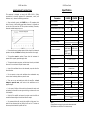
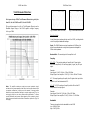
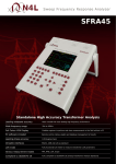
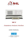
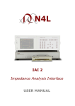
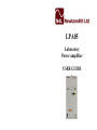
LPA05
Laboratory
Power amplifier
USER GUIDE
LPA05 User Guide
LPA05 User Guide
Warranty
LPA05
This product is guaranteed to be free from defects in materials and
workmanship for a period of 36 months from the date of purchase.
High frequency, high power, dc accurate, power amplifier for
laboratory and industrial applications.
Description
LPA05 is a wideband power amplifier with ±40V peak voltage output at
3A rms from dc to 500kHz. At lower output levels, the gain extends
beyond 1MHz. It uses an innovative balanced high frequency design to
give a slew rate of greater than 120V/us, while maintaining dc
accuracy and high reliability.
In the unlikely event of any problem within this guarantee period, first
contact Newtons4th Ltd. or your local representative, to give a description
of the problem. If the problem cannot be resolved directly then you will
be given an RMA number and asked to return the unit. The unit will be
repaired or replaced at the sole discretion of Newtons4th Ltd.
This guarantee is limited to the cost of the LPA05 itself and does not
extend to any consequential damage or losses whatsoever including, but
not limited to, any loss of earnings arising from a failure of the product.
In the event of any problem with the equipment outside of the guarantee
period, Newtons4th Ltd. offers a full repair service – contact your local
representative.
LPA05B is a higher current, lower voltage version capable of delivering
5A rms from dc to 1MHz at ±16V peak.
The LPA05 does not require any calibration.
LPA05 is generally stable driving any load - resistive, capacitive (see
note) or inductive – but as with all high frequency amplifiers, care
must be taken when connecting to pure capacitive loads. An
appropriate resistor or inductor may be needed in series with the
capacitive load to minimise peaking in the frequency response or to
prevent spurious oscillation.
Note: Newtons4th Ltd. shall not be liable for any consequential
damages, losses, costs or expenses arising from the use or misuse of
this product however caused.
LPA05 is powered by a universal input power supply monitored by a
pair of indicators on the front panel. Internally the LPA05 is floating
from ground to minimise earth loops, but can be grounded by linking
the output 0V to earth via the 4mm connectors.
Declaration of Conformity
LPA05 is housed in a robust steel cabinet.
89/336/EEC relating to electromagnetic compatibility:
EN 55022 Class A
Do not obstruct the ventilation holes on the sides, underneath
or rear of the amplifier.
Newtons4th Ltd
30 Loughborough Road
Mountsorrel
Loughborough
LE12 7AT, UK
Tel +44 116 2301066
Fax +44 116 2301061
E-mail [email protected]
Website www.newtons4th.com
We, Newtons4th Ltd, declare that the product LPA05 conforms to the
requirements of Council Directives:
73/23/EEC relating to safety of laboratory equipment:
EN 61010-1
November 2005
Eur Ing Allan Winsor BSc CEng MIEE
(Director of Newtons4th Ltd)
LPA05 User Guide
LPA05 User Guide
IMPORTANT SAFETY INSTRUCTIONS
Specification
This equipment is designed to comply with BSEN 61010-1 (Safety
requirements for electrical equipment for measurement, control, and
laboratory use) – observe the following precautions:
•
When continually running the LPA05A into a <5Ω impedance load
refer to Current v Load De-rating graph below. However, it is allowable to
run the unit at full current into <5Ω for a period not exceeding 30 seconds,
otherwise overload damage may occur.
Parameter
LPA05A
Input connector
isolated BNC
Input impedance
10k
Peak operational input voltage
±4
•
This appliance must be earthed. Ensure that the instrument is
powered from a properly grounded supply outlet.
•
The input and output connectors, and the internal circuitry are isolated
from earth - do not exceed ±40V peak common mode.
Units
Ω
±1.6
V
Maximum safe input voltage
±15
V
Peak withstand input voltage
±30
V
Input common mode range
±40
V
1
5
mV (typ)
mV (max)
Input offset voltage
•
Ensure that the supply voltage agrees with the rating of the instrument
printed on the back panel before connecting the mains cord to the supply.
LPA05B
Full power bandwidth
Small signal bandwidth (-3dB)
Coupling
1M
@40V pk-pk
250k
@80V pk-pk
1M
@36V pk-pk
Hz
3M @2V pk-pk
X10
isolated BNC
isolated 4mm
•
Keep all the ventilation holes on the underneath, rear, and sides free
from obstruction.
Output connectors
•
Do not operate or store under conditions where condensation may
occur or where conducting debris may enter the case.
Maximum safe output level
•
There are no user serviceable parts inside the amplifier – do not
attempt to open the case, refer service to the manufacturer or his
appointed agent.
Maximum ac output current
(>10Hz)
•
In the event of a failure of the mains fuse, disconnect the mains cord
and replace the fuse with the same type and rating, as shown on the rear
of the amplifier.
Temperature range
Size
Weight (approx)
•
Switch off the amplifier and ensure the output current has fallen to
zero before disconnecting an inductive load from the output.
Power source
•
We recommend that after running the amplifier at high power for a
period of time disconnect the load, letting the fan run for 10 minutes to
remove any latent heat build up within the unit.
Notes:
All specifications are typical values unless otherwise stated.
Specifications are valid after 30 minutes warm up.
±40
Power consumption (max)
±16
90
Slew rate
Maximum dc output current
Hz
Ac, ac+dc, ac+(dc)
Gain
Peak output voltage
Hz
VA
120
3
5
2
V
V/us
5
8
4
0 - 40
30 x 15 x 25
6
90-265
A rms
A pk
A dc
°C
cm
Kg
V
45-63
Hz
150
VA (max)
LPA05 User Guide
LPA05 User Guide
Total Harmonic Distortion:
For frequencies up to 1MHz, Total Harmonic Distortion is typically less
than 0.6% for the LPA05A and 0.5% for the LPA05B.
This graph demonstrates the effect of Total Harmonic Distortion on the
Maximum Output Voltage of the LPA05 amplifier at higher frequency
levels up to 1MHz.
Fig 1 (Distorted current waveform)
Fig 2 (Correct current waveform
Quick User Guide
In the following text we describe the use of the LPA05, including details
on the Coupling and bandwidth settings.
Input: The LPA05A features an input impedance of 10kOhms; this
should be considered when using function generators designed for
50Ohm load impedance.
Nominal Gain: The nominal gain of the amplifier is x10
Coupling:
AC + (DC) – This coupling setting will amplify the AC signal at the
input of the amplifier by x10 and simply pass (x1 gain) any DC input
signal.
Example:
Input signal: 1V AC @ 10 kHz + 500mV DC offset
Output Signal: from amplifier: 10V AC @ 10 kHz + 500mV DC offset
AC – This coupling setting will amplify the AC signal at the input of the
amplifier by x10 and attenuate the DC.
Note: The amplifier contains an output rms current protection circuit,
and when driving some capacitive loads this circuit may be activated. Due
to capacitor construction, at high current the amount of energy transfer
distorts the current waveform resulting in excessive peak current (Fig 1 on
next page), whilst the rms value remains within specification. To ensure
correct functionality and prevent false triggering of the protection circuit,
ideally the current waveform should be a sinewave as pictured in (Fig.2 on
next page).
AC + DC – AC+DC coupling will amplify both the AC and the DC
components of the input signal.
Example:
Input signal: 500mV AC @ 10 kHz + 500mV DC offset
Output Signal: from amplifier: 5V AC @ 10 kHz + 5V DC offset
Bandwidth:
There are two options for the bandwidth on the LPA05
Low: -3dB @ 85 kHz
High: -3dB @ 1MHz