1
SLM3505
USER MANUAL
“Do not be hasty when making measurements.”
The SLM3505 is a precision instrument that provides you with
the tools to make a wide variety of measurements accurately,
reliably, and efficiently - but good metrology practice must be
observed. Take time to read this manual and familiarise
yourself with the features of the instrument in order to use it
most effectively.
DANGER OF ELECTRIC SHOCK
Only qualified personnel should install this equipment,
after reading and understanding this user manual. If in
doubt, consult your supplier.
RISQUE D'ELECTROCUTION
L'installation de cet équipement ne doit être confiée qu'à
un personnel qualifié ayant lu et compris le présent
manuel d'utilisation. Dans le doute, s'adresser au
fournisseur.
GEFAHR VON ELEKTRISCHEM SCHOCK
Nur entsprechend ausgebildetes Personal ist berechtigt,
diese Ausrüstung nach dem Lesen und Verständnis
dieses Anwendungshandbuches zu installieren. Falls Sie
Zweifel haben sollten, wenden Sie sich bitte an Ihren
Lieferanten.
RISCHIO DI SCARICHE ELETTRICHE
Solo personale qualificato può installare questo
strumento, dopo la lettura e la comprensione di questo
manuale. Se esistono dubbiconsultate il vostro
rivenditore.
PELIGRO DE DESCARGA ELÉCTRICA
Solo personal cualificado debe instalar este instrumento,
después de la lectura y comprensión de este manual de
usuario. En caso de duda, consultar con su
suministrador.
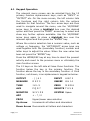
IMPORTANT SAFETY INSTRUCTIONS
This equipment is designed to comply with BSEN 61010-1
(2001) (Safety requirements for electrical equipment for
measurement, control, and laboratory use) – observe the
following precautions:
Ensure that the supply voltage agrees with the rating of the
instrument printed on the back panel before connecting the
mains cord to the supply.
This appliance must be earthed. Ensure that the instrument
is powered from a properly grounded supply.
The inputs are rated at 1kV rms or dc cat II; 600V rms or dc
cat III. Do not exceed the rated input.
Keep the ventilation holes on the underneath and rear free
from obstruction.
Do not operate or store under conditions where
condensation may occur or where conducting debris may
enter the case.
There are no user serviceable parts inside the instrument –
do not attempt to open the instrument, refer service to the
manufacturer or his appointed agent.
Newtons4th reserves the right to make changes to this
document or the product it describes at any time,
without notice, and without a commitment to update the
contents of this particular document.
Note: Newtons4th Ltd. shall not be liable for any
consequential damages, losses, costs or expenses
arising from the use or misuse of this product however
caused.
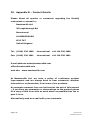
DECLARATION OF CONFORMITY
Manufacturer:
Newtons4th Ltd.
Address:
30 Loughborough Rd.
Mountsorrel
Loughborough
LE12 7AT
UK
We declare that the product:
Description:
Selective Level Meter
Model:
SLM3505
Conforms to the requirements of Council Directives:
89/336/EEC relating to electromagnetic compatibility:
EN 61326:1997 Class A
73/23/EEC relating to safety of laboratory equipment:
EN 61010-1
April 2006
Eur Ing Allan Winsor BSc CEng MIEE
(Director Newtons4th Ltd.)
WARRANTY
This product is guaranteed to be free from defects in materials
and workmanship for a period of 36 months from the date of
purchase.
In the unlikely event of any problem within this guarantee
period, first contact Newtons4th Ltd. or your local
representative, to give a description of the problem. Please
have as much relevant information to hand as possible –
particularly the serial number and release numbers (press
SYSTEM then LEFT arrow key).
If the problem cannot be resolved directly then you will be
given an RMA number and asked to return the unit. The unit
will be repaired or replaced at the sole discretion of
Newtons4th Ltd.
This guarantee is limited to the cost of the instrument itself and
does not extend to any consequential damage or losses
whatsoever including, but not limited to, any loss of earnings
arising from a failure of the product or software.
In the event of any problem with the instrument outside of the
guarantee period, Newtons4th Ltd. offers a full repair and recalibration service – contact your local representative. It is
recommended that the instrument be re-calibrated annually.
Table of Contents
1
INTRODUCTION ........................................................................................................................ 3
1.1
Manual Layout and Content ......................................................................................... 3
1.2
Instrument Functions...................................................................................................... 4
1.3
Instrument Features ....................................................................................................... 5
1.4
Application Overview ...................................................................................................... 6
2
SAFETY ........................................................................................................................................ 7
3
GETTING STARTED ................................................................................................................. 8
3.1
Unpacking the Instrument ............................................................................................ 8
3.2
Power Sources and Communications........................................................................ 9
3.3
Instrument Controls and Connections ................................................................... 11
4
INSTRUMENT OVERVIEW ................................................................................................... 12
4.1
Keypad Operation........................................................................................................... 14
4.2
Getting started with Initial signal capture ............................................................ 15
5
OUTPUT KEY ............................................................................................................................. 17
5.1
6
Genrator Menu Functions ............................................................................................ 18
INPUT KEY ................................................................................................................................. 20
6.1
7
Input Menu Functions ................................................................................................... 21
MEASURE KEY .......................................................................................................................... 23
7.1
(SLM) Mode measurment menu functions............................................................ 24
7.2
(LCR) Mode measurement menu functions .......................................................... 26
7.3
(VSWR) Mode measurement menu functions ..................................................... 27
7.4
(FRA) Mode measurement menu functions .......................................................... 28
7.5
Oscilloscope Mode.......................................................................................................... 29
8
SWEEP KEY ............................................................................................................................... 32
8.1
9
Sweep Menu Functions................................................................................................. 33
TUNE KEY .................................................................................................................................. 36
9.1
10
Tune Menu Functions .................................................................................................... 37
ZERO KEY .............................................................................................................................. 38
10.1 Zero Key Displays ............................................................................................................ 38
11
AUX KEY ................................................................................................................................. 41
12
REMOTE KEY......................................................................................................................... 42
12.1 Remote Key Functions ................................................................................................... 43
13
MONITOR KEY ...................................................................................................................... 44
Page | 1
Newtons4th Ltd
SLM3505 User Manual
14
SYSTEM KEY ......................................................................................................................... 45
14.1 System Key Functions.................................................................................................... 46
15
APP KEY .................................................................................................................................. 49
15.1 App Key Functions & menus ........................................................................................ 49
16
PROG KEY .............................................................................................................................. 51
16.1 Prog Key Functions.......................................................................................................... 52
16.2 Example Sweep Results Store/Recall Process ...................................................... 53
16.2 Storing Results.................................................................................................................. 54
16.3 Recalling Results .............................................................................................................. 55
16.4 Deleting Results................................................................................................................ 56
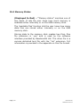
16.4 Memory Status .................................................................................................................. 57
17
SELECTIVE LEVEL METER (SLM) MODE ..................................................................... 58
17.1 (SLM) Screen Display Areas ........................................................................................ 59
17.2 Example (SLM) Carrier Frequency Test .................................................................. 60
17.3 Example (SLM) Audio Tone Test ................................................................................ 60
17.4 Example (SLM to SLM) Passive Sweep Check ...................................................... 60
18
IMPEDANCE METER (LCR) MODE ................................................................................. 64
18.1 (LCR) Screen Display Areas ......................................................................................... 65
18.2
Example (LCR) Line Trap Test ............................................................................... 66
18.3
Example (LCR) Line Trap Sweep Test ................................................................ 67
18.4
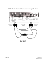
Example basic impedance (Capacitance) test setup .................................... 69
19
VOLTAGE STANDING WAVE RATIO (VSWR) MODE .............................................. 71
19.1
(VSWR) Screen Display Areas ............................................................................... 72
19.2
Example (VSWR) Impedance Method Test....................................................... 73
19.3
Example (VSWR) Direct Coupler Method Test ............................................... 74
19.4
Example (VSWR) Sweep Test ................................................................................ 76
20
FREQUENCY RESPONSE ANALYSER (FRA) MODE .................................................. 77
20.1
(FRA) Screen Display Areas ................................................................................... 78
20.2
Example (FRA) Test ................................................................................................... 79
21.1
Bit Error Rate ............................................................................................................... 81
21.2
Theory of Operation .................................................................................................. 82
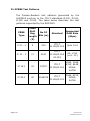
21.3
PRBS Test Patterns .................................................................................................... 83
21.4
BER Send Mode ........................................................................................................... 84
21.5
BER Transmit Mode ................................................................................................... 84
Page | 2
Newtons4th Ltd
SLM3505 User Manual
21.6
BER Test Mode............................................................................................................. 84
21.7 BER Test Setup ................................................................................................................. 86
21.8 Measure Menu ................................................................................................................... 86
21.9
(BER) Screen Display Area ..................................................................................... 87
21.10 (BER) Keypad Operation ............................................................................................ 87
22
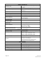
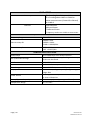
Technical Specification ..................................................................................................... 88
23.
Appendix A – Text File Format ...................................................................................... 91
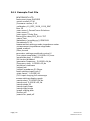
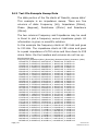
24.1
Example Text File ....................................................................................................... 92
24.2
Text File Header Format Explanation ................................................................. 93
24.3
Text File Example Sweep Data.............................................................................. 94
25.
Appendix B – Contact Details ........................................................................................ 96
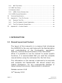
1 INTRODUCTION
1.1 Manual Layout and Content
The layout of this manual is in a manner that introduces
the SLM3505 to the user and helps with the familiarization
and understanding of the functionality, application,
features, menues and performance of the instrument.
While it is possible to use the manual to review specific
functions, it is recommended that you read the complete
manual before using the instrument for the first time.
The information in this manual is believed to be accurate
and complete but Newtons4th Ltd cannot accept any
liability whatsoever, for any consequential damage or
losses arising from errors, inaccuracies or omissions.
Release revision 2.65
16th January 2012
Page | 3
Newtons4th Ltd
SLM3505 User Manual
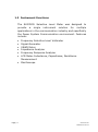
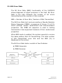
1.2 Instrument Functions
The SLM3505 Selective Level Meter was designed to
provide a single instrument solution for multiple
applications in the communication industry and specifically
the Power System Communication environment. Features
include:
Page | 4
Frequency Selective Level Voltmeter
Signal Generator
VSWR Meter
Impedance Analyzer
Frequency Response Analyzer
LCR Meter-Inductance, Capacitance, Resistance
Measurement
Oscilloscope
Newtons4th Ltd
SLM3505 User Manual
1.3 Instrument Features
The instrument is housed in a rugged aluminum case and
is provided with various accessories together with an
optional carry case as standard.
The instrument has a state of the art 5.7” (150mm) Color
Display to maximize visibility in all conditions, including
full sunlight. Its overall size is (12”x 9”x 1.75”) (310mm
x 225mm x 45mm) and relatively light weight (5lbs)
(2.3Kg) The SLM3505 operates off internal rechargeable
batteries, an AC/DC power source or an external 12V
vehicle battery.
Further Features Include:
Page | 5
Up to 1000 analyzer setups, readings and sweep
results can be stored
On board real time clock
Full colour display
6 digit freq, 5 digit volts and 4 digit dBm resolution
Operational temperature range -5 to +50°C
1GB internal flash storage and ports. Many of the
instrument test functions will provide the user with
valuable information. Therefore 1 Gigabyte of memory,
an external USB port and an RJ45 input connection for
laptop connectivity provides a versatile solution for
storage and communication.
Newtons4th Ltd
SLM3505 User Manual
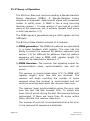
1.4 Application Overview
This section provides a short overview of where the
instrument applications are more commonly used. Some
uses are explained in more detail and provide an incite
into the flexibility of the instrument.
Power Line Carrier Alignment & Maintenance
Line Trap Testing
Line Tuner Testing
PLC Transmitter & Receiver Test & Set-up
Audio Tone Protection Relay Channel Test & Setting
Transmitter/Receiver Testing
The instrument has a wide frequency range (5Hz to 5MHz)
and is ideal for checking transmitters and receivers on
Power Line Carriers, Audio Tone or Analog Baseband
Microwave systems. The SLM3505 scans the required
frequency range then centre‟s automatically on the largest
or two largest signal peaks, easily detecting the carrier
frequencies. It is also ideal for work on audio tone and
microwave systems.
Line Trap testing
The instrument can plot an impedance verses frequency
graph directly on the display. Therefore the user can view
a pictorial representation of the resonant frequency and
make adjustments while viewing the changes in a real
time environment.
Line Tuner Testing
The instrument provides the solution for adjusting a Line
Tuner‟s Series inductor and Impedance Matching
transformer, for minimum reflected power.
This is achieved with a directional coupler or using an
innovative impedance measurement technique.
Page | 6
Newtons4th Ltd
SLM3505 User Manual
2
SAFETY
READ THIS GUIDE AND SAFETY INFORMATION
BEFORE USING THE INSTRUMENT.
Only use the instrument under the conditions and
purpose for which it is intended.
Ensure that the AC supply Voltage and the power
pack supplied are at the same ratings. AC operation
is intended for indoor use only.
This instrument is NOT “field” repairable (with the
exception of battery replacement). Return the unit
to Newtons4th Ltd for repair or replacement.
Use only batteries recommended within this guide.
Refer to battery information under the “Getting
Started”, section of this manual. NOTE: Proper antistatic procedures should be used when opening the
instrument to change the batteries, such as a
grounding strap.
The instrument is NOT waterproof or airtight. Return
to the factory for evaluation if exposed to abnormal
environmental conditions.
Do not operate or store under conditions where
condensation may occur or where conducting debris
may enter the case.
Keep the ventilation holes on the top and bottom
ends of the instrument clear.
NOTE: Operators should follow all standard and
specific company safety procedures when using this
product and accessories. Special precautions must
be adhered to when working with or around
antennas, power lines, radio frequency sources, etc.
FAILURE TO COMPLY WITH SAFETY RULES MAY
RESULT IN INJURY OR DEATH.
When using this instrument, access to other products
or system parts may be needed. Read and follow
the safety instructions of all utilized components.
Page | 7
Newtons4th Ltd
SLM3505 User Manual
3
GETTING STARTED
3.1 Unpacking the Instrument
The instrument was dispatched in a custom designed
shipping container.
Upon receipt of the equipment,
inspect all packaging for visual damage. If any damage is
indentified, report immediately to Newtons4th Ltd so the
carrier may be notified. If the packaging damage is
noticeable while the delivery person is present, obtain a
written statement from the carrier.
Page | 8
Newtons4th Ltd
SLM3505 User Manual
3.2 Power Sources and Communications
The instrument can be powered by multiple sources;
directly from the AC/DC Adapter, from the internal battery
source (Lithium polymer batteries) or directly through the
DC input, (9-18V @ 3A source required). The instrument
is shipped with a 6 meter power adapter lead that permits
use through a vehicle DC source outlet socket.
AC/DC Adapter – The AC/DC adapter can accept a wide
AC input range (100 to 240Vac).
Adapter plugs are
available to accommodate the various country standards.
Battery Power – The instrument is shipped with a
battery source consisting of (3) lithium polymer
rechargeable batteries. They are secured into the battery
compartments with tie-wraps.
DC Input – The instrument is supplied with a 6 meter
vehicle power adaptor lead. The vehicle DC source outlet
socket can then be used to power and charge the
instrument. The DC input will operate with a 9-18V dc
source at 3A; however the equipment warranty does not
cover any damage caused by any other source than the
ones provided with this instrument.
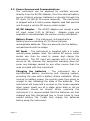
Charging the batteries – The instrument has a
sophisticated battery monitoring and charging system,
providing the user with a battery status indication. When
running on battery power, the monitor goes from green to
orange to red, indicating the state of the batteries. The
instrument will beep and a prompt on the screen appears
when power levels are at a stage when data or set-up
information should be stored. When receiving the
instrument it is recommended that the batteries are first
charged and fully discharged two or three times to help
extend battery life. Finally fully charge the batteries
before using the instrument
Page | 9
Newtons4th Ltd
SLM3505 User Manual
The system provides the following indications while the
batteries are charging:
When charging - blue with >>>>.
When finished charging, but power connected- blank.
If batteries get too hot, charging is suspended - red
with XXXX
Changing the batteries - Only qualified personnel,
trained and knowledgeable in electronic instrument repair
and safety, having read this guide should attempt to
change the batteries.
Disconnect the instrument from all external power
sources. Remove the four (4) hex bolts from the sides of
the instrument housing (2 on each side). NOTE: Proper
anti-static precautions should be used when opening the
instrument, such as a grounding strap.
Note the position and location of all ribbon cables.
Disconnect ribbon cables as necessary to securely rest the
instrument cover face down. Cut the tie-wraps holding
the batteries in and remove all of the old batteries.
NOTE: All three batteries should be replaced at the same
time. Make sure disposal of the used batteries is in
accordance with the local country regulations. Make sure
the batteries are first charged and fully discharged two or
three times to help extend battery life. Then finally fully
charge the new batteries before using the instrument.
Communications – The instrument has communication
interface ports supporting USB, RS232 and LAN options.
Page | 10
Newtons4th Ltd
SLM3505 User Manual
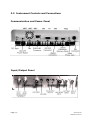
3.3 Instrument Controls and Connections
Communication and Power Panel
Input/Output Panel
Page | 11
Newtons4th Ltd
SLM3505 User Manual
4
INSTRUMENT OVERVIEW
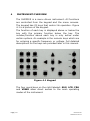
The SLM3505 is a menu driven instrument. All functions
are controlled from the keypad and the menu screens.
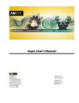
The keypad has 23 keys that control its operation. Figure
4-1 is a picture of the keypad.
The function of each key is displayed above or below the
key with the primary function below the key. The
number/function above each key is only active under
certain options. An example is the numeric keys which are
for entering a specific frequency or voltage. Full detailed
descriptions for the keys are provided later in this manual.
Figure 4.1 Keypad
The four round keys on the right labeled: SLM, LCR, FRA
and VSWR allow direct access to the main operating
modes of the instrument.
Page | 12
Newtons4th Ltd
SLM3505 User Manual
SLM – Selective Level Meter – Selects the Selective Level
Meter Mode.
LCR – Impedance Analyzer - Selects the Impedance
Analyzer Mode.
FRA – Frequency Response Analyzer - Selects the
Frequency Response Analyzer Mode.
VSWR – Standing Wave Ratio – Selects the voltage
Standing Wave Ratio Mode.
The four main Mode keys „SLM‟, „LCR‟, „FRA‟ and „VSWR‟
have a second function. The letter above each key is a
numeric multiplier „M‟ for mega, „K‟ for kilo, „m‟ for milli
and „µ‟ micro. When entering large or small numbers
these multipliers may be used to save key strokes.
By pressing the relevant Mode button twice allows the
menu screens to appear. Accessing the menu functions
using the “keypad Operation” is described in section 4.1.
Pressing the HOME/ESC button reverts back to the main
function screen.
Page | 13
Newtons4th Ltd
SLM3505 User Manual
4.1 Keypad Operation
The relevant menu screen can be selected from the 12
primary function alphanumeric keys, such as “INPUT” or
“OUTPUT” etc. On the menu screen, the left column lists
the functions and the right column lists the options
available for that function. The four arrow keys are then
used to navigate around the menu, use the „UP/DOWN‟
arrow keys to place a highlight box over the desired
option and then press the „RIGHT‟ arrow key to select and
show any further options available. Use the „UP/DOWN‟
arrow keys again to place a highlight box over the
relevant option and then press the “ENTER” key.
Where the column selection has a numeric value, such as
voltage or frequency, the „LEFT/RIGHT‟ arrow keys are
used together with the (secondary function) number and
letter keys to adjust the value. When the new value has
been set press the “ENTER” key.
Press the HOME/ESC key at any time to abort the present
activity and revert to the previous menu or ultimately the
main function screen.
The 12 keys on the left side all have three functions. The
function below the key is the primary function. The
function above the key is the secondary function. A third
function, not shown, is an alphanumeric keypad as below:
OUTPUT
.()#1
INPUT
ABC2
MEASURE
DEF3
SWEEP
GHI4
TUNE
JKL5
ZERO
MNO6
AUX
PQR7
REMOTE T U V 8
MONITOR
WXYZ9
SYSTEM Space
APP
+-*/0
PROG
Upper/Lower case selection
Up Arrow
Increments all letters and characters
Down Arrow Decrements all letters and characters
Page | 14
Newtons4th Ltd
SLM3505 User Manual
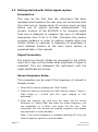
4.2 Getting started with Initial signal capture
Introduction
This may be the first time the instrument has been
operated and therefore the user may not be familiar with
the initial set up. Always allow 30 minutes warm up time
before use to ensure accurate measurements. The
primary function of the SLM3505 is for checking signal
lines and is designed to measure the level of individual
frequencies from 5 Hz to 5 MHz. Therefore this section
provides guidance in order to capture signals which are
initially known or unknown in frequency or amplitude. A
more detailed function of the main menu options is
explained later in this manual.
Signal Connection
The signal line should initially be connected to the ±300v
input, as it may not be known what amplitude of signal is
expected. This will safeguard the instrument until the
exact amplitudes are known.
Known frequency Setup
This procedure can be used if the frequency of interest is
already known.
1. Select SLM mode by pressing the “SLM” button
2. Press the input key and from the menu set the input to “high z”,
Scale factor to +1.0000 and CH1 input ranging to “full
autorange”.
3. Press the measure key and from the menu set the centre
frequency to “single fixed” and enter the known frequency, set
the bandwidth to “3.1KHz” and press the Esc key. (The
instrument will look around the entered frequency and display
the amplitude in Volts and dBm).
Note: if the source frequency is unstable selecting AFC from the
centre frequency options is recommended.
Page | 15
Newtons4th Ltd
SLM3505 User Manual
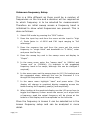
Unknown frequency Setup
This is a little different as there could be a number of
frequencies on the line and a decision will be required as
to which frequency is to be selected for measurement.
Therefore an initial sweep across a frequency band is
initialized to show what frequencies are present. This is
done as follows:
1. Select SLM mode by pressing the “SLM” button
2. Press the input key and from the menu set the input to “high
z”, Scale factor to +1.0000 and CH1 input ranging to “full
autorange”.
3. Press the measure key and from the menu set the centre
frequency to “single fixed” and bandwidth to “3.1KHz”, enter
and press the Esc key.
4. Press the sweep key and in the sweep menu set display to
“Graph”.
5. In the same menu enter the “sweep start” to (10KHz) and
“sweep end” to (500KHz). (In brackets is the suggested
frequency band to be swept, although this can be changed if
required).
6. In the same menu set the sweep steps to (40) (In brackets are
the suggested steps, although this can be increased if it is
thought all frequencies are not being seen).
7. In the same menu highlight “start” and press enter. (The
display will change to graphical display sweeping across the
band showing the frequency peak(s) and amplitude).
8. When looking at the graphical display use the L/R arrow keys to
toggle the frequency cursor across the screen, as it aligns with
a frequency peak the actual frequency will be shown at the
bottom of the display and the amplitude on the Left side.
Once the frequency is known it can be selected as in the
known frequency setup and can be analyzed in more
detail.
Page | 16
Newtons4th Ltd
SLM3505 User Manual
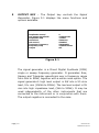
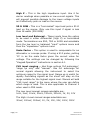
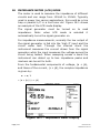
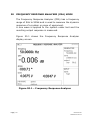
5
OUTPUT KEY – The Output key controls the Signal
Generator. Figure 5.1 displays the menu functions and
options available.
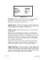
GENERATOR SETTINGS
amplitude control
low output amplitude
amplitude step
waveform
fsk control
generator frequency
frequency step
output
V
2.0000Vrms
1.1000
sinewave
disabled
50.0000Hz
2.00000 times
Off
Figure 5.1
The signal generator is a Direct Digital Synthesis (DDS)
single or sweep frequency generator. It generates Sine,
Square and Triangular waveforms over a frequency range
from 5Hz to 5MHz, together with a white noise option. The
signal generator‟s high level output is 2W into a 50 ohm
load, 10v rms (10KHz to 5MHz). The low level output is 5V
rms into high impedance load, (5Hz to 5MHz). It may be
used independently of the other instruments that are
connected to the instrument or in conjunction with them.
The output negative is connected to the case.
Page | 17
Newtons4th Ltd
SLM3505 User Manual
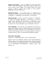
5.1 Genrator Menu Functions
“Amplitude Control” – Has three options: “V, dBm or
dBu” and controls how „amplitude‟ and „amplitude step‟ is
displayed on the screen. Amplitude is displayed either in
Volts, dBm or dBu and is adjusted using the “low output
amplitude”, “high output amplitude” or “amplitude step”
menu function. Amplitude step is set in either volts or db
times the step value. The amplitude step can be set as
small as one millivolt or 0.001 dBm. The values can be
changed by following the “Keypad Operation” instructions
in section 4.1. (Once the step has been set, using the
up/dn arrow keys with the main display will
increase/decrease the amplitude by the step factor).
Waveform – Has four options: “sinewave, triangle,
squarewave and white noise”. The use and selection of the
different waveforms is dependent on user need. The
sinewave is used for power line carrier testing.
FSK Control - FSK (Frequency Shift Keying) has two
options “disabled and enabled” and can be used to check
the loss of guard timers in Transfer Trip equipment.
Enabling this option adds “Frequency 0”, “frequency 1”
and “guard time” to the left menu functions. This allows a
“0” frequency and a “1” frequency to be entered together
with a guard time so the delay between the frequencies
can be checked. The “0” “1” Frequency and guard time
can be entered in the options menu by following the
“Keypad Operation” instructions in section 4.1.
Note: The “guard time” function is not operational
at this time. A firmware upgrade will enable this
function.
Page | 18
Newtons4th Ltd
SLM3505 User Manual
Generator Frequency - This function determines the
generator output frequency. The “Frequency Step”
function determines the multiple amount the frequency
changes when required to step up or step down. The
“Step type” can be either set for linear or logarithmic
depending on user preference. Settings for these options
can be entered by following the “Keypad Operation”
instructions in section 4.1. (Once the step has been set,
using the L/R arrow keys with the main display will
increase/decrease the generator by the step factor).
*Note: If the generator is off, when using the L/R
arrows the frequency changes on the main display, if the
generator is on the frequency changes in the generator
window only.
Output – This controls the relevant output connection
and has three options: “off, low and high”. When the high
level output is selected the impedance is fixed at 50Ω
(75Ω optional). However, selecting the “low” output adds
another function to the left menu, “Output Impedance”
This function allows the right menu options of 50Ω, 75Ω
or 600Ω output impedance to be selected.
Page | 19
Newtons4th Ltd
SLM3505 User Manual
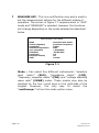
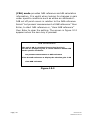
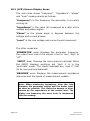
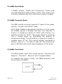
6
INPUT KEY – This controls the signal input connections,
the menu has three functions, “input”,” scale factor” and
“CH1 input ranging”. These options are in all modes
however an additional CH2 input ranging function is
available in “FRA” mode. Figure 6.1 displays this screen.
INPUT SETTINGS
input
high Z
scale factor
+1.0000
CH1 input ranging 1.1000
Figure 6.1
Page | 20
Newtons4th Ltd
SLM3505 User Manual
6.1 Input Menu Functions
Input – Has four options from the right menu, “high Z”,
“50Ω 18W” (75Ω optional), “low level” and “balanced”.
The “high Z” input is the default, max ±300v Pk, 1MΩ
impedance whilst the “50Ω 18W” input is max 30v rms.
The “low level” input, max ±10v Pk which, when selected
adds “impedance” to the left menu functions. This allows
options of “high impedance” (1MΩ), “50Ω”, “75Ω”, and
“600Ω”, to be entered.
The “balanced” input, which has three 4mm connectors
(positive, negative and ground), is a differential type, max
±10v Pk and a selectable impedance the same as the low
level input.
The “Channel 2” input is max ±10v Pk fixed at 1MΩ
impedance.
WARNING:
The low voltage inputs, (BALANCED INPUTS, Low Level 50Ω
18W and CH2) are rated at ±10V pk maximum voltage.
Applying a higher voltage will damage the input(s)
requiring factory repair. Use the low voltage input(s) only
after confirming the input signal will not exceed the
maximum rating.
Meter Inputs – Refer to section 3.4 (Instrument controls
and Connections), which shows the input connector
orientation. Each input has a red LED, the LED that is
“ON” will be next to the active input. The high Z, low level
and balanced inputs are differential inputs they effectively
put no load on the signal being measured. The 50Ω 18W
input can be used to accept transmitters etc as this input
provides termination. The „high Z‟ input should be used
when measuring RF carrier signals or signals that require
minimal loading. All inputs are isolated from ground.
Page | 21
Newtons4th Ltd
SLM3505 User Manual
High Z - This is the high impedance input. Use it for
carrier readings when possible or low current signals. This
will prevent possible damage to the lower voltage inputs
as it affectively puts no load on the source.
50 Ω 18W - This is a “terminated” input and puts a 50 Ω
load on the source. Only use this input if signal is less
than 18 watts (30V RMS).
Low level and Balanced - These inputs have the option
to be used in either differential (high Z) or terminated
mode. Terminations are 50Ω, 75Ω or 600Ω and selectable
from the low level or balanced “input” options menu and
then the “impedance” options menu.
Scale Factor - This option is used to compensate for an
attenuator or a scope probe. If using a X10 probe, putting
„10‟ in as the scale factor gives the correct value for
voltage. The settings can be changed by following the
“Keypad Operation” instructions in section 4.1.
CH1 input ranging – Has three options „full autorange‟,
„range up only‟ and “manual”. Use full autorange for
normal signals allowing the instrument to select the
optimum range for the signal level. Range up is useful for
rapidly fluctuating signals as the shunt will stay on the
range suitable for the highest signal level. Manual will add
“CH1 input range” to the menu where the user can define
which range is used. This is also applicable to Channel 2
when used in FRA mode.
The Low Level manual ranges selectable are:
1mV, 3mV, 10mV, 30mV, 100mV, 300mV, 1V, 3V, 10V
The High z Level manual ranges selectable are:
30mV, 100mV, 300mV, 1V, 3V, 10V, 30V, 100V, 300V
Page | 22
Newtons4th Ltd
SLM3505 User Manual
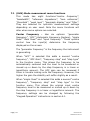
7
MEASURE KEY– This is a multifunction key and is used to
set the measurement options for the different modes of
operation. The screen in Figure 7.1 appears when in “SLM”
mode and “MEASURE” is selected. However the functions
will change depending on the mode selected as described
below.
MEASUREMENT SETTINGS
Mode
centre frequency
bandwidth
reference impedance
zero reference
threshold
peak level
bargraph display
filter
selective level meter
generator frequency
100Hz
50Ω
+0.000dBm
-50.00 dBm
off
off
normal
Figure 7.1
Mode – Can select five different instruments: “selective
level meter” (SLM), “impedance meter” (LCR),
“frequency response meter” (FRA) and “voltage standing
wave ratio” (VSWR) meter. These modes may also be
selected by the four round keys on the right-side of the
keypad. However, the only way to select the
“oscilloscope” is from the mode option menu.
Page | 23
Newtons4th Ltd
SLM3505 User Manual
7.1 (SLM) Mode measurment menu functions
This mode has eight functions:“centre frequency”,
“bandwidth”, “reference impedance”, “zero reference”,
“threshold”, “peak level”, “bargraph display” and “filter”.
They are selected for optimum measurement settings
depending on user need. Note the menu functions will
alter when some options are selected.
Center Frequency - Has six options: “generator
frequency”, “AFC” (Automatic Frequency Capture), “single
fixed” “dual fixed” and “input frequency”. These options
control how the input(s) determine the frequency
displayed on the screen.
The “generator frequency” is the frequency the instrument
is generating.
When “AFC” is selected this adds a second “centre
frequency”, “AFC Gain”, “frequency step” and “step type”
to the function menu. This allows the frequency to be
automatically centered and the level to be measured or
moved up or down by the step frequency in a linear or
logarithmic amount. The AFC gain can be increased if
there is trouble locking onto the frequency. However, the
higher the gain the stability will suffer slightly as a result.
When “single fixed” is selected this adds a second “centre
frequency”, “frequency step” and “step type” to the
function menu. This allows the original input centre
frequency level to be measured or moved up or down by
the step frequency in a linear or logarithmic amount. The
frequency settings can be changed by following the
“Keypad Operation” instructions in section 4.1.
Page | 24
Newtons4th Ltd
SLM3505 User Manual
When “dual fixed” is selected this removes the second
“centre frequency”, “frequency step” and “step type”
function and replaces them with “centre frequency 1” and”
centre frequency 2”. This allows the levels at the two set
frequencies to be measured. The two option frequencies
can be changed by following the “Keypad Operation”
instructions in section 4.1.
The “input frequency” is the frequency of the input signal
and is usually used when a clean spot frequency is known.
bandwidth – Has nine options:“wide”, “3.1KHz”,
“1.95KHz”, “600Hz”, ”400Hz”, ”360Hz”, “100Hz”, “25Hz”,
“3Hz” and “1Hz”. This sets the frequency window around
the centre frequency. The „wide‟ setting lets the meter see
all frequencies across the range (5Hz to 5MHz) and the
amplitude displayed is the addition of all the frequencies
seen. Note the bandwidth is always displayed on the
bottom of the screen even when not selected. The 100Hz
bandwidth is normally used with RF carrier frequencies.
The 25Hz bandwidth is normally used with audio tones or
when frequencies are closely spaced where the 100Hz
filter would not work.
Reference impedance – Has six impedance options in
this sub menu, these are “50Ω, 75Ω, 120Ω 135Ω, 150Ω
and 600Ω”. These options set the internal reference
impedance that the selective level meter uses for dBm
calculations.
Zero Reference – This allows the zero dB reference level
to be set so that the entered level then becomes the 0dB
reference.
Threshold – Sets the minimum voltage the instrument
will read. The default setting is -50dB. The setting can be
changed by following the “Keypad Operation” instructions
in section 4.1.
Page | 25
Newtons4th Ltd
SLM3505 User Manual
Peak level – Has two options “on” or “off”, this function
shows the highest level reached but will be overwritten if
a higher level is detected.
Bargraph display – Has two options “on” or “off”, this
function inserts a horizontal level bargraph at the bottom
of the display to provide a visual representation of signal
amplitude. This option adds “bargraph minimum” and
“bargraph maximum” to the left function menu where the
minimum and maximum bargraph scale can be set for
user preference.
Filter - Has three options: “normal”, “slow” and “none”.
This sets how many samples the instrument takes before
updating the display and effectively smoothes the
readings. If none is selected then the readings are
unfiltered and more prone to noise.
NOTE: While in the SLM measure menu and pressing the
“Zero” button, it is possible to set the display 0dB
reference level. This allows the present level to be set as
the 0dB reference or, the level can be entered manually.
This is done by highlighting and entering the preferred
option. To clear the entry and return to the original level,
highlight “clear 0dB reference” and then press enter.
7.2 (LCR) Mode measurement menu functions
This mode has three functions, “measurement”, “speed”
and “filter”. They are adjusted for optimum measurement
settings depending on requirements, allowing the user to
measure the characteristics of different electrical circuits.
Page | 26
Newtons4th Ltd
SLM3505 User Manual
Measurement – Has three options: “impedance
magnitude”, “parallel circuit” and “series circuit”. The
„impedance magnitude‟ option is normally used for
measuring the peak impedance of line traps or parallel L/C
circuits at their resonant frequency and captures the
highest magnitude measured. The „parallel circuit‟ and
“series circuit” option measures the amount of inductance
or capacitance seen by the instrument in that circuit.
Measuring inductance requires keeping the frequency
below the self resonance of the circuit.
Speed – Has five options: “very slow”, “slow”, “medium”,
“fast” and very fast”. Selection is chosen for optimum
measurement update and is a tradeoff between display
stability and update time. Setting the option to „fast‟
whilst carrying out a sweep decreases the sweep time,
whilst „slow‟ increases sweep time.
Filter - Has three options: “normal”, “slow” and “none”.
This sets how many samples the instrument takes before
updating the display and effectively smoothes the
readings. If none is selected then the readings are
unfiltered and more prone to noise.
7.3 (VSWR) Mode measurement menu functions
This mode has four functions: “method”, “reference
impedance”, “speed” and “filter”. These selections set the
type of coupling, speeds and filter sampling required.
Method – Allows the selection of two options:
“impedance” and “directional coupler”. The impedance
method allows computation of a transmission line VSWR
from analyzing the measured line impedance without
needing a direct coupler. Selecting direct coupler adds
“scale factor”, “centre frequency” and “bandwidth” to the
function menu where appropriate options can be entered.
Using a direct coupler allows the actual forward and
reflected voltages to be measured on CH1 and CH2. A
direct coupler is available as an optional extra.
Page | 27
Newtons4th Ltd
SLM3505 User Manual
Reference impedance – Allows the selection of six
impedance options: “50Ω, 75Ω, 120Ω, 135Ω, 150Ω and
600Ω” and is necessary when using the impedance
method to make dB calculations.
Speed – Has five options: “very slow”, “slow”, “medium”,
“fast” and very fast”. Selection is chosen for optimum
measurement update and is a tradeoff between display
stability and update time. Setting the option to „fast‟
whilst carrying out a sweep decreases the sweep time,
whilst „Slow‟ increases sweep time.
Filter - Has three options: “normal”, “slow” and “none”.
This sets how many samples the instrument takes before
updating the display and effectively smoothes the
readings. If none is selected then the readings are
unfiltered and more prone to noise.
7.4 (FRA) Mode measurement menu functions
This mode has four functions: “speed”, “filter”, “graph”
and “computation”. These selections choose the type of
update speeds, filtering, frequency response, graphic
display and input channel computaion settings required.
Speed – Has five options: “very slow, slow, medium, fast
and very fast”. Selection is chosen for optimum
measurement update and is a tradeoff between display
stability and update time. Setting the option to „fast‟
whilst carrying out a sweep decreases the sweep time,
whilst „Slow‟ increases sweep time.
Filter - Filter has three options: “normal”, “slow” and
“none”. This sets how many samples the instrument takes
before updating the display and effectively smoothes the
readings. If none is selected then the readings are
unfiltered and more prone to noise.
Page | 28
Newtons4th Ltd
SLM3505 User Manual
Graph - Graph has two options: “gain and phase”. This
sets how the frequency response is displayed, the two
options work in conjunction with the computation option.
Selecting „gain‟ plots the gain or loss of the signal levels
between the two channels. „Phase‟ plots the phase angle
difference between the two channels.
Computation - Computation has two options: “ch2/ch1
and ch1/ch2”. The chosen option determines how the
graph displays the results of the frequency response
sweep.
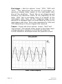
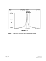
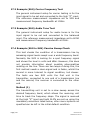
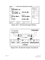
7.5 Oscilloscope Mode.
The oscilloscope is can be either single or dual trace and
has a sample rate of 5Msamples/s and a time base sweep
of 5µs/div to 5s/div, this provides the user with a
convenient tool for displaying and analyzing input
waveforms. (Sample display is shown in Fig 7.3)
This section provides the basic information necessary to
use the instrument. Use the „HI ∞‟ input as channel 1
(1MΩ ±300v pk) and „CH2‟ input (±10v pk 1MΩ) as
channel 2. Refer to section 3.4 “Instrument controls and
connections” for connector orientation.
Make sure the setting for channel 1 is „high Z‟ (channel 2
is fixed at 1MΩ) and confirm the CH1 setting before using
the oscilloscope. During operation using the UP/DOWN
arrow keys will increase or decrease the trigger level whist
the LEFT/RIGHT arrow keys will increase or decrease the
trace sweep time.
The oscilloscope has six functions available: „timebase‟,
„trigger level‟, „trigger mode‟, „trigger polarity‟, „pretrigger‟
and „traces‟. These are shown below in Fig 7.2 oscilloscope
setting screen.
Caution: Only use the „HI ∞‟ input and „CH2‟ input, being
aware that „CH2‟ input is only rated at ±10v pk. However,
the „HI ∞‟ input can be used up to ±300v pk.
Page | 29
Newtons4th Ltd
SLM3505 User Manual
OSCILLOSCOPE SETTINGS
Mode
timebase
trigger level
trigger mode
trigger polarity
pre trigger
traces
oscilloscope
200.0µs/div
+200.0mV
auto
rising edge
25%
single
Figure 7.2
Timebase - Sets the sweep rate of the oscilloscope, the
setting can be adjusted by following the “Keypad
Operation” instructions in section 4.1.
Trigger level – Sets the minimum voltage required to
start a sweep and can be adjusted by following the
“Keypad Operation” instructions in section 4.1.
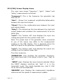
Trigger mode – Has three options: „auto‟, „normal‟ and
„single shot‟.
„Auto‟ puts the oscilloscope in the auto run mode where
the trace is synchronized to the trigger event. However, in
this mode it draws a trace even if no trigger event is seen.
„Normal‟: Sets the trace to respond to each trigger event.
If there are no trigger events the display is not updated
until a trigger event occurs.
„Single shot‟: Sets the trace to respond only to the first
trigger event captured. By pressing the “Home/Esc” key
re-arms the trigger circuit for the next event capture.
Trigger Polarity - Has two options: „rising edge‟ and
„falling edge‟. Selecting „rising edge‟ sets the oscilloscope
to start the sweep when the trigger voltage goes positive.
Selecting „falling edge‟, sets the oscilloscope to start the
sweep when the trigger voltage goes negative.
Page | 30
Newtons4th Ltd
SLM3505 User Manual
Pre-trigger – Has four options: „none‟, „25%‟, „50%‟ and
„75%‟. This determines the amount of pre-trigger, or
waveform display delay based on the mark/space ratio
time of the waveform. „None‟ has no pre-triggering and
therefore the waveform starts at the beginning of the
trace. „25%‟ has a pre-trigger time of a quarter of the
mark/space ratio time, so the triggering edge of the
waveform is displayed after the trace starts by 25% of the
mark/space ratio time. This is also applicable for 50% and
75% depending on the pre-trigger time required.
Traces – Traces has three options: „single‟, “dual” and
“ch2 current”. This selects either single or dual trace input
voltage operation. However in ch2 this will show the
current waveform developed across the generator shunt.
F
i
g
u
r
e
7
.
3
–
S
a
m
p
l
e
Page | 31
Dual Trace Display
Newtons4th Ltd
SLM3505 User Manual
8
SWEEP KEY– Sweep works in all modes. It allows the
instrument to sweep across a frequency band from the
start frequency to the end frequency in up to 2000 steps.
In VSWR mode, the sweep function only works with the
impedance method. The sweep setting menu screen is
shown below in Fig 8.1 displaying the 10 general
functions. However, additional functions will appear when
selecting some options from the right menu list.
*Note:
Make sure the generator is on before starting a
sweep.
SWEEP SETTINGS
display
sweep start
sweep end
sweep steps
sweep type
sweep type
peak hold
graph scaling
Frequency marker
search for peak
real time
30.0000kHz
500.000kHz
32
logarithmic
single
off
auto
off
off
start
Figure 8.1
Page | 32
Newtons4th Ltd
SLM3505 User Manual
8.1 Sweep Menu Functions
Display – Has three options: “real time”, “table” and
“graph”. Sweeping a band of frequencies stores each step
into a table. After the sweep is completed this information
may then be displayed as either a table or a graph
depending on the option selected. Selecting “real time”
returns the display back to normal operation.
This information may be saved via the „PROG‟ key either
internally, on a memory stick, or directly to a PC. Refer to
section 16 for saving information.
Sweep Start, Sweep End and Sweep Steps – The
“sweep start” and “sweep end” sets the two frequencies
over which the band will cover.
The “sweep steps” sets the amount of steps taken to
cover the frequency band, at each step a reading is taken
and is set depending on the accuracy and resolution
required. This can be a maximum of 2000, however the
more steps entered the more memory is required. The
frequencies and steps can be entered by following the
“Keypad Operation” instructions in section 4.1.
Linear Example of sweeping from 100 kHz to 200 kHz in 1
kHz steps:
Start by subtracting 100 kHz from 200 kHz. This gives the
difference of 100 kHz. Set the number of steps for 100
plus one or 101. Since the sweep starts at 100 kHz and
goes to 200 kHz, there are 101 – 1 kHz steps. Thus each
step is 1 kHz apart.
Sweep Type – Is displayed twice on the function menu
as there are two different options for each function. These
options are „linear/ logarithmic‟ and „single/continuous‟,
these are set depending on the type of sweep required.
The „continuous‟ option repeats the sweep until the
„HOME/ESC‟ key is pressed which stops the sweep.
Page | 33
Newtons4th Ltd
SLM3505 User Manual
Peak Hold – Has two options “on” and “off”. However, it
is only operational when the “continuous sweep” option is
selected. As the sweeps continue this allows the present
sweep readings to be compared against the previous
readings which then determines the highest level reached.
Graph Scaling – Has two options, “auto” and “manual”,
in most cases auto scaling will work and adjusts the graph
scale automatically to suite the measurement levels.
When a more specific graph scale is needed then the
“manual” option may be selected. This adds two
functions to the left menu, “graph maximum” and “graph
minimum”, here both levels can be specifically set by
following the “Keypad Operation” instructions in section
4.1.
Frequency Marker–Has three options “off”, “single” and
“dual”. If “single” is selected this adds “marker 1” function
to the left menu and If “dual” is selected this also adds
“marker 2” function to the left menu, allowing the setting
of a specific frequency to be entered. While in the sweep
mode it draws a vertical line on the graph at that
frequency
allowing
the
user
to
determine
the
measurement at that desired frequency. The frequency is
set by following the “Keypad Operation” instructions in
section 4.1.
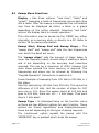
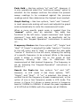
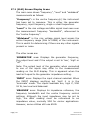
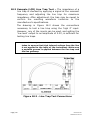
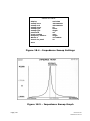
Search for Peak–Has two options “on” and “off”.
However, in LCR mode it has three options, “Off”,
“Single”, and “Dual”. If “on” is selected, this draws a
vertical line at the frequency of peak measurement, or the
option of one or two frequency peaks in LCR mode. The
screen in Figure 8.2 shows a sweep across a frequency
band of 150KHz to 250KHz. It shows the peak impedance
of 43.971kΩ at 200KHz with the marker set at 209KHz.
Page | 34
Newtons4th Ltd
SLM3505 User Manual
Figure 8.2
Start – The „start‟ function starts the sweep mode.
Page | 35
Newtons4th Ltd
SLM3505 User Manual
9
TUNE KEY – Has five functions: “centre frequency”, “step
type”, “frequency step”, “auto tune type” and “start auto
tune”. This selects the tuning method for the selective
level meter (SLM) and effectively tunes the instrument for
a particular frequency to look for. This is used with sweep
mode (graph display) where the instrument is looking
across a known frequency band for the expected signal.
Page | 36
Newtons4th Ltd
SLM3505 User Manual
9.1 Tune Menu Functions
Centre Frequency – Sets the frequency for which the
instrument input is looking for and is not the generator
frequency. This may be from line transmitter etc. This
frequency is set by following the “Keypad Operation”
instructions in section 4.1.
Step type – Sets the type of frequency step preferred
either linear or logarithmic.
Frequency Step – Sets the frequency step that is
increased or decreased when the LEFT/RIGHT arrows are
pressed. This frequency is set by following the “Keypad
Operation” instructions in section 4.1.
Auto Tune Type – This has two functions, “three stage
auto tune” and “single stage retune” and is normally used
with a (real time display). Three stage auto tune, is used
when the frequency is not known and effectively looks
across the sweep frequency range for the largest signal. It
then homes in on this signal and shows the frequency
obtained. “Single stage retune” will allow fine tuning
around the found frequency.
Start Auto Tune – This starts the auto tune function, the
real time display flashes “autotune” in the top left corner
whilst the tuning is taking place. When finished the found
frequency is displayed.
Page | 37
Newtons4th Ltd
SLM3505 User Manual
10
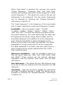
ZERO KEY – Displays information dependant on the mode
being used, (SLM/FRA) sets or clears the 0db level
reference. (LCR) sets or clears lead/cable compensation.
(VSWR) allows the storage of impedance measurements.
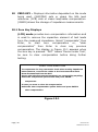
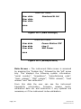
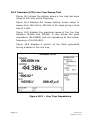
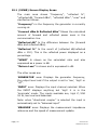
10.1 Zero Key Displays
(LCR) mode provides zero compensation information and
is used to remove the capacitive element of test leads
from the measured impedance. Select “compensate” then
Enter,
to
start
zero
compensation
or,
“clear
compensation” then Enter to clear any previous
compensation. The display in Figure 10.1 appears when
the zero key is pressed. “DUT” means „Device under Test‟,
be sure to clear compensation before doing further
testing.
ZERO COMPENSATION
To compensate for long connection leads when making impedance
measurements, connect the cables to the instrument but leave
them disconnected from the DUT.
Ensure that the disconnected terminals are not touching anything.
Select the compensate option below and press ENTER.
compensate
In case you want to clear the compensation
Select the clear compensation option below and press ENTER.
clear compensation
Figure 10.1
Page | 38
Newtons4th Ltd
SLM3505 User Manual
(FRA) mode provides 0dB reference and dB calculation
information. It is useful when looking for changes in gain
under specific conditions such as where an attenuator 3dB cut off point occurs in relation to the 0dB reference.
Select “set present measurement at 0dB reference” then
Enter, to start 0dB reference or, “clear 0dB reference”
then Enter to clear the setting. The screen in Figure 10.2
appears when the zero key is pressed.
0DB REFERENCE
The gain in dB is calculated from 20 log(ch2/ch1).
To look for changes in gain, it can be useful to define 0dB
under specific conditions.
set present measurement as 0dB reference
Clear the 0dB reference to display the absolute gain in dB
clear 0dB reference
Figure 10.2
Page | 39
Newtons4th Ltd
SLM3505 User Manual
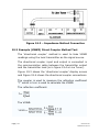
(VSWR) mode provides VSWR impedance measurement
and storage information. When a measurement is taken
using the generator it is then stored. The forward and
reflected power from a transmission line can then be
calculated and using the previously stored value. Select
“store impedance” then Enter, to store the measurement
or, “measure impedance” then Enter to return to real time
LCR mode. The screen in Figure 10.3 appears when the
zero key is pressed.
VSWR IMPEDANCE CONTROL
VSWR is calculated from the measurement impedance of the load.
The impedance has to be measured using the instrument generator.
The measured value can then be stored so that the forward and
Reflected power can be measured with the source connected.
Select the store impedance option below and press ENTER.
store impedance
To return to measuring the impedance, connect the generator.
Select the measure impedance option below and pres ENTER.
measure impedance
Figure 10.3
Page | 40
Newtons4th Ltd
SLM3505 User Manual
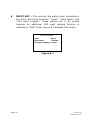
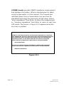
11
AUX KEY - This is for the Auxiliary Port Settings and is for
future applications, it is not functional at this time. The
screen in Figure 11.1 appears when the key is pressed
AUXILIARY PORT SETTINGS
This is reserved to control accessories connected to the
AUX port.
There are no accessories currently available.
Pres ESC to return to the measurements.
Figure 11.1
Page | 41
Newtons4th Ltd
SLM3505 User Manual
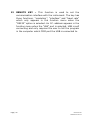
12
REMOTE KEY – This function is used to set the
communication interface with the instrument. The key has
three functions: “resolution”, “interface” and “baud rate”
which only appears in the function menu when the
“RS232” option is selected. An I.P. address appears in the
function menu when the “LAN” port is selected. USB is self
connecting and only requires the user to tell the program
in the computer which COM port the USB is connected to.
Page | 42
Newtons4th Ltd
SLM3505 User Manual
12.1 Remote Key Functions
Resolution – Has two options: “normal” and “high” this
alters the number of digits being displayed.
Interface - Has three options: “RS232”, “USB” and “LAN”
depending on the interface the user requires to connect
the instrument with.
Baud Rate – Only appears when RS232 interface is
selected and has four settings: 38400, 19200, 9600 and
1200 depending on the data rate of the system the
instrument is interfacing with.
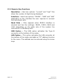
USB Option – The USB option activates the Type B
connector at the bottom of the meter.
LAN Option – This option activates the LAN connector at
the bottom of the meter and adds an “IP” address function
to the menu. The address can be entered using the arrow
keys.
Page | 43
Newtons4th Ltd
SLM3505 User Manual
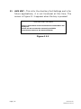
13
MONITOR KEY – This function is for future applications
and is not functional at this time. The screen in Figure
4.12 appears when this function is selected.
MONITOR SETTINGS
There are no monitor options presently available.
Press ESC to return to the measurements.
Figure 13.1
Page | 44
Newtons4th Ltd
SLM3505 User Manual
14
SYSTEM KEY – Has Nine functions: “initial settings”, “set
clock”, “set date”, “display”, “brightness”, “enlarge
results”, “phase convention”, ”keyboard beep” and “step
message”. These functions allow the user to configure the
instrument for individual requirements and also set
correct time and date for storage file records. When this
function is selected, pressing the RIGHT ARROW key
shows the user settings and the LEFT ARROW shows the
system data, both sets of information are explained later
in this section.
Page | 45
Newtons4th Ltd
SLM3505 User Manual
14.1 System Key Functions
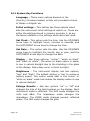
Language – These menu options depend on the
(Country) firmware loaded, ie Italy will provided a choice
of Italian or English etc.
Initial settings – This setting has three options which
sets the instrument initial settings at switch on. These are
either the settings stored in memory program 1, as per
the factory default or the settings which were last used.
Set Clock – This option sets the time. Use the UP/DOWN
arrow keys to highlight hours, minutes or seconds, and
the LEFT/RIGHT arrow keys to change the time.
Set Date – This option sets the date. Use the UP/DOWN
arrow keys to highlight the month, day or year, and the
LEFT/RIGHT arrow keys to change the date.
Display – Has three options: “colour”, “white on black”
and “black on white”. The white on black option is easier
to see in natural daylight due to the shielding in the glass
of the display. Glare does occur in direct sunlight.
Brightness – The instrument display has two options,
“low” and “high”. The default setting is „low‟ to conserve
battery power. This option works best in the „colour‟ or
„white on black‟ mode and makes the display easier to see
in natural daylight.
Enlarge Results – Has two options “on” or “off” and
changes the size of the text/numbers on the display. Each
instrument mode is different. The SLM mode changes the
volts and dBm. The impedance mode changes the
impedance. The VSWR mode changes percent reflected
power. The FRA mode changes the gain.
Page | 46
Newtons4th Ltd
SLM3505 User Manual
Phase Convention – This is available in both “LCR” and
“FRA” mode and displays the phase angle between the
input current and voltage. This phase angle has three
options: “-180° to +180°”, “0° to -360°” or “0° to +360°”
depending on user preference.
Keyboard Beep – An audible „beep‟ is available and
sounds every time a key is pressed. This option can be
“enabled”, or “disabled” if the sound is not required.
Step Message – Has two options “enabled” or “disabled”.
A single line message appears on the display in real time
mode when stepping the frequency or amplitude up or
down using the arrow keys. It shows the new value
selected. The „step message‟ may be disabled if desired.
User Settings – This function is accessed by pressing the
system key followed by the „right arrow‟ key, this will then
display the screen in figure 14.1. This allows the “user” to
enter three separate lines of information which is saved in
a data file when “save” is selected and ENTER pressed.
User Data, Example.
(Default 1st “Newtons4th Ltd”, can be overwritten).
Figure 14.2 is an example, which in this case shows the
station name, line number and technician name. The third
„user data‟ line (ie technician name), is the data displayed
on the „PROGRAM STORE/RECALL‟ display screen, See
section 16.
Page | 47
Newtons4th Ltd
SLM3505 User Manual
USER SETTINGS
User data
User data
User data
Newtons4th Ltd
save
Figure 14.1 (Main Settings)
USER SETTINGS
User data
User data
User data
Power Station XYZ
Line 2
Will Power
save
Figure 14.2 (example data)
Data Screen – The instrument Data screen is accessed
by pressing the “System Key” followed by the „left‟ arrow
key. This displays the following system information:
“serial number”, “impedance”, “manufacturing code”,
”main release”, “DSP release”, “FPGA release”, “boot
release” and “last calibration”.
From this data the user can see the instrument
traceability
information,
firmware
release
levels,
calibration date etc and determine if any updates are
necessary or if the instrument is due calibration.
Page | 48
Newtons4th Ltd
SLM3505 User Manual
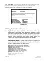
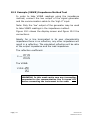
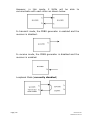
15 APP KEY – This function allows the main default setup of
the application option selected. Figure 15.1 shows what
appears when the “Inductance” option is selected.
APPLICATION SELECTION
Application
inductance
To configure the default options for this application select the
Initialize option below and press ENTER.
Initialize
Connect the low output to component and to low input.
Measurement
Output impedance
Generator frequency
Low output amplitude
series circuit
50Ω
1.00000KHz
1.0000Vrms
Figure 15.1
15.1 App Key Functions & menus
Application – Has a selection of normal, oscilloscope,
capacitance, inductance and resistance available. When
the option is selected and “Initialize” is entered this allows
the main default options menu of that application to
appear. Once selections have been made, press the
“Home” key and the appropriate display will appear.
Oscilloscope Menu – Setup options are as follows and
explanations for each setting can be found under the main
mode or measurement key description.
Input (high z, 50Ω 18W, low level, balanced)
Impedance (high impedance, 50Ω, 75Ω, 600Ω)
Timebase (enter time/div)
Trigger level (enter voltage level)
Trigger mode (auto, normal, single shot)
Trigger polarity (rising edge, falling edge)
Pretrigger (none, 25%, 50%, 75%)
Traces (single, dual, ch2 current)
Cursors (on, off)
Page | 49
Newtons4th Ltd
SLM3505 User Manual
Capacitance, Inductance & Resistance Menu – Setup
options are as follows and explanations for each setting
can be found under the main mode or measurement key
description.
Measurement (parallel circuit, series circuit)
Output impedance (50Ω, 75Ω, 600Ω)
Generator frequency (enter frequency Hz)
Low output amplitude (enter voltage level rms)
Page | 50
Newtons4th Ltd
SLM3505 User Manual
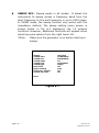
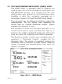
16
PROG KEY – Allows the user to internally or externally
store and recall instrument setups and readings. It has
the following functions: “memory”, “file type”, “action”,
“location”, “name” and “execute”.
The memory information in red at the bottom of the
screen displays, “memory status”, available files” and
“free space”. This applies to the internal or external
memory whichever is selected. They inform the user of
the memory status, how many files are available in
memory and how much memory space is still available.
All file directory information can be displayed by pressing
the “Prog” key and then the “SLM” button. This will allow
all the information to be displayed as a table and show
what the internal file directory contains. (By pressing the
“SLM” button again exits the directory).
Note: This information is also available to be read over
the instrument communication link.
Page | 51
Newtons4th Ltd
SLM3505 User Manual
16.1 Prog Key Functions
Memory – Memory has two options: ‘internal‟ and „USB
memory stick‟. The instrument has one gigabyte of
internal memory. Note: “USB Memory stick” appears in
blue if no device has been detected.
File type – Data has two options: „program‟ and „results‟.
Program allows the user to store a program setup that
may be used to provide a specific set of tests. Results
allow the user to store the results with their configuration
from a specific reading or sweep.
Action – Action has three options: “recall”, “store” and
“delete”. While previously selecting “program” or “results”
from the “data” function, the user must decide whether to
recall, store or delete the data. When storing, up to 999
setups/readings can be saved and each must have a
unique number. Memory location „0‟ is the „factory default‟
setting. The „delete‟ option allows the user to delete any
setup or reading.
Location & Name – These functions are used together.
Location must have a number but name is optional and
can remain as “empty”. Using the LEFT/RIGHT arrow keys
allows the location to be incremented or decremented. (0
= factory default). See menus and controls section and
figure 4.1 for entering alpha numeric characters.
Execute – Execute is used to control the „action‟ option.
After selecting an action (store, recall or delete), the
„execute‟ option is selected and the „enter‟ key pressed.
If the memory location selected already has results or a
setup stored, then the option: „select here and press
ENTER to overwrite‟, appears warning the user the
location ”number” already has data stored in it.
Page | 52
Newtons4th Ltd
SLM3505 User Manual
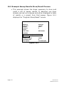
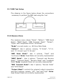
16.2 Example Sweep Results Store/Recall Process
This example shows the steps necessary to store and
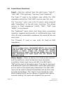
recall a set of sweep results. It assumes you have
already carried out a sweep and either displayed a table
of results or a graph from that sweep. Figure 16.1
displays the “Program Store/Recall” screen.
PROGRAM STORE/RECALL
Memory
File type
action
location
name
user data
Internal
results
store
3
Will Power
execute
select here and press ENTER to
overwrite
memory status
available files
free space
ready
2
1.073G Bytes
Figure 16.1
Page | 53
Newtons4th Ltd
SLM3505 User Manual
16.2 Storing Results
Press the “Prog” key
Displays the “Program Store/Recall” screen.
Memory:
Select “internal”.
File type:
Select “results”.
Location:
Using the Left/Right arrow keys increase or decrease
the number until an “empty” location is found.
Name:
Using the alpha numeric keys outlined in section 4.1
enter the appropriate name.
Action:
Select “Store” then Enter. This adds “user data” to
the function menu, using the alpha numeric keys
outlined in section 4.1 enter the appropriate
information. (This will appear as the 3rd line of user
data on the systems user settings screen).
Execute:
Select “execute” then Enter, data is now stored
Page | 54
Newtons4th Ltd
SLM3505 User Manual
16.3 Recalling Results
Press the “Prog” key
Displays the “Program Store/Recall” screen.
Memory:
Select “internal”.
File type:
Select “results”.
Location:
Using the Left/Right arrow keys increase or decrease
until the number required is found.
Name:
The correct name should be displayed.
Action:
Select “recall” then Enter.
Execute:
Select “execute” then Enter, which should now
display the results. In sweep mode selecting either
“graph” or “table” will have the results displayed in
the desired manner.
Page | 55
Newtons4th Ltd
SLM3505 User Manual
16.4 Deleting Results
Press the “Prog” key
Displays the “Program Store/Recall” screen.
Memory:
Select “internal”.
File type:
Select “results”.
Location:
Using the Left/Right arrow keys increase or decrease
until the number required is found.
Name:
The correct name should be displayed.
Action:
Select “delete” then Enter.
Execute:
Select “execute” then Enter, this should now display
the name “empty” for that location number.
Page | 56
Newtons4th Ltd
SLM3505 User Manual
16.4 Memory Status
(Displayed In Red) – “Memory status” monitors one of
two items. It lets the user know how much memory is
available either internally or on the USB memory stick.
The „available files‟ function lets the user know how many
data files are stored either internally or on the USB
memory stick.
Storing data to the memory stick creates two files. One
file extension is „.pcs‟ and is used by the software
interface provided by Newtons4th Ltd. The other file is a
comma delimited text file with the “.txt‟ extension. Full
information is provided in the appendix on this file format.
Page | 57
Newtons4th Ltd
SLM3505 User Manual
17
SELECTIVE LEVEL METER (SLM) MODE
The instrument is used when checking signal lines and is
designed to measure the level of individual frequencies
from 5 Hz to 5 MHz. The input signal is normally
connected to the high “Z” input or if terminated, the 50Ω
input. Figure 17.1 shows an example of the SLM mode
display.
Figure 17.1 – Selective Level Meter Display
Page | 58
Newtons4th Ltd
SLM3505 User Manual
17.1 (SLM) Screen Display Areas
The main area shows “frequency”, “level” and “wideband”
measurements as follows:
“Frequency”: is the centre frequency(s) the instrument
has been set to measure. This is either the generator
frequency, input frequency, single or dual frequencies.
“Level” is the rms voltage and dBm signal level seen over
the measurement frequency “bandwidth”, referenced to
the “centre frequency”.
“Wideband” is the rms voltage signal level across the
entire frequency range (5Hz to 5MHz) of the instrument.
This is useful for determining if there are any other signals
present or noise.
The other areas are:
„GENERATOR‟ area: Displays the generator frequency,
the output level and if the output is set to „low‟, „high‟ or
“off”.
Note: The output level of the generator when connected
to one of the inputs may differ to the measurement
reading on the SLM display. This is apparent when the
load isn‟t equal to the generator impedance setting.
„INPUT‟ area: Displays the input channel selected. When
the INPUT displays anything but „high‟ it is in the
„terminate‟ mode. The inputs available are, high Z, 50Ω
18 W, low level and balanced.
„MEASURE‟ area: Displays its impedance reference, the
frequency bandwidth and the centre frequency control
settings. Although the input impedance may be set to
high, the dBm reading must be referenced to an
impedance value, normally 50Ω for carrier applications.
However, some utilities still use 600Ω.
Page | 59
Newtons4th Ltd
SLM3505 User Manual
17.2 Example (SLM) Carrier Frequency Test
The general instrument setup for carrier testing is for the
input signal to be set and connected to the high “Z” input.
The reference measurement impedance set to 50Ω and
measurement frequency bandwidth at 100Hz.
17.3 Example (SLM) Audio Tone Test
The general instrument setup for audio tones is for the
input signal to be set and connected to the balanced
input. The reference measurement impedance set to 600Ω
and measurement frequency bandwidth at 25Hz.
17.4 Example (SLM to SLM) Passive Sweep Check
This test checks the condition of a transmission line by
assessing signal levels swept over a wide frequency band.
Normally the SLM is looking for a spot frequency signal
and shows the level in volts and dBm. However, this does
not provide information about possible abnormalities
residing on the line. There are two ways of doing this, the
first method needs a clean signal and is faster, whilst the
second is more tolerant to signal condition, but slower.
The tests use two SLM units the first unit is the
transmitter, connected to one end of a transmission line
and the second, the receiver is connected to the other
end.
Method (1)
The transmitting unit is set to a slow sweep across the
desired frequency band, which allows the receiving unit
time to track the frequency steps. The signal is received
at the high “Z” input and both SLM‟s are set up using the
mandatory selections listed below, other menu options not
specified can be left in the initial default condition.
Page | 60
Newtons4th Ltd
SLM3505 User Manual
Transmitter SLM set up:
Mode:
Output menu:
Measure menu:
Sweep menu:
FRA
Set generator amplitude (As applicable)
Set Waveform to “Sinewave”
Set generator to on “Low”
Set Speed to “Slow”
Set Start/Stop frequencies (eg 1KHz – 100KHz)
Set the number of steps
Set sweep to Log
Set sweep to “Continuous”
Start sweep
Receiver SLM set up:
Mode:
Input menu:
Measure menu:
Sweep menu:
SLM
Set to “High Z”
Set bandwidth to 100Hz
Set Centre frequency to “Input Frequency”
Set sweep to “Graph”
Set Start/Stop frequencies (As Tx unit)
Set the number of steps (As Tx unit)
Set sweep to Log
Set sweep to “Continuous”
Set Peak Hold to “on”
Set Graph Scaling to “Manual” (See Note 1)
Start sweep
Note 1: “Graph Scaling”, start with ±20dB, this should provide
a realistic starting range until an actual level is
determined from the detected signal.
Note 2: The transmitter SLM sweep can be started at any time.
However,
after
starting
the
receiver
sweep,
synchronization may take a little time to acquire until
the correct frequency is found.
Note 3: By pressing the Home/Esc button the SLM will then be
in its last sweep. However, if the receiver (only) button
is pressed it will continue to track the transmitter
frequency until the transmitter sweep is stopped, or
the receiver is turned off.
Page | 61
Newtons4th Ltd
SLM3505 User Manual
If an ideal transmission line is tested it should be similar
to the display in Fig 17.2.
For demonstration purposes a “CR” was inserted in the
transmission line to induce attenuation between 1KHz and
100KHz, the attenuated plot is displayed in Fig 17.3.
With a 2vpk output @ 1khz = 1.4v rms
With a 2vpk output @ 100kHz = 0.39v rms
Therefore gain = 20 x log(Vout/Vin) = -11dB
Figure 17.2 – Ideal Transmission Line
Page | 62
Newtons4th Ltd
SLM3505 User Manual
Figure 17.3 – Attenuated Transmission Line
Method (2)
The generating unit is set up the same as method 1.
However the receiving unit measure menu centre
frequency is set to “Single frequency”. Therefore as and
when the two sweep frequencies coincide the receiving
unit will plot the amplitude this method takes longer for
the whole plot to finish but is more tolerant of signal
condition.
Page | 63
Newtons4th Ltd
SLM3505 User Manual
18
IMPEDANCE METER (LCR) MODE
The meter is used to measure the impedance of different
circuits and can range from 100mΩ to 100kΩ. Typically
used in power line carrier applications, this could be a line
trap or parallel L/C in a line tuner etc. Figure 18.1 shows
an example of the LCR mode display.
The signal generator must be turned on to read
impedance. Note: when LCR mode is selected it
automatically turns the signal generator on.
For impedance measurements, normally the low output of
the signal generator is fed into the „high Z‟ input and the
circuit under test. Through the internal shunt the
instrument measures the current drawn from the signal
generator while the input measures the voltage across the
circuit being tested. When sweeping across a band the
instrument can detect up to two impedance peaks and
markers can be set for both.
From the fundamental components of voltage, (a + jb),
and those of the current, (c + jd), the complex impedance
is given by:
z =v/i
= (a + jb) / (c + jd)
Figure 18.1 – Impedance Meter Display
Page | 64
Newtons4th Ltd
SLM3505 User Manual
18.1 (LCR) Screen Display Areas
The main area shows “frequency”, “impedance”, “phase”
and “level” measurements as follows:
“Frequency”: is the frequency the generator is currently
running at.
“Impedance” is the value (Ω) measured as a ratio of the
voltage and phase angles.
“Phase” is the phase angle in degrees between the
voltage and current phases.
“Level” is the rms voltage and current levels measured.
The other areas are:
„GENERATOR‟ area: Displays the generator frequency,
the output level and if the output is set to „low‟, „high‟ or
“off”.
„INPUT‟ area: Displays the input channel selected. When
the INPUT displays anything but „high‟ it is in the
„terminate‟ mode. The inputs available are, high Z, 50Ω
18 W, low level and balanced.
„MEASURE‟ area: Displays the measurement impedance
reference and the speed of measurement update.
Note: When measuring impedance, keep the lead
between the generator output and the meter input
as short as possible. This limits the amount of error
caused by the capacitance of the coaxial lead. The
higher the frequency the more error is introduced
into the reading.
Page | 65
Newtons4th Ltd
SLM3505 User Manual
18.2 Example (LCR) Line Trap Test – The impedance of a
line trap is checked by applying a signal at the resonant
frequency and adjusting the line trap for maximum
impedance. After adjustment, the trap may be swept to
confirm the resulting waveform conforms to the
manufacturer‟s specifications.
The drawing in Figure 18.2 shows the connections
necessary to test a line trap using the „high Z‟ input.
However, any of the inputs can be used, and setting the
„low level‟ output to an amplitude of 2.0V, is sufficient for
testing line traps.
Note: When the trap is connected to the line, care must be
taken to ensure that high induced voltage from the line
is not applied to the input of the instrument. Make sure
a portable ground is applied between the line trap and
the line getaway.
Figure 18.2 - Line Trap Test Connections
Page | 66
Newtons4th Ltd
SLM3505 User Manual
18.3 Example (LCR) Line Trap Sweep Test
Figure 18.3 shows the display where a line trap has been
tuned to 200 kHz centre frequency.
Figure 18.4 displays the „sweep setting‟ screen setup to
sweep from 160 kHz to 250 kHz in 91 steps giving a step
size of 1 kHz.
Figure 18.5 displays the graphical sweep of the line trap
between 160kHz and 250kHz. It also shows the peak
impedance (45.206KΩ) and the impedance at the marker
frequency of (6.5014KΩ).
Figure 18.6 displays a portion of the table generated
during a sweep of the line trap.
Figure 18.3 – Line Trap Impedance
Page | 67
Newtons4th Ltd
SLM3505 User Manual
SWEEP SETTINGS
display
real time
sweep start
160.000kHz
sweep end
250.000kHz
sweep steps
91
sweep type
linear
sweep type
single
peak hold
off
graph scaling
auto
Frequency
Figuremarker
7.9 - Impedancesingle
Sweep Settings
Marker 1
211.00kHz
search for peak
on
start
Figure 18.4 – Impedance Sweep Settings
Figure 18.5 – Impedance Sweep Graph
Page | 68
Newtons4th Ltd
SLM3505 User Manual
F
i
g
u
r
e
1
8
.
6
Impedance Sweep Table
18.4 Example basic impedance (Capacitance) test setup
Figure 18.7 shows the setup for basic capacitance
measurement.
Measurement process setup
(1)
Press the “IMP” key to select impedance mode.
(2)
Select the “output” menu and set the frequency to
“1KHz” the low output is automatically selected in
this mode. (Other options leave as default settings).
(3)
Select the “input” menu and set the input to “low
level”. (Other options leave as default settings).
(4)
Select the measure menu and set the measurement
to “parallel circuit” (Other options leave as default
settings).
(5)
Connect the instrument and DUT capacitor as per Fig
18.7 below then revert to the main display where it
will show the measured capacitance.
Page | 69
Newtons4th Ltd
SLM3505 User Manual
NOTE: The instrument here is shown upside down
Fig 18.7
Page | 70
Newtons4th Ltd
SLM3505 User Manual
19
VOLTAGE STANDING WAVE RATIO (VSWR) MODE
The VSWR Meter is generally used to measure the
standing wave ratio of a communications transmission line
and associated circuitry. It is derived from the max
standing wave value against the min standing wave value,
therefore a ratio, but commonly expressed as a
percentage. Figure 19.1 shows the VSWR mode display.
The instrument uses two different methods to make these
measurements. The first method uses impedance the
second uses an external directional coupler, (Option
available from Newtons 4th Ltd).
The impedance method uses the signal generator as the
current source and an input, (normally the “high z), to
measure the voltage developed across the load. From
these two values the impedance and VSWR is calculated.
The directional coupler method uses a separate piece of
equipment a “Directional Coupler”, plugged into the
balanced inputs. The coupler is connected between the
transmitter and its load and provides directly measured
values of forward and reflected power from which the
VSWR is calculated.
Figure 19.1 – VSWR Mode
Page | 71
Newtons4th Ltd
SLM3505 User Manual
19.1 (VSWR) Screen Display Areas
The main area shows “frequency”, “reflected %”,
“reflected dB, “forward dBm”, “reflected dBm”, “vswr” and
clarified as follows.
“Frequency”: is the frequency the generator is currently
running at.
“Forward dBm & Reflected dBm” Shows the calculated
amount of forward and reflected power seen in the
communication line.
“Reflected dB” Is the difference between the (forward
dBm and reflected dBm).
“Reflected %” Is the result of (reflected dB/reflected
dBm x 100). This is the reflected power displayed as a
percentage.
“VSWR” Is shown as the calculated ratio and also
expressed as a power in dB.
“Return Loss” Is shown and is expressed in dB.
The other areas are:
„GENERATOR‟ area: Displays the generator frequency,
the output level and if the output is set to „low‟, „high‟ or
“off”.
„INPUT‟ area: Displays the input channel selected. When
the INPUT displays anything but „high‟ it is in the
„terminate‟ mode. The inputs available are, high Z, 50Ω
18 W, low level and balanced.
Note: when “directional coupler” is selected the input is
automatically set to “balanced input”
„MEASURE‟ area: Displays the measurement impedance
reference and the speed of measurement update.
Page | 72
Newtons4th Ltd
SLM3505 User Manual
19.2 Example (VSWR) Impedance Method Test
In order to take VSWR readings using the impedance
method, connect the low output of the signal generator
and the communication cable to the „high Z‟ input.
Note: Only the „low‟ output of the generator may be used
to take VSWR readings in the impedance method.
Figure 19.1 shows the display screen and figure 19.2 the
connections.
Ideally for a line terminated in its own characteristic
impedance there is no reflection, any other impedance will
result in a reflection. The calculated reflection will be ratio
of the output impedance and the load impedance.
The reflection coefficient:
Γv
The VSWR:
VSWR =
WARNING: In this mode make sure any transmitter
connected to the communication line is turned OFF
before connecting the instrument to the cable.
Page | 73
Newtons4th Ltd
SLM3505 User Manual
Figure 19.2 – Impedance Method Connection
19.3 Example (VSWR) Direct Coupler Method Test
The „directional coupler‟ method is used to take VSWR
readings using the local transmitter as the signal source.
The directional coupler input and output is connected in
the communication cable between the transmitter output
and the transmitter load (ie in figure 19.4 a Line Tuner).
Figure 19.3 shows the „directional coupler‟ display screen
and Figure 19.4 shows the directional coupler connections.
The coupler is used to measure the reflection coefficient
“Γ” which in turn is used to calculate the VSWR.
The reflection coefficient:
Γ
The VSWR:
VSWR
Page | 74
=
=
Newtons4th Ltd
SLM3505 User Manual
Figure 19.3 – Directional Coupler Method
Figure 19.4 - Directional Coupler Connections
Page | 75
Newtons4th Ltd
SLM3505 User Manual
19.4 Example (VSWR) Sweep Test
The sweep function can be enabled in the „VSWR
impedance‟ mode. The load or (line tuner) may be swept
to determine the frequency it is tuned to and the
bandwidth. This information can be used to confirm that
the VSWR figures comply with the system specification
over the swept frequency band.
Note: The sweep function only works in the „impedance‟
mode.
Page | 76
Newtons4th Ltd
SLM3505 User Manual
20
FREQUENCY RESPONSE ANALYSER (FRA) MODE
The Frequency Response Analyzer (FRA) has a frequency
range of 5Hz to 5MHz and is used to measure the dynamic
response of a system or piece of equipment.
A sine wave is applied to the system under test and the
resulting output response is measured.
Figure 20.1 shows the Frequency Response Analyzer
display screen.
Figure 20.1 – Frequency Response Analyzer
Page | 77
Newtons4th Ltd
SLM3505 User Manual
20.1 (FRA) Screen Display Areas
The main area shows “frequency”, “gain”, “phase” and
“delay” measurements as follows:
“Frequency”: This is the frequency the generator has
been set to.
“Gain”: Shows the measured amplification/attenuation
between the input and output.
“Phase”: This is the relationship seen between the input
and output phases.
“Delay”: This determines the time between the input and
output phases and considers this measurement to be the
delay time.
“Level”: The “bottom left” level displays the input rms
voltage being fed into the system under test.
Note: The output level of the generator when connected
to one of the inputs may differ to the measurement
reading on the FRA display. This is apparent when the
load isn‟t equal to the generator impedance setting.
“Level”: The “bottom right” level displays the output rms
voltage from the system under test.
The other areas are:
„GENERATOR‟ area: Displays the generator frequency,
the output level and if the output is set to „low‟, „high‟ or
“off”.
„INPUT‟ area: Displays the input channel selected. When
the INPUT displays anything but „high‟ it is in the
„terminate‟ mode. The inputs available are, high Z, 50Ω
18 W, low level and balanced.
„MEASURE‟ area: Displays the measurement impedance
reference and the speed of measurement update.
Page | 78
Newtons4th Ltd
SLM3505 User Manual
20.2 Example (FRA) Test
To apply a frequency response/phase gain test to a piece
of equipment the normally “low” generator output is
connected to the “High z” input of the instrument and to
the input of the system under test.
The system under test output is then applied to the
instrument “CH2”. Measurements are then displayed
showing the gain, phase etc seen between the two
waveforms.
Caution: Do not use the „balanced input‟ in FRA applications.
Only use the „HI ∞‟ input and „CH2‟ input, being aware that
„CH2‟ input is only rated at ±10v pk. However the „HI ∞’
input can be used up to ±300v pk.
(FRA) Sweep
A sweep can be set up to measure a dynamic frequency or
phase/gain system response over a chosen frequency
bandwidth.
This is instigated using the sweep function and can be
displayed as a table or graph to show the system
characteristics over the frequency band.
The DFT technique can measure phase as well as
magnitude and is inherently good at rejecting noise. By
computing the gain and phase at a number of points over
a frequency range gives results that show a graph on the
display.
Page | 79
Newtons4th Ltd
SLM3505 User Manual
The DFT analysis yields two components – in-phase and
quadrature, or „a‟ and „b‟ values – from which the
magnitude and phase can be derived. The fundamental inphase and quadrature values of a periodic waveform, v( ),
are given by:
a1
b1
For a sampled signal, the formulae become:
a1
b1
Where n is the number of samples for an integral number
of complete cycles of the input waveform, and c is the
number of cycles.
Having computed the real and quadrature components,
the magnitude and phase of each channel can be derived:
mag = (a12 + b12)
= tan-1(b1/a1)
The relative gain and phase of the circuitry under test at
that particular frequency is derived from the real and
quadrature components by vector division:
vector gain = (a + jb) {ch2} / (a + jb) {ch1}
gain = magnitude (vector gain)
phase = tan-1(b/a (vector gain))
The gain is usually quoted in dB:
dB
Page | 80
= 20 log10(gain)
Newtons4th Ltd
SLM3505 User Manual
21.1 Bit Error Rate
The Bit Error Rate (BER) functionality of the SLM3505
allows diagnosis of signal problems in the field. Bit Error
Rate is the ratio between the number of bit errors
transmitted and the number of bits received.
BER = Number of Error Bits / Number of Bits Transmitted
The Bit Error Rate test involves sending a Pseudo-Random
Binary Sequence (PRBS), a sequence of binary 1‟s of 0‟s
which exhibits certain randomness and autocorrelation
properties. The PRBS bit sequence is used in testing
transmission lines equipment because of their randomness
properties.
When BER mode is enabled, the system expects to receive
the same pattern that it‟s transmitting. The total number
of bits transmitted, error bits and the BER (%) is
displayed on the screen.
The Bit Error Rate tester consists of two Modules:
a) PRBS Generator
b) PRBS Receiver
Page | 81
Newtons4th Ltd
SLM3505 User Manual
21.2 Theory of Operation
The Bit Error Rate test involves sending a Pseudo-Random
Binary Sequence (PRBS). A Pseudo-Random binary
sequence is a periodic, deterministic signal with properties
similar to white noise. A PRBS is like a long recurring
decimal number – it looks random if you look at a short
piece of the sequence, but it actually repeats itself every
m bits (see section 1.3).
The PRBS signal is generated using a shift register and an
XOR gate.
The Bit Error Rate Module consists of 2 modules:
a) PRBS generator: The PRBS bit-patterns are generated
in a linear feedback shift register. The user has the
ability to select the required bit pattern sequence (see
section 1.3) for different bit patterns. Each bit pattern
sequence will have a PRBS shift register length (X)
which will be described in section 1.3.
b) PRBS Receiver: The receiver has signaling output for
synchronization state, synchronization loss and bit
errors.
The receiver is synchronized when 2*X (X=PRBS shift
register length) error free bits are received. The
receiver will begin counting the number of bytes
received when the receiver is synchronized and will
continue counting even when the receiver loses sync.
The receiver loses synchronization when the error rate
over the last 128 bits exceeds 20%. To detect this
level, the bit errors during the last 128 received bits are
memorized. If there are more than 25 errors within
these 128 bits, the receiver loses sync.
The number of error bit is incremented when a bit error
in the received bit sequence is detected.
Page | 82
Newtons4th Ltd
SLM3505 User Manual
21.3 PRBS Test Patterns
The Pseudo-Random test patterns generated by the
SLM3505 conform to the ITU-T standards O.150, O.151,
O.152 and O.153. The tabel below describes the test
patterns supported by the SLM3505.
PRBS
Type
2^9 – 1
2^11 - 1
2^15-1
2^20-1
PRBS
Shift
No OF
Reg
Bits (m)
Length
(X)
9
11
15
20
Standard
Suggested
Data Rate
(Kbps)
512
ITU-T
O.150/O.153
Upto 14.4
2047
ITU-T
O.150/O.152
/O.153
64, n*64
(n=1..31)
32767
1544, 2048,
ITU-T
6312, 8448,
32064,
O.150/O.151
44736
ITU-T
1048575
O.150/O.151
1544, 6312,
32064,
44736
Table 1: PRBS Patterns
Page | 83
Newtons4th Ltd
SLM3505 User Manual
21.4 BER Send Mode
2 Modes, namely, “Fixed” and “Continuous”. Fixed mode
involves sending a fixed number of bits. This mode is not
currently implemented. Only continuous mode is enabled.
21.5 BER Transmit Mode
The BER module currently supports 2 types of line codes,
namely, “normal” and “G703” mode.
G703 Mode (64kb/s codirectional interface): In this mode,
the 64kb/s period is divided into four unit intervals. A
binary 1 is coded as a block of “1100” and a binary 0 is
coded as a block of “1010”. The binary signal is converted
into a 3-level signal by alternating the polarity of
consecutive blocks. The alternation in polarity of blocks is
violated every 8th bit. The current release represents a
binary 1 with a +/- 1V and a 0 with 0V. The nominal bit
rate is 256 Kb/s with a test load impedance of 120 ohms.
21.6 BER Test Mode
The BER module has 4 test modes namely “Transmit and
Receive”, “Transmit”, “Receive” and “Loopback Mode”.
In transmit and receive mode, the PRBS generator and
the receiver is enabled.
Page | 84
Newtons4th Ltd
SLM3505 User Manual
However, in this mode, 2 SLMs will be
communicate with each other as shown below.
able
to
In transmit mode, the PRBS generator is enabled and the
receiver is disabled.
In receive mode, the PRBS generator is disabled and the
receiver is enabled.
Loopback Mode (currently disabled)
Page | 85
Newtons4th Ltd
SLM3505 User Manual
21.7 BER Test Setup
The drawing in the figure below shows the connections
necessary to perform the BER test using the „low‟.
21.8 Measure Menu
The measure menu shows “Mode”, “Pattern”, “BER Send
Mode”, “BERT Mode”, “BER Transmit Mode”, “Output”,
“Input” and “Amplitude Control” as follows:
“Mode”: current mode, i.e., Bit Error Rate Mode
“Pattern”: Has 4 options, namely, “2^9-bits”, “2^11bits”,”2^15-bits” and “2^20-bits”
“BER Send Mode”: Has 2 options, “fixed” and
“continuous” Note: Fixed Mode not currently implemented
“BERT Mode”: Has 4 options, “Transmit and Receive
Mode”, “Transmit Mode”, “Receive Mode” and “Loopback
Mode” Note: Loopback Mode not currently implemented
“BER Transmit Mode”: Has 2 options, “Normal Mode”
and “G703 Mode”
“Output Mode”: controls the relevant output connection
and has 3 options, namely, “off”, “low” and “high”. Note:
High Output Mode not currently implemented
Page | 86
Newtons4th Ltd
SLM3505 User Manual
21.9
(BER) Screen Display Area
The main area shows “Total Bits Transmitted”, “No of
Error Bits”, “Total Bits Received”, “BER (%)”, “BER (Last
128 bits)” and “Synchronized / No Sync” as follows:
“Total Bits Transmitted”: is the total number of bits
transmitted by the SLM3505
“No. Of Error Bits”: Shows the number of bit errors
detected
“Total Bits Received”: Shows the total number of bit
received
“BER %”: Shows the bit errors that were detected versus
the total number of test bits received since the test
started
“BER (Last 128 Bits)”: The screen shows “less than 0.2”
if the error rate exceeds 20% in the last 128 bits. If there
are more than 25 errors within the last 128 bits, then the
BER shows less than 0.2.
If the error rate is less than 20% in the last 128 bits, the
screen will “show greater than 0.2”
“Synchronized / No Sync”: The screen shows “No
Sync” if the error rate exceeds 20% in the last 128 bits. If
there are more than 25 errors within the last 128 bits,
then the BER shows less than 0.2.
If the error rate is less than 20% in the last 128 bits, the
screen will “Synchronized”.
The “Synchronized / No Sync” indicator is large and easy
for inspectors to read.
21.10 (BER) Keypad Operation
Press the HOME/ESC key at any time to abort the present
activity and restart the BER test
Page | 87
Newtons4th Ltd
SLM3505 User Manual
22
Technical Specification
SELECTIVE LEVEL METER
Frequency Range
Frequency Accuracy
Magnitude Accuracy
Inputs (Unbalanced) Type & Connection
Pass Bandwidth Frequency Range Settings
Frequency Setting
Frequency Acquisition
Level Meter Accuracy
Frequency Synchronization
Selectivity
Pass bandwidth (@a ≤ 0.5dB)
Pass bandwidth (@a = 3dB)
Stop Band Attenuation (@a ≥ 30dB)
Stop Band Attenuation (@a ≥ 60dB)
High Voltage Input
Max Input
Input Impedance
50Ω Input
Max Input
Input Impedance
Low Level Input
Max Input
Input Impedance
Input (Balanced)
Max Input
Input Impedance
Input Type
Input Connection
Second Input
Channel 2 (CH2)
Page | 88
5HZ to 5MHz
±0.03% over all temperature range
<1KHz: 0.05% mg + 0.05% rdg + 50uV
<10KHz: 0.05%mg + 0.05% rdg + 0.01%/KHz + 50uV
<5MHz: 0.05%mg + 0.25% rdg + 0.001%KHz + 50uV
Differentially isolated & Isolated BNC
1Hz, 3Hz, 25Hz, 100Hz, 1.95K, 3.1K, (Wide)
All frequencies to 6 digit resolution
Single and 3 stage frequency acquisition
±0.01dB
Auto Sync between meter and generator
Narrow
25Hz
Wide
3.1KHz
±4Hz
±480Hz
= 12Hz
= 1.5KHz
±240Hz
±6KHz
±300v Peak
1MΩ ±5% // 30pf
18W (30v rms)
50Ω ±1% // 30pf
±10v Peak
50Ω ±1% // 30pf
75Ω ±1% // 30pf
600Ω ±1% // 30pf
1MΩ ±5% // 30pf
±10v Peak
50Ω ±1% // 30pf
75Ω ±1% // 30pf
600Ω ±1% // 30pf
1MΩ ±5% // 30pf
Differential
3 x 4mm Connectors – Positive, Negative & Gnd
±10v Peak 1MΩ ±5% // 30pf
Newtons4th Ltd
SLM3505 User Manual
SIGNAL GENERATOR
Generator Type
Generator Waveforms
Frequency Accuracy
Magnitude Accuracy
High Level Output
Frequency range
Output Level
Output Impedance
Direct Digital Synthesis (DDS), Single Frequency
or sweep
Sinewave, Square, Triangle, White Noise
±5ppm over all temperature range (6 digit
resolution)
±1% ±1%/MHz (4 digit resolution)
10KHz to 5MHz
2W into 50Ω (10v rms)
50Ω ±2%
75Ω ±2% (Option)
Low Level Output
Frequency range
5Hz to 5MHz
Output Level
5Vrms into high impedance
Output Impedance
50Ω ± 2% max +24dBm
75Ω ± 2% max +22dBm
600Ω ± 2% max +15dBm
0 to 1s (1ms steps)
Frequency shift delay timer
IMPEDANCE ANALYZER
Impedance Range
Accuracy
Frequency Range
Features
100mΩ to 100KΩ
<10KHz: 1%rdg
<1MHz: 1%rdg + 0.005%/KHz + 50uV
<5MHz: 5%rdg + 0.002%/KHz + 50uV
5Hz to 5MHz
LCR Measurements (Inductance, Capacitance,
Resistance, Tan delta QF).
Lead compensation (Zero lead function).
Impedance versus frequency curve.
OSCILLOSCOPE
Sample Rate
Timebase
Trigger
Pretrigger
Input Ranges
Second Input (CH2)
Page | 89
5 Msamples/S
5µs/div to 5s/div
Auto, Normal, or Single shot
None, 25%, 50%, 75%
As Selective level Meter
±10v Peak 1MΩ ±5% // 30pf
Newtons4th Ltd
SLM3505 User Manual
VSWR METER
Accuracy
Features
1% of reading from 5Hz up to 1MHz
5% of reading above 1MHz to 5MHz for
power measurements (forward & reflected)
at VSWR=3
Forward Power
Reflected Power
% Reflected Power
Frequency under test visible on one screen
FREQUENCY RESPONSE ANALYSER
Frequency Range
Gain Accuracy dB
Phase Accuracy°
5Hz to 5MHz
0.02dB < 1KHz
0.05dB < 10KHz
0.1dB + 0.001dB/KHz
0.02° < 10KHz
0.02° + 0.003°/KHz
GENERAL SPECIFICATIONS
Sweep Steps
Set-up and Data Storage
Interface
Real Time Clock
Data Storage
Display and Resolution
Power Source
Battery Type and capacity
Temperature Range
Page | 90
Up to 2000 steps in all sweep functions
Up to 1000 analyzer setups, readings and sweep
results can be stored.
USB, RS232, LAN
Time and date stamp for data stores
Internal 1Gb flash, external USB pen port
⅟4 VGA Colour, 6 digit frequency, 5 digit voltage,
4 digit dBm
9 – 18v @ 3A AC adapter or 12v dc from vehicle
or external batteries
3 x Lithium polymer (up to approx 2 hours)
-5°C to +50°C
Newtons4th Ltd
SLM3505 User Manual
23. Appendix A – Text File Format
Saving test results generates two files. The file name is
represented by the number location chosen (1-999) from
the „PROGRAM STORE/RECALL‟ menu. For example, if the
file location chosen is: 11, the files generated would be
PCA_R011.pcs and PCA_R011.txt.Each file has the same
name but different extensions. The first file with the .pcs
extension name is the file that the instrument uses to
display the test results when that file is recalled.
The second file is a comma delimited text file (CSV) and
may be viewed using any text editing/viewing program.
The text file has two parts, the header section and the
data/results section. The header includes the status of the
instrument at the time the test results were taken. This
information includes all three USER data inputs from the
„USER SETTINGS‟ menu, the file name, time and date
stamp, serial number, last calibration date and other
pertinent information.
The data may be imported into Excel or other programs
that can access comma delimited files. Section 21.1 is the
header information from a sample impedance sweep file.
The information in the header is explained in the „Header
Format‟ following the example file.
Note: The header information varies based on the setup
of the instrument.
Page | 91
Newtons4th Ltd
SLM3505 User Manual
24.1 Example Text File
NEWTONS4TH LTD
Instrument,type,SLM3505
,serial number,1216
,firmware version,2.13
,calibration,10_DEC_2008_1029_SBC
User ID
,user name 1,PowerComm Solutions
,user name 2,
,user name 3,John Doe
Record,file name,PCA_R011.TXT
,name,Test
,datestamp (mmddyyyy),05262009
,timestamp,1132
measurement settings,mode,impedance meter
,measurement,impedance magnitude
,speed,medium
,filter,normal
generator settings,amplitude control,V
,low output amplitude, 2.0000E+00,Vrms
,amplitude step, 1.1000E+00
,fsk control,disabled
,generator frequency, 5.0000E+04,Hz
,frequency step, 1.0000E+02,Hz
,waveform,sinewave
,output,low
,output impedance,50 Ohms
input settings,input,high Z
,scale factor, 1.0000E+00
,CH1 input ranging,full autorange
sweep settings,display,graph
,sweep start, 3.0000E+04,Hz
,sweep end, 5.0000E+05,Hz
,sweep steps,32
,sweep type,linear
,sweep type,single
,graph scaling,auto
,marker,off
,search for peak,off
Page | 92
Newtons4th Ltd
SLM3505 User Manual
24.2 Text File Header Format Explanation
1. The first line „NEWTONS4TH LTD‟ is the name of the
company that manufactures the instrument and is
embedded in the firmware.
2. Lines two to five are the serial number of the
instrument, manufacturing code, firmware release
versions and date of last calibration. This information is
accessed by pressing the „SYSTEM‟ key and the „LEFT
ARROW‟ key.
3. Lines six to nine are the „user data‟ area. This
information is accessed by pressing the „SYSTEM‟ key
and the „RIGHT ARROW‟ key.
4. Lines ten to thirteen are from the „PROGRAM
STORE/RECALL‟ menu. These lines provide the number
(000 to 999) of the file (location), the name of the file
and the date and time stamp that was provided at the
time the data was saved in the instrument.
5. Lines 14 to 17 are from the „MEASUREMENT SETTINGS‟
menu. These lines provide the mode the instrument
was in when the data was acquired, how the
measurement was taken and the speed and filter
settings.
6. Lines 18 to 26 are the „GENERATOR SETTINGS‟. These
lines provide the settings of the generator at the time
the data was acquired.
7. Lines 27 to 29 are the „INPUT SETTINGS‟. These lines
provide the input settings at the time the data was
acquired.
8. Lines 30 to 38 are the „‟SWEEP SETTINGS‟. These lines
provide the input settings at the time the data was
acquired.
Page | 93
Newtons4th Ltd
SLM3505 User Manual
24.3 Text File Example Sweep Data
The data portion of the file starts at „Results, sweep data‟.
This example is an impedance sweep. There are five
columns of data: Frequency (Hz), Impedance (Ohms),
Phase (degrees), Resistance (Ohms) and Reactance
(Ohms).
The two columns Frequency and Impedance may be used
in Excel to plot a frequency versus impedance graph. All
information is given in scientific notation.
In this example the frequency starts at 150 kHz and goes
to 210 kHz. The impedance starts at 252 ohms and goes
to a peak impedance of 6700 ohms and then down to 235
ohms. Note: the the headers and columns do not line up.
Results,sweep data
Frequency(Hz),Impedance(Ohm),Phase(deg),Resistance(Ohm),Reactance (Ohm)
1.5000E+05, 2.5299E+02, 8.9272E+01, 1.9924E+04, 2.5301E+02
1.5122E+05, 2.6595E+02, 8.9195E+01, 1.8921E+04, 2.6597E+02
1.5245E+05, 2.8018E+02, 8.9104E+01, 1.7916E+04, 2.8021E+02
1.5367E+05, 2.9589E+02, 8.8996E+01, 1.6897E+04, 2.9594E+02
1.5490E+05, 3.1331E+02, 8.8875E+01, 1.5960E+04, 3.1337E+02
1.5612E+05, 3.3274E+02, 8.8739E+01, 1.5113E+04, 3.3282E+02
1.5735E+05, 3.5461E+02, 8.8583E+01, 1.4334E+04, 3.5471E+02
1.5857E+05, 3.7929E+02, 8.8400E+01, 1.3579E+04, 3.7944E+02
1.5980E+05, 4.0746E+02, 8.8190E+01, 1.2898E+04, 4.0767E+02
1.6102E+05, 4.4011E+02, 8.7904E+01, 1.2031E+04, 4.4040E+02
1.6225E+05, 4.7794E+02, 8.7612E+01, 1.1468E+04, 4.7835E+02
1.6347E+05, 5.2246E+02, 8.7259E+01, 1.0924E+04, 5.2306E+02
1.6469E+05, 5.7575E+02, 8.6835E+01, 1.0430E+04, 5.7663E+02
1.6592E+05, 6.4062E+02, 8.6313E+01, 9.9621E+03, 6.4195E+02
1.6714E+05, 7.2129E+02, 8.5656E+01, 9.5223E+03, 7.2337E+02
1.6837E+05, 8.2443E+02, 8.4810E+01, 9.1143E+03, 8.2782E+02
1.6959E+05, 9.6025E+02, 8.3673E+01, 8.7134E+03, 9.6614E+02
1.7082E+05, 1.1480E+03, 8.2109E+01, 8.3617E+03, 1.1589E+03
1.7204E+05, 1.4224E+03, 7.9769E+01, 8.0082E+03, 1.4454E+03
1.7327E+05, 1.8611E+03, 7.5908E+01, 7.6439E+03, 1.9189E+03
1.7449E+05, 2.6516E+03, 6.8864E+01, 7.3535E+03, 2.8428E+03
1.7571E+05, 4.3198E+03, 5.2361E+01, 7.0735E+03, 5.4552E+03
1.7694E+05, 6.7700E+03, 6.1537E+00, 6.8092E+03, 6.3152E+04
1.7816E+05, 4.6626E+03,-4.4704E+01, 6.5601E+03,-6.6282E+03
1.7939E+05, 2.8250E+03,-6.3450E+01, 6.3203E+03,-3.1581E+03
1.8061E+05, 1.9707E+03,-7.1084E+01, 6.0789E+03,-2.0832E+03
1.8184E+05, 1.5017E+03,-7.5157E+01, 5.8618E+03,-1.5535E+03
1.8306E+05, 1.2105E+03,-7.7630E+01, 5.6503E+03,-1.2393E+03
1.8429E+05, 1.0138E+03,-7.9289E+01, 5.4552E+03,-1.0318E+03
1.8551E+05, 8.7227E+02,-8.0463E+01, 5.2643E+03,-8.8450E+02
1.8674E+05, 7.6550E+02,-8.1345E+01, 5.0871E+03,-7.7432E+02
1.8796E+05, 6.8228E+02,-8.2022E+01, 4.9162E+03,-6.8895E+02
Page | 94
Newtons4th Ltd
SLM3505 User Manual
1.8918E+05,
1.9041E+05,
1.9163E+05,
1.9286E+05,
1.9408E+05,
1.9531E+05,
1.9653E+05,
1.9776E+05,
1.9898E+05,
2.0020E+05,
2.0143E+05,
2.0265E+05,
2.0388E+05,
2.0510E+05,
2.0633E+05,
2.0755E+05,
2.0878E+05,
2.1000E+05,
Page | 95
6.1556E+02,-8.2563E+01,
5.6086E+02,-8.3000E+01,
5.1521E+02,-8.3355E+01,
4.7641E+02,-8.3605E+01,
4.4332E+02,-8.3859E+01,
4.1459E+02,-8.4073E+01,
3.8945E+02,-8.4259E+01,
3.6727E+02,-8.4421E+01,
3.4753E+02,-8.4561E+01,
3.2988E+02,-8.4684E+01,
3.1396E+02,-8.4787E+01,
2.9957E+02,-8.4880E+01,
2.8649E+02,-8.4962E+01,
2.7451E+02,-8.5035E+01,
2.6356E+02,-8.5098E+01,
2.5345E+02,-8.5156E+01,
2.4412E+02,-8.5210E+01,
2.3547E+02,-8.5255E+01,
4.7553E+03,-6.2078E+02
4.6022E+03,-5.6507E+02
4.4521E+03,-5.1870E+02
4.2773E+03,-4.7939E+02
4.1438E+03,-4.4587E+02
4.0149E+03,-4.1682E+02
3.8935E+03,-3.9142E+02
3.7777E+03,-3.6902E+02
3.6662E+03,-3.4910E+02
3.5609E+03,-3.3131E+02
3.4556E+03,-3.1526E+02
3.3566E+03,-3.0077E+02
3.2622E+03,-2.8760E+02
3.1716E+03,-2.7555E+02
3.0842E+03,-2.6452E+02
3.0014E+03,-2.5436E+02
2.9231E+03,-2.4497E+02
2.8464E+03,-2.3628E+02
Newtons4th Ltd
SLM3505 User Manual
25. Appendix B – Contact Details
Please direct all queries or comments regarding the KinetiQ
instrument or manual to:
Newtons4th Ltd.
30 Loughborough Rd.
Mountsorrel
LOUGHBOROUGH
LE12 7AT
United Kingdom
Tel: (0116) 230 1066
international
+44 116 230 1066
Fax: (0116) 230 1061
international
+44 116 230 1061
E-mail address: [email protected]
[email protected]
web site: www.newtons4th.com
At Newtons4th Ltd. we have a policy of continuous product
improvement and are always keen to hear comments, whether
favourable or unfavourable, from users of our products.
An example comment form can be found at the end of this manual
– if you have any comments or observations on the product please
fill a copy of this form with as much detail as possible then fax or
post it to us.
Alternatively send an e-mail with your comments.
Page | 96
Newtons4th Ltd
SLM3505 User Manual
SLM3505 comments
serial
number:
main release:
dsp release:
fpga release:
boot release:
(press SYS then LEFT)
date:
your contact details:
comments:
detailed description of application or circumstances:
Please post or fax to Newtons4th Ltd.
Page | 97
Newtons4th Ltd
SLM3505 User Manual