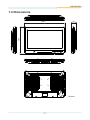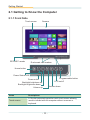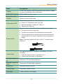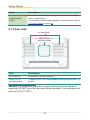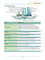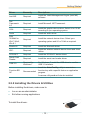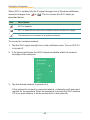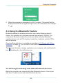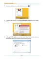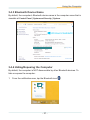
1
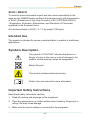
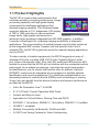
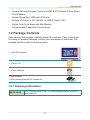
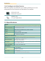
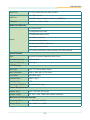
M2150 21.5” Fanless Intel® Medical Station User's Manual Version 1.0 P/N: 4012215000100P 2014.12 This page is intentionally left blank. - II - Revision History Version Date Descriptions 1.0 2014.12 Initial release -i- Copyright Copyright © 2014 ARBOR Technology Corp. All Rights Reserved. This document contains proprietary information protected by copyright. No part of this manual may be reproduced by any mechanical, electronic, or other means in any form without prior written permission of the manufacturer. Disclaimer The information in this document is subject to change without prior notice in order to improve the reliability, design and function. It does not represent a commitment on the part of the manufacturer. Under no circumstances will the manufacturer be liable for any direct, indirect, special, incidental, or consequential damages arising from the use or inability to use the product or documentation, even if advised of the possibility of such damages. About This Manual This user’s manual provides the general information and installation instructions for the product. The manual is meant for the experienced users and integrators with hardware knowledge of personal computers. If you are not sure about any description in this manual, consult your vendor before further handling. We recommend that you keep one copy of this manual for the quick reference for any necessary maintenance in the future. Thank you for choosing ARBOR products. - ii - Contents Contents Preface...........................................................................................................v Declaration of Conformity.......................................................................................v CE....................................................................................................................v FCC Class B....................................................................................................v IEC 60601-1/EN60601-1/EN60601-1-2..........................................................vi RoHS..............................................................................................................vi SVHC / REACH............................................................................................. vii Intended Use........................................................................................................ vii Symbols Description............................................................................................. vii Important Safety Instructions................................................................................ vii General Cleaning Tips............................................................................................x Cleaning Tools.................................................................................................x Recommended Cleaning Procedures.............................................................xi Disposing of the Computer................................................................................... xii Additional Information & Technical Support......................................................... xiii Warranty.............................................................................................................. xiv Chapter 1. Introduction.................................................................................1 1.1 Product Highlights............................................................................................2 1.2 Package Contents............................................................................................3 1.2.1 Ordering Information...............................................................................3 1.2.2 Configure-to-Order Service.....................................................................4 1.3 Specifications...................................................................................................4 1.4 Dimensions.......................................................................................................7 Chapter 2. Getting Started............................................................................9 2.1 Getting to Know the Computer.......................................................................10 2.1.1 Front Side.............................................................................................10 2.1.2 Rear Side..............................................................................................12 2.1.3 Bottom Side..........................................................................................13 2.2 Drivers and Utilities Installation......................................................................14 2.2.1 CD Contents.........................................................................................14 2.2.2 Installing the Drivers & Utilities.............................................................15 Chapter 3. Using the Computer..................................................................17 3.1 Using Touch Screen........................................................................................18 3.1.1 Projected Capacitive Touch.................................................................18 3.1.2 Text Input..............................................................................................18 3.1.2.1 On-screen Keyboard............................................................18 - iii - Contents 3.1.2.2 Handwriting Recognition......................................................19 3.2 Function Keys.................................................................................................20 3.2.1 Specifying the Function Keys...............................................................20 3.2.2 Using the Function Keys.......................................................................22 3.3 Using the Wi-Fi Feature..................................................................................23 3.4 Using the Bluetooth Feature...........................................................................25 3.4.2 Pairing/Connecting with Other Bluetooth Devices................................25 3.4.3 Bluetooth Device Name........................................................................27 3.4.4 Hiding/Exposing the Computer.............................................................27 3.5 Using the Smart Card Reader........................................................................29 3.6 Using the NFC Feature...................................................................................29 3.7 Using the Camera Feature.............................................................................30 3.7.1 Taking a Picture....................................................................................30 3.7.2 Recording a Video................................................................................31 3.7.3 Configuring Video Recording................................................................31 3.8 Attaching to a VESA Mount............................................................................32 Chapter 4. BIOS...........................................................................................33 4.1 Accessing the BIOS Setup Utility....................................................................34 4.2 Main Setup.....................................................................................................35 4.3 Advanced Settings..........................................................................................36 4.3.1 ACPI Settings........................................................................................37 4.3.2 CPU Configuration................................................................................38 4.3.3 SATA Configuration...............................................................................39 4.3.4 AMT Configuration................................................................................40 4.3.5 USB Configuration................................................................................42 4.3.6 F81216 Secondary Super IO Configuration..........................................44 4.4 Chipset...........................................................................................................45 4.4.1 PCH IO Configuration...........................................................................46 4.4.2 System Agent (SA) Configuration.........................................................47 4.4.2.1 Graphics Configuration........................................................48 4.4.2.2 Memory Configuration..........................................................49 4.5 Boot................................................................................................................50 4.6 Security...........................................................................................................52 4.7 Save & Exit.....................................................................................................53 - iv - Preface Preface Declaration of Conformity CE The CE symbol on your product indicates that it is in compliance with the directives of the Union European (EU). A Certificate of Compliance is available by contacting Technical Support. This product has passed the CE test for environmental specifications when shielded cables are used for external wiring. We recommend the use of shielded cables. This kind of cable is available from ARBOR. Please contact your local supplier for ordering information. FCC Class B This device complies with Part 18 of the FCC Rules. Operation is subject to the following two conditions: 1. This device may not cause harmful interference, and 2. This device must accept any interference received, including interference that may cause undesired operation. Any changes or modifications not expressly approved by the guarantee of this device could void the user’s authority to operate the equipment. This equipment has been tested and found to comply with the limits for a Class B digital device, pursuant to Part 18 of the FCC Rules. These limits are designed to provide reasonable protection against harmful interference in a residential installation. This equipment generates, uses and can radiate radio frequency energy and, if not installed and used in accordance with the instructions, may cause harmful interference to radio communications. However, there is no guarantee that interference will not occur in a particular installation. If this equipment does cause harmful interference to radio or television reception, which can be determined by turning the equipment off and on, the user is encouraged to try to correct the interference by one or more of the following measures: • • Reorient or relocate the receiving antenna. • • Increase the separation between the equipment and receiver. -v- Preface • • Connect the equipment into an outlet on a circuit different from that to which the receiver is connected. • • Consult the dealer or an experienced radio/TV technician for help. IEC 60601-1/EN60601-1/EN60601-1-2 • • This product complies with the system standard IEC 60601-1 Medical Electrical Equipment Part 1: General Requirements for Safety. And therefore, the product is exclusively interconnected with IEC 60601-1 certified equipment in the patient environment. • • Equipment connected to the analog or digital interfaces of the unit must comply with the respective IEC standards (e.g. IEC 60601-1 for medical equipment). Furthermore all configurations shall comply with the current version of the standard for SYSTEMS IEC 60601-1-1. • • Everybody who connects additional equipment to the signal input part or signal output part configures a medical system, and is therefore responsible that the system complies with current version of the requirements of the system standard IEC 60601-1-1. If in doubt, consult the technical service department or your local representative. RoHS ARBOR Technology Corp. certifies that all components in its products are in compliance and conform to the European Union’s Restriction of Use of Hazardous Substances in Electrical and Electronic Equipment (RoHS) Directive 2002/95/EC. The above mentioned directive was published on 2/13/2003. The main purpose of the directive is to prohibit the use of lead, mercury, cadmium, hexavalent chromium, polybrominated biphenyls (PBB), and polybrominated diphenyl ethers (PBDE) in electrical and electronic products. Member states of the EU are to enforce by 7/1/2006. ARBOR Technology Corp. hereby states that the listed products do not contain unintentional additions of lead, mercury, hex chrome, PBB or PBDB that exceed a maximum concentration value of 0.1% by weight or for cadmium exceed 0.01% by weight, per homogenous material. Homogenous material is defined as a substance or mixture of substances with uniform composition (such as solders, resins, plating, etc.). Lead-free solder is used for all terminations (Sn(96-96.5%), Ag(3.0-3.5%) and Cu(0.5%)). - vi - Preface SVHC / REACH To minimize the environmental impact and take more responsibility to the earth we live, ARBOR hereby confirms all products comply with the restriction of SVHC (Substances of Very High Concern) in (EC) 1907/2006 (REACH --Registration, Evaluation, Authorization, and Restriction of Chemicals) regulated by the European Union. All substances listed in SVHC < 0.1 % by weight (1000 ppm) Intended Use This product is intended for use as a medical station in medical or healthcare applications. Symbols Description This symbol of “CAUTION” indicates that there is a danger of injury to the user or a risk of damage to the product, should warning notices be disregarded. Battery Recycle This symbol indicates electrical warning. Refer to the user manual for more information. Important Safety Instructions Read these safety instructions carefully: 1. Read all cautions and warnings on the equipment. 2. Place this equipment on a reliable surface when installing. Dropping it or letting it fall may cause damage 3. Make sure the correct voltage is connected to the equipment. - vii - Preface 4. To avoid risk of electric shock, this equipment must only be connected to a supply mains with protective earth. 5. For pluggable equipment, the socket outlet should be near the equipment and should be easily accessible. 6. Keep this equipment away from humidity. 7. Disconnect this equipment from the A/C outlet before cleaning it. Use a moist cloth. Do not use liquid or sprayed detergent for cleaning. 8. To fully disengage the power to the unit, please disconnect the power from the AC outlet. 9. Do not scratch or rub the screen with a hard object. 10. Never use any of the solvents, such as Thinner Spray-type cleaner, Wax, Benzene, Abrasive cleaner, Acid or Alkaline solvent, on the display. Harsh chemicals may cause damage to the cabinet and the touch sensor. 11. Remove dirt with a lightly moistened cloth and a mild solvent detergent. Then wipe the cabinet with a soft dry cloth. 12. The openings on the enclosure are for air convection and protect the equipment from overheating. DO NOT COVER THE OPENINGS. 13. Position the power cord so that people cannot step on it. Do not place anything over the power cord. 14. If the equipment will not be used for a long time, disconnect it from the power source to avoid damage by transient overvoltage. 15. Never pour any liquid into openings. This may cause fire or electrical shock. 16. Never open the equipment. For safety reasons, the equipment should be opened only by qualified service personnel. 17. No modification of the equipment is allowed. 18. Only personnel authorised by the manufacturer may carry out technical operations on the equipment. 19. The sound pressure level at the operator’s position, according to IEC 7041:1982, is no more than 70dB(A). 20. Keep this User’s Manual for later reference. - viii - Preface 21. DO NOT LEAVE THIS EQUIPMENT IN AN UNCONTROLLED ENVIRONMENT WHERE THE STORAGE TEMPERATURE IS BELOW -20° C (-4° F) OR ABOVE 60° C (140° F). THIS MAY DAMAGE THE EQUIPMENT. 22. If one of the following situations arises, get the equipment checked by service personnel: a. The power cord or plug is damaged. b. Liquid has penetrated into the equipment. c. The equipment has been exposed to moisture. d. The equipment does not work well, or you cannot get it to work according to the user’s manual. e. The equipment has been dropped or damaged. f. The equipment has obvious signs of breakage. Do not use the power adapter that isn’t made for the equipment. Supplying the equipment with inappropriate voltage may cause harm to the battery (if any) or, even worse, burn the equipment. Risk of explosion if RTC (Real-Time Clock) battery is replaced by an incorrect type. Dispose of used batteries according to the instructions. To prevent possible hearing damage, do not listen at high volume levels for long periods - ix - Preface General Cleaning Tips You may need the following precautions before you begin to clean the device. When you clean any single part or component for the device, please thoroughly read and understand the details below. 1. We strongly recommended that you should shut down the system before you start to clean any single components. 2. When you need to clean the device, please rub it with a piece of dry cloth. 3. Be cautious of the tiny removable components when you use a vacuum cleaner to absorb the dirt on the floor. 4. Never drop the components inside the device or get circuit board damp or wet. 5. Be cautious of all kinds of cleaning solvents or chemicals when you use it for the sake of cleaning. Some individuals may be allergic to the ingredients. 6. Try not to put any food, drink or cigarette around the device. Cleaning Tools Although many companies have created products to help improve the process of cleaning your devices and peripherals, users can also use household items to clean their devices and peripherals. Below is a listing of items you may need or want to use while cleaning your devices or peripherals. Keep in mind that some components in your device may only be able to be cleaned using a product designed for cleaning that component, if this is the case it will be mentioned in the cleaning. • Cloth: A piece of cloth is the best tool to use when rubbing up a component. Although paper towels or tissues can be used on most hardware as well, we still recommend you to rub it with a piece of cloth. • Water or rubbing alcohol: You may moisten a piece of cloth a bit with some water or rubbing alcohol and rub it on the device. Unknown solvents may be harmful to the plastics parts. • Vacuum cleaner: Absorb the dust, dirt, hair, cigarette particles, and other particles out of the device can be one of the best cleaning methods. Over -x- Preface time, these items can restrict the airflow in a device and cause circuitry to corrode. • Cotton swabs: Cotton swaps moistened with rubbing alcohol or water are excellent tools for wiping hard to reach areas in your keyboard, mouse, and other locations. • Foam swabs: Whenever possible, it is better to use lint-free swabs such as foam swabs. Recommended Cleaning Procedures 1. Close all application programs 2. Close operating software 3. Turn off power switch 4. Remove all peripherals 5. Pull out power cable - xi - Preface Disposing of the Computer • • Within the European Union EU-wide legislation, as implemented in each Member State, requires that waste electrical and electronic products carrying the mark (left) must be disposed of separately from normal household waste. This includes monitors and electrical accessories, such as signal cables or power cords. When you need to dispose of your display products, please follow the guidance of your local authority, or ask the shop where you purchased the product, or if applicable, follow any agreements made between yourself. The mark on electrical and electronic products only applies to the current European Union Member States. • • Outside the European Union If you wish to dispose of used electrical and electronic products outside the European Union, please contact your local authority so as to comply with the correct disposal method. - xii - Preface Additional Information & Technical Support All ARBOR products are built to the most accurate specifications to ensure reliable performance in the harsh and demanding conditions typical of industrial environments. Whether your new equipment is destined for the laboratory or the factory floor, you can be assured that the computer will provide the reliability and ease of operation. Your satisfaction is our primary concern. We want you to get the maximum performance from the computer. So if you run into technical difficulties, we are here to help. For the most frequently asked questions, you can easily find answers in the computer’s documentation. These answers are normally a lot more detailed than the ones we can give over the phone. So please consult this manual first. If you still cannot find the answer, gather all the information or questions that apply to your problem, and with the product close at hand, call your dealer. Our dealers are well trained and ready to give you the support you need to get the most from the computer. In fact, most problems reported are minor and are able to be easily solved over the phone. We are always ready to give advice on application requirements or specific information on the installation and operation of any of our products. Do not hesitate to contact us: Webite: http://www.arbor.com.tw E-mail: [email protected] TEL: 886-2-8226-9396 Add: 10F., No.700, Zhongzheng Rd., Zhonghe Dist., New Taipei City 235, Taiwan - xiii - Preface Warranty This product is warranted to be in good working order during the warranty period. Should this product fail to be in good working order at any time during this period, we will, at our option, replace or repair it at no additional charge except as set forth in the following terms. This warranty does not apply to products damaged by misuse, modifications, accident or disaster. Vendor assumes no liability for any damages, lost profits, lost savings or any other incidental or consequential damage resulting from the use, misuse of, or inability to use this product. Vendor will not be liable for any claim made by any other related party. Vendors disclaim all other warranties, either expressed or implied, including but not limited to implied warranties of merchantability and fitness for a particular purpose, with respect to the hardware, the accompanying product’s manual(s) and written materials, and any accompanying hardware. This limited warranty gives you specific legal rights. Return authorization must be obtained from the vendor before returned merchandise will be accepted. Authorization can be obtained by calling or faxing the vendor and requesting a Return Merchandise Authorization (RMA) number. Returned goods should always be accompanied by a clear problem description. - xiv - Preface 1 Chapter 1 Introduction Chapter 1. Introduction -1- Introduction 1.1 Product Highlights The M2150 is a well-suited medical station that combines powerful computing performance, image processing capability and high grade display components for healthcare applications that demand imaging capability. This Windows-based computer features a 21.5” widescreen LCD display of 1920 x 1080 resolution to offer exceptional image clarity. High graphic performance is achieved via the processor-integrated Intel HD 4600 graphics. In addition, it includes a Displayport for increasing imaging productivity in diagnostic applications. The communication of medical images can be further enhanced by the integrated 5MP camera. Together with the powerful Intel Core i5 onboard CPU, the M2150 is genuinely suited for medical imaging applications such as PACS. To cater a variety of medical equipments, the M2150 supports an array of advanced I/O ports, including USB 3.0/2.0 ports, Gigabit LAN port, serial port, video out and audio in/out. Plus, the LAN, serial and USB ports are 4KV isolated to ensure that the M2150 will not interfere with the connected medical instruments. As an added convenience, it provides two smart card readers for identifications, one for clinical staff and the other for patients. Optional RFID/NFC module can be integrated as an expansion to facilitate patients identification and records management. For healthcare professionals to run demanding electronic medical records (EMRs) such as radiology or viewing X-rays, they can benefit from the diverse functions and superior performance provided by the M2150. • • Intel® 4th Generation Core™ i5-4422E • • 21.5” LCD with 10-point Capacitive Multi-Touch • • Fanless and Easy-to-clean • • Applicable for Clinical Station, Nursing Care and PACS • • IEC60601-1 (3rd edition), EN60601-1 (3rd edition), EN60601-1-2 certified • • UL60601-1 compliant • • Multiple Connectivity via Bluetooth, WLAN and GbE • • 5.0 MP Front-Facing Camera for Video Conferencing -2- Introduction • • System Security & Access Control via RFID & NFC Reader & Dual Smart Card Readers • • Isolated Serial Port, USB and LAN Ports • • Multiple I/O Ports (1x RS-232/485, 4x USB 3.0 and 1x DP) • • Stylish Flush Front Bezel with Slim Borders • • Programmable Capacitive Function Keys 1.2 Package Contents Upon opening the package, carefully inspect the contents. If any of the items is missing or appears damaged, contact your local dealer or distributor. The package should contain the following items: 1 x M2150 Computer 1 x Driver CD 1 x User’s Manual Power Adapter 100W medical-grade AC/DC adapter kit 1.2.1 Ordering Information M2150-4422E 21.5” Fanless Intel® Core™ i5-4422E Medical Station with Wi-Fi and Bluetooth -3- Introduction 1.2.2 Configure-to-Order Service Make the computer more tailored to your needs by selecting one or more components from the list below to be fabricated to the computer. RFID & NFC-2150 RFID & NFC Combo Kit SSD80G-215X 2.5” Intel® 80GB SSD Kit 1.3 Specifications System CPU Soldered Onboard 4th Generation Intel® Core™ i5-4422E 1.8 GHz Graphics Controller Intel® HD Graphics 4600 Memory 4GB DDR3L SO-DIMM memory module installed Chipset Intel® PCH QM87 Storage 32GB mSATA MLC SSD installed 2.5” 80GB SSD (optional) Peripherals and Devices Camera 1 x 5.0 MP front-facing CMOS camera with auto-focus WLAN & Bluetooth 1 x IEEE 802.11 ac/a/b/g/n and Bluetooth 4.0 LE, Class 1 RFID & NFC 1 x 13.56MHz RFID & NFC reader with ISO 14443A/14443B/15693 reader support (optional) Smart Card Reader 2 x Smart Card Reader slots I/O Interface Audio 2 x 2W speakers 1x MIC-In, 1x Line-out Video output 1 x DisplayPort LAN 2 x Intel® GbE RJ-45 with 4KV isolation -4- Introduction Serial Port USB Port Expansion 1 x RS-232/485 port with 4KV isolation 4 x USB 3.0 ports 1 x USB 2.0 port with 4KV isolation (12MB/Bits) 1 x PCIe x16 (Max. 20W) Button & Indicator 1 x Home button 1 x Brightness up button 1 x Brightness down buton Button 1 x Volume up button 1 x Volume down button 1 x Touch and LCD on/off button 1 x Programmable button 1 x Power on/off switch (at the bottom) with LED Indicator Touch Screen Type 10-point Projected Capacitive Multi-Touch Controller Interface USB interface Light Transparency 91% (typ.) LCD Display Size/Type 21.5” TFT Active Matrix Panel Max. Resolution 1920 x 1080 with 16.7M colors Luminance 250 cd/m² (typ.) Contrast Ratio 1000:1 (typ.) Backlight Type LED View Angle (U/D/R/L) 85°/85°/80°/80° (typ.) Power Requirement Adapter Input 100 ~ 240 VAC (full range) Adapter Output DC 18V, 5.55A, 100W with medical certificate Mechanical & Environmental Operating Temp. 0 ~ 40ºC (32 ~ 104ºF) Storage Temp. -20 ~ 60ºC (-4 ~ 140ºF) -5- Introduction Operating Humidity 10 ~ 95% @ 40ºC (non-condensing) Dimensions (W x H x D) 546 x 383 x 63 mm (21.5”” x 15.08” x 2.48”) Net Weight 6.8 kg (14.99 lb) Vibration 5 ~ 500Hz, 1G random operation Shock 10G peak (11m/sec) Mounting VESA-75/100 compatible (M4) IP Rating Compliance design with IP65 (front touch panel) Operational Altitude Below 2000m CE, FCC Class B Regulatory IEC60601-1 (3rd edition), EN60601-1 (3rd edition), EN60601-1-2 UL60601-1 compliant OS Support Windows Embedded Standard 7 (WS7P) Windows Embedded 8 Standard / Windows Embedded 8.1 Industry Pro Linux: Ubuntu / Fedora -6- Introduction 1.4 Dimensions 63 383 546 Unit:mm -7- This page is intentionally left blank. -8- 2 Chapter 2 Getting Started Chapter 2. Getting Started -9- Getting Started 2.1 Getting to Know the Computer 2.1.1 Front Side Touch screen RFID/NFC reader Camera Dual smart card readers Home button Power Status LED Programmable button Power on/off Backlight brightness up Backlight brightness down Volume up LCD on/off Volume down Items Descriptions Touch screen A 10-point projected capacitive multi-touch screen allowing users to interact with the computer without a mouse or keyboard. - 10 - Getting Started Items Descriptions Camera 5.0 MP front-facing CMOS camera with auto-focus for taking pictures or holding a video conference. RFID & NFC Reader RFID & NFC detection area. Dual Smart Card Readers Smart card reader slots. Allows to insert smart cards. Shows the power status of the computer. Power status LED XX Power off / Hibernate mode: No light XX Normal operation / display off: Light on XX Sleep mode: Blinking Press and then release the button to perform these tasks: XX To power on/off the computer. XX To wake the computer from hibernate or sleep mode. XX Power Switch Home button If the system becomes unresponsive, press the hold the power switch for at least 3 seconds to force computer to restart. Note: The power switch will return to the “I” position when released. The operating system’s “physical” Start button to do the following: XX Open the Start screen in Windows 8 / 8.1 XX Launch the Start menu in Windows 7 Backlight brightness up Increases LCD backlight brightness Backlight brightness down Decreases LCD backlight brightness Volume up Increases system volume Volume down Decreases system volume LCD on/off Turns on/off the LCD display. - 11 - Getting Started Items Programmable button Descriptions Executes a certain Windows program or function according to user’s customization. To customize functions and programs for quick access, refer to 3.2 Function Keys on page 20. 2.1.2 Rear Side Air ventilation VESA75/100 mounting holes Item Descriptions Air ventilation Air ventilation for the computer. VESA 75/100 mounting holes To attach VESA 75/100-compatible mounting kit using M4 x 12 screws . Warning: The computer’s rear plate is highly heated when the computer is operating. DO NOT touch the rear plate during operating. The temperature will reach up to 60°C (140ºF). - 12 - Getting Started 2.1.3 Bottom Side DP Port Dual LAN ports w/ 4KV isolation USB 2.0 port w/ 4KV isolation Line-out & MIC USB 3.0 ports DC-in COM port w/ 4KV isolation PCIe x 16 Slot (Covered) Speakers Items Dual Smart Card Readers Descriptions PCIe x16 expansion slot (Max. 20W) PCIe x16 Slot COM Port USB 2.0 Port Dual LAN Ports DP Line-out Warning: The PCIe expansion module is a configured-to-order service. You are not allowed to open the rear plate of the M2150 to add or replace the PCIe expansion module, otherwise the warranty is void. RS-232/485 DB-9 serial port with 4KV isolation To connect to a serial device. USB 2.0 Type-A port with 4KV isolation To connect to a USB device. Intel Gigabit LAN connectors with 4KV isolation To connect to the computer to a network. DisplayPort v1.2 To connect to a HDMI monitor or projector. To connect to a headphone. 3.5mm microphone jack. MIC To connect to a microphone to capture sound and voice when used with a program capable of recording audio. - 13 - Getting Started Items Descriptions USB 3.0 Type A port, backwards compatible with USB 2.0 & 1.1. USB 3.0 Port To connect to a USB device. Note: For Windows 7, make sure to install USB 3.0 driver on the provided CD. Power jack. DC-IN To connect to the power adapter to provide power to the computer. Speaker Integrated 2W stereo speakers for audio output. Dual Smart Card Readers Smart card reader slots. Allows to insert smart cards. Protective Earth (ground) 2.2 Drivers and Utilities Installation The computer comes with a CD that contains device drivers as well as some programs and utilities. You need to install the drivers to activate the devices and some device-related services. Some drivers will come with driver-related programs to facilitate the application. To install the drivers and utilities, make sure to follow the instructions (e.g., the installation sequence) given in this section to proceed. In addition, the CD includes a number of optional utilities. You may install those utilities as needed. 2.2.1 CD Contents The drivers and utilities included in the CD are described in the table below: Driver Necessity Chipset Required Descriptions Install the chipset driver to the computer. Make sure to install the chipset driver before installing other drivers to prevent errors. - 14 - Getting Started Driver Necessity Descriptions Intel ME Required Install the Intel® Management Engine (Intel ME) software. Net Framework 4.0 Required Install Microsoft .NET framework VGA Required Install the graphic device driver. Select 64 or 32-bit according to your operating system. Audio Required Install the audio driver. LAN 32/64bit for Win7, Win8, Win 8.1 Required Install the network device driver. Select your operating system and 64 or 32-bit as required. Bluetooth Required Install the Bluetooth driver. WiFi Required Install the wireless network device driver and client utilties. RFID/NFC Required Install the RFID/NFC device driver. Smart Card Reader Required Install the smart card reader driver. USB 3.0 Required for Windows 7 For Windows 7, install the USB driver to use the USB 3.0 interface. Recommended Install the ArborFunKey utility to associate a function key with a specific feature or application program. Function BD AP A camera utility ccdc will also be installed. 2.2.2 Installing the Drivers & Utilities Before installing the drivers, make sure to: • • Lon on as an administrator • • Exit other running applications To install the drivers: - 15 - Getting Started 1. Connect a USB CD-ROM drive (not provided) to the computer. According to your CD-ROM drive, you may need to connect it to a power supply. 2. Insert the provided CD to the CD-ROM drive. In a few seconds, a dialog box opens asking what to do with the disc. Tap Run AUTORUN.EXE to auto-run the driver CD. 3. Tap Driver Install. 4. The drivers menu then opens. 5. Follow the sequence below to install the driver: Chipset → IntelME → .Net Framework → VGA → Audio → Other Drivers / Utilities The installation process of each driver is basically the same. Just follow the on-screen instructions to proceed. If prompted to restart the computer, tap Yes to do so. In some cases, User Access Control will appear asking for permission to make changes to the computer. Simply tap Yes to continue. - 16 - 3 Chapter 3 Using the Computer Chapter 3. Using the Computer - 17 - Using the Computer 3.1 Using Touch Screen The computer comes with a projected capacitive touch screen. Touch control is the main way and an intuitive way to interact with the computer. Users are able to manipulate icons, graphic buttons, menus, property sheets, the on-screen keyboard or any on-screen items with touch control. This chapter will walk you through the basic operations for touch control. 3.1.1 Projected Capacitive Touch Unlike the resistive touch, the projected capacitive touch works by the change of capacitance when a conductive object, such as a finger, contact the touch screen. Hence it requires only a human finger and zero force to trigger actions from the projected capacitive touch screen. And no calibration is needed. If the computer runs Windows 7/8, the projected capacitive touch screen is ready to function when the computer is delivered. No driver is needed. 3.1.2 Text Input The computer doesn't have a physical keyboard to receive user's text input. To input text on the computer, it relies on either an external USB keyboard, or the "on-screen keyboard", or the Windows-featured handwriting recognition. 3.1.2.1 On-screen Keyboard An "on-screen keyboard" is a virtual keyboard with all the standard keys. With Windows you can use either a touch keyboard or thumb keyboard to facilitate text input. To open the Windows on-screen keyboard: 1. Tap the keyboard icon on the Windows taskbar. 2. The Input Panel opens in either keyboard mode or handwriting mode, according to your previous use. Tap the icon in the lower right corner to switch between the modes. - 18 - Using the Computer The thumb keyboard The touch keyboard The handwriting panel Exit the on-screen keyboard 3. To use the touch or thumb keyboard, just enter text by tapping the keys. 3.1.2.2 Handwriting Recognition “Handwriting Recognition” is an input method that interprets and converts handwriting to text. The Windows features a “writing pad” to get the job done. To launch the Windows handwriting panel: 1. Tap the keyboard icon on the Windows taskbar to open the Input Panel as described in 3.1.2.2 Handwriting Recognition on page 19. If it’s in keyboard mode, tap the icon in the lower right corner and tap the handwriting icon to switch to handwriting mode. - 19 - Using the Computer 2. Write in the writing area. Then tap the bottom-right Enter button to enter the text in a text field. 3.2 Function Keys 3.2.1 Specifying the Function Keys The computer comes with a programmable function key enabling you to quickly execute certain programs or functions. To use this function: 1. Install the ARBOR Function Key utility using the provided CD as described in 2.2 Drivers and Utilities Installation on page 14. 2. To assign a function to the key, tap the up arrow on the taskbar to bring up the notification area. - 20 - Using the Computer 3. Tap and hold the ArborFunKey icon to bring up its context menu and then tap Set Function Keys. 4. Tap the Browse button and then select the executable file of the program that you want to associate. 5. Assigned file name will appear on the panel to indicate the assignment is done. - 21 - Using the Computer 3.2.2 Using the Function Keys To use the function keys, you can press the keys on the front bezel below the LCD viewing screen: Or, you can launch the ArborFunKey control UI on the Windows by either of the following methods: 1. Double-click the ArborFunKey shortcut icon on the desktop. 2. Tap Start > All programs > ArborFunKey > ArborFunKey on Windows 7 or tap the ArborFunKey icon on All Apps list on Windows 8 / 8.1. 3. Tap the up arrow on the taskbar to bring up the notification area and then double-tap the ArborFunKey icon. Then the Windows UI will appear on the lower right corner of the desktop. - 22 - Using the Computer The UI provide the following functions: Icon Descriptions Decreases system volume Increases system volume Decreases LCD backlight brightness Increases LCD backlight brightness Launches user-specified application or function. Program Press and hold for 3 seconds to simulate the behavior of the CTRL+ALT+DEL key combination. Restore Defaults Restores defaults. The volume and LCD brightness will be restored to the default level and the program button will have no function. Close To close the Arbor Function Key utility UI. 3.3 Using the Wi-Fi Feature The computer is built-in with a Wi-Fi module for Wi-Fi networking. Once the driver is installed as described in 2.2 Drivers and Utilities Installation on page 14, a Wi-Fi signal strength icon shows up in the notification area. Wi-Fi icon in the notification area - 23 - Using the Computer When Wi-Fi is enabled, the Wi-Fi signal strength icon in Windows notification area also changes from described below: Icon to . The icon shows the Wi-Fi status as Descriptions Wi-Fi is disabled. Wi-Fi is enabled and there are available wireless networks in range. The computer is connected to a wireless network. To connect to a wireless network: 1. Tap the Wi-Fi signal strength icon in the notification area. Turn on WiFi if it is turned off. 2. A list opens and shows the Wi-Fi hotspots available within the wireless coverage of the computer. 3. Tap the desired network to connect to it. If the network to connect is a secured network, a dialog box will open and request for the password. Enter the password to access the Wi-Fi network. If it is an open network, it will be connected in a few seconds. - 24 - Using the Computer 4. When the computer is connected to a Wi-Fi network, “Connected” will be displayed and the Wi-Fi signal strength icon in the notification area changes to . 3.4 Using the Bluetooth Feature Bluetooth enables the wireless connection over a short distance about 8 meters. It is specified as a “wireless personal area network” (WPAN). The computer is Bluetooth-enabled to synchronize data with other Bluetoothcapable devices such as PCs, laptops, hands-free, headsets, printers, PDAs and cell phones. Once the Bluetooth driver is installed as described in 2.2 Drivers and Utilities Installation on page 14, you can start to use the Bluetooth function. The Bluetooth function is always enabled on your computer, with the Bluetooth icon displabyed in the notification area. 3.4.2 Pairing/Connecting with Other Bluetooth Devices Before the computer can connect with other Bluetooth devices, it has to pair with them. To pair/connect with other Bluetooth devices: - 25 - Using the Computer 1. From the notification area, tap the Bluetooth icon . 2. A context menu opens. Select Add a Bluetooth Device from the context menu. 3. A Manage Bluetooth devices window opens. Select the Bluetooth device to connect and follow the on-screen instructions to proceed. - 26 - Using the Computer 3.4.3 Bluetooth Device Name By default, the computer’s Bluetooth device name is the computer name that is viewable at Control Panel | System and Security | System. 3.4.4 Hiding/Exposing the Computer By default, the computer is NOT discoverable by other Bluetooth devices. To hide or expose the computer: 1. From the notification area, tap the Bluetooth icon - 27 - . Using the Computer 2. A context menu opens. Select Open Settings from the context menu. 3. The Bluetooth Settings dialog box then opens. Tap the Options tab and find the Discovery section. To make your computer discoverable to Bluetooth enabled devices, select the check box of Allow Bluetooth devices to find this computer or otherwise deselect the check box to make it undiscoverable. - 28 - Using the Computer 3.5 Using the Smart Card Reader The computer is equipped with two smart card readers that allow users to provide identification and information using a smart card. To use a smart card, insert the card with the golden chip facing upward as shown below: 3.6 Using the NFC Feature Near Field Communication (NFC) is a short-range wireless communication technology that enables NFC-capable devices to exchange data such as contacts, photos, music, or web address over a short distance less than 4 centimeters. The NFC detection area is on the front bezel below the LCD viewing screen as the icon indicates. When you tap other NFC devices, tags, or readers, the NFC areas of both devices should be close to one another so that the connection can be established. - 29 - Using the Computer 3.7 Using the Camera Feature The computer comes with a ready-to-use camera without the need to install additional drivers. You can use Windows or third-party camera utility with the camera to take pictures, record videos or participate in a video conference. Alternatively you can use the ccdc camera utility, which will be installed when you install the ArborFunKey utility. To launch the ccdc camera utility: Tap Start > All programs > ArborFunKey > ccdc on Windows 7 or tap the ccdc icon on All Apps list on Windows 8 / 8.1. Subject scene Enables/mutes shutter audio Tool bar Video Shooting Settings Closes camera program Takes a picture Shoots a video 3.7.1 Taking a Picture To take a picture: 1. From the ccdc camera utility tool bar, tap the take-a-picture icon . 2. The camera then proceeds to take a picture and save it to the local disk. The default location is: C:\Users\<your user name>\Documents\ccd - 30 - Using the Computer 3.7.2 Recording a Video To record a video: 1. From the ccdc camera utility tool bar, tap the record-a-video icon The icon then changes to an in-recording button recording starts. . , and video 2. Tap the in-recording button again to stop recording. The video shot will be saved to the local disk. The default location is: C:\Users\<your user name>\Documents\ccd 3.7.3 Configuring Video Recording To configure the video recording settings: 1. From the camera utility’s tool bar, tap the configuration icon The Properties dialog box opens. 2. Make the configuration as needed. - 31 - . Using the Computer 3. Tap the Apply button to apply the changes. 383 3.8 Attaching to a VESA Mount The computer supports 75 and 100mm VESA mount so you can attach the computer to a VESA mount kit. To attach the computer to a VESA mount kit: 1. Locate the four VESA mounting holes on the rear of the computer. 2. Attach your VESA mount kit to the rear of the computer by matching the mounting holes with the VESA mount kit. 3. Fix the assembly with M4 x 12 screws. VESA100 mounting holes VESA75 mounting holes Unit:mm - 32 - 4 Chapter 4 BIOS Chapter 4. BIOS - 33 - BIOS A BIOS (Basic Input/Output System) is a special utility usually stored in the ROM on the motherboard inside a computer. When you turn on the computer, the BIOS is immediately activated. During the startup, it checks and loads necessary information to ensure the computer can proceed with loading the operating system. The BIOS Setup Utility is typically accessed with a special key sequence, such as “Delete” or “Esc” key as soon as the computer is powering up. Once you have entered the BIOS, you can get some system information and configure some hardware parameters. In most cases, there will be no need to make adjustments to the BIOS. The default settings apply to most applications and provide optimal performance. Caution: If you need to make any change, be careful when making changes to the BIOS. Incorrect settings can cause system boot failure or malfunction. Note: For system stability and performance, this BIOS utility is constantly improved. The screenshots demonstrated and descriptions hereinafter are for reference only and may not exactly meet what is presented on-screen. 4.1 Accessing the BIOS Setup Utility To enter and use the BIOS Setup Utility, prepare a USB keyboard first and then: 1. Connect the USB keyboard to the computer first. 2. Power on the computer and press the “Delete” or “Esc” key immediately after powering on. 3. Then you will enter the BIOS Setup Utility and see the Main setup screen. BIOS Setup Utility is mainly a key-based navigation interface. The bottom of the screen shows the keys for navigation and changing the settings. Refer to the table below for instructions on using the keys. Keys Descriptions F1 Activate “General Help” screen. ← → Move to select a particular configuration screen from the top menu bar / Move to highlight items on the screen. ↓ ↑ Move to select an item. - 34 - BIOS Keys Descriptions Enter Select or enter a submenu Esc On the Main Menu – Exit the setup and not save changes into CMOS. + / F6 Increase a numeric value. - / F5 Decrease a numeric value. F9 Load the optimal defaults. All settings will be set to the optimal defaults at startup. F10 Save the changes that have been made and exit the BIOS Setup Utility. On the Sub Menu – Exit current page and return to main menu. 4.2 Main Setup When you first enter the BIOS Setup Utility, you will enter the Main setup screen. It reports basic system information and also allows you to configure the System Date and System Time settings. Aptio Setup Utility - Copyright (C) 2012 American Megatrends, Inc. Main Advanced Chipset Boot Security Save & Exit BIOS Information BIOS Version EC Version M2150 0.07 0.10 System Date System Time [Wed 11/28/2014] [14:04:38] Access Level Administrator Set the Date. Use Tab to switch between Date elements. →←: Select Screen : Select Item Enter: Select +/-: Change Opt. F1: General Help F2: Previous Values F9: Optimized Defaults F10: Save & Exit ESC: Exit Version 2.15.1236. Copyright (C) 2012 American Megatrends, Inc. - 35 - BIOS The Main setup screen provides the following information and options: Info / Item Descriptions BIOS Version Displays the computer’s model and the BIOS version. EC Version Displays the current version of Embedded Controller. System Date Sets system date. Valid range is from 1 to 12, 1 to 31 and 2000 to 2099. System Time Sets system time. Valid range is from 0 to 23, 0 to 59 and 0 to 59. 4.3 Advanced Settings The Advanced setup screen allows you to change the system and hardware settings. The Advanced screen provides the following setting options: • • 4.3.1 ACPI Settings on page 37 • • 4.3.2 CPU Configuration on page 38 • • 4.3.3 SATA Configuration on page 39 • • 4.3.4 AMT Configuration on page 40 • • 4.3.5 USB Configuration on page 42 • • 4.3.6 F81216 Secondary Super IO Configuration on page 44 Caution: Be careful when making system and hardware changes. Incorrect settings can cause system boot failure or malfunction. - 36 - BIOS Aptio Setup Utility - Copyright (C) 2012 American Megatrends, Inc. Main Advanced Chipset Boot Security Save & Exit ACPI Settings CPU Configuration SATA Configuration AMT Configuration USB Configuration F81216 Secondary Super IO Configuration System ACPI Parameters →←: Select Screen ↓↑: Select Item Enter: Select +/-: Change Opt. F1: General Help F2: Previous Values F9: Optimized Defaults F10: Save & Exit ESC: Exit Version 2.15.1236. Copyright (C) 2012 American Megatrends, Inc. 4.3.1 ACPI Settings The ACPI Settings screen provides the following setting options: Settings Descriptions Enable Hibernation Enables/Disables system ability to hibernation (OS/S4 sleep state). This option may not be effective on some operating systems. Options: Enabled [default], Disabled Sets the highest ACPI sleep state that system enters when the suspend button is hit. Options available are: ACPI Sleep State XX Suspend Disabled XX S1 only (CPU Stop Clock) XX S3 only (Suspend to RAM) XX Both S1 and S3 available for OS choose from - 37 - BIOS 4.3.2 CPU Configuration Access this submenu to identify the CPU and its capabilities by running a report listing the CPU’s model name, processor speed, microcode revision, max./min. processor speeds, processor cores, and so on. Aptio Setup Utility - Copyright (C) 2012 American Megatrends, Inc. Main Advanced Chipset Boot Security Save & Exit CPU Configuration Intel(R) Core(TM) i5-4422E CPU @ 1.60GHz CPU Signature Processor Family Microcode Patch FSB Speed Max CPU Speed Min CPU Speed CPU Speed Processor Cores Intel HT Technology Intel VT-x Technology Intel SMX Technology 64-bit EIST Technology CPU C3 State CPU C6 State CPU C7 State 306c3 6 16 100 MHz 1600 MHz 800 MHz 2600 MHz 2 Supported Supported Supported Supported Supported Supported Supported Supported L1 Data Cache 32 kB x 4 L1 Code Cache 32 kB x 4 L2 Cache 256 kB x 4 L3 Cache 3072 kB →←: Select Screen ↓↑: Select Item Enter: Select +/-: Change Opt. F1: General Help F2: Previous Values F9: Optimized Defaults F10: Save & Exit ESC: Exit Version 2.15.1236. Copyright (C) 2012 American Megatrends, Inc. - 38 - BIOS 4.3.3 SATA Configuration Access this submenu to view SATA device(s) information and also to configure SATA device(s). Aptio Setup Utility - Copyright (C) 2012 American Megatrends, Inc. Advanced Enable or disable SATA Device. SATA Controller(s) SATA Controler Speed [Enabled] [Default] Serial ATA Port 0 Software Preserve Port 0 SATA Device Type Serial ATA Port 1 Software Preserve Port 1 SATA Device Type Serial ATA Port 2 Software Preserve Port 2 SATA Device Type Serial ATA Port 3 Software Preserve Port 3 SATA Device Type Empty Unknown [Enabled] [Hard Disk Drive] mSATA-I50 (32.0GB) Supported [Enabled] [Hard Disk Drive] Empty Unknown [Enabled] [Hard Disk Drive] Empty Unknown [Enabled] [Hard Disk Drive] : Select Screen : Select Item Enter : Select +/- : Change Opt. F1: General Help F2: Previous Values F9: Optimized Defaults F10 : Save & Exit ESC : Exit Version 2.15.1236. Copyritght (C) 2012 American Megatrends, Inc. The SATA Configuration screen provides the following setting options: Settings SATA Controller(s) SATA Controller Speed Descriptions Enables/disables the present SATA controller. Options: Enabled [default], Disabled Sets the maximum speed for the SATA controller to support. Options: Default [default], Gen1, Gen2 and Gen3. Displays the information detected on the installed SATA drive and its security mode. Serial ATA Port 0/1/2/3: Displays the information detected if a SATA device is connected to the indicated SATA port. Serial ATA Port 0/1/2/3 Software Preserve: Indicates whether or not a connected device supports Software Setting Preservation (SSP). Port 0/1/2/3: Enables/disables the SATA port. SATA Device Type: Defines whether the SATA port is connected to a Hard Disk Drive or Solid State Drive. - 39 - BIOS 4.3.4 AMT Configuration Intel® Active Management Technology (Intel® AMT) is a hardware-based solution that uses out-of-band communication for basic management of client systems, which allows a system administrator to monitor and manage the computers and other network equipment by remote control even if the hard drive is crashed, the system is turned off or the operating system is locked. Aptio Setup Utility - Copyright (C) 2011 American Megatrends, Inc. Advanced Intel AMT BIOS Hotkey Pressed MEBx Selection Screen Hide Un-Configure ME Confirmation MEBx Debug Message Output Un-Configure ME Amt Wait Timer Disable ME ASF Activate Remote Assistance Process USB Configure PET Progress AMT CIRA Timeout [Enabled] [Disabled] [Disabled] [Disabled] [Disabled] [Disabled] 0 [Disabled] [Enabled] [Disabled] [Enabled] [Enabled] 0 Enable/Disable Intel (R) Active Management Technology BIOS Extension. Note: iAMT H/W is always enabled. This option just controls the BIOS extension execution. If enabled, this requires additional firmware in the SPI device. : Select Screen : Select Item Enter : Select +/- : Change Opt. F1: General Help F2: Previous Values F9: Optimized Defaults F10 : Save & Exit ESC : Exit Version 2.14.1219. Copyritght (C) 2011 American Megatrends, Inc. The AMT Configuration screen provides the following setting options: Settings Descriptions Enables/disables Intel® Active Management Technology BIOS extensions. Intel AMT BIOS Hotkey Pressed Options: Enabled [default], Disabled Note. iAMT hardware is always enabled. This setting only controls BIOS extension execution. When enabled, additional firmware is required in the SPI device. Enables/disables BIOS Hotkey Press function Options: Enabled, Disabled [Default] - 40 - BIOS Settings Descriptions MEBx Selection Screen Enables/disables MEBx Selection Screen function. Hide Un-Configure ME Confirmation MEBx Debug Message Output Un-Configure ME Amt Wait Timer Disable ME ASF Options: Enabled, Disabled [Default] Enables/disables Hide Un-Configure ME without password Configuration Prompt function. Options: Enabled, Disabled [Default] Enables/disables MEBx Debug Message Output function. Options: Enabled, Disabled [Default] Enables/disables Un-Configure ME without password function. Options: Enabled, Disabled [Default] Set time to wait before sending ASF_GET_BOOT_ OPTIONS. Set ME to soft Temporary Disabled function Options: Enabled, Disabled [Default] Enables/disables Alert Specification Format, a DMTF (Distributed Management Task Force) standard for remote monitoring, management and control of computer system in both OS-present and OS-absent environments. Options: Enabled [default], Disabled Activate Remote Assistance Process USB Configure PET Progress Enables/disables CIRA (Client-Initiated Remote Access) boot. Options: Enabled, Disabled [Default] Enables/disables USB Configure function. Options: Enabled [default], Disabled Enables/disables PET events progress to receive PET event or not. Options: Enabled [default], Disabled CIRA means “Client Initiated Remote Access”. Customizes the time-out for the establishment of MPS connection. AMT CIRA Timeout This setting is only available when Activate Remote Assistance Process is enabled. XX XX Set it to 0 to use the default time-out value of 60 seconds. Set it to 255 to have MEBx wait until the connection succeeds. - 41 - BIOS 4.3.5 USB Configuration Access this submenu to view the USB device(s) enabled in the system. It also configures USB-related features. Aptio Setup Utility - Copyright (C) 2012 American Megatrends, Inc. Main Advanced Chipset Boot Security Save & Exit USB Configuration USB Module version 8.10.28 USB Devices: 1 Keyboard, 1 Point, 5 Hubs, 2 SmartCard Readers Legacy USB Support [Enabled] USB3.0 Support [Enabled] XHCI Hand-off [Enabled] EHCI Hand-off [Disabled] USB Mass Storage Driver Support [Enabled] USB hardware delays and time-outs: USB transfer time-out Device reset time-out Device power-up delay [20 sec] [20 sec] [Auto] Enables Legacy USB support. AUTO option disables legacy support if no USB devices are connected. DISABLE option will keep USB devices available. only for EFI applications. →←: Select Screen ↓↑: Select Item Enter: Select +/-: Change Opt. F1: General Help F2: Previous Values F9: Optimized Defaults F10: Save & Exit ESC: Exit Version 2.15.1236. Copyright (C) 2012 American Megatrends, Inc. The USB Configuration screen provides the following setting options: Settings Descriptions Enables/disables legacy USB support including USB flash drives and USB hard drives. Options available are Legacy USB Support XX XX XX USB3.0 Support Enabled [Default}: To enable legacy USB support. Disabled: To keep USB devices available only for EFI specification, Auto: To disable legacy support if no USB devices are connected. Enables/disables USB 3.0 controller support. Options: Enabled [default], Disabled - 42 - BIOS Settings Descriptions XHCI Hand-off This is a workaround for operating systems without XHCI hand-off support. The XHCI ownership change should be claimed by XHCI driver. Note: For Windows 7, this setting must be disabled. Options: Enabled [default], Disabled EHCI Hand-off This is a workaround for operating systems without EHCI hand-off support. The EHCI ownership change should be claimed by EHCI driver. Note: For Windows 7, this setting must be enabled. Options: Enabled, Disabled [Default] USB Mass Storage Driver Support Enables/disables USB Mass Storage Driver Support. Options: Enabled [default], Disabled This is a submenu to configure the features of USB hardware delay and time-out. The settings include: USB Transfer time-out: Use this item to set the time-out value for control, bulk, and interrupt transfers. Options: 1 sec, 5 sec, 10 sec, 20 sec [default] Device reset time-out: Use this item to set USB mass storage device start unit command time-out. USB hardware delay and time-out Options available are: 10 sec, 20 sec [default], 30 sec, 40 sec Device power-up delay: Use this item to set maximum time the device will take before it properly reports itself to the host controller. ‘Auto’ uses default value: for a root port it is 100 ms, for a hub port the delay is taken from hub descriptor. Options: XX XX Auto [Default] Manual: Select Manual you can set value for the following sub-item: ‘Device Power-up delay in seconds’, the delay range in from 1 to 40 seconds, in one second increments. - 43 - BIOS 4.3.6 F81216 Secondary Super IO Configuration Access this submenu to configure the system’s serial port. Aptio Setup Utility - Copyright (C) 2012 American Megatrends, Inc. Main Advanced Chipset Boot Security Save & Exit F81216 Secondary Super IO Configuration Super IO Chip F81216 Serial Port 0 Configuration Fintek F81216 Set Parameters of Serial Port 0 (COMA) →←: Select Screen ↓↑: Select Item Enter: Select +/-: Change Opt. F1: General Help F2: Previous Values F9: Optimized Defaults F10: Save & Exit ESC: Exit Version 2.15.1236. Copyright (C) 2012 American Megatrends, Inc. The Super IO Configuration screen provides the following setting options: Settings Descriptions Configures the system’s serial port (COM port). The settings include: Serial Port: Enables/disables the serial port. F81216 Serial Port 0 Configuration Options: Enabled [default], Disabled Device Settings: Shows the I/O and IRQ address of the com port. UART Mode: Use this item to set serial port mode. Options: RS-232 [Default], RS-485 - 44 - BIOS 4.4 Chipset Access this Chipset menu to configure the system’s chipset settings. Aptio Setup Utility - Copyright (C) 2012 American Megatrends, Inc. Main Advanced Chipset Boot Security Save & Exit PCH-IO Configuration System Agent (SA) Configuration PCH Parameters →←: Select Screen : Select Item Enter: Select +/-: Change Opt. F1: General Help F2: Previous Values F9: Optimized Defaults F10: Save & Exit ESC: Exit Version 2.15.1236. Copyright (C) 2012 American Megatrends, Inc. The System Agent (SA) Configuration setup screen shows the system agent information and allows you to configure the following setting options: • • 4.4.1 PCH IO Configuration on page 46 • • 4.4.2 System Agent (SA) Configuration on page 47 Warning: Wrong settings in these submenus may cause system malfunction. - 45 - BIOS 4.4.1 PCH IO Configuration Access this submenu to configure PCH parameters. Aptio Setup Utility - Copyright (C) 2012 American Megatrends, Inc. Main Advanced Chipset Boot Security Save & Exit Intel PCH RC Version Intel PCH SKU Name Intel PCH Rev ID 1.6.2.0 QM87 05/C2 PCI Express Configuration Settings. PCI Express Configuration PCH LAN Controller Wake on LAN [Enabled] [Enabled] →←: Select Screen : Select Item Enter: Select +/-: Change Opt. F1: General Help F2: Previous Values F9: Optimized Defaults F10: Save & Exit ESC: Exit Version 2.15.1236. Copyright (C) 2012 American Megatrends, Inc. The PCH IO Configuration screen provides the following setting options: Settings Descriptions Configure the PCI Express. PCI Express Root Port 1/2/8 Options: Enabled [default], Disabled XX ASPM Support: To set the ASPM level. Options: Disable: disables ASPM PCI Express Configuration L0s: force all links to L0s state L1: force all links to L1 state L0sL1: force all links to L0s+L1 state Auto [default]: BIOS auto configure XX PCIe Speed: To set the PCI Express port speed. Options: Auto [default], Gen 1, Gen 2 - 46 - BIOS Settings Descriptions PCH LAN Controller Wake on LAN Enables/disables the LAN port. Options: Enabled [default], Disabled Enables/disables integrated LAN to wake the system. (The Wake On LAN cannot be disalbe if ME is on at Sx state.) Options: Enabled [default], Disabled 4.4.2 System Agent (SA) Configuration Access this submenu to configure the system agent. Aptio Setup Utility - Copyright (C) 2012 American Megatrends, Inc. Main Advanced Chipset Boot Security Save & Exit System Agent Bridge Name System Agent RC Version VT-d Capability Haswell 1.6.2.0 Supported Config Graphics Settings. Grapchics Configuration Memory Configuration →←: Select Screen : Select Item Enter: Select +/-: Change Opt. F1: General Help F2: Previous Values F9: Optimized Defaults F10: Save & Exit ESC: Exit Version 2.15.1236. Copyright (C) 2012 American Megatrends, Inc. The System Agent (SA) Configuration setup screen shows the system agent information and allows you to configure the following setting options: • • 4.4.2.1 Graphics Configuration on page 48 • • 4.4.2.2 Memory Configuration on page 49 - 47 - BIOS 4.4.2.1 Graphics Configuration The Graphics Configuration screen provides the following information and setting options: Settings Descriptions IGFX VBIOS Version Display the IGFX(internal VGA) VBIOS version. IGFX Frequency Display the IGFX freqency Primary Display Internal Graphics Select which graphics devices to be the primary display Options: Auto [Default], IGFX, PEG, PCIE. Enable or Disable the internal graphics. Options: Auto [Default], Enable, Disable. Select the video device which will be activated during POST. Primary IGFX Boot Display Note: This option won’t be effective when external graphic is using. Secondary Boot display selection will appear based on your selection. VGA mode will be supported only on primary display. Options: LVDS [Default], Display Port. Secondary IGFX Boot Display Select the second video device which will be activated during POST. Options: LVDS, Display Port [Default] - 48 - BIOS 4.4.2.2 Memory Configuration The Memory Configuration screen provides the following memory information. Aptio Setup Utility - Copyright (C) 2012 American Megatrends, Inc. Main Advanced Chipset Boot Security Save & Exit Memory Information Memory RC Version Memory Frequency Total Memory Memory Voltage DIMM#0 DIMM#1 CAS Latency (tCL) Minimum delay time CAS to RAS (tRCDmin) Row Precharge (tRmin) Active to Precharge (tRASMin) XMP Profile 1 XMP Profile 2 1.6.2.1 1600 Mhz 4096 MB (DDR3) 1.35v Not Present 4096 MB (DDR3) 11 11 11 28 Not Supported Not Supported →←: Select Screen : Select Item Enter: Select +/-: Change Opt. F1: General Help F2: Previous Values F9: Optimized Defaults F10: Save & Exit ESC: Exit Version 2.15.1236. Copyright (C) 2012 American Megatrends, Inc. - 49 - BIOS 4.5 Boot Access this menu to change system boot settings. Aptio Setup Utility - Copyright (C) 2012 American Megatrends, Inc. Main Advanced Chipset Boot Security Save & Exit Boot Configuration Setup Prompt Timeout Bootup NumLock State 1 [On] Quiet Boot [Disabled] Boot Option Priorities Boot Option #1 [P1: mSATA-I50 Hard Drive BBS Priorities Launch PXE OpROM policy [Do not lauch] Number of seconds to wait for setup activation key. 65535 (0xFFFF) means indefinite waiting. ....] →←: Select Screen : Select Item Enter: Select +/-: Change Opt. F1: General Help F2: Previous Values F9: Optimized Defaults F10: Save & Exit ESC: Exit Version 2.15.1236. Copyright (C) 2012 American Megatrends, Inc. The Boot screen provides the following setting options: Settings Setup Prompt Timeout Bootup NumLock State Quiet Boot Descriptions Sets how long to wait for the prompt for entering BIOS Setup to show. Set it to 65535 to wait indefinitely. The default setting is 0 (sec). Sets whether to enable or disable the keyboard’s NumLock state when the system starts up. Options: On [default], Off. Sets whether to display the POST (Power-on Self Tests) messages or the system manufacturer’s full screen logo during booting. Leave it as Disabled, which is the default, to display the normal POST message. Boot Option Priorities Sets the system boot order - 50 - BIOS Settings Hard Drive BBS Priorities Descriptions Sets the very 1st boot device among the available storage drives. *BBS means “BIOS Boot Specification”. Controls whether to launch UEFI and Legacy PXE OpROM. Launch PXE OpROM policy Options: Do not touch [Default], Legacy Only *PXE means “Preboot Execution Environment”, a series of methods to get a typical Windows-based computer to boot up without a hard drive or boot diskette. - 51 - BIOS 4.6 Security The Security menu sets up the administrator password. Once an administrator password is set up, this BIOS Setup utility is limited to access and will ask for the password each time any access is attempted. Aptio Setup Utility - Copyright (C) 2012 American Megatrends, Inc. Main Advanced Chipset Boot Security Save & Exit Password Description Set Adminstrator Password If ONLY the Administrator’s password is set, then this only limits access to Setup and is only asked for when entering Setup. If ONLY the User’s password is set, then this is a power on password and must be entered to boot or enter Setup. In Setup the User will have Administrator rights. The password must be in the following range: Minimum length 3 Maximum length 20 Administrator Password →←: Select Screen : Select Item Enter: Select +/-: Change Opt. F1: General Help F2: Previous Values F9: Optimized Defaults F10: Save & Exit ESC: Exit Version 2.15.1236. Copyright (C) 2012 American Megatrends, Inc. The Security screen provides the following setting options: Settings Descriptions To set up an administrator password: 1. Select Administrator Password. Administrator Password 2. A Create New Password dialog then pops up onscreen. 3. Enter your desired password that is no less than 3 characters and no more than 20 characters. 4. Hit [Enter] key to submit. - 52 - BIOS 4.7 Save & Exit The Exit menu features a handful of commands to launch actions from the BIOS Setup utility regarding saving changes, quitting the utility and recovering defaults. Aptio Setup Utility - Copyright (C) 2012 American Megatrends, Inc. Main Advanced Chipset Boot Security Save & Exit Save Changes and Reset Discard Changes and Exit Exit system setup after saving the changes. Restore Defaults Boot Override P1: Slimtype DVD A DS8A9SH →←: Select Screen : Select Item Enter: Select +/-: Change Opt. F1: General Help F2: Previous Values F9: Optimized Defaults F10: Save & Exit ESC: Exit Version 2.15.1236. Copyright (C) 2012 American Megatrends, Inc. The Save & Exti screen provides the following setting options: Settings Descriptions Saves the changes and quits the BIOS Setup utility. Save Changes and Exit XX XX This is a command to launch an action from the BIOS Setup utility. When prompted for confirmation, select OK to save the changes and quit the BIOS Setup, or select Cancel to return to BIOS Setup. Discards the changes and quits the BIOS Setup utility. Discard Changes and Exit This is a command to launch an action from the BIOS Setup utility. XX When prompted for confirmation, select OK to quit BIOS Setup without saving the change(s), or select Cancel to return to the BIOS setup. - 53 - BIOS Settings Descriptions Loads the defaults to all settings. Restore Defaults Boot Override This is a command to launch an action from the BIOS Setup utility. When prompted for confirmation, select OK to load the defaults, or select Cancel to return to the BIOS setup. Boot Override presents a list in context with the boot devices installed in the system. Select the device to boot up the system regardless of the currently configured boot priority. This is a command to launch action from the BIOS Setup utility. - 54 -