1
SMS Software User
Guide
Symmetry™ Security Management
GN
9600-0429
© G4S Technology 2011
All rights reserved. No part of this publication may be reproduced in any form without the written permission of
G4S Technology Limited.
G4S Technology Limited cannot be held liable for technical and editorial omissions or errors made herein; nor
for incidental or consequential damages resulting from the furnishing, performance or use of this material.
Symmetry SMS Software User Guide
(9600-0429)
Issue 7.0.4 – 12th October 2011
Applies to version 7.0 or later of the SMS Software, until superseded by a later issue of the manual.
Microsoft and Windows are registered trademarks of Microsoft Corporation.
BACnet is a registered trademark of ASHRAE.
Image compression software is based in part on the work of the Independent JPEG Group.
Philips and MIFARE are registered trademarks of Philips Electronics N.V.
HID is a registered trademark of HID Corporation.
iCLASS is a trademark of HID Corporation.
Texas Instruments is a trademark of Texas Instruments Incorporated.
Symmetry and Fault Tolerant Streaming are trademarks of G4S Technology Limited.
SALTO is a trademark of Salto Systems Ltd.
All other brand names are trademarks of their respective owners.
MPEG-4 Video components powered by ATEME
Contents
1
Preface ....................................................................................iv
Underwriters Laboratories (UL) Compliance ................................................................................. iv
Other Publications ............................................................................................................................ iv
1
Chapter 1: Introduction to Symmetry Security Management ... 1
About the Symmetry SMS Software ................................................................................................ 1
About Symmetry Security Management Systems .......................................................................... 2
Access Control .............................................................................................................................. 2
Video Management ....................................................................................................................... 5
Intrusion Management .................................................................................................................. 6
Guard Patrolling ............................................................................................................................ 7
Building Control ............................................................................................................................. 7
Intercom Management .................................................................................................................. 8
SMS Software Product Types ........................................................................................................... 8
Business Edition Systems ............................................................................................................. 8
Professional Edition Systems........................................................................................................ 8
Enterprise Edition Systems ........................................................................................................... 8
Global Edition Systems ................................................................................................................. 8
Homeland Security Edition ............................................................................................................ 9
Summary of Features ...................................................................................................................... 12
Standard Features ...................................................................................................................... 12
Optional Features ........................................................................................................................ 13
2
Chapter 2: Getting Started ..................................................... 14
Starting the SMS Software .............................................................................................................. 14
About the User Interface ................................................................................................................. 15
Ribbon Bar .................................................................................................................................. 15
Quick Access Toolbar ................................................................................................................. 16
Selection and Definition Screens ................................................................................................ 16
Online Help.................................................................................................................................. 17
Logging Off .................................................................................................................................. 18
What you need to do next ............................................................................................................... 18
3
Chapter 3: Card Administration ............................................. 19
About the Card Holders Screen ..................................................................................................... 19
Finding or Creating a Card Holder .............................................................................................. 19
Last Name, First Name and Middle Name .................................................................................. 21
Card Number ............................................................................................................................... 21
Setting Up Card Details ................................................................................................................... 21
Card Holder's Picture .................................................................................................................. 22
Active and Inactive Dates ............................................................................................................ 22
PIN Code ..................................................................................................................................... 22
Facility/Customer Code ............................................................................................................... 22
Badge Design and Badge Expires .............................................................................................. 22
Additional Card Options .............................................................................................................. 23
Card Status ................................................................................................................................. 23
Creating and Assigning Access Rights ........................................................................................ 23
SMS Software User Guide
i
Contents
Defining Time Codes and Hours ................................................................................................. 25
Defining Holidays ........................................................................................................................ 27
Specifying Personal Data ............................................................................................................... 29
Locating a Card Holder ................................................................................................................... 30
4
Chapter 4: Producing ID Badges ........................................... 31
Introduction ...................................................................................................................................... 31
Designing Badges ........................................................................................................................... 31
Producing a Card Holder's Badge ................................................................................................. 33
Entering Card Details and Capturing the Card Holder's Picture ................................................. 33
Approving Official ........................................................................................................................ 33
Capturing the Card Holder's Signature ....................................................................................... 33
Capturing Fingerprint and Hand Geometry Data ........................................................................ 33
Selecting and Previewing the Badge Design .............................................................................. 34
Printing and Encoding the Badge ............................................................................................... 34
Smart Card Button ...................................................................................................................... 35
5
Chapter 5: Visitor Management ............................................. 36
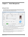
Setting Up Visitors .......................................................................................................................... 36
Visitor Details ................................................................................................................................... 37
Personal Details ............................................................................................................................... 37
Visitor Card Details, Access Rights and Biometrics ................................................................... 37
Visitor Reports ................................................................................................................................. 38
6
Chapter 6: Digital Video Management ................................... 39
Introduction ...................................................................................................................................... 39
Summary of Key Features .............................................................................................................. 39
Using the Virtual Matrix Screen ..................................................................................................... 41
Using the Video Playback Screen .................................................................................................. 42
Identity Verification ......................................................................................................................... 43
Using the Find Button ................................................................................................................. 44
Video Storage Management Module .............................................................................................. 45
Using CCTV Switchers and Cameras ............................................................................................ 46
Viewing a CCTV Image During Alarm Acknowledgement .......................................................... 47
Digital Video and CCTV Switcher Commands .............................................................................. 47
Digital Video Camera Commands............................................................................................... 47
CCTV Switcher Commands ........................................................................................................ 47
Playback from Alarms and Reports ............................................................................................... 48
Graphics Integration ....................................................................................................................... 48
7
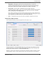
Chapter 7: Alarms Monitoring ................................................ 50
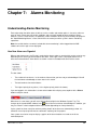
Understanding Alarms Monitoring ................................................................................................ 50
How New Alarms are Signaled ................................................................................................... 50
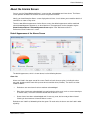
About the Alarms Screen................................................................................................................ 51
Default Appearance of the Alarms Screen ................................................................................. 51
Combined Alarm/Acknowledgement Appearance ...................................................................... 54
Setting Up Alarm Filters .............................................................................................................. 55
Viewing a Graphic of the Alarm's Location ................................................................................. 55
8
Chapter 8: Producing Reports ............................................... 56
Introduction ...................................................................................................................................... 56
Activity Report ................................................................................................................................. 56
ii
SMS Software User Guide
Contents
Reports Available from the Reports Tab ....................................................................................... 57
Examples..................................................................................................................................... 59
Muster (Roll Call) Reports............................................................................................................... 61
Muster Report Configuration ....................................................................................................... 62
Monitoring a Muster .................................................................................................................... 62
Locator Reports ............................................................................................................................... 63
9
Chapter 9: Other Features ..................................................... 64
Setting Up User Roles and Accounts ............................................................................................ 64
Setting Up Roles ......................................................................................................................... 64
Creating User Accounts .............................................................................................................. 65
Sending Commands ........................................................................................................................ 66
Manual Commands (Command Center) ..................................................................................... 67
Scheduled Commands ................................................................................................................ 68
Trigger Commands ..................................................................................................................... 69
Threat Level Management............................................................................................................... 70
Guard Patrol Management .............................................................................................................. 71
Graphics Screen .............................................................................................................................. 71
Creating and Managing Tasks ........................................................................................................ 72
Creating a New Task ................................................................................................................... 73
Completing a Task ...................................................................................................................... 75
Handling Task Alarms ................................................................................................................. 75
Workflow Designer .......................................................................................................................... 75
Triggers and Actions ................................................................................................................... 76
Multiple Workflows ...................................................................................................................... 77
Web Access ...................................................................................................................................... 77
Reader Modes .................................................................................................................................. 77
Card-and-PIN Mode .................................................................................................................... 77
User-Code Mode ......................................................................................................................... 77
Card-Command Mode ................................................................................................................. 78
Keycard Mode ............................................................................................................................. 78
Customer Code Only Mode......................................................................................................... 78
Customer Code Only No Store Mode ......................................................................................... 78
Enabled/Disabled Mode .............................................................................................................. 78
Fingerprint Mode ......................................................................................................................... 79
Duress Mode ............................................................................................................................... 79
Inactivate Card on Pin Error ........................................................................................................ 79
Toggle Mode ............................................................................................................................... 79
Two-Card Mode........................................................................................................................... 79
Reader-Inhibit Mode .................................................................................................................... 79
Antipassback Modes ................................................................................................................... 79
Backing Up and Archiving .............................................................................................................. 80
Multi-Company Installations ........................................................................................................... 80
The Benefits of a Single System ................................................................................................. 80
Company Groups - Keeping Information Private ........................................................................ 80
Device Sharing for Access Rights ............................................................................................... 81
Routing Alarms ............................................................................................................................ 81
10 Appendix A: Underwriters Laboratories (UL) Compliance ..... 82
Code Compliance Requirements ................................................................................................... 82
Card Types ....................................................................................................................................... 82
Modules and Interfaces not Evaluated by UL ............................................................................... 82
11 Index ...................................................................................... 84
SMS Software User Guide
iii
1 Preface
This User's Guide introduces the key concepts of:
•
Symmetry Security Management, including its purpose, scope, main components and architecture.
•
The Symmetry Security Management System software (SMS software), which used to configure,
monitor and control Symmetry Security Management Systems.
This guide is aimed at people who are responsible for day-to-day operation of the Symmetry SMS
software. After reading this guide, you should be reasonably familiar with the purpose and scope of
Symmetry Security Management Systems, how to log in to the SMS software and the key features of the
software. This guide does not attempt to describe the details of each and every option on every screen;
the Online Help is provided for that purpose.
Underwriters Laboratories (UL) Compliance
Please refer to Appendix A on page 82 for information regarding UL requirements, modules and
documents not evaluated, and other UL compliance information.
Other Publications
This guide covers some of the key features of the SMS software. Other publications provide additional
information about optional modules or utilities:
•
Building Control Installation & User Guide
•
813 Fingerprint Reader User's Guide
•
Directory Sync Manager Installation & User Guide
•
Guard Patrol Manager Installation & User Guide
•
Intrusion Management Installation & User Guide
•
M2150 Intrusion Guide
•
Intercom Management Installation & User Guide
•
NIC Module Configuration Guide
•
Web Access Installation & User Guide
•
XML Developer's Kit Installation & User Guide
•
Threat Level Manager Installation & User Guide
•
Data Connect Manual
•
Disconnected Doors Installation and User Guide
•
Digital Video Design Guide
This manual should be read in conjunction with the product help, which is also available in printed form as
the SMS Software Reference Manual.
iv
SMS Software User Guide
1 Chapter 1: Introduction to Symmetry
Security Management
About the Symmetry SMS Software
The Symmetry SMS software (Figure 1-1) allows operators to configure, monitor and control Symmetry
®
®
Security Management Systems. The software runs within the Microsoft Windows operating system on
PCs.
Figure 1-1: Symmetry SMS Software
The SMS software includes an extensive range of standard features, complimented by a comprehensive
range of optional modules that allow an operator to configure, monitor and control the building's security
systems from a common user interface. The software enables you to perform tasks such as to configure
and control access, set up intrusion panels, define guard tours, arm and disarm intrusion areas, design
and print badges, manage visitors, monitor and manage alarms, produce reports, control video cameras,
replay video recordings and operate intercoms. The SMS software provides a framework that allows all of
these different areas of site security to come together as a single solution.
SMS Software User Guide
1
Introduction to Symmetry Security Management
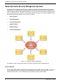
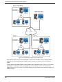
About Symmetry Security Management Systems
A Symmetry Security Management System is a powerful integrated solution for organizations requiring
automated security. Symmetry Security Management consists of the core SMS software, together with a
range of software modules and hardware devices that can be selected to match the security requirements
of the site. Depending on the modules and hardware selected, the system can provide integrated control
and monitoring of all key elements of site security, including:
•
Access Control
•
Video Management
•
Intrusion Management
•
Guard Patrolling
•
Building Control
•
Intercom Management
Figure 1-2: Symmetry Security Management
The following sections explain each of the key elements of Symmetry Security Management.
Access Control
The Symmetry SMS software, supported by the Symmetry range of nodes and card readers, can control
access through all forms of entrance, including standard doors, turnstiles and revolving doors. Access
control for elevator floors is also available using the Symmetry range of elevator nodes.
2
SMS Software User Guide
Introduction to Symmetry Security Management
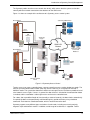
The Symmetry nodes store the access control rules locally, which means that the system can function
normally without a network connection to the database on the SMS server.
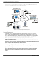
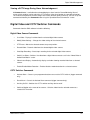
Figure 1-3 shows an example of the architecture of a Symmetry access-control system.
Door Monitor
Symmetry SMS Clients
Door
Release
Exit
Request
Symmetry
Nodes
WAN/LAN
Network
Reader
Symmetry SMS
Server and
Database
Door Monitor
Door
Release
Monitor
Points
Reader
Elevator Control
Panel
Auxiliary
Outputs
Figure 1-3: Symmetry Access Control
To gain access to an access-controlled area, a person normally presents a card or badge to a reader. The
entry of a personal identification number (PIN) may also be necessary, or a fingerprint or hand for a
biometric reader. The system then determines whether or not to grant access based on a predefined set of
rules known as access rights. If access is granted, the door release is activated or the elevator floor button
is enabled, and the card holder is able to gain access to the access-controlled area.
For a door, after a predefined length of time (normally a matter of seconds), the door relocks automatically.
If required, the door can be permanently unlocked during busy periods of the day using scheduled
commands. Each door has a dedicated reader, which is located close to the door.
Symmetry supports many different types and makes of card reader, including smart-card, proximity,
magnetic stripe and biometric readers. In addition, a wide range of card formats is supported. Further
SMS Software User Guide
3
Introduction to Symmetry Security Management
information about Symmetry readers and the card formats supported can be found in the Symmetry reader
data sheets.
Each door also has a door-monitor contact. This detects when the door has been opened or closed, and
enables the system to determine whether, for example, the door has been forced or kept open too long.
In some cases, a door also has an exit-request switch, which when pressed, activates the door release.
The exit-request switch is normally located next to a final exit to allow people free access to leave the
building.
An access-control card contains a unique number that identifies the card holder to the system, and
therefore the access rights of the card holder. The access rights, which can be set up in the SMS software,
specify which doors or floors the card holder is allowed to use and at what times. Not only can the access
rights vary from day to day, but also for specified holidays, which maintains the security of your building
during vacation periods, shutdown periods or any other nominated days.
Symmetry SMS Client and Server Machines
The SMS server, which should never be switched off, is the PC that holds and manages the Security
Management System's databases. All data about the Security Management System, including card
holders, access rights and alarms is stored in the server's databases. The server also performs various
management functions, such as to process transactions made at access-control readers, start trigger or
scheduled commands across nodes and initiate scheduled reports.
The client PCs connect to the server over a network. Clients provide the user interface to the SMS
software. They enable you to carry out tasks such as to set up card holders, specify access rights, print
badges, view alarms, produce reports, and monitor, record or play back video images. They also control
communications to the security management hardware located around the building, such as the nodes
that operate the doors and readers. The SMS client software is installed by default on the server.
There can be many clients in use simultaneously, up to a limit determined by the system purchased. The
number of clients required depends on the number of nodes and other security management hardware in
use, and the number of users who need to use the SMS software. In a large system, many clients may be
required, each for a different purpose. Each user of the SMS software has a set of login privileges, which
determine the range of screens that are available and the functions that can be carried out.
Alarms can be sent to any of the clients according to the time of day, day of the week or even on holiday
dates. This allows, for example, alarms to be displayed on an operator's PC during the day, then on the
guard's PC during the night.
Each SMS client can support up to 512 LAN chains and/or 16 dial-up/serial hardwired chains.
About Symmetry Nodes
The Symmetry nodes provide distributed intelligence for the Security Management System. Using a copy
of the relevant rules that have been set up on the client PCs, nodes manage all their connected devices,
including readers, door releases, monitor points and auxiliary outputs. A node can independently decide
whether or not to grant access, and can respond in the desired manner to any attempted access violation.
Alarm messages are immediately sent to a client PC for the attention of the guard or alarm reporting.
A Symmetry node consists of a database unit, and one or more door controllers. The database unit holds
the access-control rules, while the door controllers provide the physical connections to the door furniture.
Symmetry provides a range of integrated database units and controllers on the same PCB, and separate
devices that can be mounted in different locations for ease of installation.
There are several ranges of Symmetry hardware available. The most recent is the M2150 range, which
supports up to 16 readers controlled by a single node. The system can be easily expanded by connecting
4
SMS Software User Guide
Introduction to Symmetry Security Management
additional nodes, either directly to the network, or from a node that is already connected to the network. In
the latter case, no addition IP addresses are required for the additional nodes. Symmetry also supports
connection of nodes using a serial links to client PCs.
For further information about node types and hardware configurations, please refer to the M2150 Design
Guide.
About Monitor Points and Auxiliary Outputs
The Symmetry hardware allows connection of monitor points and auxiliary outputs. Monitor points are
devices such as infra-red detectors, floor pads, door contacts or other sensors. They are constantly
monitored, and if triggered, cause the node to generate a predetermined response, such as displaying an
alarm at a client PC or recording video.
Auxiliary outputs are devices such as external lights, sirens and barriers that can be switched on or off (or
switched on for a predefined period of time), either by a manual command from a client PC or
automatically by a scheduled or trigger command. For example, a scheduled command may switch on an
outside light at specific times of the day, and a trigger command may cause a device to operate
automatically when an event or alarm occurs. Trigger commands are a very powerful feature, which
provide extreme flexibility without the overhead of complexity.
Both auxiliary outputs and monitor points can connect to an input/output module fitted to a node, to an
alarms controller or to an output controller. The M2150 AC24/4 alarms controller supports up to 24 monitor
points and four auxiliary outputs. The M2150 OC4/24 output controller supports up to four monitor points
and 24 auxiliary outputs.
About Alarms and Events
The system constantly monitors all activity at devices such as readers, doors, monitor points and video
cameras, and logs all major actions that take place. The SMS software can log when access is granted,
when doors are closed, when movement is detected and more serious conditions, such as when a door is
forced or when a lost card has been used. Each of these conditions is classed as an alarm or event,
depending on importance, with alarms being the most important.
Details of all alarms can be monitored in real time at a PC and are also logged for future reporting. Events
are simply logged for reporting. If required, alarms can also be directed to maintenance or security
personnel by email.
For further details of alarms monitoring, please refer to Chapter 7.
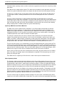
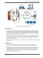
Video Management
The Symmetry Video Management module of the SMS software provides all the interfaces and tools
necessary to monitor, record, play back and control cameras from computers located anywhere on the
network. Symmetry supports a wide range of network cameras, Digital Video Recorders (DVRs) and
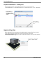
Network Video Recorders (NVRs), including Symmetry's own brand of devices (Figure 1-4).
Symmetry also supports interfaces to legacy analog CCTV switchers, which facilitates an easy upgrade
from an analog to digital solution. Cameras attached to legacy CCTV switchers can be viewed, controlled
and switched to any monitor, and ancillary devices (such as lamps and wipers) can be switched on or off
from the SMS software user interface.
The SMS software allows video systems to be deeply integrated with access control, intrusion and other
parts of the Symmetry Security Management System.
SMS Software User Guide
5
Introduction to Symmetry Security Management
Chapter 6 explains Video Management in more detail. The Digital Video Design Guide also provides
information on how to approach the design of digital video systems.
Symmetry Database and
Network Video Recorder (NVR)
Network (IP)
Cameras
Symmetry Client (e.g. for
video monitoring)
Digital or Network Video
Recorder (DVR/NVR)
WAN/LAN
Network
CCTV Switcher
Monitors
Analog cameras
Network Attached
Storage (NAS)
Figure 1-4: Symmetry Digital Video Management
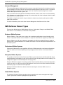
Intrusion Management
The Symmetry Intrusion Management module allows Symmetry M2150 intrusion panels, third-party
intrusion systems to be monitored, controlled and configured from the SMS software (Figure 1-5). The
Intrusion Management module provides complete alarms monitoring and reporting from the same SMS
software user interface used by other parts of the Security Management System. The module also
supports alarm monitoring from Bosch D6600 Central Station communications receivers.
Note the Third Party Intrusion systems and the Bosch D6600 Receiver not evaluated by UL for use with
the SMS Symmetry M2150 Panels)..
Operators can arm or disarm areas, enable or disable detectors and determine the status of all parts of the
intrusion system using the Command Center in the SMS software.
The Intrusion Management module also allows intrusion systems to interact with other modules of the
Security Management System. For example, an intrusion alarm can automatically start a video recording
at a selected camera, and an access-control transaction can automatically disarm an intrusion area
depending on access rights.
Intrusion Management is explained in further detail in two publications: the M2150 Intrusion Guide (for
M2150 systems) and the Intrusion Management Installation and User Guide (for all other intrusion
systems).
6
SMS Software User Guide
Introduction to Symmetry Security Management
Symmetry Server
and Clients
Integration with
Access Control
Integration with
Digital Video
WAN/LAN
Network
Third-party
Intrusion Systems
M2150 Intrusion
Remote Central Station
Figure 1-5: Symmetry Intrusion Management
Guard Patrolling
The Guard Patrol Manager is an optional module for configuring, recording and reviewing guard patrols.
The module includes a complete set of tools for setting up and managing patrols entirely from the SMS
software. It benefits from the ability to use access-control readers or monitor points as tour checkpoints,
resulting in the need for no specialist hardware or data-collection devices, and making the introduction of
patrol management both cost effective and easy to implement.
Patrols can be set up to specify the sequence of checkpoints to visit and the time allowed for the guard to
travel between them. The progress of a patrol can be monitored, and previous patrols reviewed in reports.
The SMS software can display any rule infringements, such as missed checkpoints or late arrival,
immediately in the Alarms screen.
For further details of Guard patrolling, please see page 71 or refer to the Guard Patrol Manager Installation
and User Guide.
Building Control
The Building Control module of the SMS software provides automatic control of third-party building
systems, such as lighting equipment or Heating, Ventilation and Air Conditioning (HVAC) units.
By monitoring activity at access-control readers and by using movement sensors, the SMS software is
able to judge whether an area is currently occupied or unoccupied. This generates an on/off status value
for a building control defined from the SMS user interface, which can be used by third-party building
systems to switch devices such as HVAC units on or off. For further information, please refer to the
Building Control Installation and User Guide.
SMS Software User Guide
7
Introduction to Symmetry Security Management
Intercom Management
The Intercom Management module provides an easy-to-use graphical interface for managing, answering
and responding to calls from intercoms connected to Stentofon Alphacom intercom systems. The module
enables operators to respond to calls using the same user interface used to manage access control,
monitor video, operate intrusion systems, etc.
Calls are answered and managed from the dedicated Intercom Control screen, which lists all outstanding
calls. Operators can use the screen to manage calls, communicate with callers and open a barrier or door
associated with a selected intercom.
The module is of particular benefit in busy environments, where many incoming call requests could be
made at the same time.
For further information, please refer to the Intercom Management Installation and User Guide.
SMS Software Product Types
There are four different types of SMS Software: Business, Professional, Enterprise and Global Edition.
Each of these is also available as a Homeland Security Edition.
Business Edition Systems
Business Edition is a true client/server system, with a maximum configuration of up to 64 readers and 3
clients. If required all software can be installed on a single PC. Each node can support up to 2000 cards.
Business Edition uses SQL Server databases managed by the SQL Server 2008 R2 Express database
engine. With its maximum database size of 10GB, SQL Express has been designed and optimized for use
on smaller systems.
Professional Edition Systems
Professional Edition builds on the capabilities of Business Edition to provide a maximum configuration of
up to 512 readers and 9 clients depending on the package purchased, with an unrestricted number of
cards.
Enterprise Edition Systems
This provides all the features of the Professional Edition system, but utilizes the full Microsoft SQL Server
relational database management system, which meets the needs of high performance and scalability. This
configuration supports unrestricted expansion for large systems.
Enterprise Edition also supports "clustering" (see the Cluster Installation Manual), where two independent
servers are seen as a single server by the SMS software. If one server in the cluster should fail, the other
automatically steps in to continue normal operation.
Although installed, the SMS client software should not normally be used on an SMS server in an
Enterprise system.
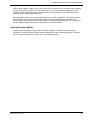
Global Edition Systems
This builds on Enterprise Edition to provide enhanced capabilities for remote management of multiple
systems spread over a number of geographically separate sites.
8
SMS Software User Guide
Introduction to Symmetry Security Management
Global Edition supports "Global Clients" (see Figure 1-6). Each Global Client can connect to any regional
system and log on as if it were a local client of that site. This gives true remote management of sites,
allowing full access (dependent upon user permissions) for history reporting, card administration and
control of readers, doors and monitor points.
Optionally, Global Clients can also be provided with alarms-handling capabilities. This allows the head
office or regions to communicate alarms to the Global Client for centralized alarm notification and
management. Alarms can be routed to Global Clients at specified periods of the day, such as during outof-hours periods. Global Clients have no attached access-control hardware.
Homeland Security Edition
A Homeland Security Edition (HSE) variant of the SMS software is available for US Government
installations. Homeland Security Edition includes additional fields when defining card details. Otherwise,
the user interface and features are the same as the standard software.
SMS Software User Guide
9
Introduction to Symmetry Security Management
Region 0 (Head Office)
Server (holds
local databases)
Global Client (able to
connect to any region)
LAN
Networked Clients
WAN
Region 1
Region 2
Server (holds
local databases)
Server (holds
local databases)
LAN
Networked Clients
LAN
Networked Clients
Figure 1-6: Global Edition System, with Global Clients
Each region must be set up in the Install/Regions screen at the head office. Access-control and other
equipment can be connected to each regional system in exactly the same way as for an Enterprise
system.
A further option of the Global Edition system provides central card handling (see Figure 1-7). This allows
card holders to be defined centrally, assigned to one or more regional systems, then automatically
imported to each site. The Central Card Handler database can be located on the head office server or on
another machine.
10
SMS Software User Guide
Introduction to Symmetry Security Management
Region 0 (Head Office)
Server (holds
local databases)
LAN
Networked Clients
Central Card
Handler Client
WAN
Region 1
Region 2
Server (holds
local databases)
Server (holds
local databases)
LAN
Networked Clients
LAN
Networked Clients
Figure 1-7: Example Global Edition System, with Central Card Handling
Central card handling not only provides a multi-site organization with the improved efficiency of central
card management, but also provides the ideal solution when persons require access to more than one
site, as one operation will add cards at all the required locations.
Global Edition architecture provides the ultimate resilience for multi-site applications, since any failure of
the corporate network links still allows autonomous regional systems to continue operating fully at a local
level.
SMS Software User Guide
11
Introduction to Symmetry Security Management
Summary of Client Types for Global Systems
The following client types are available for Global Systems:
•
Central Card Handler Client - Allows a central database of card holders to be maintained and
imported by the individual regional systems. There can be more than one Central Card Handler
client.
•
Global Client - A client that can connect to any regional system and log on as if it were a local client
of that site for true remote management of sites.
•
Global Client + Alarm Handler - Enables a Global Client to display alarms routed from regional
systems and to connect to the regional systems for alarm acknowledgment and remote
management of sites.
•
Administration Client - A standard client for monitoring and setting up the system (see page 4).
Although installed, the SMS client software should not normally be used on an SMS server in a
Global system.
Summary of Features
Standard Features
Standard features of the SMS Software include:
•
Easy-to-use and up-to-date user interface
•
Full integration with all Symmetry security products and many other third-party systems
•
Complete control of access rights (to specify "who" is allowed to go "where" and "when")
•
Easy card administration, including bulk amendments
•
Dynamic alarms management
•
Graphics interface (e.g. to display alarms on plans of the building)
•
Badge designing and printing
•
Database partitioning
•
Login permissions control user access to screens and the menu options displayed
•
Extensive reporting options
•
Commands
•
Visitor management
•
Antipassback management
•
Area occupancy management
•
Straightforward control of hardware using manual and automated commands
•
Comprehensive context-sensitive online help system
•
Dial in and Dial-Out Alarms (not evaluated by UL)
Email Alarms (not evaluated by UL)
12
SMS Software User Guide
Introduction to Symmetry Security Management
Optional Features
Optional features of the SMS software include:
•
Integration with digital video cameras, digital video recorders, network video recorders and CCTV
systems
•
Integration with intrusion systems, including the Symmetry M2150 intrusion system
•
Optional video-only product
•
Integration with SALTO™ online/offline readers (not evaluated by UL)
•
Magnetic Stripe and Smart Card Encoding
•
Threat Level Management
•
XML Developer's Kit
•
Building Control (BACnet ) interface
•
Intercom Control Integration
•
Card Data Import and Card Data Export
•
Guard Patrols
•
Safety Roll Call Management (mustering) (not evaluated by UL)
•
Web access
®
SMS Software User Guide
13
2 Chapter 2:
Getting Started
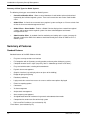
Starting the SMS Software
To start the SMS software:
1.
Double-click the following icon on the Windows desktop:
Alternatively, select Start/All Programs/Security Management System/Security Management
System.
2.
You are now prompted to log in:
3.
Enter your allocated user name and password to gain access to the screens of the SMS software.
Your login user name determines the screens that are made available to you, and your user
permissions within the screens. For example, you may have full permissions to change information
in some screens, but view-only permissions in others. Details of how to set up users and their
permissions are given on page 64.
Once you have logged in, you can change your password by using the "Maintenance/User &
Preferences/Set Password" screen.
SMS Software User Guide
14
Getting Started
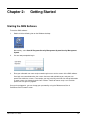
About the User Interface
After a successful login, the Security Management window is displayed, with a ribbon bar and options
shown at the top of the window, as shown in Figure 2-1.
Selecting an option
displays a screen in the
main area of the window.
The ribbon bar gives
quick access to
options.
These display your
login name and
company name.
These show the number of unacknowledged
alarms, the number of uncleared alarms, the
number of unacknowledged task alarms, and
the priority of highest-priority alarm.
Figure 2-1: SMS Software Main Window
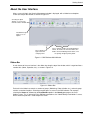
Ribbon Bar
A main feature of the user interface is the ribbon bar along the top of the window, which is organized into a
number tabs (Home, Operation, etc.), as shown in Figure 2-2.
Figure 2-2: Ribbon Bar
Each tab in the ribbon bar contains a number of groups (Monitoring, Video & Audio, etc.), and each group
contains a number of options. Selecting an option opens a screen in the SMS software. For example,
selecting the Home tab, followed by the Card Holders option in the Identity group opens the Card
Holders screen. This is referred to in the SMS documentation as the "Home/Identity/Card Holders" screen,
which shows the path that is used to open the screen.
SMS Software User Guide
15
Getting Started
Quick Access Toolbar
If required, you can set up a Quick Access Toolbar, which can contain options to access your favorite
screens. Bt default, the toolbar is located near the top-left corner of the window, as shown in Figure 2-3.
You can add and remove icons from the toolbar using the More Commands option selected from the
menu to the right of the toolbar.
Quick Access Toolbar
More Commands
option
Figure 2-3: Quick Access Toolbar
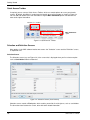
Selection and Definition Screens
Many options in the SMS software lead to two screens: the "Selection" screen and the "Definition" screen,
as explained next.
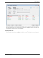
Selection Screen
The Selection screen (e.g. see Figure 2-4) is the screen that is displayed when you first select an option
such as Card Holders from the ribbon bar.
Figure 2-4: Selection Screen (Card Holders)
Selection screens contain a Find option, which enables you to find all existing items, such as card holders.
The items found are listed on the screen, often with other related information.
16
SMS Software User Guide
Getting Started
If you want to be selective about the items to list, you can choose the filter options in the upper area of the
screen. Selecting Find then displays only those items that match the filter settings.
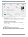
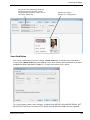
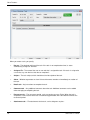
Definition Screen
Selecting New in the Selection screen, or selecting one of the items listed in the Selection screen followed
by Open, displays the Definition screen, such as the Card Holder Definition screen, as shown in Figure
2-5.
Figure 2-5: Definition Screen (Card Holders)
Using the Definition screen, you can perform tasks such as to:
•
View or modify the details of the selected item. Note: you are given view-only access if another
person on the network is already viewing or modifying the item.
•
Define a new item, such as to set up a new card holder.
•
Delete the item entirely from the system.
•
Copy the item's details to create a new item.
Online Help
Every screen in the SMS software contains a Help button. Clicking the Help button provides
comprehensive context-sensitive help for that screen.
SMS Software User Guide
17
Getting Started
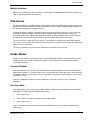
Logging Off
You can log off from the SMS software by selecting the SMS button in the top-left corner of the screen,
followed by Logoff, as shown in Figure 2-6.
Figure 2-6: Logoff
Note that the system may automatically log you out if you have not used the computer for a predefined
period of time (default 15 minutes). You can change this using the Auto Logoff Time option in the
"Maintenance/User & Preferences/Client Preferences" screen.
What you need to do next
Before you start to use the SMS software, you need to make sure your system's hardware has been
configured correctly using the Install screens. This User's Guide assumes that these tasks have been
completed for you by an installer, and includes setting up:
•
The SMS client PCs that are being used.
•
The LAN chains that the SMS hardware connects to.
•
The node chains.
•
The nodes, readers, monitor points, CCTV cameras, video servers, etc. used in your system.
Once these tasks are complete, you can work through this User's Guide to learn more about the SMS
software. You will find out how to:
•
Set up card holders and access rights – Chapter 3.
•
Design, print and encode ID badges (or cards for access control) – Chapter 4.
•
Use the system for visitor management – Chapter 5.
•
Use and control CCTV cameras and digital video systems – Chapter 6.
•
Set up and use the alarms-monitoring features – Chapter 7.
•
Set up and generate reports – Chapter 8.
•
Use other important features – Chapter 9.
Other optional modules are described in separate manuals; see page iv.
18
SMS Software User Guide
3 Chapter 3:
Card Administration
This chapter describes how to set up card holders and define access rights.
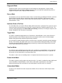
About the Card Holders Screen
The "Home/Identity/Card Holders" screen is where you set up the details of each person who requires an
access-control card or identity badge (except visitors, who are set up in the "Home/Identity/Visitors"
screen). Using the Card Holders screen, you can perform tasks such as to:
•
Enter the details of the card holder, such as the card holder's name, card number and personal
details.
•
Specify the card holder's access rights. For example, the doors through which the card holder can
gain access, and the times that access can be gained.
•
Capture a photograph and signature to include on the printed badge.
•
Print and encode cards.
•
Capture biometric data, such as fingerprints, which can be encoded onto smart cards for access at
high-security fingerprint readers.
Finding or Creating a Card Holder
After opening the "Home/Identity/Card Holders" screen, use the Selection screen to open an existing card
holder, or click New to create a new card holder. This displays the Definition screen. In the following
example, the existing card details for Alex Taylor have been opened.
19
SMS Software User Guide
Card Administration
The Card Holder Definition screen contains a series of tabs:
•
Card Details tab – Allows you to capture the card holder's picture and to set up information such as
the dates that the card is valid, the badge design and any special privileges that you want to assign
to the card. See Setting Up Card Details on page 21.
•
Access Rights tab – Specifies the doors through which the card holder is allowed to gain access.
See Creating and Assigning Access Rights on page 23.
•
Personal tab – Allows you to specify personal information about card holder. See Specifying
Personal Data on page 29.
•
Locator tab – For finding the card holder's current location. See Locating a Card Holder on page
29.
•
Biometrics tab – Enables you to capture biometric data, such as the card holder's fingerprints and
signature. See page 33.
You may not have access to some tabs, depending on your user permissions.
Note: The following sections describe the key features of the Card Holders screen. If you need further
information, please refer to the Online Help.
20
SMS Software User Guide
Card Administration
Last Name, First Name and Middle Name
Each card holder must have their name specified in Last Name, First Name and Middle Name.
If possible, you should make sure that these three fields make the card holder's name unique, otherwise
you may find reports, etc. confusing if two people have the same name.
Card Number
The Card Number should normally be unique. If the card is used for access control, the card number must
correspond to the number on the card issued to the card holder.
If you leave the Card Number field empty when defining the details of a new card holder, a card number is
allocated automatically when you select Save, providing Auto Card Number is selected in the
"Maintenance/User & Preferences/System Preferences" screen. If Auto Card Number is not selected, a
card number of zero is used (you can enter the correct card number at a later date).
If you are using magnetic stripe cards and have an appropriate encoding unit, you can encode the card
number onto the card using the "Maintenance/Access Control/Encode Cards" screen or when printing the
badge. If you are using smart cards, you can use a Smart Card button in the Card Holders screen to
encode the card.
Setting Up Card Details
This section describes key features of the Card Details tab in the Card Holders screen:
SMS Software User Guide
21
Card Administration
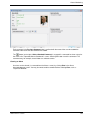
Card Holder's Picture
If this large icon is displayed on the right of the Card Details tab, it indicates that the card
holder's picture has not yet been captured. A picture may be required for the card holder's
badge (see page 33). Once captured, the actual picture of the card holder replaces the
icon.
The tab provides two alternative methods to capture the person's picture:
•
Live – Click this to capture a live picture of the card holder's from a camera connected
to your PC.
•
Import – Click this to import a stored picture of the card holder (e.g. taken by a digital
camera).
Active and Inactive Dates
Use the Active Date and Inactive Date to specify the period over which the card can be used to gain
access (the doors and times that the card can be used are defined in the Access Rights tab). A card
cannot be used as from midnight on its Inactive Date, irrespective of access rights.
PIN Code
The PIN Code option enables you to specify a PIN (Personal Identification Number) for the card holder.
This is essential for any card holder who will be using card-and-PIN readers, since access cannot be
granted until the card holder presents the card and enters the correct PIN.
By using commands (see page 66), you can switch any reader between card-only and card-and-PIN
modes at any time. When a reader is in card-only mode, a PIN does not have to be entered, which may be
appropriate at busy times of the day.
A card holder can also use the PIN to create a "duress" alarm/event by preceding the PIN with a zero and
not entering the last digit. The alarm/event signals that the card holder is gaining access under duress.
Duress mode can be switched on or off for each reader.
Facility/Customer Code
Some cards include a customer code (otherwise known as a facility code), which identifies the card
holder's company. You need to choose the code from the Facility/Customer Code menu. The codes in
the menu are defined in the "Setup/Configuration/Facility/Customer Codes" screen.
Badge Design and Badge Expires
You can use the Badge Design menu to choose the badge design for the card holder (see page 34).
If the badge design has an expiry period, the expiry date is displayed in Badge Expires. If the badge is
used as an access-control card, it will not be able to be used to gain access after this date.
22
SMS Software User Guide
Card Administration
Additional Card Options
You can use the checkboxes in the Additional Options area to specify additional privileges for the card
holder. For example:
•
Executive Card – An executive need not enter a PIN at readers in card-and-PIN mode.
•
Extended Door Times – This is useful for card holders who are disabled, or for another reason
require more time than is normally necessary to open and get through a door. If you select the
option, the system uses the extended door times (as set up in the "Maintenance/Access
Control/Door Timing" screen) each time the card holder gains access.
•
Command Card Holder – This enables the card holder to generate card command messages at
keypad readers. The messages can be made use of by trigger commands, for example to arm or
disarm intruder alarm systems or to switch lights on or off. Card commands can also be used by
users to change their PIN or the door open time.
Card Status
The Card Status area displays and enables you to change the current status of a card. For example,
selecting Card Lost, as it implies, is useful if the card has been lost or stolen, since if the card is used, the
"Lost Card" alarm/event is generated and access is not granted.
Active is the normal status for a card and enables the card to be used normally.
An Expired status can be set automatically if the card remains unused for a specified period of time
(perhaps because the card holder no longer works for your company). The time period can be specified in
the "Maintenance/User & Preferences/System Preferences" screen.
Creating and Assigning Access Rights
A card holder's access rights, which can be specified in the Access Rights tab of the Card Holders screen,
determine which parts of the building he or she has access to and at what times. For example:
SMS Software User Guide
23
Card Administration
The card holder's Assigned Access Rights can comprise Normal Rights and Advanced Rights, displayed in
a graphical tree view. You can expand the branches of the tree to view their contents in the normal way.
Normal rights are the standard access rights assigned to the card holder. The top level of this branch is
always displayed in the tree view.
Advanced rights are used to replace the normal access rights between specified dates. For example, if the
card holder has temporary duties in a different office or building, advanced rights can be used to assign
the new access rights for the relevant dates. If the Advanced Rights branch is not displayed, click Show
All to display it.
You can assign access rights by, for example, clicking Readers, followed by Assign. In this case, the
Assign Reader dialog is displayed:
In the Assign Reader dialog, you choose one or more readers that the card holder is allowed to access
from the list in the top-left corner. You also need to choose a time code (described in the next section),
which restricts access to the reader to specified times of the day. In the previous example, the area on the
right shows that "Entrance 1 Reader" has been selected with the "Normal Office Hours" time code. The
graphic in the bottom-left corner shows that the time code has been specified as 08:00 to 18:00 Monday to
Friday, which restricts the use of "Entrance 1 Reader" to those times.
In addition to readers, the Access Rights tab allows other types of access rights to be set up. For example:
•
Reader groups – A reader group is a group of one or more card readers, as set up in the
"Setup/Device Groups/Readers" screen. Reader groups allow access to a group of readers to be
assigned quickly and easily.
Normally, employees who work in the same office require the use of the same readers, so defining
reader groups reduces the amount of work involved in setting up employee access rights.
24
SMS Software User Guide
Card Administration
•
Floor groups – A floor group is a group of one or more elevator floors, as set up in the
"Setup/Device Groups/Floor/Output" screen. You will need to use them if you want to restrict the
floors that can be selected on an elevator's control panel. For example, some employees may
require access to floors 1 to 10, but others may require access to floors 1 and 2 only.
•
Access codes – An access code is a predefined set of access rights set up in the
"Operation/Times/Access Codes" screen. An access code can define a collection of access rights to
readers, reader groups and floor groups. By using access codes, you can assign a card holder
access to all these items in one simple operation.
Access codes are particularly useful if you need to assign the same access rights to more than one
person. For example, you could set up an access code called "Admin Staff" containing all the access
rights needed by the card holders working in the Administration department.
•
Areas – This determines the intrusion areas that the card holder is allowed to arm or disarm.
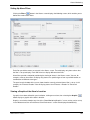
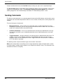
Defining Time Codes and Hours
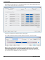
You can define time codes by using the "Operation/Times/Time Codes" screen:
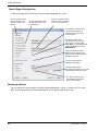
Using the pull-down lists in the Standard Weekly Hours tab, you choose the "hours definition" to use for
each day of the week. In the previous example, "08:00-18:00 Access Right" has been selected for each
week day, which indicates that access is allowed from 08:00 to 18:00.
By default, a number of hours definitions are automatically installed during software installation, including
"08:00-18:00 Access Right ". An hours definition contains one or more time intervals, which determine
SMS Software User Guide
25
Card Administration
when people will be able to gain access. In the following example, the hours definition "08:00-18:00 Except
Lunch" has been selected, which consists of two intervals:
There can be a maximum of ten different time intervals per time code.
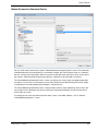
You can add or modify hours definitions using the "Operation/Times/Hours" screen. For example:
Note: Time codes (and therefore hours definitions) are used when setting up access rights, scheduled
commands and trigger commands. You can use the Category pull-down menu shown in the top-right
corner of the Hours Definition and Time Code Definition screen to restrict the item's use. For example,
selecting Access Right enables the time code or hours definition to be used only when setting up access
rights. The default setting is General, which allows unrestricted use.
26
SMS Software User Guide
Card Administration
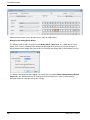
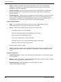
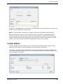
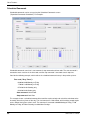
Defining Holidays
By using the "Operation/Times/Holiday" screen, you can set up holiday dates, which gives you the
capability of having different access times for holiday periods.
In the Holiday screen, you first name the holiday types in the boxes near the bottom of the screen (e.g.
"Public Holiday" and "Christmas Shutdown"). You then select one or more dates, click Assign and choose
the holiday types to assign to the selected dates:
Once you have used the Holiday screen to define the holiday dates, you can use the Holiday Hours tab in
the "Operation/Times/Time Codes" screen to specify the hours to use for each holiday type. In the
following example for the "Normal Office Hours" time code, "No Hours" is selected for the "Christmas
Shutdown" holiday type and "Half Day" for the "Half Day" holiday type (e.g. Christmas Eve).
SMS Software User Guide
27
Card Administration
Defining holidays makes it easy to adjust access rights for holiday dates.
Displaying the Holiday Check Dialog
The Holiday screen includes an option named Holiday Check 7 days Prior. It is a good idea to set this
option, since it causes a Holiday Check dialog to be displayed when you log in at any time during the 7day period prior to the holiday date (so that you can check that the holiday date is correct before it occurs):
The dialog is displayed only when logging in at the machine specified by Route Holiday/Advance/Retard
Checks to in the "Maintenance/User & Preferences/System Preferences" screen (a similar dialog is
displayed to warn of a daylight-savings time change).
28
SMS Software User Guide
Card Administration
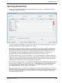
Specifying Personal Data
You can use the Personal tab of the "Home/Identity/Card Holders" screen, as shown below, to specify
personal data about the card holder.
The personal data titles displayed in this tab (such as "Job Title", "Hair Color" and "Gender") are set up in
the "Setup/Identity/Personal Data/Card Holder Titles" screen.
A pull-down list may be displayed for some personal data titles. These are for common information such
as "Hair Color", "Gender", etc. For these titles, you can choose predefined data from the pull-down lists.
Depending on how the titles are set up in the "Setup/Identity/Personal Data/Card Holder Titles" screen,
you may be able to type text directly into the empty first box of the pull-down list. In this case, the
information you type is automatically added to the list the next time you use the screen.
The personal data titles that do not have pull-down lists are for information that is likely to be different for
each person, such as "Date of Birth". For these, you simply type the text directly into the box. If a "Mask" is
set up in the "Setup/Identity/Personal Data/Card Holder Titles" screen, you may be required to enter the
information in a particular format, such as mm/dd/yyyy for a date value.
Specifying personal data provides useful additional information about the card holder that may be required
from time to time. In addition, it also enables you to use the Card Data Title and Visitor Data Title filters
in the Card Holder/Visitor Selection screen. These filters can be used to find a person's name from
specified personal data, such as a vehicle license number.
Depending on how the titles are set up in the "Setup/Identity/Personal Data/Card Holder Titles" screen, it
may be mandatory to specify data for some or all of the titles. These have a red marker on the right-hand
side. If there are mandatory fields, you will not be able to save the card holder's details until you have
specified personal data in them.
SMS Software User Guide
29
Card Administration
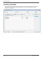
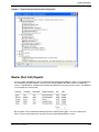
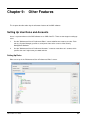
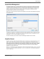
Locating a Card Holder
On occasions, you may want to determine a card holder's current location in a building. You can use the
Locator tab of the Card Holders screen for this purpose, which lists the card holder's last 25 reader
transactions. For example:
30
SMS Software User Guide
4 Chapter 4:
Producing ID Badges
Introduction
The Security Management Software provides a
comprehensive set of tools that allow you to design and
print ID badges quickly and easily. A badge may be used
for identification purposes only, or for access control, or
both.
Producing ID badges is easy. First, you use the
"Setup/Identity/Badge Designer" screen to create a library
of badge designs, then the "Home/Identity/Card Holders"
screen to select, print and encode a badge for each
person.
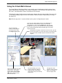
Using the "Home/Identity/Card Holders" screen, you can quickly enter any information that is required for
the badge, such as the card holder's name and card number. You can also capture the person's picture,
signature and any biometric data, then print and encode the card. The user interface has been designed to
optimize operator efficiency, while allowing full control to include all the graphics and information required.
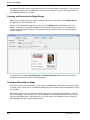
Designing Badges
You can design badges using the "Setup/Identity/Badge Designer" screen. A badge design specifies the
appearance of the badge, including the position and type of information to include. For example, a badge
design could include the card holder's name, expiry date, company logo and card holder's picture. The
system gives you all the tools you need to create customized badge designs in minutes, with text and
graphics applied to both sides of the badge.
Using the Badge Designer, you can create a library of badge designs. You may, for example, decide to
create different designs for administration staff, cleaners, contractors and security staff.
A key feature of the Badge Designer is the ability to associate default access rights with each badge
design for access control purposes. Any card holder allocated a badge design is automatically given the
badge access rights, which eliminates the need to set up access rights for each person.
The overall simplicity of the software, supported by context-sensitive help, ensures that anyone with basic
mouse/keyboard skills can begin to use the Badge Designer quickly and efficiently.
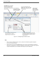
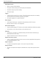
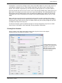
Figure 4.1 gives an overview of the key features provided by the Badge Designer.
31
SMS Software User Guide
Producing ID Badges
Card Data allows you to define
the position of text that varies
for each card holder, such as
the card holder's name or card You can specify an
expiry period. A badge
expiry date.
cannot be used to gain
access once expired.
You can use the options in the
Tools group to draw or place down
objects, such as shapes, text and
a company logo.
You can use this
option to toggle
between designing
side 1 and side 2 of
the badge.
You can associate
default access rights
with the badge.
You can right-click in white space and
specify the position of a chip or
magnetic stripe on the current side.
You can define the position and size of the
card holder's signature and picture, then use
the "Home/Identity/Card Holders" screen to
capture this data.
Figure 4-1: The Badge Designer Definition Screen
Note:
32
•
When you open the Badge Designer screen, a new tab in the ribbon bar provides the options
necessary for designing badges.
•
Right-clicking an item and selecting Rule enables you to set up a rule that determines whether or
not the item is displayed for a card holder, depending on personal data. For example, you may want
a logo to be displayed only for card holders who belong to a specific department.
SMS Software User Guide
Producing ID Badges
Producing a Card Holder's Badge
Once you have produced the badge designs, you can select each card holder's badge from the
"Home/Identity/Card Holders" screen, as described next.
Entering Card Details and Capturing the Card Holder's Picture
First, you need to make sure that the card holder's details are correct, and to ensure that the card holder's
picture has been captured (assuming that a picture is to be printed on the badge). Use the Card Details
tab to do this, as described on page 21.
Approving Official
The Card Details tab includes an Approving Official option. You can use this to choose the name of the
person who has authorized the badge to be issued. You can set up approving officials in the
"Setup/Identity/Approving Official" screen.
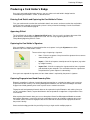
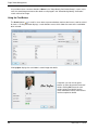
Capturing the Card Holder's Signature
If the card holder's signature is to be printed on the card, capture it using the Signature area of the
Biometrics tab in the Card Holders screen:
There are three ways of capturing a signature:
•
Live – Click this to capture a live picture of the signature from a camera
connected to your PC.
•
Import – Click this to import a stored picture of the signature (e.g. taken
by a digital camera).
•
Import Pad – Click this to capture the signature online from a signature
pad attached to your computer. The card holder writes the signature on
the pad and the system captures it automatically.
Once you have captured the signature, the icon shown above is replaced by the person's signature.
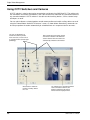
Capturing Fingerprint and Hand Geometry Data
Biometric recognition is taking an increasingly prominent position as a solution for today's ever-increasing
requirement for total security. The Security Management Software uses the latest technologies to enable
fingerprint and hand geometry to be used as part of access-control transactions.
Fingerprint and hand geometry biometric data can be captured using the Biometrics tab, making it easy to
set up a card holder's details, capture the biometric data and produce a badge from a single location in the
user interface.
After capturing the biometric data, you can use the optional Smart Card Management Module to encode
the biometric data onto a smart card, which the card holder presents to a biometric reader to gain access.
The reader checks the hand or fingerprint data on the card with the actual hand or fingerprint to confirm
the person's identity.
Smart-card technology provides the possibility of using a single card for multiple purposes.
SMS Software User Guide
33
Producing ID Badges
For detailed information, please refer to the online help in the SMS software. Alternatively, if you are using
813 fingerprint readers, you can obtain details of how to enroll fingerprints and use 813 readers from the
813 Fingerprint Reader User's Guide.
Selecting and Previewing the Badge Design
Before printing a badge, you must choose a badge design for the card holder using the Badge Design
pull-down menu in the Card Details tab.
Once you have selected the badge design, you can use the Badge button at the bottom of the Card
Holders screen to see a preview of the badge. The card holder's name, picture, etc. are automatically
inserted into the appropriate locations. The following shows an example, which uses the badge design
shown on page 32.
The preview screen contains Encoder Format and Smartcard Format options. You can use these to
define the format to be used when encoding the badge.
Printing and Encoding the Badge
If you wish to print an individual badge, you can simply click Print when viewing the preview of the badge,
as shown in the previous picture. A suitable combined printer and encoder will print and encode the card in
one operation.
Alternatively, you can save the card holder's details and use the "Home/Identity/Print Badges" screen to
print several badges in the same print run. The Print Badges screen displays a Selection screen, in which
you select the badges to print. Having done this, the screen shown in the following picture is displayed.
Selecting Print starts the printing/encoding process.
34
SMS Software User Guide
Producing ID Badges
For each card, the default badge design and
default encoder format are taken from the
"Home/Identity/Card Holders" screen. You can
override the defaults here.
Each person's badge is
displayed as it is being printed.
Smart Card Button
If the "Smart Card Encoding" license is installed, a Smart Card button is available in the Card Holder's
screen. Clicking Smart Card displays the following screen, which enables you to encode the card number
and optional biometric data onto the badge if it is a smart card used for access control:
®
This screen supports various smart card types, including Philips MIFARE, Philips MIFARE DESfire, HID ,
HID iCLASS™, and Texas Instruments™ (ISO 15693). Several different encoders are also supported.
SMS Software User Guide
35
5 Chapter 5:
Visitor Management
Setting Up Visitors
The Visitor Management features of the SMS software enable you to improve the efficiency of the visitor
check-in process, enhance site security and manage visitor details more effectively. The system allows
easy entry of visitor details through a dedicated "Home/Identity/Visitors" screen, which can be accessed
from any client PC or Web browser (with a Web Access license):
The screen can be used by any authorized employee to enter personal information about their visitors
before they arrive on site. This approach can significantly reduce check-in delays, improve efficiency and
enable security staff to verify a person's identity more carefully on arrival.
The "Home/Identity/Visitors" screen has been designed to enable people who are not normally users of
the Security Management Software to enter the personal details of their visitors. The Visitors screen is
similar to the "Home/Identity/Card Holders" screen.
Note: It is possible to give different users different levels of access to the "Home/Identity/Visitors" screen.
Some tabs in the screen may not be available, depending on you user privileges (defined in the
"Maintenance/User & Preferences/Roles" screen).
SMS Software User Guide
36
Visitor Management
Visitor Details
The Visitor Details tab enables you to specify general details of the visitor, such as when the visitor is
expected to arrive and depart, who he/she is visiting, and the name of the escort (if required). In a similar
manner to the "Home/Identity/Card Holders" screen, you can also capture the visitor's picture, choose a
badge design, then print the visitor's badge on a badge printer.
A major benefit of the Visitor Management module is the ability to sign visitors in and out from the Visitor
Details tab, using the Sign In and Sign Out buttons. Full details of when the visitor signed in and out are
maintained in the History box located near the bottom of the screen.
The current status of the visitor (Pending, Active or Closed) is displayed in a color-coded box near the
bottom-left corner of the screen, which can instantly show you whether the visitor is still on site.
If Email Notification of Visitor Signing In is selected in the "Maintenance/User & Preferences/System
Preferences" screen, an email is automatically sent to the card holder when the visitor is signed in. The
email address is defined using a personal data title in the card holder's details. The personal data title
must have a Category of type Email, as defined in the "Setup/Identity/Personal Data/Card Holder Titles"
screen.
The Visitor Details tab is also able to display a scanned or imported image of the visitor's business card.
This time-saving feature ensures speedy and accurate acquisition of basic information about a visitor,
such as address and contact information, and is of particular benefit in cases when the visitor details are
not entered before the visitor arrives.
Personal Details
The "Home/Identity/Visitors" screen includes a Personal tab, in which you can enter personal details of the
visitor in a similar manner to the Personal tab of the "Home/Identity/Card Holders" screen (see page 29).
The personal data titles can be different from those used for card holders and are set up in the
"Setup/Identity/Personal Data/Visitor Titles" screen.
Pre-defined data items for each of these personal data titles can be defined in the "Setup/Identity/Personal
Data/Visitor Data" screen. For example, if there is a data title named "Hair Color", you may want to define
data items such as "Black", "Brown" and "Blonde". You can select pre-defined data items from menus in
the screen.
Visitor Card Details, Access Rights and Biometrics
If the visitor requires an access-control card, you need to specify a card number and other details in the
Card Details tab. You also need to use the Access Rights tab to specify which areas the card holder can
access, and at what times. Setting up card details and access rights for a visitor is similar to setting up the
same details for a standard card holder, as described on page 21 and 23.
If biometric card readers are being used, it may be necessary to capture the visitor's fingerprints or hand
geometry before encoding the visitor's access-control card. You can do this using the Biometrics tab, in
the same way as for a standard card holder (see page 33). If magnetic stripe cards are being used, you
can encode the card at the same time it is being printed (assuming you are using a combined badge
printer and encoder).
SMS Software User Guide
37
Visitor Management
Once a visitor has left the site, it is possible to delete the card number from the visitor's details, then save
the details. This allows the card number to be assigned to another visitor, without deleting the previous
visitor's details, which may be reused if the visitor revisits the site.
Visitor Reports
The system provides extensive visitor reporting capabilities:
•
"Reports/Identity Reports/Visitors" – You can list details of visitor cards.
•
"Reports/Identity Reports/Access" – You can list details of the access rights of visitor cards.
•
"Reports/History/Activity" – You can view previous alarms and events generated by visitors.
•
"Reports/History/Cardholders Onsite" – You can find out which visitors used an entrance reader.
•
"Home/Identity/Locator" – You can find out the current location of selected visitors.
•
"Home/Identity/Muster" – The muster (roll call) report includes visitors.
All visitor transactions at access-controlled doors are recorded, and any infringements of site security are
immediately reported.
38
SMS Software User Guide
6 Chapter 6:
Digital Video Management
Introduction
The optional Digital Video Management module provides integration with CCTV and Digital Video
systems. The module enables video images to be viewed, recorded and replayed from easy-to-use
screens within the SMS software.
The Digital Video Management module provides an open platform that supports IP cameras connected
directly to the network, Symmetry Network Video Recorders (NVRs) and a wide range of Digital Video
Recorders (DVRs), as documented in the Digital Video Design Guide. If required, images can be recorded
continuously or at scheduled times of the day or night.
This chapter gives an overview of the screens and options available in the Digital Video Management
Module.
Note: Video Storage Management is used for the recording of video from IP cameras (page 45).
Summary of Key Features
The following is a summary of key features.
Virtual Matrix Screen:
39
•
Simultaneously displays multiple live images from digital video cameras.
•
Up to 72 simultaneous live images per PC, depending on PC specifications.
•
Includes controls for camera pan, tilt, zoom and focus.
•
Instant record feature.
•
Save, print and export images.
•
Camera sequencing.
•
Camera tours.
•
Supports display of web pages.
•
Instant replay feature.
•
Alarm and activity display.
SMS Software User Guide
Digital Video Management
Video Playback screen:
•
Allows easy replay of video recordings.
•
Filter options enable recordings to be located quickly from the database.
•
Simultaneous replay of up to four recordings.
•
JPEG picture export.
Tagging:
•
Tagged recordings produced by, for example, a Record Video trigger command or user recording,
are prevented from being overwritten and enable easy playback.
•
Also supports tagging by a user-applied "bookmark".
Camera Support:
•
A wide range of camera types is supported, including Symmetry and Axis IP cameras.
•
Maximum number of cameras is license dependent.
CCTV switcher integration:
•
Cameras attached to legacy CCTV switchers can be viewed, controlled and switched to any monitor.
•
Ancillary devices (such as lamps and wipers) can be switched on or off.
Commands:
•
Commands can, for example, run scheduled recordings and record incidents automatically (e.g.
from any intrusion or access event).
•
Supports commands to switch live video to the virtual matrix.
Playback from alarms or reports:
•
Incidents recorded automatically by an alarm or event can be easily replayed from history reports or
the "Home/Monitoring/Alarms" screen.
Graphics integration:
•
Live video can be played from a graphic, such as a plan or map of the building.
Identity Verification:
•
40
Operators can compare the live image of a card holder who is using a reader, against the stored
image.
SMS Software User Guide
Digital Video Management
Using the Virtual Matrix Screen
The "Home/Video & Audio/Virtual Matrix" screen enables you to simultaneously view live pictures from
digital video cameras or web pages. Each image is displayed in a "cell" located on the right-hand side of
the screen. Two Virtual Matrix screens can be open at the same time.
To display live images, find the camera or web page in the tree view, then drag and drop it into a cell. You
can also drag and drop images from one cell to another. Double-clicking an image displays the image in
the largest cell.
Note: Black or gray areas in a picture indicate "privacy zones" configured by the installer.
You can change the
number of cells displayed
and their positions using
the Change Layout option.
The tree view contains the digital
video cameras set up in the
Install screens, and all Web
pages added using the Create
URL button, which is located
above the tree view.
SMS Software User Guide
Once you have decided which cameras and/or Web pages to
view, and have moved each into a cell, you can save the
configuration as a "view" using the Save button. The next time
you open the screen, you can select the view from the pull-down
menu, which automatically displays the Web pages and camera
images in that view.
Clicking here can display a control to zoom in/out, focus, pan, tilt
and focus the camera, or to move the camera to a preset position.
The control makes available only those functions the camera
supports.
This panel enables you to start
camera sequencing, display an
image full screen, show alarms,
show current activity and start/stop
camera tours.
The right-click menu
provides context-sensitive
options; for example, to
record or replay video.
41
Digital Video Management
Using the Video Playback Screen
The "Home/Video & Audio/Video Playback" screen enables you to replay video recordings. Up to four
recordings can be simultaneously replayed in "cells" located on the right-hand side of the screen. You can
swap between displaying one and four cells by right-clicking on a cell and selecting/deselecting Expand
Cell.
You can change playback speed,
or pause and play the recording.
This lists the
recordings available
for the selected
cameras.
The time line shows periods during which
recordings exist for the currently selected cell,
and your current position in the recording. You
can drag and drop the marker to replay from a
different time. The different colors in the time line
indicate different types of recording, e.g.
bookmarked recordings, or recordings started by
an alarm condition.
You can use these options to
perform actions such as to save
the recording as an MPEG-4 file,
zoom in or out of the time line and
bookmark periods of interest.
To play a recording:
42
1.
In the tree view located near the top-left corner of the screen, select the camera(s) that made the
recording(s).
2.
Use the Include pull-down menu to specify the types of video recordings to find from the database.
Select All Video if you want to find all recordings.
3.
Specify the date and time range of the recordings to find.
SMS Software User Guide
Digital Video Management
4.
Click the Search ( ) button. The panel near the bottom of the screen lists all recordings that are of
the correct type and include any part of the time period specified by the From and To fields.
5.
Drag and drop any listed recording into a cell, or double-click. Playback starts from the Start time
shown in the panel.
Identity Verification
The "Home/Identity/Identity Verification" screen displays live video from all cameras in a selected identity
verification group, as set up in the "Setup/Identity Verification/Groups" screen. Cameras connected directly
to the PC can be used (such as a webcams). If Digital Video Management is installed, digital video
cameras can also be used.
An identity verification group can contain up to four cameras, and each camera has an associated reader.
For example, the "Front Door" reader may be associated with the "Front Door" camera. When there is a
transaction from a known card at an associated reader, the stored image of the card holder or visitor is
displayed next to the live image. This enables a guard to compare the two images to verify the person's
identity. For example:
If there is an invalid transaction (such as At Wrong Door), the card holder's stored image is outlined with a
flashing red border.
The field below the pictures displays information about the transaction made at the reader. The remaining
three fields provide additional information, such as the person's full name, card and card expiry date. The
information to display is specified the "Setup/Identity Verification/Setup" screen.
If necessary, the system can be set up in "PC Door Control mode", which requires the guard to select
Grant Access ( ) or Deny Access ( ) for each transaction.
If only one camera is used and Rotate in 2 x 2 View is selected in the "Setup/Identity Verification/Groups"
screen, the screen displays the last four verification transactions, with the associated images.
SMS Software User Guide
43
Digital Video Management
It is possible to have a camera selection of None in the "Setup/Identity Verification/Groups" screen. In this
case, the stored image and transaction details are displayed in the "Home/Identity/Identity Verification"
screen, with no live image.
Using the Find Button
The Search button ( ) is useful in cases where a person who does not have their access card has asked
for access. Clicking the button displays a card selection screen, which allows the name of the card holder
to be selected:
Clicking Open displays the card holder's stored image and details:
If required, you can use the green
buttons to select the previous/next card
holder. Clicking OK inserts the card
holder's picture and details into the
Video Verification screen, where access
can be accepted or denied.
44
SMS Software User Guide
Digital Video Management
Video Storage Management Module
The Video Storage Management Module is used to create Symmetry NVRs, which store video from IP
cameras to a network storage device.
The system can be set up with one or more Symmetry NVRs. A Symmetry NVR is provided "as standard"
on the database server when the Digital Video Management software is installed. If required, licenses for
additional Symmetry NVRs can be installed.
Configuration of data storage is set up using the "Install/Video & Audio/NVR Settings" screen, as shown
next.
You can set up schedules that automatically purge recordings from
the storage device that are older than a specified number of days.
Different purge settings can be defined for different types of
recordings (e.g. tagged video can be purged less often).
Multiple storage locations can be set up to store
video from each device. If the location at the top
of the list becomes full, the next location is used.
SMS Software User Guide
45
Digital Video Management
Using CCTV Switchers and Cameras
A CCTV switcher is a device that can be connected to a serial port of an SMS client PC. The switcher unit
has connections for cameras and monitors, and is able to switch live video from any connected camera to
any connected monitor. A CCTV switcher is also able to switch ancillary devices, such as camera lamps
and wipers, on or off.
You can switch video to a selected monitor, control camera position and switch ancillary devices on or off
using the "Home/Video & Audio/CCTV Cameras" screen, as shown below. Alternatively, commands can
be set up to perform the actions automatically at scheduled times or in response to alarms or events.
You can use the buttons to
control the camera's pan/tilt,
zoom and focus, and to move it
to a preset position (camera type
permitting).
These buttons switch the
camera's ancillary devices
on or off.
46
These shows the name of the camera
and monitor selected in the Selection
screen. Pictures from the camera are
automatically switched to the monitor.
If a switcher has a separate hardwired
video connection to the PC, the
pictures displayed at the CCTV
monitor are also displayed here.
SMS Software User Guide
Digital Video Management
Viewing a CCTV Image During Alarm Acknowledgement
A Command button is available when acknowledging an alarm from the "Home/Monitoring/ Alarms"
screen, which could be used to switch the CCTV camera at the alarm location to a pre-defined monitor.
This enables the operator to view the images at the alarm location quickly and easily. You can set up the
command activated by the Command button using the "Operation/Alarms/Commands" screen.
Digital Video and CCTV Switcher Commands
Commands from the SMS software include the following.
Digital Video Camera Commands
•
Live Video – Displays live video from the selected digital video camera.
•
Modify Video Settings – Changes the video settings of the selected camera.
•
PTZ Preset – Moves the selected camera to a preset position.
•
Record Video – Records video from the selected digital video camera.
•
Start/Stop Recording – Starts/stops recording for the selected digital video camera.
•
Switch Live Video – Switches live video from a digital video camera to a cell in the "Home/Video &
Audio/Virtual Matrix" screen.
•
Video Instant Replay – Automatically displays a window showing recorded video from a selected
camera.
•
Enable/Disable Motion Detection – Enables/disables motion detection for a selected camera.
CCTV Switcher Commands
•
Activate Alarm – Causes a pre-programmed action to occur at the CCTV switcher (trigger command
only).
•
Reset Alarm – Cancels the Activate Alarm command (trigger command only).
•
Ancillary On/Off – Switches the CCTV switcher ancillary device on/off.
•
Switch to Monitor or the name of the camera – Switches video from the selected camera to a
selected CCTV monitor.
SMS Software User Guide
47
Digital Video Management
Playback from Alarms and Reports
Video recordings created by a Record Video command can be easily replayed from the
"Home/Monitoring/Alarms", "Home/Monitoring/Activity" or "Reports/History/Activity" screens. For example:
Any alarm that has an
associated video clip
displays this icon in the
"Home/Monitoring/Alarms
" screen.
You can replay the
video clip by clicking
Replay.
Graphics Integration
Digital video and CCTV switcher cameras can be added to graphics using the "Setup/Graphics/Setup"
screen. Adding cameras to a graphic makes it easy for you to locate a camera on the
"Home/Monitoring/Graphics" screen and to view live video from that camera. Right-clicking the icon for an
IP camera displays the following:
You can view live video from the
camera or start/stop recording.
48
SMS Software User Guide
Digital Video Management
Right-clicking a CCTV switcher camera displays the following.
You can switch the image from the
CCTV switcher camera to the
selected monitor.
SMS Software User Guide
49
7 Chapter 7:
Alarms Monitoring
Understanding Alarms Monitoring
Each major action that takes place at devices such as readers and monitor points is classed as either an
event or alarm. Events are non-serious conditions and are simply logged for future reporting. Alarms,
however, (such as "Door Forced") are potentially serious violations of security and are always displayed in
the "Home/Monitoring/Alarms" screen, which forms the central part of the system's alarms monitoring
capabilities.
Note: It essential that the user who is tasked with alarms monitoring is either logged into the SMS
software or has the Login screen displayed.
How New Alarms are Signaled
When a new alarm occurs, the PC that is receiving the alarms makes a sound, which can be set up to vary
depending on the alarm type and location of the alarm. If the Login screen is displayed and there is at
least one uncleared alarm, alarm details are shown in a box in the bottom-left corner of the screen:
The box shows:
•
The number of new alarms, i.e. the number of alarms that you have not yet acknowledged. You will
find out how to acknowledge an alarm later in this section.
•
The total number of uncleared alarms.
•
The highest priority of any alarm (1 is the highest priority, 999 is the lowest).
If you are logged in, this information is shown at the bottom of the display area, together with a Silence
button to stop the sound:
When there is a new alarm, you will see a flashing blue/red light in the Windows System Tray. This
changes to the standard SMS software icon ( )after all alarms have been acknowledged. In addition, you
may see "Alarm!" in the background of the main window (depending on client preferences).
If your system has been set up for real-time printing, details of the alarm are automatically printed. It is
normal to use an impact printer that has continuous stationery for this purpose.
Your system can also be set up to display a graphic of the alarm location or to send an email to a
nominated person.
SMS Software User Guide
50
Alarms Monitoring
About the Alarms Screen
You can use the "Home/Monitoring/Alarms" screen to view, acknowledge and clear alarms. The Alarms
screen provides full details of all alarms that have not yet been cleared.
Ideally, you should keep the Alarms screen displayed at all times, since it allows you to read the details of
new alarms as soon as they occur.
There are two different appearances for the Alarms screen: the default appearance and the combined
alarm/acknowledgement appearance, as described next. The appearance can be changed using the
Show Combined Alarm / Acknowledgement Screen option in the "Maintenance/User &
Preferences/Client Preferences" screen.
Default Appearance of the Alarms Screen
The default appearance, which is shown above, has the following features:
Alarm List
Alarms are listed in the upper area of the screen. Details of each alarm are given, including the alarm
message, location and the name of the person who caused the alarm (if known). The alarms are colorcoded as follows:
•
Red alarms are new alarms that have not been acknowledged.
•
Blue alarms have been acknowledged, but require a device to be reset (such as sensor returning to
its normal state). The alarm cannot be cleared until the device is reset.
•
Green alarms have been acknowledged and, if necessary reset, but have not yet been cleared.
Clearing an alarm removes it from the Alarms screen.
Red alarms are listed first, followed by blue then green. For each color, the alarms are also listed in order
of priority.
SMS Software User Guide
51
Alarms Monitoring
Alarm Statistics
The default appearance of the alarms screen is able to display a pie chart and alarm statistics. These are
shown in the lower area of the screen. You can change the viewing angle of a chart by clicking on the
picture and moving the mouse.
Acknowledging an Alarm, Viewing Instructions and Adding Comments
You can acknowledge an alarm, view alarm instructions, enter new comments and review previous
comments by double-clicking the alarm. A separate Acknowledge Alarm screen is displayed; for example:
The Acknowledge Alarm screen displays the instructions that you should follow (in this case, "Send Guard
to Investigate", as shown near the top-right corner). The instructions are specific to the type of alarm and
are set up using the "Operation/Alarms/Instructions" and "Operation/Alarms/Definitions" screens.
The Acknowledge Alarm screen also provides a Comments area, where you can record the actions taken.
You add a comment either by typing text in the box or by clicking Select Standard Comment and
choosing one of the predefined comments. Predefined alarm comments are set up using the
"Operation/Alarms/Comments" screen.
Clicking OK acknowledges the alarm and displays the Alarms screen, which now shows the alarm in blue
(alarm acknowledged, but device not reset) or green (alarm ready to be cleared).
If required, you can return to the Acknowledge Alarm screen to add more comments by reselecting the
alarm in the Alarms screen. Your previous comments are shown in the Previous Comments box, as
shown in the following picture.
52
SMS Software User Guide
Alarms Monitoring
Each comment in the Previous Comments box is prefixed with the name of the user who added the
comment and the time that the comment was added.
The
button (to the right of Select Standard Comment) is ungrayed if a command has been set up for
the alarm in the "Operation/Alarms/Commands" screen. Selecting the button sends the command. The
command may, for example, record video at a selected camera.
Clearing an Alarm
An alarm can be cleared (i.e. removed from the Alarms screen) by clicking Clear in the Alarm
Acknowledgement screen. You may also want to add a comment before selecting Clear, such as
"Supervisor Notified".
SMS Software User Guide
53
Alarms Monitoring
Combined Alarm/Acknowledgement Appearance
An example of the combined alarm/acknowledgement appearance for the Alarms screen is shown next.
This is displayed if the Show Combined Alarm / Acknowledgement Screen option is selected in the
"Maintenance/User & Preferences/Client Preferences" screen.
The combined appearance contains the same list of alarms as the default appearance, but a selected
alarm can be acknowledged by clicking the Acknowledge button, or cleared by clicking the Clear button.
Selecting an alarm also displays any alarm comments and instructions associated with that alarm.
The toolbar along the left side allows you to perform functions such as to print an alarm, select a standard
comment, send an alarm command and view the image of the card holder who is associated with an
alarm.
54
SMS Software User Guide
Alarms Monitoring
Setting Up Alarm Filters
Clicking the Filters (
) button in the Alarms screen displays the following screen, which enables you to
define one or more alarm filters:
Each filter you define creates an extra tab in the Alarms screen. The tab displays only those alarms that
the filter is set up to display. Each SMS client can display different alarm filters.
Alarm filters provide a method of partitioning the viewing of alarms in the Alarms screen. You can, for
example, create an alarm filters to display only alarms of a specified type or from a specified location, or
combinations of different alarm types.
The panel near the bottom of the screen shows how the currently selected alarms filter is set up. In this
example, the "Entrance Readers" filter will display alarms from "Entrance 1 Reader" or "Entrance 2
Reader".
Viewing a Graphic of the Alarm's Location
If graphics have been defined for your installation, clicking on an alarm, then selecting the Graphic (
button displays a graphic of the alarm's location.
)
Graphics can also be viewed at any time in the "Home/Monitoring/Graphics" screen, or they can be set up
in the "Maintenance/User & Preferences/Client Preferences" screen to be displayed automatically.
SMS Software User Guide
55
8 Chapter 8:
Producing Reports
Introduction
The reporting features within the Security Management Software enable comprehensive listings of alarms,
events, user actions, access rights, configuration settings and other information to be produced, giving full
traceability of all essential information.
It's easy to produce a wide range of different types of report. You can, for example, produce reports of the
card holders who have been granted access through specified doors, the people who have attempted to
gain entry into unauthorized areas, and the actions taken to acknowledge alarms.
Using the reports provided, you can quickly find the information you need. The extensive filtering options
ensure that the reports display only the information you require, leading to improved clarity and ease of
use.
For added flexibility, the system enables a library of customized reports to be defined, which can printed
automatically at scheduled intervals. For ultimate customization of report format and content, integration
®
with the popular Crystal Reports software is provided.
The reporting system is essential for any manager who needs to be assured that attempted breaches of
security or other incidents can be investigated properly and quickly, or who requires comprehensive paper
records of how the system has been configured.
Activity Report
You can generate an activity report from the "Home/Monitoring/Activity" screen at nominated client
machines, as set up in the "Install/System/Clients" screen. The report displays all alarms and events as
they occur.
SMS Software User Guide
56
Producing Reports
The report includes a History button that displays on a day-by-day basis any alarms and events that have
been recorded in the system's log. For example:
Reports Available from the Reports Tab
You can run several different types of report (depending on the modules installed ) from the Reports tab of
the SMS software:
The meaning of each report shown above is as follows.
"Reports/History":
•
Activity – Produces full details of previous alarms and events. See the example in the next section.
•
User Audit – Lists previous user actions within the screens of the SMS software.
•
Onsite Times – Lists the amount of time card holders have spent on site. The report can, for
example, be used to verify contractor invoices.
•
Cardholders Onsite – Lists the cards that are currently on site. The report could be used by
emergency services.
SMS Software User Guide
57
Producing Reports
•
Patrols – Produces information about previous patrol tours (see the Guard Patrol Manager
Installation & User Guide). The report provides details of when patrol tours were started and
completed and any rule infringements.
•
Video Archive Audit – Examines the date and time of each recording stored in a video storage
folder of a Symmetry NVR, and shows the date and time of the most recent recording for the
selected camera(s).
•
Predefined Reports – Enables you to run a report that has been previously set up and customized
from the "Reports/Configuration/Predefined Reports" menu. You can run the report manually, or
automatically at scheduled intervals. Predefined reports enable you to set up a library of your
favorite reports, which saves time if you need to run the same report frequently.
"Reports/Identity Reports":
•
Cards – Lists the details of how cards have been set up in the "Home/Identity/Cards" or
"Home/Identity/Visitors" screen. See the example in the next section.
•
Access – Enables you to produce different types of access-rights listings:
−
Card holders who can use a specified door.
−
Cards that are to expire between specified badge or inactive dates.
−
Cards unused for a specified number of days.
−
Cards using a specified access code or time code.
−
Card holders who can use a specified floor/output group or reader group.
−
Doors that can be accessed by a specified card.
See the example in the next section.
•
Visitors – Produces a report of current, previous or future visitors. You may, for example, want to
run a report that shows all the visitors expected on a specified date. See the example in the next
section.
"Reports/Configuration":
58
•
System Configuration – Displays a tree view of how the SMS software is set up. See the example
in the next section.
•
Reports – Enables you to produce a large number of different reports to view how readers, holidays,
time codes, users, commands, etc. have been set up.
•
Predefined Reports – Allows you to define customized reports to run from
"Reports/History/Predefined Reports".
SMS Software User Guide
Producing Reports
Examples
Example – "Reports/History/Activity"
Example – "Reports/Identity Reports/Cards"
SMS Software User Guide
59
Producing Reports
Example – "Reports/Identity Reports/Access"
Example – "Reports/Identity Reports/Visitors"
60
SMS Software User Guide
Producing Reports
Example – "Reports/Configuration/System Configuration"
Muster (Roll Call) Reports
A muster report (available only with the "Safety Roll Call Management Module") shows a list of people who
are recorded by the SMS software as being in the building, together with details of the last reader they
used. It is intended to be used during fire or other emergencies to assist the rescue services. The following
is an example of a muster report:
Muster reports can be produced automatically when a monitor point triggers, such as an output of an
alarm. You can also produce then manually using the "Home/Identity/Muster" screen.
SMS Software User Guide
61
Producing Reports
Muster Report Configuration
The muster report must first be set up using the "Setup/Identity/Muster" screen:
You can choose to order
the card holders in the
report by name or card
number.
You can organize the report
into separate sections (e.g.
by department).
A person is included in the
report only if the last reader
used is an on-site reader.
A card holder is removed from
a muster report when he or
she performs a transaction at
a muster reader.
The report can be started
automatically when a monitor
point such as an alarm trigger
(Auto Start), or manually from the
"Home/Identity/Muster" screen
(Manual Start).
This prevents the first report
being produced until there are
fewer than a specified number of
people left to muster.
You can send the report to
more than one location.
The report repeats itself
automatically until there is no-one left
in the building or until you reset it.
The delay should be to give
most people enough time to
reach a muster reader.
Monitoring a Muster
You can monitor the muster progress from the "Home/Identity/Muster" screen, as shown next. The screen
gives an immediate view of the number of people left on site and the status of the muster.
62
SMS Software User Guide
Producing Reports
As soon as a card holder makes a transaction at a muster reader or any other reader that is not an on-site
reader, he/she is removed from the next report.
Note: The system ignores a transaction at a reader if it generates a Door Not Opened alarm/event.
When the emergency (or drill) is over, you need to reset the muster from the "Home/Identity/Muster"
screen. During the reset, you can select a reader; the system performs an automatic transaction at this
reader for everyone whose last transaction was a muster reader. This allows everyone to be included in
another muster report, should it be started immediately after the one you are resetting.
Locator Reports
There are two types of locator report. The first is actually a tab of the Card Holders or Visitors screen,
rather than a true report. It lists the card holder's last 25 transactions (see page 29).
The second is accessible from the "Home/Identity" menu and shows, for each selected card holder, the
name of the reader that last granted access. This can help you to determine the current location of one or
more card holders. For example:
SMS Software User Guide
63
9 Chapter 9:
Other Features
This chapter describes other key miscellaneous features of the SMS software.
Setting Up User Roles and Accounts
A user is a person who uses the SMS software on an SMS client PC. There are two stages to setting up
users:
1.
Use the "Maintenance/User & Preferences/Roles" screen to define one or more user roles. Each
role (e.g. System Manager) specifies a set of permissions to the screens of the Security
Management Software.
2.
Use the "Maintenance/User & Preferences/Accounts" screen to create the user's account, which
specifies the user's login name, password and role.
Setting Up Roles
Roles are set up in the "Maintenance/User & Preferences/Roles" screen:
SMS Software User Guide
64
Other Features
A role defines a set of access privileges to the screens of the SMS software. A series of roles can be set
up for different categories of user. In the example shown above, the role has been named "Security
Guard", which could be assigned to any user who needs to perform guard tasks in the SMS software.
Each role provides four levels of access to each screen: View (orange), Modify (blue), Delete (green) and
None (red). If, for example, you set the access to a screen to be view only, users who belong to the role
will be able to view the contents of the screen, but nothing else. Modify access allows users to alter the
information in the screen, and Delete access enables users to delete complete records, such as a card
holder.
Roles enable the range of tasks to be carried out by each type of user to be restricted, which not only
enhances system security, but also simplifies the user interface, since the system displays menu options
for only those screens that a user has access to. Roles make it easy to set up the privileges of new users
or modify the privileges of existing users.
As with most computer systems that offer these types of security arrangements, only one user should
have full access to all options (and, if applicable, to every company's information).
Creating User Accounts
You can create a user's login name and password, and assign the user to a role using the
"Maintenance/User & Preferences/Accounts" screen:
If different SMS language packs
are installed, you can choose the
language to use for the user.
When the user logs in, menus
and options will be displayed in
the specified language.
SMS Software User Guide
65
Other Features
A simple selection of the role (in the User Role menu) instantly sets up the user's required privileges.
The Secure Logon options enable logons to be accepted only after a user has presented a smart card or
fingerprint at an appropriate reader. The Cardholder Fingerprint Enrollment Options are used when
enrolling fingerprints in the "Home/Identity/Card Holders" or "Home/Identity/Visitors" screen.
Sending Commands
The ability to send commands is an extremely powerful feature of the SMS software, which enables you to
change the status and mode of operation of devices such as readers, monitor points, auxiliary outputs and
cameras.
There are three types of commands:
•
Manual Commands – These enable you to change the status or mode of operation of a device
immediately. For example, you can send a manual command to release a door's lock, or to switch a
reader from card-only mode to card-and-PIN mode.
•
Scheduled Commands – These cause commands to be executed at pre-defined times each day.
For example, you could set up a scheduled command to start a video recording at the same time
each day.
•
Trigger Commands – A trigger command is executed only when a defined action takes place. For
example, a CCTV camera could be switched to a specified SMS client when an alarm sensor is
triggered, or doors can be unlocked on an alarm. Trigger commands are also known as conditional
or "If, Then, When" commands.
The following sections explain the different types of command in more detail.
Note: A time-saving feature is the ability to send a single command to a group of monitor points, readers
or auxiliary outputs (created using the options in the "Setup/Device Groups" menu). The command is then
executed at all devices in the group.
66
SMS Software User Guide
Other Features
Manual Commands (Command Center)
You can send manual commands using the "Home/Monitoring/Command Center" screen. The commands
available depend on the selected device. In the above example, the Front Entrance camera is selected in
the tree, and any of the commands shown in the panel on the right-hand side of the screen can be sent to
that camera. Selecting a different device type displays a different set of commands in the panel.
The "Home/Monitoring/Command Center" screen also displays the current status and mode of operation
of a device in a tree view. In the example, the tree view shows that the "Main Building Front Door" reader
is enabled and in card-only mode, keycard mode is switched off, etc.
The "Home/Monitoring/Command Center" screen provides real-time status monitoring, which means that
any changes in the information that you are viewing are displayed immediately; you do not have to exit
and re-enter the screen.
If required, you can also send commands from other screens in the SMS software , such as from the
"Home/Monitoring/Graphics" screen.
SMS Software User Guide
67
Other Features
Scheduled Commands
Scheduled commands can be set up using the Scheduled Commands screen
("Operation/Commands/Scheduled"). For example:
Scheduled commands consist of a start command, stop command and time code. The start command is
executed at each start time in the time code, and the stop command is executed at each stop time.
Consider the following example, which reflects the scheduled command set up in the previous picture:
Time code ("Busy Times"):
08:00 to 09:00 Monday to Friday
17:00 to 18:00 Monday to Friday
07:30 to 08:30 Saturday only
08:30 to 09:30 Sunday only
Start command: Unlock Door
Stop command: Lock Door
This example shows a scheduled command that could be used to unlock and re-lock the main door to the
Assembly Area at busy times of the day. The start command is Unlock Door, which enables people to gain
access without having to use their cards. The command is executed at 08:00 Monday to Friday, 17:00
Monday to Friday, 07:30 on Saturdays and 08:30 on Sundays.
68
SMS Software User Guide
Other Features
The stop command is Lock Door, which means that after the command, people gain access in the normal
way; that is, by presenting a card to the reader. The command is executed at 09:00 and 18:00 Monday to
Friday, 08:30 on Saturdays and 09:30 on Sundays.
It is normal, although not compulsory, for the start and stop commands to have opposite effects.
Scheduled commands can also be useful to switch readers into different modes. For example, as an
added security measure, you may want to switch readers into card-and-PIN mode during the night.
You can also enable and disable a monitor point or a group of monitor points, which may be useful if
people want to open, for example, monitored fire exits during the day.
An auxiliary output or a group of auxiliary outputs can also be switched on or off according to time of day,
which may be appropriate for external lights or other devices.
Trigger Commands
Scheduled commands bring a great deal of flexibility to the security management system, but even more
flexibility is achieved through the use of trigger commands (otherwise known as conditional commands),
as set up in the "Operation/Commands/Trigger" screen. The following picture shows an example of a
trigger command, which is generated when the "Side Entrance Reader" generates a "Door Forced" alarm.
SMS Software User Guide
69
Other Features
A trigger command is executed if a specified alarm/event message is generated from a specified
device/card between a start and stop time of a specified time code. Consider the trigger command set up
in the example:
Device name:
Side Entrance Reader
Alarm/event message:
Door Forced
Command to:
Side Entrance (a camera)
Command:
Record Video
Time code:
All times
In this example, if the Side Entrance Reader generates the "Door Forced" alarm at any time, then the Side
Entrance camera records video.
In this case, the command is triggered as a result of an alarm/event from a reader, but you can also trigger
commands from, for example, a monitor point or card alarm/event. If you choose a group, such as a
monitor group or reader group, the command is triggered if any device in the group generates the selected
alarm/event.
Threat Level Management
The optional Threat Level Manager features of the SMS software enable you to change a building's
security at the click of a button. You may want to enhance security when there is a greater threat of
criminal or terrorist activities, or during times of limited occupancy such as holiday or site shutdown
periods, and lower it at other times. Five threat levels are available, each of which you can customize
using the "Setup/Configuration/Threat Levels" screen to provide a different level of security:
Changing the threat level (in the "Home/Monitoring/Change Threat Level" screen) can determine which
cards have access, which areas they can access and the scheduled and trigger commands that can
operate. For further information, please read the Threat Level Manager Installation and User Guide.
70
SMS Software User Guide
Other Features
Guard Patrol Management
The Guard Patrol Manager is an optional module for configuring, recording and reviewing guard patrols.
The module includes a complete set of tools for setting up and managing patrols entirely from the SMS
software. It benefits from the ability to use access-control readers as tour checkpoints, resulting in the
need for no specialist hardware or data-collection devices, and making the introduction of patrol
management both cost-effective and easy to implement.
Patrols can be set up to specify the sequence of checkpoints to visit and the time allowed for the guard to
travel between them.
The progress of a patrol can be monitored, and previous patrols reviewed in reports. Of particular benefit
in high-security applications is the ability for the system to notify SMS operators immediately of any rule
infringements, such as missed checkpoints or late arrival.
For further information, please read the Guard Patrol Manager Installation and User Guide.
Graphics Screen
A graphic is typically a map or plan of the building, which can contain icons representing devices such as
readers, doors, video cameras and alarm sensors. Graphics allow operators to monitor the status of
devices, locate them in the building and control their mode of operation, such as to grant access through a
selected door, connect to an intercom or start a recording at a selected video camera. Graphics make it
easy to determine the location of an alarm and to send personnel quickly to an incident, leading to
improved site security and efficiency.
Graphics are configured using the "Setup/Graphics/Add" and "Setup/Graphics/Setup" screens, and can be
monitored using the "Home/Monitoring/Graphics" screen. An example of the "Home/Monitoring/Graphics"
screen is shown next.
SMS Software User Guide
71
Other Features
Selecting a device shows its status near the top of the screen. This example shows the status of the
selected monitor point as Enabled / Normal State. The border of a device icon also indicates its status;
red indicates an alarm state. The example also shows the right-click menu for a monitor point, which gives
access to options such as Disable Monitor Point and Enable Monitor Point.
Graphics can contain links to other graphics, enabling an operator to locate an alarm or device with
increasing accuracy. To make response times even quicker, a graphic can be set up to be displayed
automatically when an alarm occurs.
Creating and Managing Tasks
The "Home/Monitoring/Tasks" screen allows you to create and manage tasks. A task defines an action
that must be completed by a specified user, or by any user that has a specified user role. Each task has a
due date and time; if the task is not completed on time, its status automatically changes to "overdue".
The Tasks screen lists all completed and uncompleted tasks. For each task, the screen shows the task
subject, the due date and time, the name of the user or user role the task is assigned to, and the current
status of the task. The following shows an example.
72
SMS Software User Guide
Other Features
You can use the options in the upper area of the Selection screen to apply filters, which cause only tasks
that match selected criteria to be displayed. You can open a task (e.g. to add comments or mark the task
as completed) by selecting the task and clicking Open.
Creating a New Task
You can create a new task by clicking New in the Selection screen. This displays the screen shown next.
SMS Software User Guide
73
Other Features
When you create a task, you specify:
74
•
Due on – The due date and time of the task. If the task is not completed on time, its status
automatically changes to "overdue".
•
Assigned To – The name of the user or user role that is assigned the task. If the task is assigned to
a user role, any user who has that role can complete it.
•
Subject – The task subject, which should be a brief description of the task.
•
Alarm – Whether to generate an alarm if the task becomes overdue or immediately on creation of
the task.
•
Details tab – Any instructions to complete the task.
•
Comments tab – Any additional comments about the task. Additional comments can be added
when managing or completing the task.
•
Recurrence tab – The recurrence period, such as every day or every Friday. When the task is
completed, a new instance of the task is automatically generated, with a due date that reflects the
recurrence period.
•
Attachments tab – File attachments for the task, such as diagrams or plans.
SMS Software User Guide
Other Features
Completing a Task
You can mark a task as complete by opening the task and clicking the Complete button. Alternatively, if
the task has caused an alarm, you can open the alarm in the "Home/Monitoring/Alarms" screen and click
Complete.
Completing a task removes it from the "Home/Monitoring/Alarms" screen and generates a new task,
depending on the settings in the Recurrence tab.
Completed tasks are deleted automatically after the period specified by Purge Daily Logs After in the
"Maintenance/User & Preferences/System Preferences" screen.
Handling Task Alarms
A task appears in the "Home/Monitoring/Alarms" screen if it generates an alarm, which can occur
immediately on creation of the task, or when the task is overdue (depending on the setup of the task).
Double-clicking a task in the Alarms screen allows you to view the details of the task, in the same way as
opening the task from the Tasks screen.
Completing a task removes it from the "Home/Monitoring/Alarms" screen.
The number of unacknowledged task alarms is displayed in the bar along the bottom edge of the main
window. For example:
Workflow Designer
You can use the "Setup/Workflow/Workflow Designer" screen to create, find, view, modify, copy or delete
workflows. A workflow is a set of actions that are started automatically when you perform a selected
operation, such as opening a new alarm, acknowledging an alarm or opening a task. You can choose the
type of trigger that starts a workflow and the actions that the workflow carries out. You can, for example,
create a workflow that:
•
Automatically opens the Graphics screen when you open a new alarm.
•
Opens the Virtual Matrix screen when there is a Granted Access transaction at a door.
•
Prompts the user to record whether an alarm (detected by a monitor point) was a drill or
unscheduled.
•
Automatically clears or acknowledges an alarm of a specific type when you open it.
A workflow can contain more than one action. For example, a workflow can open a screen, display an
instruction and create a task when you open a new alarm. In addition, a workflow can contain different
paths depending on your responses to questions.
The following shows an example of a workflow created in the "Setup/Workflow/Workflow Designer" screen.
SMS Software User Guide
75
Other Features
If you choose an alarm-based trigger, you can specify that any alarm from any device can trigger the
workflow, or only selected alarms from certain devices. The Conditions area in the Workflow Designer
allows you choose the devices and alarms. By default, workflows are triggered by any alarm from any
device.
Triggers and Actions
When you create a workflow, you specify the trigger that starts the workflow. Triggers are either alarm
based, such as "Open New Alarm" and "Open Existing Alarm", or task based, such as "Create Task" and
"Complete Task". The trigger in the above example is "Open New Alarm" (shown near the top of the
screen).
The selected trigger determines the actions you can drag and drop from the menu on the left into the
Workflow Designer. Actions include "Create Task", "Email", "Open Window", etc. The order you place the
actions in the workflow determines the order in which they are executed.
Some actions have associated options. For example, the "Open Window" action has an option that allows
you to choose the screen to open (selected from the panel in the bottom-left corner of the screen). The
"Create Task" action has a greater set of options, which can be displayed in a separate window.
The first action in the above example is "Open Window", which opens the Graphics screen. This is
followed by "Question" action, which has a branch for a Yes response and another for a No response. The
Yes branch has a "Show Instruction" action. The No branch has "Show Instruction" and "Create Task"
actions.
76
SMS Software User Guide
Other Features
Multiple Workflows
More than one workflow can be set up with the same trigger. The Priority button allows you to specify the
order in which the workflows are executed.
Web Access
The optional Web Access module enables you to monitor, control and administer your Symmetry Security
Management System using Microsoft Internet Explorer or the Citrix Program Neighborhood software over
the Internet or through your company's intranet.
Using the Web Access module, you have the ability to perform a wide range of tasks, such as setting up
card holders, producing badges, generating reports, viewing digital video, monitoring alarms and
registering visitor details. A Web Client requires no sentinel or special software to be installed, making it
the ideal choice for users who require casual access to the SMS software from any location.
The user interface at a Web Client is the same as is displayed at a standard client of the SMS software.
This enables users to obtain the full benefits from the easy-to-use software and eliminates the overhead of
learning a new user interface.
For further information, please refer to the Web Access Installation and User Guide.
Reader Modes
Readers are, of course, a key element of your Security Management System and their behavior must be
matched to your site's specific requirements. Readers can be switched into several different modes,
including the following.
Card-and-PIN Mode
By using commands, you can switch any reader that has a keypad between card-only and card-and-PIN
mode. When a reader is in card-only mode, there is no need to enter a PIN to gain access. With card-andPIN mode, a PIN has to be entered, unless the card holder has executive card privileges, as set up in the
Card Holders screen.
It may be a good idea to switch to card-only mode at busy times of the day by using a scheduled
command.
User-Code Mode
User-code mode can be used by keypad readers. When a reader has been enabled for user-code mode,
card holders are able to gain entry without their card by:
1.
Pressing the # key.
2.
Entering the card number (no need to enter leading zeroes).
3.
Pressing the * key.
There is no need to present the card to the reader (although the use of a card will be accepted in the
normal way).
SMS Software User Guide
77
Other Features
You can enable user-code mode by sending the User Code Only or User Code + PIN command to the
reader. User Code + PIN forces card holders to enter a PIN as well as the card number while the reader is
enabled for user-code mode.
You can disable user-code mode by sending the User Code Disable command to the reader.
Card-Command Mode
Card-command mode enables a card holder who has the Command Card Holder option set in the
"Home/Identity/Card Holders" screen to generate card command messages at keypad readers. The
messages can be made use of by trigger commands, for example to arm or disarm intrusion systems,
switch lights on or off, or to change the card PIN or door open time.
In order to allow the card holder to generate a card-command, the reader must have been enabled for the
mode by sending the Card Command Mode On command to the reader. You can disable card-command
mode by sending the Card Command Mode Off command.
Keycard Mode
A keycard holder can switch a reader between keycard-in and keycard-out states (access rights
permitting) by presenting his or her card, followed by a four-digit PIN in a special sequence; this being
3412 for a PIN of 1234. When a reader is in keycard-out state, all cards except keycards are denied
access, irrespective of access rights. When a card reader is in keycard-in state, normal operation is
resumed. Keycard mode can be useful in cases where, for example, an intruder alarm needs to be armed
and disarmed manually only by authorized personnel.
The reader must be keycard enabled in the "Install/Access Control/Reader" screen and any person who
needs to be a keycard holder must have the privilege selected in the "Home/Identity/Card Holders" screen.
You can enable or disable keycard mode by sending the Keycard Mode On or Keycard Mode Off
command to the reader. You can set the keycard-in or keycard-out modes by using the Keycard In or
Keycard Out command.
Customer Code Only Mode
This mode allows access to any card encoded with a valid customer code, as configured in the
"Setup/Configuration/Facility/Customer Codes" screen. When in this mode, a card's access rights are
overruled. Refer to the "Home/Monitoring/Command Center" Online Help for further details.
Customer Code Only No Store Mode
This mode operates in the same manner as Customer Code Only mode, except that a record of each
transaction will not be stored.
Enabled/Disabled Mode
The Disable Reader and Enable Reader commands enable you to disable and enable a reader
respectively. Disabling a reader stops people from being able to use it.
78
SMS Software User Guide
Other Features
Fingerprint Mode
Fingerprint readers can be set up to require just one fingerprint or two fingerprints using the Single
Fingerprint Mode and Two Fingerprint Mode commands. You can disable the requirement to present a
fingerprint using the Disable Fingerprint Mode command.
Duress Mode
A card holder can also use the PIN to create a "duress" alarm/event by preceding the PIN with a zero and
not entering the last digit. A duress alarm/event signals that the card holder is gaining access under
duress. Duress mode can only be used at readers that have been duress enabled in the "Install/Access
Control/Reader" screen.
Inactivate Card on Pin Error
If a card holder enters an incorrect PIN, the "Wrong PIN" alarm/event is generated. The system can be set
up to prevent the card from being used if the PIN is entered incorrectly a specified number of times. The
system or node (depending on the Delete PIN Errors Globally preference) will no longer accept the card
and the "Deleted for PIN" alarm/event is generated.
Toggle Mode
If a reader is enabled for toggle mode in the "Install/Access Control/Reader" screen, each valid accesscontrol transaction or each valid exit request (from an exit-request switch) causes the door to toggle
between being permanently locked and permanently unlocked.
As an example, the mode could be used for an entrance that is constantly manned by a guard throughout
the day. In the morning, the guard could use his or her card to unlock the door permanently, then monitor
everyone entering the building. To lock the door permanently, the guard could simply perform a normal
access-control transaction on the way out.
Two-Card Mode
If a reader has been enabled for two-card mode in the "Install/Access Control/Reader" screen, two valid
access transactions from two different cards must be made at the reader before access is granted. The
transactions must be made within a specified period of time.
This mode is used in areas of a building where it is important that more than one person is present.
Reader-Inhibit Mode
This mode is typically used for readers that control turnstiles. If a reader is enabled for reader-inhibit mode
in the "Install/Access Control/Reader" screen, when a card holder is granted access, the reader is
effectively disabled until the card holder has passed through the turnstile and it has re-locked.
Antipassback Modes
A reader can be switched into various antipassback modes. Please refer to the Online Help for further
information.
SMS Software User Guide
79
Other Features
Backing Up and Archiving
A backup, which can be produced using the "Operation/Data/Backup" screen, is a copy of the data in the
SMS database. A backup enables your data to be recovered in the event of, for example, a computer fault.
It is absolutely essential that backups are taken regularly; ideally every day. The recommendation is that
the timed backup feature is selected, with the backup time set to 04:00. This will give enough time for
processes that occur at midnight to be completed, and for any remote sites to dial-in with the previous
day's data. It is best to avoid a backup time of 02:00, otherwise confusion may arise on the daylight-saving
dates.
An archive is a copy of the historical transaction data from the SMS database; that is, card transactions,
alarms, events and user activity. Producing archives may be necessary for reporting purposes, since data
that is older than a specified number of days is deleted automatically, as specified by the Purge Daily
Logs After option in the "Maintenance/User & Preferences/System Preferences" screen.
Normally, the interval between archives should be slightly less than Purge Daily Logs After. For example,
if Purge Daily Logs After is set to 90 days, archives should be taken every 89 days.
Depending on your requirements, archiving may not be required at all; data older than a specified amount
may not be of any interest. It is also important to realize that if an archive is used to produce a report, the
whole archive is re-inserted into the transaction database.
Multi-Company Installations
One of the major features of a Symmetry Security Management System is its ability to be shared by two or
more companies, which makes this product an excellent choice to install in buildings that will, or may, be
occupied by more than one occupant.
The Benefits of a Single System
Using a single Security Management System, rather than a separate system for each company, can bring
many advantages. Not only are the initial procurement costs likely to be lower, but thereafter the on-going
security costs should be reduced.
One of the major cost savings for large sites may come from the more efficient use of security manpower,
since, if required, a single guard can monitor alarms for the complete site. This can be carried out on a
permanent basis or, if required, the system can be set up so that alarms are routed to a central guard only
at night and during holidays/weekends, etc.
In addition to cost savings, a single system brings major benefits in terms of flexibility. If, for example, a
tenant has negotiated the use of more of the building, no rewiring or other major works are required; only a
few settings need to be changed in the SMS software. This degree of flexibility is obviously an essential
consideration for new buildings, where the tenancy agreements may not have been completed.
Company Groups - Keeping Information Private
In a multi-company installation, each company's information can be kept private from other companies,
with perhaps only one user having system management privileges for the complete system.
To keep information private, your user permissions (as set up in the "Maintenance/User &
Preferences/Roles" screen) specifies the companies that you are allowed to access. In certain screens,
such as "Home/Identity/Card Holders", you can set up, view and edit information for only those companies
80
SMS Software User Guide
Other Features
that you have permission to access. You choose the specific company to work on by using the
"Home/Monitoring/Change Company" screen.
When you are working on one company's information, you normally have no visibility to the information set
up for other companies. There is one exception to this rule, and that is when the Card Holders by
Company option in the "Maintenance/User & Preferences/System Preferences" screen is deselected.
When deselected, you are given view-only access to the Card Details, Personal and Biometrics tabs in the
Card Holders screen for any card holder from any company. You are also able to add and remove normal
access rights using readers, groups and time codes belonging to the currently-selected company. This can
be a useful feature when readers need to be used by employees from different companies.
Various screens also operate only on the currently selected company if Filter by Company is selected in
the "Maintenance/User & Preferences/System Preferences" screen. When deselected (the default), the
options operate on all companies you have access to.
Device Sharing for Access Rights
Each device such as a reader, monitor point and auxiliary output is allocated to a specific company, which
enables that company to maintain exclusive control over the use of its devices.
However, in situations where a reader needs to be shared by more than one company (such as at main
entrances to the building), the 'owning' company can add the reader to a shared reader group, which
enables another company to use the reader in their access rights.
The same applies to floors: elevator floors that need to be shared can be added to a shared floor group.
An alternative method is to use the Card Holders by Company option, as explained in the previous
section.
Routing Alarms
You have complete freedom to route each company's alarms to one or more client PCs. This is in addition
to the ability to route alarms to different PCs on the network according to time of day, day of the week or
even holiday dates.
A modem can be used to route alarms automatically to a totally independent installation of the SMS
software. This enables alarms generated at, for example, a site that is unmanned during the night to be
automatically routed to a central manned site.
Alarms can also be routed to an email message or pager using the Email Alarms feature.
SMS Software User Guide
81
10 Appendix A: Underwriters Laboratories
(UL) Compliance
This appendix provides information necessary for installations that require UL compliance.
Code Compliance Requirements
Note the following Code Compliance Requirements:
1.
Consult local AHJ (Authority Having Jurisdiction) when installing access control readers and locking
mechanisms to any portal in an egress path.
2.
The use of Fail Closed/Secure configuration shall be determined by local building codes and the
local AHJ.
Card Types
For systems requiring UL compliance, HID 125kHZ proximity or PIV II Type A MIFARE smart cards must
be used.
Modules and Interfaces not Evaluated by UL
The following software modules, associated interfaces and documentation have not been evaluated by UL:
82
•
Building Control
•
813 Fingerprint and all other biometric devices
•
Directory Sync Management
•
Guard Patrolling
•
Intrusion Management (other than M2150 intrusion)
•
Intercom Management
•
Web Access
•
XML Developer's Kit
•
Data Connect
•
Disconnected Doors
•
Video Management (Digital Video)
SMS Software User Guide
Underwriters Laboratories (UL) Compliance
•
Graphics Integration
•
Use of modems for routing alarms
SMS Software User Guide
83
11 Index
A
Access codes ....................................................... 25
Access rights
creating ...................................................... 23, 37
meaning of ......................................................... 4
reports .............................................................. 58
Access times ........................................................ 25
Alarm panels .......................................................... 6
Alarms
acknowledging ................................................. 52
clearing............................................................. 53
color of ............................................................. 51
comments......................................................... 52
email................................................................... 5
filters ................................................................. 55
how new alarms are signaled .......................... 50
how they are used .............................................. 5
instructions ....................................................... 52
locating on graphics ......................................... 55
meaning of ......................................................... 5
monitoring ........................................................ 50
number of ......................................................... 50
priority of .......................................................... 50
reporting ........................................................... 56
resetting ........................................................... 51
routing .............................................................. 81
statistics ........................................................... 52
Alarms box ........................................................... 50
Alarms screen ...................................................... 51
Antipassback ........................................................ 79
Approving official .................................................. 33
Archives ............................................................... 80
Areas .................................................................... 25
Auxiliary outputs
groups of .......................................................... 66
purpose of .......................................................... 5
B
Backups ............................................................... 80
Badge ................................................ See ID Badge
Badge Designer ................................................... 31
Biometrics ............................................................ 33
Business Edition .................................................... 8
C
Camera support ................................................... 40
84
Card
commands ................................................. 23, 78
details ............................................................... 21
encoding .................................................... 21, 34
lost/stolen ......................................................... 23
number ............................................................. 21
options ............................................................. 23
PIN ......................................................... See PIN
status ............................................................... 23
Card holder
access rights .................................................... 23
active date........................................................ 22
badge design ................................................... 34
capturing hand geometry or fingerprint ............ 33
capturing photograph ....................................... 33
capturing signature .......................................... 33
details ............................................................... 21
finding .............................................................. 29
locating....................................................... 30, 63
name ................................................................ 21
personal data ................................................... 29
printing a badge ............................................... 33
reports .............................................................. 58
screen .............................................................. 19
Card-and-PIN mode ............................................. 77
Card-command mode .................................... 23, 78
Card-only mode ................................................... 77
CCTV ............................................................. 39, 53
CCTV Cameras screen........................................ 46
CCTV switcher ................................................. 5, 40
Central card handling ........................................... 10
Clearing alarms .................................................... 53
Client ...................................................................... 4
Command cards .................................................. 23
Command Center ................................................ 67
Commands
conditional ........................................................ 66
manual ............................................................. 67
scheduled......................................................... 68
setting up ......................................................... 66
trigger ............................................................... 69
Company.............................................................. 80
multiple companies .......................................... 80
Company groups ................................................. 80
Configuration reports ........................................... 58
Customer code .................................................... 22
Customer Code mode.......................................... 78
SMS Software User Guide
Index
D
I
Daylight savings ...................................................28
Definition screen ..................................................16
Commands ...........................................................47
Digital video
commands ........................................................47
integration.........................................................39
Digital Video ...........................................................5
management ....................................................39
Digital Video Recorder (DVR) ..........................5, 39
Disabled people ...................................................23
Door
doors included in access rights ........................24
monitor ...............................................................4
times .................................................................23
Duress mode ................................................. 22, 79
ID badge
capturing biometric data................................... 33
capturing picture .............................................. 33
capturing signature .......................................... 33
choosing design ............................................... 34
designing .......................................................... 31
encoding........................................................... 35
printing ............................................................. 34
rule ................................................................... 32
Identity Verification ............................................... 40
Identity Verification screen ................................... 43
Import ................................................................... 33
Import Pad ........................................................... 33
Intercom systems ................................................... 8
Intrusion panels ...................................................... 6
IP Camera ............................................................ 39
E
Elevators ....................................................... 25, 81
Email alarms ..........................................................5
Emergencies ........................................................61
Encode cards ................................................ 21, 34
Encoding cards ....................................................35
Enterprise Edition ...................................................8
Events
how they are used ..............................................5
meaning of..........................................................5
reporting ...........................................................56
Executive card ......................................................23
Exit-request switch .................................................4
Extended door times ............................................23
F
Facility code .........................................................22
Fingerprint ............................................................33
Fingerprint mode ..................................................79
Fingerprint readers ...............................................33
Fire muster report .................................................61
Floors
groups of ..........................................................25
included in access rights ..................................25
shared ..............................................................81
G
Global Clients .........................................................9
Global Edition .........................................................8
Graphics ............................................ 40, 48, 55, 71
Guard patrols .......................................................71
H
Hand Geometry Unit ............................................33
History reports ......................................................57
Holiday Check dialog ...........................................28
Holidays................................................................27
Homeland Security Edition .....................................9
Hours ....................................................................25
SMS Software User Guide
K
Keycard mode ...................................................... 78
L
Live....................................................................... 33
Locator ........................................................... 30, 63
Log
backing up and archiving ................................. 80
Logging in ...................................................... 14, 50
Logging off ........................................................... 18
M
M2150 .................................................... See Nodes
Monitor points
groups of .......................................................... 66
purpose of .......................................................... 5
Monitoring alarms ................................................ 50
multiNODE-2 .......................................... See Nodes
Muster report
configuring ....................................................... 62
monitoring ........................................................ 62
using................................................................. 61
N
Networks ................................................................ 4
Nodes
purpose of .......................................................... 4
O
Options
permitted to use ............................................... 65
P
Password ....................................................... 14, 64
Patrols .................................................................. 71
PC
client ................................................................... 4
server ................................................................. 4
Personal data ................................................. 29, 37
85
Index
Photograph........................................................... 33
PIN
entering ...................................................... 77, 78
entering incorrectly ........................................... 79
signaling duress ......................................... 22, 79
specifying ......................................................... 22
switching on/off requirement ............................ 77
Predefined reports ............................................... 58
Preferences .................................................... 28, 80
Printing badges .................................................... 34
Priority of alarm .................................................... 50
Professional Edition ............................................... 8
R
Reader-inhibit mode ............................................. 79
Readers
changing mode of operation ............................ 77
enabling/disabling ............................................ 78
fingerprint mode ............................................... 79
groups of .......................................................... 24
included in access rights .................................. 24
inhibiting for turnstiles ...................................... 79
shared .............................................................. 81
Reports
access .............................................................. 58
activity ........................................................ 56, 57
card .................................................................. 58
configuration..................................................... 58
history............................................................... 57
identity .............................................................. 58
locator .............................................................. 63
muster .............................................................. 61
predefined ........................................................ 58
producing ......................................................... 56
roll-call .............................................................. 61
visitor ................................................................ 38
Ribbon bar............................................................ 15
Roles .................................................................... 64
Roll-call report ...................................................... 61
S
Screen
access privileges .............................................. 64
Security management
optional features .............................................. 13
product types...................................................... 8
purpose .............................................................. 2
86
standard features ............................................. 12
starting software .............................................. 14
steps to set up the system ............................... 18
window ............................................................. 15
Selection screen .................................................. 16
Server .................................................................... 4
Silence button ...................................................... 50
Smart cards.......................................................... 35
Status of devices ................................................. 67
Switcher ............................................................... 46
T
Tasks ................................................................... 72
Threat levels ........................................................ 70
Time codes
defining ............................................................ 25
purpose of ........................................................ 24
used in commands ........................................... 68
Times
access ........................................................ 24, 25
Toggle mode ........................................................ 79
Turnstiles ............................................................. 79
Two-card mode .................................................... 79
U
UL compliance ..................................................... 82
Unused cards ....................................................... 23
User interface ...................................................... 15
User-code mode .................................................. 77
Users
setting up ......................................................... 64
V
Video Playback screen .................................. 40, 42
Video Server Storage Software ........................... 39
Video Storage Management ................................ 45
View System Configuration.................................. 58
Virtual Matrix ........................................................ 41
Virtual Matrix screen ............................................ 39
Visitor
management .................................................... 36
reports .............................................................. 38
W
Web access ......................................................... 77
Workflow .............................................................. 75
SMS Software User Guide