1
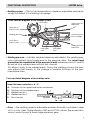
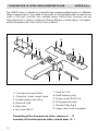
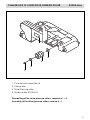
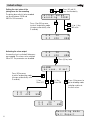
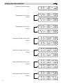
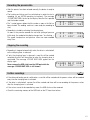
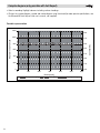
®
GB
OPERATING INSTRUCTIONS
LEISTER Astro
Automatic Wedge Welding Machine
Please read operating instructions carefully before use
and keep it for further reference.
APPLICATION
The LEISTER Astro is an automatic wedge-welding machine for overlap
welding of geomembrane liners in earthwork and civil engineering.
• Thermoplastic geomembrane liners
High-density polyethylene
PE-HD
Low density polyethylene
PE-LD
Chlorinated polyethylene
PE-C
Polypropylene
PP
• Type of seam
Welding seams are produced in accordance
with DVS 2225 part I
Other dimensions are possible on request.
DVS: German Welding Society for welding
LEISTER Process Technologies, Riedstrasse, CH-6060 Sarnen / Switzerland
Tel. + 41 41 662 74 74 Fax + 41 41 662 74 16 www.leister.com [email protected]
WARNING
Danger ! Unplug the tool before opening it as live components and connections are exposed.
Incorrect use of the hot wedge tool can present a fire
and explosion hazard especially near combustible
materials and explosive gases.
Do not touch the element housing and wedge when
hot as they can cause burns. Allow the tool to cool
down. Do not point the hot air flow in the direction of
people or animals.
Connect the tool to a socket outlet with protective
earth conductor. Any interruption of the protective
earth conductor within or outside the tool is dangerous! Use only extensions cables with a protective
earth conductor!
CAUTION
120
230
FI
The voltage rating stated on the tool should correspond
to the mains voltage.
For personal protection, we strongly recommend the
tool be connected to an RCCB (Residual Current Circuit
Breaker) before using it on construction sites.
The tool must be operated under supervision. Radiant
heat from the hot wedge can ignite flammable materials.
Protect the tool from damp and wet.
APPROVAL MARKS
Protection class Ι
TECHNICAL DATA
Voltage
Frequency
Power consumption
Temperature
Welding pressure
Drive
Overlap width
Thickness of material
V~
Hz
W
°C/°F
N/Ibs
m/min./feet
mm/Inch
mm/mil
Noise emission level
Size L × W × H
L pA (dB)
mm
Weight
kg/lbs
2
CCA certified
120, 200, 230 mains voltage is
50 / 60
not reversible
1800
max. 420/788
max. 1500/337
0,8– 5,0/2.6 - 16.5
max. 150/5.9
1,5 – 3,0/60 - 120
70
475 × 355 × 315 with carrying handle /
guide handle (12)
23/50
FUNCTIONAL DESCRIPTION
LEISTER Astro
• Heating system → The hot air temperature is steplessly adjustable and eletronically controlled. It is a floating hot wedge.
Cross-section diagram of hot wedge system
Pinch roller
Upper geomembrane liner
Upper drive /
pressure roller
Welding direction
Fastening screw
for hot wedge
Wedge
Lower drive /
pressure roller
Rear guide
roller
Lower geomembrane liner
Front guide
roller
• Welding pressure → infinitely variable (steplessly adjustable). The welding pressure is transmitted via a toggle lever to the pressure rollers. The swivel head
guarantees the equalization of the pressure to both welded sections (C and D)
as well as on a welded seam without test channel.
This allows T-joints to be welded easily. During the welding process the pressure adjusts itself linearly to the change in material thickness of the geomembrane liners.
Cross sectional diagram of an overlap weld
Seam thickness reduction = A – B
A:
B :
C:
D:
E :
Thickness of the upper and lower membrane
Thickness of the welded seam
C
Welded section 1
Welded section 2
Test channel
D
B
B
A
E
• Drive → The welding speed is adjustable and electronically controlled in steps
of 0.1 m/min / feet. Digital display of SET and ACTUAL values. The power transmission works through a three stage planetary gear.
3
DESCRIPTION OF MACHINE
LEISTER Astro
Frontal view
11
10
5
6
22
1
23
2
24
17 17
3
4
7
15
Side view
12
21
13
4
25 16
18 8 19
20
14
9
DESCRIPTION OF MACHINE
LEISTER Astro
14. Back wheel
15. Foil guide
16. Cable conduit for hot wedge
17. Pinch roller
18. Front guide roller
19. Rear guide roller
20. Lower drive/pressure roller
21. Upper drive/pressure roller
22. Adjustment screw for swivel
head
23. Chain guard of lower part
24. Chain guard of tension arm
25. Chain guard of gear case
1. Mains cable
2. Cable clip
3. Housing of electronics
4. Main switch
5. Display
6. Keyboard
7. Motor/ Drive
8. Hot wedge
9. Lever
10. Adjustment screw for welding
pressure
11. Locking spring of adjustment screw
12. Carrying handle / Guide handle
13. Front wheel
WELDING PARAMETER
LEISTER Astro
10
11
Wedge
ca. 5 mm
Folie
[N] Welding pressure
Illustration A
1500
1375
1250
1125
1000
875
750
625
500
375
250
125
1 2 3 4 5 6 1 2 3 4 5 6
Screen
max. welding pressure 1500 N
Welding pressure
Engage and position the
automatic welding machine
onto the material to be welded. Insert the two geomembranes liners or films about
5mm at the back of the
machine. Pull the lever (9).
The hot wedge is automatically pushed forward. Push
and hold down the locking
spring (11). Turn the adjustment screw for welding pressure (10) until the drive/pressure rollers (20/21) slightly
touch the material to be welded. Let go the locking
spring (11) and release the
tension of the lever (9).
Keep pushing the locking
spring of the adjustment screw
(11). Adjust the welding pressure by turning the corresponding adjustment screw (10)
according to illustration A and
let go the locking spring (11)
at the requested welding pressure.
Warning:
If the maximum welding pressure of 1500N is exceeded
mechanical damage may
occur.
5
WELDING PARAMETERS
LEISTER Astro
Welding temperature
Set the welding temperature with the H , – + keys. The temperature is
dependent on the material and the ambient temperature. The in-put SET value
will be shown on the display. Switch on the heating by pressing the H and
+ keys simultaneously. Heating up time approx. 5 mins.
Heating
cursor will blink on
the display
H
–
H
&
+
+
SET value setting
ON/OFF
Welding Speed
According on the film or geomembrane liner and the influence of the weather,
set the welding speed with the – + keys. The in-put SET value will be shown
on the display.
Drive
–
M
+
SET value setting
ON/OFF
WELDING
LEISTER Astro
Welding preparation
– Laying
Width of overlap is about 80mm to 130mm
– Mains supply
– Cable to mains
Geomembrane liners must be clean between
the overlap as well as above and below.
At least 3kW (generator) supplied with an RCCB
A minimum cable cross section in accordance
with the table.
200 – 230 V~ to
to
120 V~ to
to
6
50 m
100 m
50 m
100 m
3 x1,0 mm2
3 x2,5 mm2
3 x1,5 mm2
3 x2,5 mm2
WELDING
LEISTER Astro
Operating conditions
• Connect the hot wedge-welding machine to the mains
• Start the machine with Main- or Control Level
1
3
5
Main – Level
Main Switch (4) ON
1.
2.
3.
4.
5.
Speed
Speed
Temperature
Temperature
Voltage display
Control – Level
ACTUAL value
SET value
ACTUAL value
SET value
ACTUAL value
–
&
+
2
4
1
3
2
4
5
&
Main Switch (4) ON
1.
2.
3.
4.
5.
Speed
Speed
Temperature
Temperature
Voltage display
*<
ACTUAL value
SET value
ACTUAL value
SET value
ACTUAL value
6
Heating / Drive active
Overload indication
Check the welding process and identify faults by means of the display of power
consumption.
Display (4)
Heating reason for fault
100 %
• mains under-voltage
Display (2)
Drive reason for fault
100 %
100 %
100 %
100 %
100 %
• mains under-voltage
• overlap of the geomembrane liner too wide
• dirt on the drive rollers (20/21)
• max. welding pressure (1500 N) has been exceeded
• high welding speed with large sudden overload
(ie anchoring trench, T-joints....)
or
or
or
or
<
<
<
<
after heating up time
If malfunction does not disappear, contact service center
7
WELDING
LEISTER Astro
Welding procedure
• Check:
– Drive/ Pressure rollers (20/21) as well as the hot wedge (8) must
be clean before engaging into the geomembrane liner or film.
– Cable length/Cable guide.
• Adjust welding parameters, see page 5/6.
• The welding temperature must be achieved.
• Guide and position the automatic welding machine into the over-lapped
geomembrane liner or film.
• Switch on drive motor with M key on keyboard (6).
• Pull the lever (9).
Beginning of welding process
• Check the welded seam (wash/seam thickness reduction). As required,
adjust the welding speed with – + keys on keyboard (6).
• The automatic welding machine is guided along the overlap with the carrying
handle/guide handle (12), so that the frontal width of the overlap is kept within
the 22mm zone (see illustration B).
Illustration B
21
15
23
Dim. of pressure roller 50mm
Dim. of pressure roller 45mm
22mm
24.5mm
Max. frontal width of
overlap.
End of welding process
• Release the tension lever (9) 1 cm before the end of the welded seam.
• Switch off the drive motor with key M on the keyboard (6). Switch off the heating by pressing the H and + keys on the keyboard (6) simultaneously.
8
ADJUSTING THE HOT WEDGE
LEISTER Astro
Adjusting of the guide rollers for the requested material thickness
• Engage the automatic wedge-welding machine on the geomembrane liner
or film to be welded.
• Stretch the lever (9)
• Loosen the hexagon cap screw of the rear guide roller (19).
• The distance between the hot wedge (8) and the rear guide roller (19) should
be the thickness of the material and the sharp tongue of the wedge should lie
centrically to the pressure rollers (20/21).
• Tighten the hexagon cap screw of the rear guide roller (19).
• Loosen the hexagon cap screw of the front guide roller (18).
• The distance between hot wedge (8) and front guide roller (18) should be
about 1 mm.
• Tighten the hexagon cap screw of the front guide roller (18).
Cross-section diagram of hot wedge system
21
20
8
19
18
9
CHANGEOVER OF UPPER DRIVE/PRESSURE ROLLER
LEISTER Astro
The LEISTER Astro is suitable to manufacture overlap-welded seams in different
fields of applications. They differ in the width of the welded seam as well as the
width of the test channel. Also welded seams without test channel can be
manufactured. In order to implement these different overlap seams, the appropriate drive/pressure rollers have to be installed.
1
2
12
4
11
5
10
9
8
3
6
6
7
1. Countersunk screw M3×6
7. Shaft 8×118.5
2. Protection sheet swivel head
8. Shaft retaining ring
3. Socket head screw M4×8
9. Distance disk 20×32×0.5
4. Washer 4.2×25
10. Drive/pressure roller
5. Slide roller
11. Woodruff key 5×6.5
6. Set screw M5×12
12. Upper drive shaft complete
Dismantling of the drive/pressure rollers, sequence 1 – 12
Assembly of the drive/pressure rollers, reverse order 12 – 1
10
CHANGEOVER OF LOWER DRIVE/PRESSURE ROLLER
LEISTER Astro
4
4
3
2
1
1. Countersunk screw M5×16
2. Clamp disk
3. Drive/Pressure roller
4. Distance disk 20×32×0.5
Dismantling of the drive/pressure rollers, sequence 1 – 4
Assembly of the drive/pressure rollers, reverse 4 – 1
11
®
BA Astro/05.2002/GB
TRAINING
LEISTER Process Technologies and their authorised Service Centres offer free
welding courses and training.
ACCESSORIES
• Only LEISTER accessories should be used.
MAINTENANCE
• Check mains cable (1) and plug for electrical and mechanical damage.
• Clean hot wedge (8) with a copper brush.
• Clean drive and pressure rollers (20/21) with a wire brush.
• Treat chain (22) with a suitable spray as required (chain guard 23/24).
• Check whether rollers (13/14/17/18/19) are running smoothly.
SERVICE AND REPAIR
• The tool should be checked by an authorized Service Center if the following
message appears on the display (5): «maintenance; servicing».
• Repairs have to be carried out by authorised LEISTER Service Centres only. They
guarantee a specialized and reliable repair service within 24 hours using
original LEISTER spare parts.
GUARANTEE AND LIABILITY
• Guarantee and liability are in accordance with the guarantee certificate as
well as with the currently valid general business and sales conditions.
• LEISTER Process Technologies rejects any guarantee claims for tools which are
not in their original condition. The tools must never be altered or changed.
Technical data and specifications are subject to change without prior notice.
Your authorized Service Centre is:
LEISTER Process Technologies, Riedstrasse, CH-6060 Sarnen / Switzerland
Tel. + 41 41 662 74 74 Fax + 41 41 662 74 16 www.leister.com [email protected]
GB
Operating instructions (Translation of the original operating instructions)
Please read operating instructions carefully before use and keep for future reference.
Please keep the operating instructions to hand when operating the COMET hotwedge welding machine.
USB port (optional)
Attachment for the Leister ASTRO hot-wedge welding machine
Application
The USB port enables the process values temperature, speed and pressure to be recorded on a standard USB stick.
The assessment is made using spreadsheet software, not supplied, e.g. Microsoft® Excel.
Basic information regarding the USB stick
• Never remove the USB stick from the USB port while saving! The data will not be saved! Always finish recording welding in accordance with the operating instructions.
• If a new USB stick is used, this should be formatted in format FAT 32 with memory size 512 bytes.
• Important: Always test new USB sticks on the device! Sometimes not all USB sticks work with the device.
This can depend on USB copies or on preinstalled software which wants to start up automatically, for example, etc.
Date and time
• Set up or check the date and time the first time that the device is started up. You can find the instructions for
this under the heading Presettings (diagram).
• The date and time are powered by a battery independent of the power supply.
It is recommended to check its function periodically.
Inserting USB stick
• Unscrew protective cover
• Insert USB stick in the USB port
• Screw the protective cover back on
• «USB» appears at the bottom right of the machine’s display
Without the USB stick, the mains voltage is displayed at the bottom right.
0.0
3.2
20
420
3.2
3.2*
20
420*
0
USB
File name
• A file name consisting of the current date (month and day) and the
file number will be created automatically when recording is started.
Example 0309-002 fi 09. March, second recording.
• The file number increases automatically every time it is saved.
The number begins again at 001 every day.
10
1000
002
➝
Presettings
To set date, edit client text or display of operating hours counter.
By pressing keys – and + at the same time, the following display appears:
&
–
Da t e / Te x t
S h ow T i me r
–
+
- >+
->-
+
Se t Da t e
S h ow T e x t
(M) ––3O ( H )
–––8 : 10–––30 : 10
- >+
->-
Changes automatically to operating
mode after 3 seconds
+
–
C OM P A N Y
( M ) = E d i t , ( H ) =O k
T i me :
Da t e :
14 07 : 43
16 . 02 . 10
M
A
( - ) (+)
+
( H ) =E n t e r
+
–
H
–
(+) or (-) key:
select symbol
(H) key:
continue to next
symbol
(H) key:
Existing text is
accepted.
H
Return to
operating mode
M back to previous
(+) or (-) key:
edit value before the cursor
H
(H) key:
move cursor to next value
M
(M) key:
return to operating mode
(M) key:
symbol
Finish: Enter a «space» as the last character. Confirm with
the (H) key. The text may be a maximum of 16 characters long.
F I RMA X Y
Tex t Ok?
( H ) =O k
H
0.0
3.2
20
420
0
USB
Operating mode display
11
Default settings
Setting the start value of the
joining force for the recording
M
The joining force which is to be recorded
can be set between 100 N and
500 N in 5 N increments
&
H
i n i t i a l va l ue
r eco r d i ng
200N
H
Press (H) or (M) key once,
to return to operating mode
(changes automatically after
3 seconds)
Activating the alarm output
An acoustic alarm is activated if tolerances
are exceeded. This alarm can be switched
ON or OFF. The parameters can be edited.
0.0
3.2
20
420
+
–
0.0
3.2
20
420
0
USB
0.0
3.2
20
420
0
USB
H
A L A RM
- no , +y e s ,
Press (M) key once,
to return to operating mode
(changes automatically after
3 seconds).
Press (M) and (H)
keys simultaneously
(+) or (-) key
Edit value
Press (H) key twice
H set
M
(-) key
Alarm OFF
–
+
(+) key
Alarm ON
H
Press (H) key once, to
go to recording mode
selection and to set
the limit values.
0
USB
0.0
3.2
0
20 ×
420
USB
R e c o r d i n g mo d e
Fu l l Repo r t
12
Default settings
0.0
3.2
20
420
H
Select recording mode
0
USB
Press (H) key three times,
to set the limit values
R e c o r d i n g mo d e
Fu l l Repo r t
• Short Report
Record only if parameters are
outside the set limit values
+
• Long Report
Recording every 5 cm
H
–
(+) or (-) key
Toggle between
Full Report or
Short Report
l imi t se t t i ng
400°C
T e mp . –m i n
+
H
–
Set limit values for alarm output
If the effective value is outside the set limit
values, the acoustic alarm will be activated.
(+) or (-) key
Edit values
l imi t se t t i ng
450°C
T e mp . –m a x
H
l imi t se t t i ng
1000N
F o r c e –m i n
(M) key:
Return to operating mode
(changes automatically
after 3 seconds)
M
H
l imi t se t t i ng
1250N
F o r c e –m a x
H
l imi t se t t i ng
5 cm
Speed +/ 0.0
3.2
20
420
H
0
USB
13
Display when alarm activated
Display when alarm activated
Speed below the limit value
0.0
3.2
20 ×
0
420
USB
va l ue
3.2*
420 ×1000
420* ➝002
v <
3.2*
420 ×1000
420* ➝002
va l ue
3.2*
420 ×1000
420* ➝002
v >
3.2*
420 ×1000
➝002
420
flashing
Speed above the limit value
flashing
Temperature below the limit value
3 . 2 v a l u e×1000
3 . 2 * 420* ➝002
flashing
3.2
3.2*
Temperature above the limit value
t < ×1000
420* ➝002
3 . 2 v a l u e×1000
3 . 2 * 420* ➝002
flashing
Joining force below the limit value
3.2
3.2*
t > ×1000
420* ➝002
3.2
3.2*
420 va l ue
420* ➝002
3.2
3.2*
420
420*
3.2
3.2*
420 va l ue
420* ➝002
3.2
3.2*
420
420*
flashing
Joining force above the limit value
F <
002
➝
flashing
14
F >
002
➝
Recording the process data
• After the presets have been entered correctly, the device is ready to
record.
• The heating and drive must be switched on in order to start a
recording (as per ASTRO operating instructions). The message
«PLEASE WAIT USB» flashes on the display. Now the file is opened
and the header created
• The * symbol appears before the file number as soon as the file has
been created. The welding machine is now ready for recording to
start.
• Recording is started by activating the clamping lever.
As soon as the pressure exceeds the set value (setting of pressure
initial value), the symbol on the display changes from * to a flashing ➝.
The speed, temperature and pressure values are now recorded
every 5 cm.
P L E A S E WA I T U S B
3 . 2* 420* - - - 3.2
3.2*
420
420*
0
* 002
3.2
3.2*
420
420*
➝
1000
002
Stopping the recording
• Recording is stopped automatically when the drive is switched off
or the clamping lever is released.
• If only the clamping lever is released, a new file will be created
automatically which will be written to when the clamping lever is
reactivated. The message «PLEASE WAIT USB» appears on the
display again
Never remove the USB stick from the USB port while the
message «PLEASE WAIT USB» is still shown!
P L E A S E WA I T U S B
3 . 2* 420* - - - -
Further recordings
• If the drive and heating remain switched on, a new file will be created and the process values will be recorded
every time the clamping lever is activated.
• If the drive is switched off, no new file will be created and there will be no recording of the process values
after the clamping lever is activated.
• If the values are not to be recorded any more, the USB stick must be removed
• Check the remaining memory of the USB stick on the PC from time to time.
15
Evaluation
• Insert USB stick into USB port of a computer (not supplied).
• Start spreadsheet software (not supplied).
• Open file
• Select drive (drive with USB stick)
• File type: «all files»
• Select and open the desired recorded file (*.csv)
• The file opens. Example of file content:
Full-Report
Client text (can be edited)
COMPANY
Number of recording file
File-number:
0825-002
LEISTER Switzerland
ASTRO
Software Release 3.1A USB
Recording interval
Start value for recording
Alarm switched off
Serial number:
Date:
Time:
v=
t=
intervall =
initial value =
Alarm =
Column headings
Unit
Distance
[cm]
1. Record
another record every 5cm
0
5
10
15
20
25
30
35
40
45
50
55
60
65
70
75
80
85
90
95
100
Serial number:ASTRO
Header
Data
16
715092
25.08.2010
16:02:16
2.5 m/min
380 °C
5 cm
350 N
OFF
Speed Temperature
v[m/min]
t[°C]
2.5
2.5
2.5
2.5
2.5
2.5
2.5
2.5
2.5
2.5
2.5
2.5
2.5
2.5
2.5
2.5
2.5
2.5
2.5
2.5
2.5
380
380
380
380
380
380
380
380
380
380
380
380
380
380
380
380
380
380
380
380
380
Force
F[N]
1015
1015
1015
1015
1015
1015
1015
1015
1015
1015
1015
1015
1015
1015
1015
1015
1015
1015
1015
1015
1015
16
Evaluation
Short Report
Header
Client text (can be edited)
COMPANY
Number of recording file
File-number:
0826-003
LEISTER Switzerland
ASTRO
Software Release 3.1A USB
Serial number ASTRO
Recording interval
Start value for recording
Alarm switched on
Alarm limit values
Serial number:
Date:
Time:
v=
t=
intervall =
initial value =
Alarm =
Limit setting
Lower limit temp. =
Upper limit temp. =
Lower limit force =
Upper limit force =
Tolerance speed =
715092
26.08.2010
08:02:28
2.7 m/min
380 °C
5 cm
350 N
ON
350 °C
450 °C
800 N
1200 N
5 cm
Data
Column headings
Distance
Speed
Temperature
Force
[cm]
v [m/min]
t [°C]
F [N]
Unit
Deviations from the limit values
are logged (only if alarm is
active)
No limit value deviations
Summary
Column headings
Unit
Summary of the welding para
meters at the end of the seam
Seam length
[m]
5
v min
v max
[m/min] [m/min]
2.7
2.7
t min
t max
F min
F max
[°C]
[°C]
[N]
[N]
380
380
1015
1015
If a parameter is outside the set limit values, this will be logged (only if alarm is switched on). At the end of the
recording a summary of the welding is logged.
17
Compile diagram (only possible with Full Report)
• Select a recording. Highlight columns including «column headings».
• Click on the «create diagram» symbol and create diagram using the wizard (for more precise specifications, see
the Microsoft® Excel help or Excel user’s manual, not supplied).
Possible representation
1200
2.90
2.70
800
2.50
2.30
600
2.10
400
1.90
200
1.70
0
1.50
0
100
200
300
400
500
Distance [cm]
Temperature [°C]
18
Force [N]
Speed [m/min]
600
Speed [m/min]
Temperature [°C] / Force [N]
1000
19
®
© Copyright by Leister
Leister Process Technologies
Galileo-Strasse 10
CH-6056 Kaegiswil/Switzerland
Tel.
+41 41 662 74 74
Fax
+41 41 662 74 16
www.leister.com
[email protected]
20
Anhang zu BA ASTRO
141.158 GER / ENG /BA USB-Port / 11.2010
Your authorised Service Centre is: