1
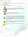
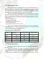
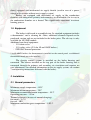
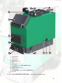
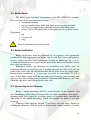
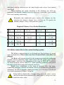
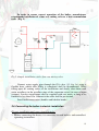
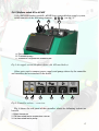
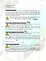
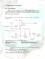
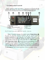
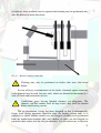
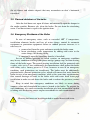
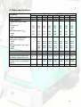
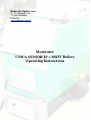
Moderator Spółka z o.o.
Ul. 11 Listopada 16a
17-200 Hajnówka
POLAND
www.moderator.com.pl
Moderator
UNICA SENSOR 10 ÷ 60kW Boilers
Operating Instructions
TABLE OF CONTENTS
Dear User, ............................................................................................................................... 3
1. Overview ............................................................................................................................ 3
1.1. Safety Instructions ........................................................................................................... 3
1.2. Warranty Terms and Conditions .................................................................................... 5
1.3. Fuel .................................................................................................................................. 6
1.3.1. Burning Other Fuels ..................................................................................................... 7
1.4. Technical Description ..................................................................................................... 7
1.5. Equipment ....................................................................................................................... 8
2. Installation .......................................................................................................................... 8
2.1. General parameters .......................................................................................................... 8
2.2. Boiler Room .................................................................................................................. 11
2.3. Boiler Installation .......................................................................................................... 11
2.4. Connecting to the Chimney ........................................................................................... 11
2.5. Boiler connection to the central heating system............................................................ 12
2.6 Connecting the boiler to electric installation.................................................................. 13
2.7. Protection of the Installation ......................................................................................... 19
2.7.1. Open systems.............................................................................................................. 19
2.7.2. Closed Systems .......................................................................................................... 20
2.7.3. Thermal protection ..................................................................................................... 22
3. Boiler operation ................................................................................................................ 23
3.1. Controller – description, operation, servicing ............................................................... 23
3.2. Igniting .......................................................................................................................... 25
3.3. Burning .......................................................................................................................... 25
3.4. Boiler and Chimney Cleaning ....................................................................................... 26
3.5. Planned shutdown of the boiler ..................................................................................... 28
3.6. Emergency Shutdown of the Boiler .............................................................................. 28
4. Boiler Troubleshooting .................................................................................................... 29
4.1. Maintenance and overhauls ........................................................................................... 29
5. Safe operation conditions ................................................................................................. 29
6. Disposal ............................................................................................................................ 31
7. Connecting the boiler to automatic feeders ...................................................................... 31
7.1. The boiler may be used with Automatic Biomass Burning Feeders “Smok” ŻL and
GC ........................................................................................................................................ 31
7.2. Boilers intended for pellets burners .............................................................................. 32
8. Boiler specifications ......................................................................................................... 33
Due to on-going research & development work, the manufacturer
reserves the right to make boiler design and documentation
changes. Consequently certain elements of the boiler, as presented
on photographs or drawings in these instructions may differ from
elements as in delivered unit.
2
Dear User,
Thank you for your purchase of our equipment and congratulations on
your good choice.
Moderator Spółka z o. o. has been manufacturing boilers utilizing
proprietary technological solutions developed in late 70’s in Hajnówka by
engineer Mr Kazimierz Kubacki. For almost thirty years these boilers have been
undergoing multiple technological changes and upgrades. This instruction
manual is based on the latest information of the manufacturer. Due to ongoing
development works on the boiler the manual is only applicable for the boiler it is
delivered with.
Moderator boilers are intended for heating water up to maximum
temperature of 90 degrees Celsius in central-heating and hot household water
installations as well as in process installations (wood dryers, presses, etc.).
This manual has been designed to assist users in boiler installation,
operation, maintenance and servicing. It shall be read and understood before
commencing with these activities.
1. Overview
1.1. Safety Instructions
The main condition of safe boiler operation is its correct connection to the
central heating installation. The manufacturer has undertaken all efforts to
ensure safe operation of the device. This will only be possible after all
connection and operation requirements discussed in these instructions are met
and complied with. Failure to perform any action, due to involved costs of
additional equipment installation will certainly affect the safety or cause the
equipment operating costs to raise in future.
All performance tests and trials of boilers have been performed using
carefully selected accessories (safety valves, thermal protections) and equipment
(air supply systems). In order to guarantee maintenance of declared high
performance of the boiler, manufacturer-recommended equipment must be used
exclusively.
We would like to hereby advise against using substitute solutions,
which have not been checked with that boiler and which do not have required
approvals (Technical Supervision Office - UDT) and certificates (declaration
of conformity, CE sign). We also advise against any unauthorized changes in
the boiler design.
Failure to follow these recommendations may lead to serious threats and
expose the operating personnel to health or life hazard.
3
In case of doubt, please consult our sales department or authorized
servicing agent.
Safety and Warning Signs
Note: The washout located under the masking cover may be hot.
Pay special attention in the boiler room, as other parts of the boiler
and the installation may also be hot..
This sign in this manual indicates a danger.
Please carefully read the corresponding section so as to avoid
dangerous situations in future.
Keep in mind that in the boiler room various surfaces may have
different temperatures. You have to pay special attention to the fact,
that temperature of doors may be significantly higher than the
temperature of other boiler surfaces. This also applies to the smoke
breeching and supply and return piping. When in boiler room, always
pay special attention.
Keep in mind that ashes and fuel (in particular dry sawdust and
chips) may cause allergic reactions. We recommend wearing
protective gloves and dust masks.
Keep the boiler room clean. Fuel left or spilled on the floor may
cause a fire.
4
1.2. Warranty Terms and Conditions
1.
2.
3.
4.
5.
6.
7.
Manufacturer grants 36-month warranty for the unit, which covers all
workmanship and material faults.
Manufacturer warrants fault-free operation of the central heating, which is
further attested by the production plant’s seal.
Manufacturer requires the guidelines below to be followed:
• the first starting of the unit shall be performed by the manufacture’s
technical support representative
The warranty shall not include damages resulting from misuse or normal
wear and tear, refund of assembly costs, travel costs, damages resulting
from modifications or repairs implemented or performed without
manufacturer’s consent, indirect and consequential damages, production
outage related losses or any other economic loses co caused.
The warranty shall not include faults resulting from:
• failure to follow assembly guidelines stated in these operating
instructions or resulting from regulations currently in force,
• incorrect servicing or maintenance or effects of boiler operation in a
way, which is incompatible with its operating instructions’ provisions
(use of incorrect fuel, leaving ash after the heating season, faults
resulting from central heating installation freezing, incorrect or blocked
flue system, loss of water in the installation)
• utilization of the boiler for purposes other than its intended use, as
specified in the operating instructions
• in case of incorrect selection of the boiler output to the object’s heat
demand
All warranty claims must always be sent to the boiler seller. Before
submitting a claim, please make ready the following details:
• photocopy of page 5 of the operating instructions, item 1.2. (with
entered date and legible signature of the user)
• description of the fault
• a document to prove the equipment purchase
• boiler rated power
• serial number
User statement:
I hereby declare to have acknowledged myself with the Moderator boiler operating instructions and I hereby confirm
that the equipment was delivered as ordered, new, complete and technically operational. Above that a specialized
company presented to me principles of the equipment operation and provided a complete set of documentation. I
hereby accept the Moderator boiler manufacturer’s recommendations. In case of an unjustified service request to the
Moderator company under a warranty repair, I undertake to bear all related costs (man hours and costs of shipping to
and from the service centre) up to their full amount.
Date, company name or first and last name
legible signature
5
Declaration of Conformity
We,
Moderator Spółka z o.o.
Ul. 11 Listopada 16a
17-200 Hajnówka, POLAND
tel. +48 (0)85 682 75 20
hereby declare under our own and sole responsibility that the product: MODERATOR
central-heating boiler, serial nos. from 400, to which this declaration applies, meets the
following requirements and standards, as applicable:
Directives
97/23/WE
Standards
EN-PN- 303-5
Hajnówka, on 2004.02.01
1.3. Fuel
Use only fuels recommended by the manufacturer.
The Moderator boiler is designed to burn renewable fuels, wood-based
and vegetable fuels (pieced wood, chips, sawdust, bark) with moisture content of
up to 30%. Coal may be used as a substitute fuel
Technical parameters of the boiler are specified for fuels with humidity
content of up to 30% and calorific value of Q=17.084 kJ/kg for wood and
Q=29.924 kJ/kg for coal.
The higher the moisture content, the lower the calorific value (note: an
increase of moisture content causes calorific value to drop, which means that
one will need twice as much fuel to achieve the same heating effect).
A considerable part of thermal energy is wasted in the burning process for
heating up the fuel and evaporating water (note: using wet fuel directly
contributes to shortening of boiler’s operational life and causes it to wear out
prematurely).
Hygrometers are used for moisture content measurements (different types
are used for sawdust and different for wood) and these are necessary equipment,
which should be used when purchasing fuel (to check the actual moisture
content) as well as during normal operation of the boiler.
6
1.3.1. Burning Other Fuels
Uncontaminated paper and cardboard may only be used for igniting fire in
the boiler. Mixtures of various clean paper and cardboard may only be burned
with wood. Papers and magazines must not be burned and should be recycled.
One shall keep in mind that impregnates, inks and other components used for
their production will significantly pollute the natural environment.
We also advise against burning plastics in various forms. Keep in mind
that smoke generated during combustion of plastics will contain substances,
which are poisonous and harmful to human and that these substances will fall
down in direct vicinity of the chimney. Do not burn PVC products under any
circumstances, e.g.:
- butter or margarine boxes
- transparent plastic bottles
- jewel boxes (cassettes/CDs) or toys
- plastic building materials
- polyamide (PA) products, such as textiles
Some plastics identified as PE, PP, PET may be burned, provided that
their volume does not exceed 5% of the fuel volume (e.g. of wood) and the
combustion temperature is not lower than 850o C.
Approximate data of different fuels
Fuel type
wood
pieces
chips
sawdust
bark
coal
Burning time
( h)
4-6
3-5
2-4
2-5
6-8
1 cubic meter weight
( kg )
404
215
238
250
900
moisture content
(%)
15
15
15
15
-
1.4. Technical Description
This manual applies to boilers rated from 10 to 60 kW manufactured in
the plate version.
Moderator boilers (Fig. 1) are boilers operating in the top-burning system.
Walls and grate are water cooled (the version supporting burners may be
equipped with cast iron grate) and made of quality sheet metal plates. Manual,
top fuel charging, mechanical ash removal from the grate, bottom doors (ash pan
7
doors) equipped with mechanical air supply throttle (used in case of a power
outage or in versions without an air supply system).
Boilers are equipped with directional air supply to the combustion
chamber with autogenous primary and secondary air distribution. On its way to
the combustion chamber air is heated. This significantly contributes to correct
burning process.
1.5. Equipment
The boiler is delivered in assembled state. Its standard equipment includes
a thermometer* and a cleaning kit. Other, additional elements depend on the
purchased version and are not included in the boiler price. The ash tray is only
available for 10-25kW models.
Additional non-fixed equipment:
- G ½ drain valve
- G ¾ safety valve (G ½ for 10 and 15kW boilers )
- SYR 5067 thermal protection
* in 40-60kW boilers, the thermometer is installed on the control panel, so additional
thermometer needs not to be installed.
The electric control system is installed on the boiler housing and
connected. The blower installed on the top part of the boiler housing and is
connected through the primary and secondary air circulation and requires no
user adjustments (for detailed information on the air supply system, see section
7 and operating instructions delivered with the boiler).
2. Installation
2.1. General parameters
Maximum supply temperature – 90˚C
Maximum return temperature – 70˚C
Minimum recommended return temperature – 55˚C
Operating pressure - 1.5 bar
Thermal efficiency (in case of manual charging):
for wood – 78.7%
for coal - 80%
Minimum combustion gases temperature – 150o C
8
8
13
12
9
6
1
2
3
5
4
1.
2.
3.
4.
5.
6.
7.
8.
9.
10.
11.
12.
13.
11 7
10
Charging flap
Grate doors
Ash-pan doors
Air throttle
Mobile grate lever
Fan
Return pipe
Top washout cover (20 and 25kW boilers)
Supply pipe
Ash pan washout cover
Straight-through valve G½ muff
Tech ST-81 controller (10 to 30kW boilers)
G½ muff
Fig.1a. Unica SENSOR 25 kW boiler – description of main parts.
9
8
9
12
13
6
1
2
3
5
4
1.
2.
3.
4.
5.
6.
7.
8.
9.
10.
11.
12.
13.
11 7
10
Charging flap
Grate doors
Ash-pan doors
Air throttle
Mobile grate lever
Fan
Return pipe
Top washout cover (20 to 60kW boilers)
Supply pipe
Ash pan washout cover
Thermometer
ecoMAX 200 controller (40 to 60kW boilers)
G½ muff
Fig.1b. Unica SENSOR 50 kW boiler – description of main parts
10
2.2. Boiler Room
The boiler room shall meet requirements of the PN-87/B-02411 standard.
Here are some of the most important of them:
• waterproof flooring
• steel or wooden doors lined with sheet metal, opening outwards
• 21x21 cm air supply hole in the bottom part of the boiler room
• at least 14x14 cm exhaust hole in the upper part of the boiler room
Equipment:
• tap
• sewage well
• sing
Forced ventilation must not be used.
2.3. Boiler Installation
Boiler installation shall be performed by an engineer with appropriate
qualifications and experience (we advice you to seek help from representative
centres, whose installers have undergone training in Moderator Sp. z o.o.).
A faulty installation may cause premature wear of the boiler and threatens fire or
may cause an explosion.
Moderator boilers are delivered in assembled state. Boiler may be
positioned directly on the floor with 1 gradient towards the front wall (the top
point of the boiler after the installation shall be the place close the supply pipe).
During boiler installation, it is necessary to ensure its accessibility in such a
way, so that boiler room walls do not render fuel charging, grate cleaning and
access to the side washout and fan difficult. Recommended distances are: min.
80cm for side walls and 100 cm for the front wall.
2.4. Connecting to the Chimney
Boiler’s smoke breeching shall be seated directly in the chimney, and
after installation sealed along the contact line of: smoke breeching sheet metal –
chimney brick. It is necessary to ensure access to washout doors installed on
side walls of the smoke breeching, which are intended for boiler’s rear part
cleaning.
Chimney outlet shall be located 75 cm above the roof ridge. Square or
rectangular chimneys shall be made of burnt brick; round chimneys (usually
11
steel ones) shall be insulated over the whole height with at least 5-cm mineral
wool layer.
When installing the smoke breeching in the chimney, one shall pay
attention to the chimney damper lever (it is necessary to provide a space needed
for its easy opening and closing).
Remember that combustion gases entering the chimney are hot,
therefore the chimney damper lever will heat up. To operate the
chimney damper, always wear protective gloves.
Required Chimney Cross-Section Dimensions
Power
kW
square chimney rectangular chimney round chimney chimney height
cm x cm
cm x cm
diameter (cm)
(m)
up to 15
18 x 18
14 x 27
18
6÷8
20 ÷ 32
20 x 20
14 x 27
24
8 ÷ 10
40 ÷ 50
25 x 25
-
28
8 ÷ 10
60 ÷ 150
30 x 30
-
35
8 ÷ 10
2.5. Boiler connection to the central heating system
The boiler is manufactured as an all-round unit that facilitates of various
types of connections. Please make sure that all unused holes and outlets are
plugged.
The Boiler will operate correctly if the temperature inside the combustion
chamber will be sufficiently high, which means that the supply water (on the
boiler output ) shall have the temperature in the range of 70 to 80O C, and that
the water on return, not less than 55O C. Such operating parameters will protect
the boiler against low-temperature material corrosion.
Boilers have connections in the form of threaded G1½ stub pipes.
Connecting stub pipes with the installation shall be performed using appropriate
connectors. In order to properly connect the boiler, it is necessary to install all
accessories presented on Figures 1a and 1b.
If the boiler is fitted with a thermal safety valve, the valve’s sensor
shall be installed in the dedicated G½ muff (item 13 on fig.1a,b), then
install the safety valve.
12
In order to ensure correct operation of the boiler, manufacturer
recommends installation of a four-way mixing valve or a heat accumulation
tank. (Fig. 2)
Pompa CWU – Hot houtehold water pump
Pompa M – M Pump
Fig.2. Sample installation with a four-way mixing valve.
Connect water supply pipe through the G½ valve (11, fig. 1a) using a
flexible hose, which after filling is completed shall be disconnected. When
filling open all venting valves in the installation and slowly close them until
water overflows in the overflow pipe of the expansion vessel (in case of open
systems). Lossless installations may be supplied with raw water, as long as its
hardness is less than 10 n. Otherwise the water shall be pre-treated.
Install boiler accessories (handles and bakelite knobs ).
2.6 Connecting the boiler to electric installation
Electric installation and connection principles.
1. Before connecting the device, it is necessary to read boiler’s and controller’s
operating instructions.
13
2. Before commencing with assembly, repair or maintenance works and when
performing all connections, it is necessary to disconnect power supply from
the device and verify that power lines are disconnected from mains.
3. Boiler house shall be equipped with 230V/50Hz electric installation,
compatible with relevant regulations applicable in this scope.
4. The electric installation (regardless of its type) shall be terminated with a
power receptacle equipped with a protective earth terminal. Use of power
receptacles without properly wired protective earth terminal will
constitute electric shock hazard!!!
5. The boiler shall be connected to a separately installed power supply line,
protected with suitably chosen fast-blow fuse and differential-current circuit
breaker (shock protection). The value and the type of the fuse is defined in
the controller’s operational documentation. No other equipment must be
connected to this line.
6. The box, in which electric accessories are contained, may only be opened by a
competent electric engineer, knowledgeable with the equipment operation.
7. Location of the power receptacle used for the boiler connection shall be
selected in such a way so that the plug is easily accessible to allow quick
boiler disconnection in case of an emergency.
8. Wires shall be routed away from the parts of the boiler that may get hot, and
in particular away from hot elements of the flue breeching.
9. The controller must not be exposed to flooding or to conditions causing
vapour condensation, e.g. rapid ambient temperature changes.
10.The controller must not be operated if its enclosure is damaged.
11.Protect the controller against access of children.
12.During thunderstorms, the controller shall be disconnected from mains.
2.6.1 Boilers rated 10 to 30 kW
Unica SENSOR boilers rated 10 to 30 kW have preinstalled air supply
system, which consists of the following elements:. A B C (ref. fig. 3).
Other parts used to connect power supply and pumps driven by the controller are
located in the box attached to the boiler.
14
A
B
C
A. Blower
B. Connecting cable
C. Tech ST-81 controller
Fig.3. Air supply system (the photo shows a 20 kW rated boiler).
Connecting power supply
The boiler is connected to the power supply network by inserting one end of
the power supply cord (delivered with the boiler) to the electric power supply
receptacle
1 (Fig. 4). The other end, terminated with the power plug must
be inserted into an outlet of the electric power supply installation.
In case of a damage to the power supply cord, replace it with a cord
of the same type.
Connecting central heating circulating pump
This operation shall be performed by a person with necessary
qualifications to perform electric installation works.
Connect the circulating pump to 4 (Fig. 4.) socket, identified as
“POMPA co” using a cable with cross-section of at least 3x0.75mm2 using
suitable socket (included).
15
Connecting domestic hot water pump
This operation shall be performed by a person with necessary
qualifications to perform electric installation works.
The pump used to charge the household hot water tank shall be 2 connected
to the socket (Fig. 4.) identified as “Pompa cwu”, using a cable with crosssection of at least 3x0.75mm2 using suitable socket (included). The household
hot water tank’s temp. sensor 3 shall be connected to the socket located
above the power supply socket.
1. Power supply socket
2. Hot household water
pump socket
3. Household hot water
temperature sensor
socket
4. Central heating pump
socket
5. Fuse
2
1
3
4
5
Fig.4. Tech ST-81 controller – rear view.
16
2.6.2 Boilers rated 40 to 60 kW
Unica SENSOR boilers rated 40 - 60 kW have preinstalled air supply system,
which consists of the following elements: A B C (see fig. 5)..
A
B
C
A. Dmuchawa
B. Przewód łączący
C. Sterownik z regulatorem ecoMAX 200
Fig.5. Air supply system (the photo shows a 40 kW rated boiler).
Other parts used to connect power supply and pumps driven by the controller
are located in the box attached to the boiler.
1
2
3
4
5
6
Fig.6. Controller sockets – rear view.
Fig. 6 shows the real panel of the controller, where the following sockets are
located:
1. Local thermostat
2. Hot household water temperature sensor
3. Hot household water pump
17
4. Central heating pump
5. Air blower
6. Power supply socket
Connecting power supply
The boiler is connected to the power supply network by inserting one end of
the power supply cord (delivered with the boiler) to the socket 6 (Fig.
6.) marked as “230V~ 50Hz”, which is located on the controller enclosure. The
other end, terminated with the power plug must be inserted into an outlet of the
electric power supply installation.
If the power supply cord is damaged, it shall be replaced with a cable
of the same type, with wires’ cross-section of at least 3x0.75mm2.
The maximum, combined loading of 3 4 5
outputs is 3A.
Connecting the central heating circulating pump
This operation shall be performed by a person with necessary
qualifications to perform electric installation works.
The circulating pump shall be connected to 4 socket using a cable with
cross-section of at least 3x0.75mm2. While making the connection, the pump
cable shall be terminated with a computer-type plug (included).
Connecting the hot household water pump
This operation shall be performed by a person with necessary
qualifications to perform electric installation works.
The pump that charges the hot household water tank shall be connected to the
socket, 3 using a cable with cross-section of at least 3x0.75mm2. While
making the connection, the pump cable shall be terminated with a computer-type
plug (included). Temperature sensor of the hot household water tank shall be
2
connected to input no. .
Connecting the local thermostat
This operation shall be performed by a person with necessary
qualifications to perform electric installation works.
The local thermostat shall be connected to socket 1 of
the
controller, terminating its cable with a RCA plug (included with the boiler).
Operation of the controller when fitted with the local thermostat is described in
the PLUM ecoMAX 200 controller documentation.
18
2.7. Protection of the Installation
2.7.1. Open systems
Moderator boilers operating in open central heating systems must be
connected according to requirements of the PN-91/B-02413 standard, so that
excess heat in the form of steam shall be removed through an open connection
(RP overflow pipe) to atmosphere
Fig.7. Installation protection for boilers operated in open central-heating
installations
KOMIN – CHIMNEY
CZUJNIK TEMPERATURY – TEMPERATURE SENSOR
STEROWNIK – CONTROLLER
ZAWÓR SPUSTOWY – DRAINAGE VALVE
ZAWÓR MIESZAJĄCY– MIXING VALVE
WĘŻOWNICA - COIL
ZASILANIE Z SIECI - WATER PIPE SUPPLY
ZAWÓR BEZPIECZEŃSTWA - SAFETY VALVE
KOCIOŁ – BOILER
WENTYLATOR – BLOWER
NACZYNIE WZBIORCZE – PRESSURE VESSEL
ZBIORNIK AKUMULACYJNY – HEAT ACCUMULATION TANK
INSTALACJA GRZEWCZA – HEATING INSTALLATION
Installation requirements:
• pressure vessel with the volume of at least 4% of the total water
charge
shape: cylindrical, type A. acc. to PN-91/B-02413-1-2
rectangular, type B, acc. to PN-91/B-02413-1-3
• safety riser tube (RB) with inner diameter of:
25 mm for boilers rated up to 25 kW, inclusively
19
32 mm for boilers rated 40 to 60 kW
• riser pipe (RW) with inner diameter of 25 mm
• overflow pipe RP
inner diameters as RW and RB
• circulation pipe (RC) with inner diameter of 20 mm
• venting pipe (RO) and signalling pipe (RS) with inner diameters of
15 mm.
No fittings permitting complete or partial closure of flow may be
installed on RB, RW and RO pipes. The protective equipment and
pipes shall be protected against freezing.
2.7.2. Closed Systems
Moderator boilers operating in closed systems must be equipped with air
supply system (designed by Moderator Sp. z o.o. for Moderator boilers - we
advise against installation of other air supply systems) safety valve and
additionally thermal protection permitting safe discharge of excessive thermal
power.
Muffs welded in the upper jacket of the boiler facilitate installation of this
equipment (fig.8). Moderator boilers are manufactured according to the
PN 303-5 standard, which permits boiler operation in closed systems if specific
requirements are complied with. In case of versions adapted for automated
operation (only and exclusively with burners), protective systems are sufficient.
5
4
3
1
a) 10 to 15kW
1.
2.
3.
4.
5.
5
5
2
4
2
1
b) 20 to 30kW
3
1
2
4
3
c) 40 to 60kW
Supply muff (G1½ 10 to 30kW, G2 40 to 60kW)
Safety valve stub pipe (G½ 10 to 15kW, G¾ 20 to 60kW)
G½ thermometer stub pipe (in 40 to 60kW boilers must be plugged)
The G½ muff of the thermal protection (SYR type)
Washout cover
Fig. 8. Placement of muffs and stub pipes on the upper panel of Unica Sensor
boilers.
20
KOMIN – CHIMNEY
ZAWÓR BEZPIECZEŃSTWA - SAFETY VALVE
CZUJNIK ZAWORU TERMICZNEGO – THERMAL PROTECTION VALVE SENSOR
CZUJNIK TEMPERATURY - TEMPERATURE SENSOR
KOCIOŁ - BOILER
STEROWNIK – CONTROLLER
WENTYLATOR – BLOWER
ZAWÓR SPUSTOWY – DRAINAGE VALVE
ZABEZPIECZENIE TERMICZNE – THERMAL PROTECTION
ZAWÓR MIESZAJĄCY– MIXING VALVE
ZBIORNIK AKUMULACYJNY – HEAT ACCUMULATION TANK
WĘŻOWNICA - COIL
INSTALACJA GRZEWCZA – HEATING INSTALLATION
ZASILANIE Z SIECI - WATER PIPE SUPPLY
ODPROWADZENIE WODY – WATER DRAINAGE
Fig.9. Installation protection for boilers operated in closed central heating systems
Special attention shall be paid in case of boiler versions designed for
manual charging.
The manufacturer’s recommended SYR 5067
thermal protection is only and exclusively effective
if pressure in water pipe network can be guaranteed
at the min. level of 2.3 bar and if safety valve is
installed. This means that the system may not
operate if water from in-house water intake is used
(e.g. if power supply outage prevents hydrophore
switching on), or in places where water supply
outages are frequent. In such situations, the boiler
shall not be installed in a closed system and its
automatic version should be used (which can not
burn solid fuels with manual charging).
Fig.10. Thermal valve installation diagram.
21
Boiler installation without a reliable device to discharge the excessive
thermal power is forbidden.
2.7.3. Thermal protection
THERMAL PROTECTION
dimensions in mm unless otherwise stated
Applications:
5067 thermal protection is designed to protect solid fuel boilers in heating installations fitted with thermostatic valves conforming to the PN-EN303-5
Polish Standard. It is particularly recommended for boilers, which are not equipped with cooling exchanger. Figure 1 presents installation principle, at a
close distance from the boiler, with special consideration for such guiding and sizing of pipes so that no pressure losses occur.
Installation and operating principle: The 5067 thermal protection valve consists of the following elements: non-return valve (1), pressure reducer (2),
thermally-controlled filling valve (3) and ejection valve (4), pressure sensor with a capillary tube(5).
The pressure reduction valve (2) is connected to the water pipe network. The output of the thermally-controlled filling valve (3) is connected to boiler’s
return line. The supply line to the input of thermally controlled ejection valve (4), which output side leads to the outlet. The pressure sensor is installed
in the warmest part, optimally in the upper part of the boiler. The pressure reduction valve is firmly set to 1.2 bar, thus the operating pressure in the
heating device shall be by 0.2 to 0.3 bar higher. This prevents opening of the safety valve in the installation. It is recommended to use a safety valve
with settings of at least 2 bars.
If the preset opening temperature of ca. 90OC is exceeded, the filling valve (3) starts to open. In order to maintain stable pressure in the heating
installation, the ejection valve opens at 97OC. After the ejection valve opens, hot water flows out of the installation and cold water may flow in from the
supply line, this cools down the boiler. When boiler temperature drops to 94OC, the ejection valve closes. Thermally controlled filling valve and
temperature sensor help to restore the correct flow pressure in the heating installation.
When the temperature reaches 88°C, also the filling valve closes.
Build:
The thermal protecting device is controlled by two independent valves: the filling valve and the ejection valve. The body of the device is a die stamped
brass element whilst other parts that contact water are made of stainless steel and temperature resistant plastic. All sealing elements are made of resilient
and high-temperature resistant, heavy duty elastomeric rubber material. Springs are made of stainless spring steel. The sensor and capillary tube are
made of copper, whereas the sleeve is additionally nickel-plated.
Valve opening is controlled by doubled temperature sensor. The fittings are self-venting. Elements of the valve, the valve seat and seal may be removed
and cleaned without any change to pre-set opening temperature. Compact head of the temperature sensor may be conveniently disassembled during the
valve body installation. The capillary tube from the sensor to actuator is protected by a special, metal flexible hose.
Pressure reducer operating pressure:
Maximum water inlet pressure:
Minimum required inlet water pressure :
Temperature
filling valve
ejection valve
Maximum operating temperature
Capillary tube
Weight
1.2 bar (factory-fixed)
16 bar
2.3 bar
of opening::
90°C +0/-2°C
97°C +0/-2°C
135°C
1300 mm – standard length
1.5kg
of closing:
88°C +0/-2°C
94°C +0/-2°C
22
3. Boiler operation
3.1. Controller – description, operation, servicing
3.1.1. Boilers rated 10 to 30 kW
Figure 11 describes components of the control system with Tech ST - 81
controller.
1
2
1. Tech ST - 81 controller panel
2. Display
3
4
3. Settings buttons
4. Power switch
Fig.11. Control system with Tech ST - 81 controller – front view.
Detailed information on basic parameters, key functions, parameter setting, etc.
are provided in Tech ST - 81 controller operating instructions, delivered with the
boiler.
Periodical maintenance notes
Maintenance activities involve periodic checking of electrical cabling
conditions, which is accessible outside the controller enclosure. In
case of a mechanical or thermal damage (e.g. molten insulation of
wires, broken wire, damaged controller enclosure) it is necessary to stop the
device, disconnect it from the electric installation and then proceed to repair the
damage. If needed, you may contact the boiler manufacturer. Controller panel
must be kept clean and protected against water.
23
3.1.2. Boilers rated 40 to 60 kW
Boiler automatic control unit utilizes a microprocessor-controlled PLUM
ecoMAX 200 controller. Its task is to maintain the preset temperature in the
heating circuit and temperature of hot water in hot household water tank.
1
2
3
1. STB temperature limiter
2. Red control
3. ecoMAX 200 controller panel
4. Display
4
5
6
7
8
5. Settings buttons
6. Power switch
7. Fuse
8. Thermometer
Fig.12. Control system with ecoMAX 200 controller – front view
Figure 12 describes elements of he control system. Setting buttons 5
are used for specifying controller parameters and for selecting displayed
parameters describing the operating status of the boiler control system. For
detailed information on basic parameters, key functions, parameter setting
methods, etc. see the ecoMAX 200 controller operating instructions delivered
with the boiler. On the left side of the panel there is a (Red) control. 2
STB Temperature Limiter 1 prevents excessive water heating in the boiler
If it engages (which happens when temperature exceeds 95°C) blower will be
switched off. This condition is indicated by illuminating the red control. In
order to restore the boiler to normal operation, it is necessary to undo the black
nut of the STB temperature limiter and press the pushbutton located underneath.
The thermometer shows current temperature, also in case of power outage.
24
Periodical maintenance notes
Maintenance activities involve periodic checking of electrical cabling
conditions, which is accessible outside the controller enclosure. In
case of a mechanical or thermal damage (e.g. molten insulation of
wires, broken wire, damaged controller enclosure) it is necessary to stop the
device, disconnect it from the electric installation and then proceed to repair the
damage. If needed, you may contact the boiler manufacturer. Controller panel
must be kept clean and protected against water.
3.2. Igniting
Ignition of a cold boiler may only be started after prior checking that the
slot is correctly filled with water.
Open ash pan doors (or open the throttle on ash pan doors). Ignite using
dry wood for about 1.5 hours, gradually reaching the temperature of 80OC. We
recommend to perform first ignition without using the air supply system,
adjusting the air supply by opening and closing ash pan doors (or the throttle),
remembering to switch on the pump after the temperature exceeds 40OC (during
further operation, when using the air supply system, the pump coupled with the
controller will start automatically). NOTE! For 3 to 4 days, it is recommended to
maintain continuous (non-stop) burning in the boiler with the supply water at 70
to 80O C. Further ignitions may be performed by programming boiler operation
on the electronic controller, according to principles described in the controller
instructions. When igniting, do not fill the whole combustion chamber (for wood
- 50% fill rate, for coal - maximum 20% fill rate).
3.3. Burning
During normal boiler operation monitor and periodically supplement the
fuel. In order to maintain stable temperature of supply water, it is necessary to:
• use fuels with moisture contents of up to 30%
• in case of higher moisture contents, dry the fuel beforehand or mix
it with dry fuel, keeping in mind that the higher is the moisture
content of the mixture, the lower is the dose and excess air
• when using fuels with varying granulation, charge it alternatively (
fuel with large granules already glowing in the combustion
chamber shall be supplemented with fine fuel, e.g. saw dust – as if
the sequence is altered, the fine fuel will spill through the grate)
• if necessary, avoid opening the charging flap during ignition and
while the boiler temperature builds up
25
Note: avoid burning fine fuels, in which dusts concentration exceeds 5%.
Pay attention when burning very dry sawdust (moisture content up to 15%),
do not compact them tightly in the combustion chamber. Having charged
sawdust, leave free space in the rear part of the chamber to ensure air
access. Failure to meet these requirements may result with gases from
combustion chamber backdrafting during sudden opening of the charging
flap. (When the charging flap is opened, this may cause sudden growth of
the air volume in the combustion chamber and explosive combustion of
dusts.). When operating a boiler with air supply system, do not open the
charging flap while the fan is operating. Before supplementing the fuel,
switch off the controller.
Adjustment of the boiler performance, and thus the supply water
temperature shall be performed by changing operational parameters preset on
the controller. In exceptional situations (e.g. in case of power supply outage),
this can be performed by adjusting the throttle (or the ash pan doors adjustment
slot) or by changing the cross-section of the combustion gases outlet in the
smoke breeching. When operating a boiler with air supply system, the ash pan
flap shall remain closed and it is recommended not to use the throttle. However
remember not to block the throttle, as it may act as a safety valve in case of an
uncontrolled combustion of gases.
If after the blower is started, the throttle flap slightly raises (due to too
high draught) it must be pressed down so that it lies flush with the frame
The boiler has factory preset hinges. If during boiler starting combustion
gases backdraft to the boiler room, then hinges must be pressed down and at the
same time the charging flap handle must be adjusted.
! Always make sure that back drafting is not caused by closed flue damper
or use of elbows or connectors making flue gases difficult to leave the boiler.
3.4. Boiler and Chimney Cleaning
Grate cleaning is performed when water temperature starts to drop and
when the ash pan illumination reduces. Ash shall be removed while the flame is
reduced.
In order to ensure fuel economy, keep internal chambers of the boiler and
spaces between water tubes clean. An indication suggesting that cleaning is
required is reduced chimney draught. Insufficient air will cause the boiler to
smoke excessively.
There are washouts installed on side walls of the flue damper. Their
purpose is provide access to boiler interior for cleaning. Due to high temperature
26
of surfaces, these washouts may be opened and cleaning may be performed only
after the boiler has been shut down.
Fig.13. Boiler cleaning diagram.
Cleaning may only be performed on boilers that were shut down
before.
In case of heavy contamination of the boiler, chemical agents removing
boiler deposits may be used, but only such, which are allowed on the market (i.e.
with CE mark and instructions of use).
Combustion gases leaving blocked chimney are dangerous. The
chimney and the conduit shall be kept clean; they shall be cleaned
before each heating season.
The air distribution system has been designed so that it autonomously
cleans itself during operation. However after the heating season ends, it is
necessary to check whether nozzles are not clogged (cleaning to be performed
from the combustion chamber side) and whether air ducts are not clogged (in
particular their outlets into the ash pan chamber). It is also necessary to unscrew
27
the air blower and remove deposit that may accumulate on duct’s horizontal
connector.
3.5. Planned shutdown of the boiler
After the fuel burns out, open all doors and maximally open the damper in
the smoke conduit. Remove ash, clean the boiler. Do not drain the circulating
water. Cool down time is equal to the ignition time.
3.6. Emergency Shutdown of the Boiler
In case of emergency states, such as exceeded 100O C temperature,
installation elements breaks and loss of water charge, control & automatic
equipment or protection equipment failure or sudden pressure increase, it is
necessary to:
• remove fuel from the grate and move outside the boiler room,
• lower circulating water temperature by adding cold water to the
water charge, like during filling
• maximally open the breeching throttle (if installed).
In case of boilers operating in closed systems, an emergency condition
may be any condition resulting from power outage (pumps stop) or from leaving
doors of the boiler open. The central-heating installation shall be protected with
a safety valve set to 2 bars, additionally the manufacturer shall protect the boiler
with safety valve, factory preset to 2.5 bar, however in case of an emergency
condition, such protections are insufficient. The boiler must be additionally
protected with a thermal protection valve, which will remove hot water from the
boiler in case of an emergency condition, while at the same time supplementing
thus caused shortage of water in the boiler with cold water from water pipe
installation in order to cool down the boiler and to reduce the pressure (section
2.6).
Keep in mind that emergency conditions are likely to occur during
summer, when only household hot water is heated in the boiler. To prepare for
such conditions, it is worth to consider installation of a heat accumulator capable
of taking over the heating power surplus unavoidable in such circumstances.
Glowing fuel must not be extinguished or cooled down with water.
28
4. Boiler Troubleshooting
Fault
Cause
Remedy
Insufficient draught
Seal the place where the smoke
conduit enters the chimney
Enlarge the chimney opening, e.g.
demolish a wall splitting the
Too low chimney crosschimney into two flue ducts,
section
combining it with the adjacent
ventilation channel (at least 2m
Boiler smokes, brownish Too low chimney height
above the base of the
liquid present in the
MODERATOR boiler, increase
negative pressure
chamber
Another device (a boiler or a Seal the place where the outlet
cooker/kitchen oven) is
from the boiler enters the chimney
connected to the same
so as to prevent cold air from
chimney.
being sucked in
Clean the chimney by burning dry
Blocked chimney
wood for 2 days in temp. at least
70oC
Frequent use of wet fuel
Burn through with dry fuel
Raise the return temperature to the
Too low return temperature recommended 55oC. Install a
mixing valve.
Fuel burns too fast despite Too high chimney crossUse chimney damper
doors closed
section
4.1. Maintenance and overhauls
Boiler maintenance during the heating season involves its periodical
cleaning (par. 3.4). After the heating season, the boiler shall be thoroughly
cleaned (Fig. 13), its internal surfaces shall be protected with oil.
5. Safe operation conditions
The main precondition of boiler safe operation is construction of its
installation and protections according to Polish standards.
In order to maintain safe operating conditions of the boiler, it is necessary
to follow the principles stated below:
29
•
•
•
•
•
•
•
wear protective gloves and goggles
do not block charging flaps and ash pan doors
perform grate readjustment using the ash pan lever
use portable 24V lamps
maintain order and cleanness in the boiler room
maintain good technical condition of the boiler and its related
installation
during the winter season ensure that the heating process is
continuous
If water freezing in the installation is suspected, check whether safety
piping is not blocked. The water added to the water charge in the
installation shall return through the overflow pipe from the pressure
vessel. If safety piping is blocked, the boiler must not be ignited, and
if it has been operating, proceed as in boiler emergency shutdown
procedure (see section 3.6.)
It is forbidden to:
- spill water onto the grate
- ignite the boiler using flammable liquids
After the end of the heating season (April to September), pay special
attention when using the boiler for heating the household hot water
only. Boiler power will be too high relative to the absorption capacity
of the boiler, therefore it will be necessary to charge less fuel than
during normal burning in winter season and to monitor the
thermometer.
If the temperature rises above 80˚C, it will be necessary to open the
shutoff valve and let the hot water flow into the central heating installation,
close the chimney damper (start the blower). If possible, open hot water taps in
the home (e.g. in bathtub) and drain the hot water.
Each Moderator boiler has a stub pipe for safety valve installation. The
valve must be unconditionally installed. Additionally the manufacturer
recommends installation of a thermal protection (in case of a closed-loop
system, see section 2.7.2, this is mandatory), to protect the boiler against
pressure build-up. Keep in mind that the thermal protection may only operate,
when the pressure in the installation is equal or greater than 2.3 bar and a safety
valve is installed.
30
6. Disposal
Assuming correct operation, the boiler shall operate without problems for
about 15 years. After that time its further operation may be economically
unjustified. The boiler is made of materials, which are fully recyclable. Its steel
parts shall be scrapped. Electrical components shall be provided for disposal to a
specialist company.
7. Connecting the boiler to automatic feeders
7.1. The boiler may be used with Automatic Biomass Burning
Feeders “Smok” GZ and GC
This section is applicable to boilers prepared for future installation of
APSB, which could be ordered separately.
A boiler prepared for installation of an automatic feeder has an assembly
hole allowing feeder connection.
1. If you choose to install the automatic biomass feeder in future, as of now the
hole must be plugged. To plug the hole a plug must be used, which is mounted
directly on the boiler. The plug is made of special fire-proof materials and is
additionally protected by a steel screen. However keep in mind that the plug is a
temporary solution, until the feeder is installed. This means that in result of
intensive burning, the plug may deform. If the automatic feeder is fitted, it is not
needed to plug the hole.
Burning fuels without properly plugging the hole may cause a fire!
2. If a feeder with ceramic head is connected, slide in the head breeching fitting
matching it to the frame in the boiler, install a seal, level using head feet, secure
head alignment using bolts and then screw together the frame. Before seating,
the inner gap between the breeching and the frame shall be sealed with a fireresistant rope or a fire-resistant mortar (fire resistance up to 1200 degrees
Celsius). The fuel container must be levelled.
3. If a feeder with cast iron head is connected, the head hearth must be slid into
the hole in the boiler until resistance is felt, so that the hearth cover loosely
slides onto positioning hooks (the cover is installed through the charging flap,
through the top side). Screw on the head to the frame from the outside using
enclosed screws. The fuel container must be levelled.
31
7.2. Boilers intended for pellets burners
1. Boilers purchased together with the burner
Boiler in this case is delivered complete with additional doors (to be
assembled) that allow the boiler to be operated with the burner. Burner is
delivered together with a container and a feeding pipe.
In order to install the burner, disassemble doors on the front vertical face of
the boiler and install doors equipped with a connecting adapter for the pellets
burner (they are packed inside the boiler chamber). Proceed with installation
according to the burner instructions (enclosed with the boiler documentation).
!Note: Do not dispose of the disassembled doors. They will be needed to
start up the boiler if the burner is disconnected.
2. Burners purchased for a boiler already in operation
Models 2010 and later.
If you are operating a boiler and after some time decided to install the
pellets burner, this will not constitute a major problem. First, you will have to
prepare a suitable place in the boiler room (it is necessary to consult Moderator
technical support) and place an order. When you receive your shipment, replace
doors on the vertical face of the boiler (doors will be delivered along with the
burner). Before this, it will be necessary to remove cast-iron ante-doors installed
inside the frame. After that, proceed according to burner installation
instructions.
!Note: Do not dispose of the disassembled doors. They will be needed to
start up the boiler if the burner is disconnected.
Models 2009 and earlier.
In this case when ordering the burner, you will have to specify the spacing
of boiler vertical doors’ hinges to allow us to produce replacement doors. Then,
proceed as per instructions for 2010 models.
!Note: Do not dispose of the disassembled doors. They will be needed to
start up the boiler if the burner is disconnected.
32
8. Boiler specifications
Parameter
Required draught (mbar)
Water volume (l)
Combustion gases temp.
(oC):
Rated power
- wood
- coal
Minimum power (Qmin)
- wood
- coal
Comb. gases mass flow
Rated power (Q kg/s)
- wood
- coal
Minimum power (Qmin kg/s)
- wood
- coal
Water resistance (mbar)
Boiler class
Water pressure required by
the thermal protection (bar)
Recommended minimum
volume of the accumulation
tank (l)
Boiler weight (kg)
10
0,2
43
15
0,2
61
Boiler power rating (kW)
20
25
30
40
0,27 0,29 0,31 0,33
66
88
120
154
165
175
165
175
165
175
165
175
165
175
180
185
180
185
180
185
129
125
129
125
129
125
160
150
160
150
160
150
165
150
165
150
-
0,023
0,021
0,030
0,026
0,040
0,034
0,045
0,039
0,049
0,043
0,055
0,050
0,049
0,043
-
0,007
0,006
0,009
0,008
0,012
0,010
0,013
0,011
0,015
0,013
0,017
0,015
0,019
0,017
0,45
3
0,55
3
1,0
3
1,3
3
1,5
3
1,8
3
3,0
3
4,5
3
2,3
2,3
2,3
2,3
2,3
2,3
2,3
2,3
-
-
350
450
505
560
700
1000
185,5
214
249
283
330
391
429
466
50
0,35
179
60
0,36
204
33