1
User Manual
Document: D5085
Part: D301416X012
May, 2010
Getting Started with
ControlWave Designer
Remote Automation Solutions
www.EmersonProcess.com/Remote
ControlWave Designer
IMPORTANT! READ INSTRUCTIONS BEFORE STARTING!
Be sure that these instructions are carefully read and understood before any operation is
attempted. Improper use of this device in some applications may result in damage or injury. The
user is urged to keep this book filed in a convenient location for future reference.
These instructions may not cover all details or variations in equipment or cover every possible
situation to be met in connection with installation, operation or maintenance. Should problems arise
that are not covered sufficiently in the text, the purchaser is advised to contact Emerson Process
Management, Remote Automation Solutions division (RAS) for further information.
EQUIPMENT APPLICATION WARNING
The customer should note that a failure of this instrument or system, for whatever reason, may
leave an operating process without protection. Depending upon the application, this could result in
possible damage to property or injury to persons. It is suggested that the purchaser review the
need for additional backup equipment or provide alternate means of protection such as alarm
devices, output limiting, fail-safe valves, relief valves, emergency shutoffs, emergency switches,
etc. If additional information is required, the purchaser is advised to contact RAS.
RETURNED EQUIPMENT WARNING
When returning any equipment to RAS for repairs or evaluation, please note the following: The
party sending such materials is responsible to ensure that the materials returned to RAS are clean
to safe levels, as such levels are defined and/or determined by applicable federal, state and/or
local law regulations or codes. Such party agrees to indemnify RAS and save RAS harmless from
any liability or damage which RAS may incur or suffer due to such party's failure to so act.
ELECTRICAL GROUNDING
Metal enclosures and exposed metal parts of electrical instruments must be grounded in
accordance with OSHA rules and regulations pertaining to "Design Safety Standards for Electrical
Systems," 29 CFR, Part 1910, Subpart S, dated: April 16, 1981 (OSHA rulings are in agreement
with the National Electrical Code).
The grounding requirement is also applicable to mechanical or pneumatic instruments that
include electrically operated devices such as lights, switches, relays, alarms, or chart drives.
EQUIPMENT DAMAGE FROM ELECTROSTATIC DISCHARGE VOLTAGE
This product contains sensitive electronic components that can be damaged by exposure to an
electrostatic discharge (ESD) voltage. Depending on the magnitude and duration of the ESD, this
can result in erratic operation or complete failure of the equipment. Read supplemental document
S14006 for proper care and handling of ESD-sensitive components.
Remote Automation Solutions
A Division of Emerson Process Management
1100 Buckingham Street, Watertown, CT 06795
Telephone (860) 945-2200
Emerson Process Management
Training
GET THE MOST FROM YOUR EMERSON
INSTRUMENT OR SYSTEM
Avoid Delays and problems in getting your system on-line
Minimize installation, start-up and maintenance costs.
Make the most effective use of our hardware and software.
Know your system.
As you know, a well-trained staff is essential to your operation. Emerson offers a full
schedule of classes conducted by full-time, professional instructors. Classes are offered
throughout the year at various locations. By participating in our training, your personnel
can learn how to install, calibrate, configure, program and maintain your Emerson products
and realize the full potential of your system.
For information or to enroll in any class, go to http://www.EmersonProcess.com/Remote and
click on “Educational Services” or contact our training department in Watertown at (860)
945-2200.
BLANK PAGE
Table of Contents
Introduction – What is ControlWave? ............................................................................................ 1
Starting ControlWave Designer...................................................................................................... 3
Opening A New Project .................................................................................................................. 3
Configuring I/O
..................................................................................................................... 7
I/O Configuration Wizard (Step 1 of 3): (Most users can skip to Step 2) .......................... 8
I/O Configuration Wizard (Step 2 of 3):............................................................................. 9
I/O Configuration Wizard (Step 3 of 3):........................................................................... 11
Example – Creating A Simple Project .......................................................................................... 24
Step 1. Start ControlWave Designer:............................................................................... 25
Step 2. Open A New Project:........................................................................................... 25
Step 3. Start the I/O Configuration Wizard: .................................................................... 25
Step 4. Define Process I/O boards. .................................................................................. 25
Step 5. Create A Program Which Implements Your Control Strategy ............................ 30
Step 6. Create A Task Which Can Run The Program...................................................... 42
Step 7. Compile the Program and, if necessary, correct any errors................................. 45
Step 8. Download the program into your ControlWave unit, or the I/O Simulator.......... 46
Step 9 Save Your Project ................................................................................................. 51
iii
Introduction – What is ControlWave?
Introduction – What is ControlWave?
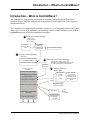
The ControlWave programming environment uses industry-standard tools and protocols to
provide a flexible, adaptable approach for various process control applications in the industrial
automation business.
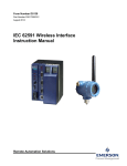
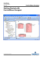
The ControlWave Programming Environment consists of a set of integrated software tools which
allow a user to create, test, implement, and download complex control strategies for use with the
ControlWave series of Process Automation Controllers.
1 Build your Control Strategy
Create a new
control strategy
from scratch
ACCOL 3
Function Block
Library
ControlWave
Designer
Development
Environment
I/O Configuration Wizard
2 Test your Control Strategy
I/O Simulator
IEC 61131 Real Time System
3 Download your Control Strategy
Load executable
ControlWave system Firmware
OpenBSI
Downloader
Process Automation
Controller
OpenBSI Downloader can perform
downloads. ControlWave Designer can also
be used to download and test hardware.
4
IEC 61131 Real Time System
Retrieve Data via
Web Pages
Data Access
ActiveX
Controls
Bristol Firmware
ControlWave
System Firmware
Load executable
HTML
Configuration Parameters
Other software
in which the
ActiveX controls
have been placed
e.g. Visual Basic,
Excel
Web pages running
in Internet Explorer
Real Time and Historical Data
ObjectServer
Project Source - compressed
(OPTIONAL)
Third
Party
software
OpenBSI Utilities
e.g. DataView
Harvester
PROCESS I/O BOARDS
Data From Field Input Devices
1
Getting Started with ControlWave
Introduction – What is ControlWave?
The tools which make up the environment are:
ControlWave Designer load building package offers several different methods for
generating and debugging control strategy programs including function blocks, ladder logic,
structured languages, etc. The resulting process control strategy programs (projects) are fully
compatible with IEC 61131 standards. Various communication methods are offered,
including TCP/IP, serial links, as well as communication to OpenBSI software and
networks. ControlWave Designer incorporates the KW MULTIPROG wt IEC 61131
programming tool. 1
The I/O Configuration Wizard, accessible via a menu item in ControlWave Designer,
allows you to define process I/O boards in the ControlWave-series controller, and configure
the individual mapping of I/O points for digital and analog inputs and outputs.
The ACCOL3 Function Block Library which is imported into ControlWave Designer,
includes a series of ControlWave-specific function blocks. These pre-programmed function
blocks accomplish various tasks common to most user applications including alarming,
historical data storage, as well as process control algorithms such as PID control.
The I/O Simulator allows the control strategy programs (projects) generated through
ControlWave Designer to be tested on a PC, with simulated analog and digital inputs and
outputs. The I/O Simulator utilizes the identical IEC 61131 real time system used in the
ControlWave controller; this allows initial I/O testing and debugging to be performed in a
safe, isolated environment, without the need for a running ControlWave-series controller and
process I/O boards.
The ObjectServer – a package you purchase separately that allows real-time data access by
any OPC compliant third-party software package.
A series of Web Page Controls are also available for retrieval of real-time data values,
historical data values, and communication statistics. The web controls utilize ActiveX
technology and are called through a set of fixed Web pages, compatible with Microsoft®
Internet Explorer. Alternatively, developers can place the controls in third-party ActiveX
compatible applications such as Visual BASIC or Microsoft® Excel, or in their own userdefined web pages to provide a customized human-machine interface (HMI).
1
KW MULTIPROG wt is an industry-standard tool developed by Kl_pper und Weige Software GmbH. KW
MULTIPROG wt is used by various PLC and RTU vendors for generating IEC 61131 code.
Getting Started with ControlWave
2
Starting ControlWave Designer, Opening A Project
Installing the Software
ControlWave Designer software is included on the OpenBSI CD-ROM.
To install it, choose “Install OpenBSI” from the choices provided in the CD browser, and then
select “ControlWave Designer with ACCOL III”. For more information on the installation
process, see Chapter 2 of the OpenBSI Utilities Manual (document# D5081).
Starting ControlWave Designer
ControlWave Designer is your IEC 61131 program development tool. It allows you to create a
control strategy (project) in any of five standard IEC 61131 languages, compile the program,
debug it, and download it into your ControlWave controller.
To start ControlWave Designer click on:
StartProgramsOpenBSI Tools ControlWave Tools ControlWave Designer
IMPORTANT: If this is the very first time ControlWave Designer has been started on this
particular computer, you will be reminded to register the software. Otherwise, the software
can only be used for a maximum of 60 days. For more information on the registration
process, see Chapter 2 of the OpenBSI Utilities Manual (document# D5081).
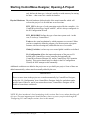
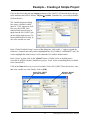
Opening A New Project
ControlWave Designer will start. Then, click on the
New Project icon, shown above, or click on
FileNew Project.
3
Getting Started with ControlWave
Starting ControlWave Designer, Opening A Project
The New Project dialog box will appear.
Double-click on the ‘ControlWave’ icon (or the ‘CWMicro’ icon if you are using a ControlWave
Micro-series unit) and a project tree will be created which automatically includes the ACCOL3
function block library.
We will briefly discuss some of the terminology associated with the project tree. The project tree
includes a series of folders and worksheets which define the various elements of your project.
Among the most important elements of the project tree are:
Getting Started with ControlWave Designer
4
Starting ControlWave Designer, Opening A Project
Logical POUs
Program Organization Units (POUs) hold the program code for your
project. They are defined on three separate worksheets. One worksheet
can optionally contain a textual description of the POU, a second
worksheet lists the variables associated with the POU, and a third
worksheet defines the POU code. POUs can be up to 640 K bytes in size,
and there is an enforced limit of 512 POUs per project. There are three
types of POUs:
Functions - Sometimes the term function is abbreviated as ‘FU’. These
are the simplest type of POU. They can take multiple inputs, but they
generate only one output. The memory allocated for a function’s data is
not persistent; i.e. once the function completes execution, that memory is
released. Functions are generally used to perform mathematical
operations; an example of a function is R_INT which truncates a real
number to an integer. Functions can only call other functions. Functions
can only be executed when included as part of a program POU.
Function Blocks - Sometimes the term function block is abbreviated as
‘FB’. Function blocks can take multiple inputs, and they can generate
multiple outputs. Unlike functions, they can have persistent memory. Most
of the POUs provided in the ACCOL3 library are function blocks, for
example, the AVERAGER, the INTEGRATOR, the PID3TERM, the
LEADLAG, etc. User-defined function blocks can be created which
consist of logical connections of various functions and function blocks.
Function blocks can only be executed when included as part of a program
POU.
Programs – Programs are essentially groups of functions and function
blocks which have been logically connected together to perform some
task. Programs are the only type of POU which can actually be executed.
Users can create more than one program in a project, and in fact, they can
create multiple instances of the same program. Programs can contain
persistent memory.
Libraries
There are two types of libraries: Firmware libraries are libraries of
functions and function blocks created specifically for this controller
model. The ACCOL3 library is a firmware library containing functions
and function blocks created specifically for the ControlWave-series of
controllers. It is automatically loaded when you choose the ControlWave
Template in the New Project dialog box. User libraries are optionally
created by the user. They are libraries of programs, functions, and function
blocks called in from other previously saved projects.
Data Types
The Data Type worksheets can be used to define customized data type
structures. For example, arrays of numbers. NOTE: The data entered here
5
Getting Started with ControlWave
Starting ControlWave Designer, Opening A Project
only defines the data type, it doesn’t actually set aside memory for storing
the data - - that occurs in a variable declaration.
Physical Hardware Physical hardware defines details of the actual controller which will
execute the project. It is divided into several sections:
RTU_CFG is the type of code generation required for the controller – for
ControlWave this always begins with IPC, and it is always configured via
the IO Configuration Wizard.
RTU_RESOURCE defines the type of run-time system used – in this
case, it is always 'ControlWave'.
Tasks are the actual mechanism by which programs are executed. When
you have completely defined a program, you must associate a program
instance with an executing task, and define the rate of execution.
Global_Variables is where any user-created global variables are defined.
IO_Configuration defines the inputs and outputs of the process I/O
boards in the ControlWave-series controller and optionally the
ControlWave Remote Ethernet I/O, and/or ControlWave I/O Expansion
Rack(s). This section should only be edited via the IO Configuration
Wizard; do NOT attempt to edit it manually.
Additional worksheets are added to the project tree as you build your project. Some of these are
added automatically, others must be manually added by the user.
IMPORTANT
Do not rename items in the project tree created automatically by ControlWave Designer,
such as the ‘IO_Configuration’ item. ControlWave Designer looks for worksheets under
specific items of the tree, and if you rename those items, ControlWave Designer will be
unable to locate those worksheets.
NOTE: We have introduced a lot of terminology in this section. Don’t worry about absorbing all
of it now. The most important parts should become clearer to you as you proceed through the
‘Configuring I/O’ and Example sections, later in this manual.
Getting Started with ControlWave Designer
6
Configuring I/O
Configuring I/O
In order to reference I/O points on the process I/O boards of your controller, you need to
configure them within your project.
Although it is possible to manually edit the “IO_Configuration” section of the project tree, we
strongly recommend you use the I/O Configuration Wizard, as it will perform syntax checking,
and is easier for most users.
The I/O Configuration Wizard is accessible from within ControlWave Designer by clicking as
follows: ViewIO Configurator
When started, any existing I/O configuration data will be read and displayed in the I/O
Configuration Wizard. The Configuration Wizard is a multi-page tool; [>>Next>>] and
[<<Back<<] buttons are provided to allow you to move between the pages. A [Settings] push
button allows the user to rename default variable names, if necessary. (See ‘Changing Default
Variable Names’, later in this section.) NOTE: Page 1 allows the user to define multiple
resources. Typically, only a single resource is used, so by default, page 2 will appear first since
most users do not need to use Page 1.
IMPORTANT
The IO Configuration Wizard will add a variable group to the Global_Variables worksheet
called IO_GLOBAL_VARIABLES. Both the IO_GLOBAL_VARIABLES group in the
Global_Variables worksheet and the IO_Configuration worksheet should never be manually
edited by the user; these should only be modified through the IO Configuration Wizard.
7
Getting Started with ControlWave Designer
Configuring I/O
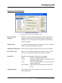
I/O Configuration Wizard (Step 1 of 3): (Most users can skip to Step 2)
The first page of the I/O Configuration Wizard allows the user to select from the available I/O
configurations and I/O resources. NOTE: Because most projects utilize a single configuration
and resource, this page is skipped when first starting the I/O Configuration Wizard. It is
accessible, however, by clicking on the [<<Back<<] button from the second page of the Wizard.
Available
Configurations
This lists all configurations in the current project. Select the I/O
Configuration Section for which you are defining the I/O.
NOTE: Typically, projects utilize a single I/O configuration
section.
Available Resources
This lists all resources for the selected I/O configuration. Choose
the resource for which I/O is to be defined. NOTE: Typically,
projects utilize a single resource.
Click on [Next>] to proceed to the next step.
Getting Started with ControlWave Designer
8
Configuring I/O
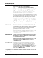
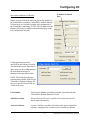
I/O Configuration Wizard (Step 2 of 3):
The second page of the I/O Configuration Wizard allows the user to specify which process I/O
boards are actually installed in the ControlWave-series controller, as well as boards which are
installed in separate devices such as I/O Expansion Racks, or Remote Ethernet I/O units.
Boards should be selected from the selection boxes in the ascending order of their slot number.
First, use the “Unit Type” list box to identify which type of ControlWave controller you are
configuring, then select the desired boards, and click on [ADD].
If this controller has associated I/O racks, or Remote Ethernet I/O units, choose those boards in
the “Ext Rack Board” and “Remote IO Boards” selection boxes and click on [ADD].
For more information on the various fields, see below:
Unit Type
This field allows you to identify the type of ControlWave-series
controller you are configuring, so that the proper board types can be
9
Getting Started with ControlWave Designer
Configuring I/O
displayed for it. The types of controllers include:
CW_
ControlWave Process Automation Controller
CWM_
ControlWave MICRO Process Automation Controller
LP_
ControlWave Low Power (LP) Process Controller
CXX_
ControlWave CW_30 or CW_10 Controller
Once you select the type of controller, the boards which can be
installed in that unit will be displayed as possible choices.
For ease of configuration, select the boards from the list in ascending
order of their slot number in the ControlWave unit. Clicking once on
the board abbreviation will cause a description of the board to be
displayed at the bottom of the Wizard page. Double-clicking on the
board abbreviation (or clicking once on the board and then clicking
on [ADD]) will add the board to the “Selected Boards List”. The
‘I/O Configurator’ section of the ControlWave Designer
Programmer’s Handbook (document# D5125) lists the various types
of boards.
Ext Rack Boards
This lists boards which may be installed in the ControlWave I/O
Expansion Rack. If this ControlWave-series controller is configured
to use an I/O Expansion rack, select the appropriate boards in
ascending order of their slot number in the rack.
Double-clicking on the board abbreviation (or clicking once on the
board and then clicking on [ADD]) will add the board to the
“Selected Boards List”
Remote IO Boards
This lists boards used in ControlWave Remote Ethenet I/O units. If
this ControlWave controller is configured to use Remote Ethernet
I/O, select the appropriate boards.
Double-clicking on the board abbreviation (or clicking once on the
board and then clicking on [ADD]) will add the board to the
“Selected Boards List”
Selected Boards List
This list allows the user to declare which boards reside in the
ControlWave controller or its configured ControlWave Remote
Ethernet I/O unit(s), or ControlWave I/O Expansion Racks. To
remove a board from the “Selected Boards List” double-click on it,
or click on it once, and then click on [REMOVE]. To remove all
boards click on [REMOVE ALL].
Click on [Next] to verify configuration information, adjust slot numbering, define zeros and
spans for analog inputs, etc.
Getting Started with ControlWave Designer
10
Configuring I/O
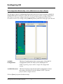
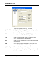
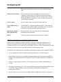
I/O Configuration Wizard (Step 3 of 3):
The third page of the I/O Configuration Wizard displays configuration details for each board. To
see the details, click on the board abbreviation, and the configuration details will be displayed on
the right hand side of the page. NOTE: The fields available for particular boards vary from
platform to platform.
Selected Boards List
Displays all boards selected on the previous page. Click on a particular
board abbreviation to display configuration details for the board.
Board Name
A name for the board can be specified here. This name will be used
when configuring pins for the board.
Map Type
(Information Only) Depending upon the type of board, separate
memory areas (called maps) are reserved for either inputs or outputs.
Some boards have both an input map and an output map. For example,
a digital output board has outputs (DOs) in its output map, but it may
also have inputs which indicate board status conditions and errors. For
more detailed information on the input and output maps for various
boards, see the ‘I/O Mapping’ section of the ControlWave Designer
Programmer’s Handbook (document# D5125).
NOTE: If you have an older ControlWave project in which you changed
the map type from the default choice, this may cause errors to be
11
Getting Started with ControlWave Designer
Configuring I/O
generated when the project is rebuilt. If this occurs, you should delete
the board definition and re-define the board.
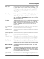
Start… End Address
Displays the range of memory addresses used by the board.
Slot Number
Displays either the physical I/O slot in the ControlWave controller
which holds the board, or if this is a Mixed I/O Board (MIOB) it
displays a board selection number. For ControlWave and ControlWave
Micro, I/O slot numbers are positive integers, e.g. 1, 2, 3, etc. For the
ControlWaveLP, the slot number is 0 for all boards except for the AO;
for the AO the slot can be 8 to 13. NOTE: I/O Slot number is NOT the
same as the chassis slot number. Chassis slots which hold the power
supply and CPU boards are not considered to be I/O slots, so the first
I/O slot is typically the third chassis slot.
IP Address
ControlWave Remote Ethernet I/O boards are identified by their
Internet Protocol (IP) address, instead of the I/O slot number. The same
is true for boards residing in a ControlWave I/O Expansion Rack.
Related Task
Shows the name of the task which uses this board. In some cases, for
example, when using Ethernet I/O, or analog boards in an RTU 3340, it
is important to associate a board with the task which uses the board.
When a board is associated with a task, that board will be read / written
to, at the rate cycle associated with the task, thereby ensuring up-to-date
information for calculations performed in the task. When no task is
associated with the board, board execution is associated with the default
task, which runs at a lower priority, and therefore may not provide
sufficient up-to-date I/O information when it is required by a task.
Mark Variables as
PDD OPC
This determines how values of the I/O variables associated with this
board will be made available to other software programs. Checking
“PDD” allows the controller to reference variables by name, which is
necessary if you intend to access a variable by external software which
requires ‘read-by-name’ access, such as DataView, or one of the other
OpenBSI Utilities. Checking “OPC” adds this variable to a collection
list used by the ObjectServer or by the OpenBSI Signal Extractor. This
is necessary when data is to be extracted, and sent to a database.
When edits have been made to this page, click on the [Show xxx Information] button. The
name on this button, and the pin configuration details, vary depending on the type of board being
configured. See the pages that follow for the standard board types.
NOTE: If you are using RIO Open Modbus board types, please see the ‘I/O Configurator’
section of the ControlWave Designer Programmer’s Handbook (document# D5125).
Getting Started with ControlWave Designer
12
Configuring I/O
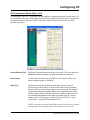
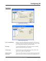
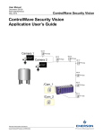
Analog Boards
\
Analog Input Board Page (CWM_AI8 board)
(some of these fields do NOT appear for other models)
Analog Output Board Page (CW_AO8 board)
(some of these fields do NOT appear for certain models)
13
Getting Started with ControlWave Designer
Configuring I/O
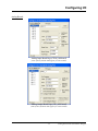
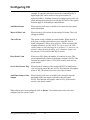
Low Level Analog Input Board (CXX_LL4 Board)
List of Available
Pins
Displays a list of the individual pins (I/O points) on this process I/O
board. If the pin is displayed in RED, that pin is active. If the pin is left
grayed out, that pin is considered unused.
Pin Name
Defines a name identifying this pin. IMPORTANT: This name is used
as a variable name to reference the I/O pin in your POU.
Value
Defines the initial value for this I/O pin, in floating point format.
NOTE: This is not available for analog input pins.
Zero
Defines the lowest value of the range for this I/O pin. Used to scale the
input/output value.
Span
Span is added to the ZERO value to define the highest value of the
range for this I/O pin. Used to scale the input/output value.
Add Over Range
Status
When selected, will cause a variable to be created to store the value of
the overrange status bit. Over range conditions occur when an attempt
is made to drive the variable associated with this pin outside the range
defined by the zero and span. When this occurs, the over range status
bit will be set to TRUE.
Getting Started with ControlWave Designer
14
Configuring I/O
Range Type
For some boards, you can specify whether the board input is in current
or voltage. Choose ‘VOLTS’ or ‘AMPS’. NOTE: For example, if 4 to
20 milliamps of current drive the board, you would choose ‘AMPS’,
then enter 0.004 for the “Bottom Range” value, and 0.020 for the
“Top Range” value.
Bottom Range
The lowest usable value for VOLTS or AMPS for this board input. For
example, if the board input can range from 1 to 5 VOLTS, the
“Bottom Range” would be set to 1.0. If this board input can range
from 4 to 20 milliamps, “Bottom Range” would be set to 0.004. Other
ranges are possible as well.
Top Range
The highest usable value for VOLTS or AMPS for this board input. For
example, if the board input can range from 1 to 5 VOLTS, the “Top
Range” would be set to 5.0. If this board input can range from 4 to 20
milliamps, “Top Range” would be set to 0.020. Other ranges are
possible as well.
Set Actual Output
Value
When selected, this will cause a variable to be created which displays
the actual value which was written to the output pin.
Add Board Status
When selected, will cause a variable to be created to store board status
information.
Add Last Operation
Status
When selected, will cause a variable to be created to store the status of
the last conversion operation information.
Calibration Error
This is only present for certain platforms. When checked, will cause a
variable to be created to store error information. This variable will be
set to TRUE whenever there is bad calibration data in the EEPROM.
Board Time Out
This is only present for certain platforms. When checked, will cause a
variable to be created to store information about board time out errors.
Board time outs occur if there is a problem with conversion operations.
Mark All Pins Used
When checked, will activate all pins on this I/O board. They will all
appear in RED.
Configure Hold
Values
When checked, enables other fields on the page for configuring a hold
value for this pin. A hold value is the value used by the I/O card if it
detects a watchdog of the ControlWave CPU. The I/O board maintains
this value at the pin until the unit is restarted.
Update Default
When checked, allows the "User Configured Output" hold value to
15
Getting Started with ControlWave Designer
Configuring I/O
Value
be changed on-line; otherwise the hold value can only be set in the I/O
Configurator.
Hold Last Output
When checked, specifies that during a watchdog failure, the hold value
for this pin will be whatever value was on the pin when the failure
occurred. NOTE: "Hold Last Output" and "User Configured
Output" are mutually exclusive. Either one may be configured for a
particular pin, but NOT both.
User Configured
Output
When checked, allows the user to enter a value for this pin which will
be used as the hold value in the event there is a watchdog failure of the
ControlWave. NOTE: "Hold Last Output" and "User Configured
Output" are mutually exclusive. Either one may be configured for a
particular pin, but NOT both.
Point Type
(Not Shown) Appears for CXX_LL4 Low Level Analog Input Board
only. Specifies the type of low-level analog input. See the table, below,
for a list of supported temperature/voltage ranges for inputs to the
CXX_LL4 board.
Point Type
Thermocouple Type B
Thermocouple Type E
Thermocouple Type J
Thermocouple Type K
Thermocouple Type R
Thermocouple Type S
Thermocouple Type T
Resistance Temperature Device (RTD)
Voltage
Range
100 C to 1820o C
-270o C to 1000o C
-210o C to 1200o C
-270o C to 1370o C
-50o C to 1720o C
-50o C to 1760o C
-270o C to 400o C
-220o C to 850o C
-10 mV to 10 mV
o
When all pins have been configured, click on [Done]. You can then proceed to select and
configure pins for another board.
Getting Started with ControlWave Designer
16
Configuring I/O
Digital Boards
Digital Input Board Page
(Not all fields are present for all board types)
Digital Output Board Page
List of Available Pins
Displays a list of the individual pins (I/O points) on this process
I/O board. If the pin is displayed in RED, that pin is active. If the
pin is left grayed out, that pin is considered unused.
Pin Name
Is a name identifying this pin. This name is used as a variable
name to reference the I/O pin in your POU.
Set Pin Status
Sets the initial value for this digital output (DO). NOTE: This
option is not available for digital inputs.
Enable Counter
Processing
Turns on or off the counters associated with the digital input (DI)
process I/O board. Counters are used in certain applications. For
17
Getting Started with ControlWave Designer
Configuring I/O
example, if a mixed I/O board is used with a ControlWaveLP, a
digital input (DI) can be used as a low speed counter (30
millisecond filter). Enabling counter processing in such a case will
allow interrupt processing to occur for that DI. NOTE: This option
does not apply to all board types and platforms.
Add Board Status
When selected, will cause a variable to be created to store board
status information.
Mark All Pins Used
When checked, will activate all pins on this I/O board. They will
all appear in RED.
Turn off Leds
This option is only available on certain boards. When checked, it
will create a variable which allows you to turn OFF the I/O
board’s diagnostic LEDs to save on power. LEDs are turned OFF
when the variable is set ON. NOTE: For this to work, the LED
enable jumper on the board must be in position 2-3; otherwise, the
software cannot disable the LEDs, only a hardware jumper can.
See manual CI-ControlWaveMICRO for details.
Reset Point Count
When set to ON, allows the number of counts to be reset. This
occurs automatically whenever the board is restarted. NOTE: This
function only applies when a CXX_DI16 board is used as a low
speed counter.
Set No Init Counter Flag
When checked, counters on the board will NOT be initialized to
zero on a warm start of the unit. NOTE: This function only applies
when a CXX_DI16 board is used as a low speed counter.
Add Time Stamp of Last
Sample
When selected, will cause a variable to be created to store the
timestamp of the last sample collected by this I/O board.
NOTE: This function only applies when a CXX_DI16 board is
used as a low speed counter.
When all pins have been configured, click on [Done]. You can then proceed to select and
configure pins for another board.
Getting Started with ControlWave Designer
18
Configuring I/O
High Speed Counter (HSC) Boards
High Speed Counter Page
(Not all fields are present for all board types)
List of Available
Channels
Displays a list of the individual channels (counter I/O points) on
this process I/O board. If the channel is displayed in RED, that
channel is active. If the channel is left grayed out, that channel is
considered unused.
Channel Name
Is a name identifying this channel. This name is used as a variable
name to reference the channel in your POU.
Add Input Channel State When selected, displays the TRUE/FALSE value of the channel.
Reset Point Count
When set to ON, allows the number of counts to be reset. NOTE:
This occurs automatically whenever the board is restarted.
Select Filter
Specifies how the board will operate for this channel:
'None'
Defaults to 30 millisecond filtering.
'30 ms'
Turns on 30 millisecond filter. Typically used for
push-button debouncing.
'1 ms'
Turns on 1 millisecond filter. Used for low speed
counter applications.
'HSC Channel' High Speed Counter (Default for CWM_RTU
board)
Add Board Status
When selected, will cause a variable to be created to store board
status information.
19
Getting Started with ControlWave Designer
Configuring I/O
Add Time Stamp of Last
Sample
When selected, will cause a variable to be created to store the
timestamp of the last sample collected by this I/O board.
Mark All Pins Used
When checked, will activate all channels on this I/O board. They
will all appear in RED.
Set No Init Counter Flag
When checked, counters on the board will NOT be initialized to
zero on a warm start of the unit. Requires 04.41 or newer
firmware.
Turn off Leds
(Not Shown) This option is only available on certain boards.
When checked, it will create a variable which allows you to turn
OFF the I/O board’s diagnostic LEDs to save on power. LEDs are
turned OFF when the variable is set ON. NOTE: For this to work,
the LED enable jumper on the board must be in position 2-3;
otherwise, the software cannot disable the LEDs, only a hardware
jumper can. See manual CI-ControlWaveMICRO for details.
Remote I/O Status Board
The Remote I/O Status Board is a 'virtual' board,
i.e. there is no actual physical board. By including
it within your ControlWave project, global
variables will be created to store communication
statistics information, and board ID strings for the
ControlWave I/O Expansion Rack.
For more information about these variables, and the software configuration for the ControlWave
I/O Expansion Rack, please see the ControlWave I/O Expansion Rack Quick Setup Guide
(document# D5122).
Getting Started with ControlWave Designer
20
Configuring I/O
IP address is defined
here.
Notes About Ethernet I/O Boards
Unlike process I/O boards which are physically installed in
the ControlWave controller, ControlWave Remote Ethernet
I/O boards are in a separate location, and communicate to
the ControlWave unit using TCP/IP. (The IP address for the
Ethernet I/O board is configured from the third page of the
I/O Configuration Wizard.)
Certain parameters must be
specified for the Ethernet I/O units
which hold the boards. Once this is
done, however, the configuration of
the individual board pins is
identical to that described earlier.
NOTE: The dialog box shown at
right includes possible fields for the
ControlWave Remote Ethernet I/O,
however, not all of these fields are
visible in all cases.
Unit Number
Specifies the Modbus unit address number associated with this
ControlWave Remote Ethernet I/O unit.
Add Driver Status
When selected, will cause a variable to be created to store I/O
driver status information.
Activate Counters
Creates / disables a variable which allows the user to control the
starting / stopping of the counters in the ControlWave Remote
21
Getting Started with ControlWave Designer
Configuring I/O
Ethernet I/O board. These counters are used with digital inputs
(DI).
Add Freshness Counter
When selected, will cause a variable to be created to store a
‘freshness’ counter value. The freshness counter represents the
number of program executions since new data has been collected
through this Ethernet I/O board. A value of 0, indicates the data is
as new (fresh) as possible.
Clear Counters
Sets all counter values associated with this board to 0.
Convert RTD value to
tenths
(For RIO 4RTD - 4 Digital Input Board ONLY) - When checked,
causes values from the Resistance Temperature Device board to be
divided by 10, thereby providing greater precision.
[Show Pins], [Analog
Pins], [Digital Pins]
When clicked on, calls up a dialog box for configuring the
individual pins for the board.
[Done]
Click here when configuration for this board is complete.
Additional Configuration For ControlWave Remote Ethernet I/O
Besides the I/O configuration within ControlWave Designer, additional configuration for
Ethernet I/O hardware must be performed using the Remote I/O Toolkit software (not to be
confused with what used to be known as the OpenBSI Technician Toolkit). Documentation on the
Remote I/O Toolkit software is provided in the form of on-line help screens.
The Remote I/O Toolkit software is included as an installation option on the OpenBSI CD ROM.
To use counters (DI) you must enable counters in the Remote I/O Toolkit software.
The IP address entered for a ControlWave Remote Ethernet I/O board in the ControlWave
Designer I/O Configuration Wizard must MATCH the IP address entered in the Remote I/O
Toolkit.
If you are using high speed counters, 32 bit counters must be enabled within Remote I/O
Toolkit.
For analog inputs/outputs (AI, AO) you must NOT change the default scaling within Remote
I/O Toolkit. Changes should only be made within the ControlWave Designer I/O
Configuration Wizard.
Be aware that if you are using counters (Digital Input or High Speed Counter), restarting of
Getting Started with ControlWave Designer
22
Configuring I/O
the ControlWave Remote Ethernet I/O will cause a large jump in counts.
If you intend to use TPO (Time Proportioned Outputs) for any point, you must enable TPO
for those points.
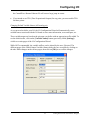
Changing Default Variable Names (All board types)
As you proceed to define your I/O, the I/O Configuration Wizard will automatically create
variable names associated with the I/O board to store status information, zeros and spans, etc.
These variable names are based on the pin name you define with an appropriate suffix added. To
see the default suffix, click on the [Variable Names] button (previously called [Settings])
visible on certain pages of the I/O Configuration Wizard.
While NOT recommended, the variable suffixes can be altered by the user, if desired. The
different pages of the Global Output Variables Names dialog box are accessible by clicking on
the tabs. Make changes on the various pages, then click on [OK] to save all the changes.
23
Getting Started with ControlWave Designer
Example – Creating A Simple Project
Example 1 – Creating A Simple Project
NOTE: This example shows one possible way to approach a problem. There are many different
solutions available.
The fictitious Sunken Valley Water Company wants to set up a PID (proportional, integral,
derivative) loop for controlling the flow of liquid through a pipeline.
They have a flow control valve to vary the flow,
and a flowmeter to measure it.
Both the valve and flowmeter are connected to a
ControlWave controller.
Before trying to create a project which will perform the PID control, we need to make a list of
each thing the project will be doing.
Bring in the flow data from the pipeline.
The flow in the pipeline is measured by the flowmeter FT101. The flow rate ranges from
0 to 500 gallons per minute. This data will come in through an analog input process I/O
board.
Slow down reaction to flow changes so as to reduce the amount of wear and tear on the
valve.
We want to ensure that we don’t wear out the control valve trying to respond too quickly
to changes in flow. To do this, we need to delay response to the input flow data using a
LEAD_LAG function block.
Perform the actual PID calculation.
To perform the actual PID control, we can use the pre-defined PID3TERM function
block.
Send data to the control valve.
The controller will have to send data out to the flow control valve (FIC101/FCV101), in
order to vary the position of the valve to regulate the flow. This will require an analog
output process I/O board.
Now that we know, roughly, what we’re trying to do, let’s create our project.
Getting Started with ControlWave Designer
24
Example – Creating A Simple Project
Step 1. Start ControlWave Designer:
Click as follows:
StartProgramsOpenBSI Tools ControlWave Tools ControlWave Designer
Step 2. Open A New Project:
Click as follows: FileNew Project
Choose the ‘ControlWave’ template (or ‘CWMicro’ if you have a ControlWave MICRO) in the
new project dialog box, and click on [OK].
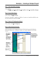
Step 3. Start the I/O Configuration Wizard:
Click as follows: ViewIO Configurator
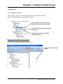
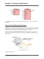
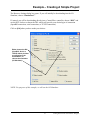
Step 4. Define Process I/O boards.
NOTE: By default, the I/O Configuration Wizard will skip the first page of the dialog box
because most applications, including this example, use a single configuration and a single
resource.
First, choose
the type of
ControlWaveseries
controller you
are configuring
in the “Unit
Type” list box.
Next, select the
board you want to
use from the list of
boards for that
controller type.
Then, click
on “Add” to
add the board
to the
“Selected
Boards List.”
Finally, click on
“Next.”
25
Getting Started with ControlWave Designer
Example – Creating A Simple Project
Our particular project will require two different process I/O boards. An analog input board is
needed to handle the analog input which provides the flow data. An analog output board is also
needed to send control data out to the valve. We will describe in detail how to define the analog
input board; once it is done, the analog output board should be defined by the same basic
approach.
First, choose the type of ControlWave controller you are using in the “Unit Type” field (‘CW_’
= ControlWave, ‘LP_’ =ControlWaveLP, ‘CWM_’ =ControlWave MICRO, ‘CXX_’= CW10 or
CW30. Choose the analog input board used in your unit, then click on [ADD]. Then click on
[Next>>].
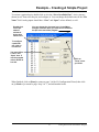
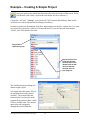
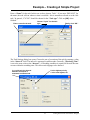
On the third page, click on the board in the “Selected Boards List” and its parameters will be
displayed on the right hand side of the dialog box. Enter the proper slot number for the board in
the “Slot Number” field. Then click on [Show Analog Pins Information] to configure the
individual I/O pins.
Enter the I/O
slot number
in the
controller
which holds
this board.
Click on the
board name
to display its
parameters.
Click here to
configure the
I/O pins.
Getting Started with ControlWave Designer
26
Example – Creating A Simple Project
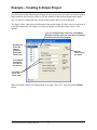
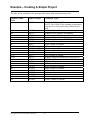
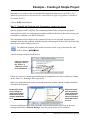
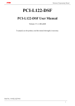
To activate a particular pin, double-click on it in the “List of Available Pins”. Active pins are
shown in red. Then select the pin, and configure it. You can change the default name in the “Pin
Name” field. Analog inputs should have “Zero” and “Span” values defined, as well.
Double-click
on the pin
name to
activate it.
Active pins
show in red.
You can change the pin name here; ControlWave
Designer uses the name you enter here to reference
the pin in the rest of the program.
To configure
a particular
pin, click on
it in the list.
You must define
a “Zero” and
“Span” here. If
not, the program
uses a default of
0 to 100.
Click on
“Done” when
you finish.
When finished, click on [Done] to return to page 3 of the I/O Configuration Wizard, then click
on [<<Back<<] to return to page ‘Step 2 of 3’, and add another board.
27
Getting Started with ControlWave Designer
Example – Creating A Simple Project
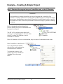
Now define an Analog Output board. Repeat the same general process used to create the Analog
Input board. Be sure you use a different I/O slot number for the Analog Output board, and be
sure you specify a unique pin name for the analog output, and set its zero and span.
The figure, below, shows the pin definition for the analog output. We have set a zero and span of
0 and 100 respectively; this range covers the percentage at which the control valve is to be
opened.
You can change the pin name here; ControlWave
Designer uses the name you enter here to reference
the pin in the rest of the program.
Double-click
on the pin
name to
activate it.
Active pins
show in red.
Click on
“Done” when
you finish.
To configure
a particular
pin, click on
it in the list.
You define a
“Zero” and
“Span” here.
When you finish with the I/O configuration, go to page ‘Step 3 of 3’ and click on the [Finish]
button.
Getting Started with ControlWave Designer
28
Example – Creating A Simple Project
Some notes about choosing variable names:
Variable names consist of a combination of letters (A-Z, a-z), numbers (0-9) and the
underscore character '_'.
The first character of a variable name CANNOT be a number.
Variables are NOT case sensitive, i.e. MY_VARIABLE, my_variable, and mY_vAriaBLe
are all considered to be the same variable name.
Although you won't always see it, in addition to the variable name you enter, the system
automatically precedes every variable by one or more instance names, separated by
periods, depending upon where the variable was defined ('@GV.' for global variables, task
and function block instance names for local variables) e.g. @GV.F101_INPUT or
Flow1.V003
If you have OpenBSI Utilities Version 4.0 or earlier, we recommend your variable names
be limited to 20 characters or less (including the instance name or '@GV.' described
above). This is recommended because prior to OpenBSI Version 4.1, tools such as
DataView only recognized the first 20 characters; and so, that is the only portion of the
variable name those tools will display. Newer versions recognize up to 64 characters.
If you decide to use longer variable names (up to 128 characters are allowed), only the
first 30 characters will be recognized within ControlWave Designer. If you have variables
in your ControlWave POU worksheet with more than 30 characters, however, make sure
there are no two variables in which the first 30 characters are the same, or else those two
variables will be treated as the same variable.
For example, two variables named: COMPRESSOR_STATION_FOUR_STATUS_ON
COMPRESSOR_STATION_FOUR_STATUS_OFF
and
should not be included in the same worksheet because the first 30 characters
'COMPRESSOR_STATION_FOUR_STATUS' are the same, and therefore the difference
between the '_ON' and '_OFF' would not be recognized by the compiler.
Here are some legal variable names:
COMPRESSOR_4_STATUS
_PUMP_START
tank_level_hi_alarm
Here are some ILLEGAL variable names, and the reason they are illegal:
1_STATION4_MAINSWITCH
PUMP#4_START
(*illegal because it starts with a number*)
(*illegal because the '#' character is NOT allowed*)
29
Getting Started with ControlWave Designer
Example – Creating A Simple Project
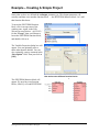
Step 5. Create A Program Which Implements Your Control Strategy
Now that we have our I/O configuration completed,
we can create a program which uses the I/O we have
defined.
To start, locate the “Logical POUs” object in the
Project Tree. Right-click on it and choose
“InsertProgram” from the pop-up menu.
(POU stands for Program Organizational Unit – it basically means a ‘program or sub-program’
in an IEC 61131 language. IEC-61131 supports five different programming languages; this
example uses FBD – Function Block Diagram language, however, you can choose any of the five
languages when you create your own programs.)
Creating A Program
The Insert dialog box opens.
Enter a name
for the
program.
Choose
“Program.”
For this example,
we choose “FBD.”
Choose
“<independent>.”
Choose
“<independent>.”
For this example, choose “Program” for the type and “FBD” for the Language.
Enter a name for the program we are defining. In this case we have decided on the name
‘Flow_Control_Program’.
The PLC type should be “<independent>” and the Processor Type should also be specified as
Getting Started with ControlWave Designer
30
Example – Creating A Simple Project
"<independent>".
Click on [OK] when finished.
A new ‘empty’ program will be added to the Project Tree. Double-click on the
‘Flow_Control_Program*’ icon to define the program.
This part allows you to enter a textual
description of the program (optional).
This part lists variables associated with
the program.
Double-click on this part to actually
define the program.
Inserting Function Blocks in the program
Now click in the right-most portion of the screen.
Click in this portion of the
screen
31
Getting Started with ControlWave Designer
Example – Creating A Simple Project
Now you must use the Edit Wizard located in the lower-left corner of the screen. (If the
Edit Wizard is not visible, click on the icon shown at left, to activate it.)
Choose the ‘ACCOL3’ “Group”, to access the ACCOL3 function block library, then use the
scroll bar to see which function blocks belong to the library.
In order to smooth out fluctuations of the flow input (and protect the flow control valve) we want
to feed our flow input into a LEAD_LAG function block. Locate the function block named
‘LEAD_LAG’ then double-click on it.
Choose the
<ACCOL3> group.
Use the scroll bar to
locate the desired
function block, then
double-click on that
name to add that
function block to
your program.
The Variable Properties dialog box,
shown at right, opens.
You might ask at this point, ‘Why is
the function block being called a
variable?’ The reason is that the
function block is referred to in the
program by an instance name, which
is like a variable name. The instance
name allows the program to
distinguish between different
Getting Started with ControlWave Designer
32
Example – Creating A Simple Project
instances of the same type of function block, for example, if you had two different LEAD_LAG
function blocks in the same POU. You can optionally enter a name of your choice for the
function block, or just use the default. You can also enter a comment in the “Description” field,
as we have done. Now click on the [OK] push button.
A graphical representation of the LEAD_LAG function block will be displayed on the screen.
Each parameter name for the function blocks in the ACCOL3 library begins with two or more
lowercase letters. These lowercase letters (which we will call the prefix) identify whether the
parameter is an input, an output, or both an input and output, followed by the possible data types
for the parameter.
The identifier for
this function block
is “LEAD_LAG1.”
The type of
variable
precedes the
parameter name.
The first letter is always an 'i' for INPUT, or an 'o' for OUTPUT. If a parameter can be both an
INPUT and an OUTPUT, the second letter is an 'o'. Otherwise, the second, and any other letters
in the prefix indicate the various data types allowed for this parameter. The possible types are:
ab
ais
ar
arb
aus
b
di
i
r
s, si
s, str
ud,udi
ui
us
a, any
BOOL variable required. NO constants allowed.
STRING or INT variable required, depending on the usage. No constants allowed.
REAL variable required. NO constants allowed.
REAL or BOOL variable required. NO constants allowed.
USINT variable or array of USINT required. No constants allowed.
BOOL variable or constant
DINT variable or constant
INT variable or constant
REAL variable or constant
SINT variable or constant
STRING (Note: Character strings must be surrounded by single quotes.)
UDINT variable or constant
UINT variable or constant
USINT variable or constant
if not followed by any other prefix letters, then any of the following variable
types: REAL, SINT, INT, DINT are valid, however, NO constants allowed
33
Getting Started with ControlWave Designer
Example – Creating A Simple Project
The table, below, summarizes the meaning of the letters in the parameter name prefix.
Parameter Name
Prefix
ia, iany
Input or Output
Valid Data Types:
INPUT
iab
iais
iar
iarb
iaus
ib
idi
ii
ioab
ioar
ir
is, isi
is, istr
iudi
iui
ius
ob
odi
oi
or
oud
oui
Ous
INPUT
INPUT
INPUT
INPUT
INPUT
INPUT
INPUT
INPUT
INPUT & OUTPUT
INPUT & OUTPUT
INPUT
INPUT
INPUT
INPUT
INPUT
INPUT
OUTPUT
OUTPUT
OUTPUT
OUTPUT
OUTPUT
OUTPUT
OUTPUT
REAL, SINT, INT, DINT
NOTE: You CANNOT use constants on parameters
with the 'ia' or 'iany' prefix; only variables may be
used.
BOOL variable - NO constants allowed.
STRING or INT variable. No constants.
REAL variable - NO constants allowed.
REAL or BOOL variable. NO constants allowed.
USINT variable or array of USINT. No constants.
BOOL variable or constant
DINT variable or constant
INT variable or constant
BOOL variable - NO constants allowed.
REAL variable - NO constants allowed.
REAL variable or constant
SINT variable or constant
STRING (must be surrounded by single quotes)
UDINT variable or constant
UINT variable or constant
USINT variable or constant
BOOL variable or constant
DINT variable or constant
INT variable or constant
REAL variable or constant
UDINT variable or constant
UINT variable or constant
USINT variable or constant
Getting Started with ControlWave Designer
34
Example – Creating A Simple Project
Click on the dot feeding into the irInput parameter of the LEAD_LAG function block, then go
to the menu bar and click as follows: ObjectsVariable (Alternatively, you could just doubleclick on the dot.)
The Variable Properties dialog
box opens. A default variable
name of ‘V001’ appears as well.
However, the LEAD_LAG
function block must receive its
input from the F101_INPUT pin
on the Analog Input process I/O
board (defined earlier in Step 4);
that is the variable we want.
In the ‘Global Variable Groups’ section of the dialog box, click on the ‘+’ signs to expand the
folder tree. Continue this until you have highlighted the ‘IO_GLOBAL_VARIABLES’ item. We
want to highlight this item because it will contain the I/O variable defined earlier.
In the ‘Scope’ section, click on the “Global” button. (‘Global’ refers to anything that is
accessible to all POUs in this ControlWave project; ‘Local’ refers to something that is confined
to the current POU.)
Click in the Name list box to see a list of variables. Select F101_INPUT from the list box, since
that is the variable we want. Finally, click on [OK].
Select F101_INPUT
from the list box.
35
Choose “Global”
for the scope.
Getting Started with ControlWave Designer
Example – Creating A Simple Project
The ‘F101_INPUT’ variable will now be displayed on the
irInput parameter of the LEAD_LAG function block.
Next, we can proceed to define variable names for the other inputs (irDerivative, irIntegral,
and ibReset).
Double-click on the IrDerivative parameter. A variable name will automatically be assigned, in
this case ‘V002’. You can enter a different name, or accept V002. Alternatively, you can just
enter a constant value here, instead of a variable name, if this parameter does not have an 'ia' or
'iany' prefix (see table on page 34) and you know that this value will never need to be changed,
and you don’t intend to collect/display it at the PC. (If you encounter the error ‘Operand not
implemented or area exceeded’ at download, this indicates that you should NOT have used a
constant because this parameter has an 'ia' or 'iany' prefix.)
This is a default name ControlWave Designer
assigns automatically. You can change it if
desired, or leave it as is.
You can reference a
“Global” variable outside
of this POU. Any I/O
variable must be “Global.”
If you want to define a
non-I/O variable as
“Global” we recommend
you do NOT mix I/O and
non-I/O in the same
variable worksheet.
You can only reference a
“Local” variable within this
POU. Typically, you should
choose “Local” unless this
is an I/O variable which
references data going
directly form/to an I/O
board, or it is being shared
among more than one
POU.
Enter an initial value here.
Choose the data type based on
the prefix letters for the parameter name:
r = REAL
b = BOOL
Getting Started with ControlWave Designer
36
Example – Creating A Simple Project
NOTE: You’ll notice that you have the option of defining the new variable as either ‘Local’ or
‘Global’ . (If the Local/Global options are “grayed out,” de-select the Show all variables of
worksheets button to access them.)
As we noted before, Local variables are only accessible within this POU. If you define a variable
as a local variable, and you create another POU, you will NOT be able to access the local
variables in the first POU; they are completely unknown to the second POU. If you define a
variable as global, it is accessible in the current POU, and in any other POUs you define for this
project. This distinction isn’t too important for this particular example, however, it is discussed
in detail in the ControlWave Designer Programmer’s Handbook (document# D5125).
We recommend, however, that if you are NOT defining an I/O variable for an I/O board that you
choose "Local". Alternatively, if you do choose "Global", make sure you choose the ‘Default’
variable group, or some other variable group you have defined. Do NOT choose the
‘IO_GLOBAL_VARIABLES’ group for any non-I/O variables.
Choose the proper “Data type”, in this case ‘REAL’, and enter an “Initial value”, if desired. (In
this case the initial value is the default value of 0.0, some of the other variables in this example
will require initial values).
Although we aren’t using them in this example the “RETAIN”, “PDD” and “OPC” fields are
useful. The “RETAIN” box is checked if you want the last value of this variable to be used on
re-start after a power failure or warm download.
Checking the “PDD” box allows the controller to reference this variable by name. Reference by
name is necessary if you intend to access this variable by external software which requires ‘readby-name’ access, such as DataView, or other OpenBSI Utilities.
Checking the “OPC” box adds this variable to a collection list used by the ObjectServer, or by
the OpenBSI Signal Extractor. This is necessary when data is to be extracted and sent to a
database.
Finally, click on [OK] when finished.
Repeat this process for the other input variables in the
LEAD_LAG function block - -irIntegral, and ibReset. The
irIntegral will be of the REAL data type and should be
assigned an initial value of 0.7. The ibReset will be of the
BOOL data type and should be assigned an initial value of
FALSE (i.e. OFF). When finished, the LEAD_LAG
function block should appear similar to the figure shown at
right.
37
Getting Started with ControlWave Designer
Example – Creating A Simple Project
Notice that we have not defined the orOutput parameter yet. This Output parameter will
actually send data out to another function block - - the PID3TERM function block. Let’s add
that function block now.
To insert the PID3TERM function
block, click in an open area of the
window pane. Again, in the Edit
Wizard you must choose ‘<ACCOL3>’
for the “Group”, then scroll down to
locate the PID3TERM function block,
and double-click on it.
The Variable Properties dialog box will
appear. You can optionally enter a
name other than the default. You can
also, optionally, enter a comment in the
“Description” field. Then just click on
[OK].
Now we have two different function blocks:
The PID3TERM function block will
appear. We now have two function
blocks, LEAD_LAG and PID3TERM.
Getting Started with ControlWave Designer
38
Example – Creating A Simple Project
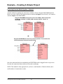
Connecting Function Blocks Together – Method 1
We want to feed the output of the LEAD_LAG function block (i.e. a smoothed out flow value)
into the input of the PID3TERM. There are various ways to do this; in this method, click on the
‘Connect Objects’ icon (shown above), then click on the green dot representing the orOutput
parameter of the LEAD_LAG function block. Move the mouse horizontally and you will notice
that a red line is drawn as you move the cursor.
Dot representing
the Output parameter
Dot representing
the Input parameter
Move the
cursor to
make a line
which
connects the
two dots
Position the cursor on the blue dot representing the irInput parameter of the PID3TERM
function block and click. The connection has now been made.
A connection has now been established.
39
Getting Started with ControlWave Designer
Example – Creating A Simple Project
Connecting Function Blocks Together – Method 2
Another method for making the connection would have been to drag the PID3TERM function
block over to the LEAD_LAG function block so that the orOutput of the LEAD_LAG connects
with the irInput of the PID3TERM.
Drag the PID3TERM function block over to the LEAD_LAG function block
so that the “orOutput” of LEAD_LAG connects with the “irInput” of
PID3TERM.
Drag the PID3TERM back over to its previous position. This stretches the
connection between the two function blocks.
Once the connection has been established, the PID3TERM can be dragged back to its previous
location; the connection between them will stretch accordingly.
NOTE: This method is only appropriate if you have a small number of function blocks, and a
small number of connections to make.
Getting Started with ControlWave Designer
40
Example – Creating A Simple Project
Now you can proceed to define the irSetpoint, irDeadband, irProportion, irIntegral,
irDerivative, irReset, ibTrack, and orError variables of the PID3TERM by double clicking on
each parameter (see previous examples of this process on pages 35 to 37). Don’t forget to choose
the correct data type (in this case ‘REAL’ or ‘BOOL’), and, for the input variables, assign
appropriate initial values for this example. The table, below, shows the correct data types and
some recommended initial values for this example:
PID3TERM Parameter
Name
IrSetpoint
IrDeadband
IrProportion
IrIntegral
IrDerivative
IrReset
IbTrack
OrError
Data Type
REAL
REAL
REAL
REAL
REAL
REAL
BOOL
REAL
Initial Value for this example
40.0
0.0
2.0
0.5
0.0
0.0
FALSE
Not applicable
Choose F101_OUTPUT which
is the name of PIN1 on the
analog output board.
That just leaves the orOutput parameter of the PID3TERM. Remember that we need to feed the
output of the PID controller out to the analog output process I/O board, so it can actuate the flow
control valve, thereby controlling the flow in the pipeline. We defined the output pin for this
purpose to be F101_OUTPUT; we can reference that now. Double-click on the orOutput and
choose F101_OUTPUT from the “Name” field in the Variable Properties dialog box.
(Remember that to do this, you have chosen the IO_GLOBAL_VARIABLES group from the tree,
and clicked on the “Global” button.
So now we have defined data types for all of our variables, entered initial values where
necessary, etc.
41
Getting Started with ControlWave Designer
Example – Creating A Simple Project
Our program (POU) is done! In order to make it do anything, however, it has to be associated
with a task.
Step 6. Create A Task Which Can Run The Program
Tasks determine how fast a program, or program(s) are executed. When a task is started, it reads
all inputs from the input process I/O boards, it then performs all calculations in the programs of a
task, and then it writes output data out through the output process I/O boards.
Tasks are found below the “Physical Hardware” branch of the Project Tree. To create a task,
right-click on the “Tasks” icon in the project tree, and choose “Insert” and “Task’ from the
pop-up menu.
Right-click on “Tasks” and
choose Insert Task.
The Insert dialog box opens.
Getting Started with ControlWave Designer
42
Example – Creating A Simple Project
Enter a “Name” for the task. In this case we have chosen ‘Task1’. If you enter ‘DEFAULT’ for
the name, the task will run whenever time is available - this is sometimes referred to as the ‘idle
task.’ In general, ‘CYCLIC’ should be chosen for the “Task type”. Click on [OK] when
finished.
Enter a name for the task.
Choose “Cyclic” for the task
type.
Finally, click “OK.”
The Task Settings dialog box opens. Choose the rate of execution of the task by entering a value
in the “Interval” field. The interval is measured in milliseconds. Generally, “Watchdog Time”
is set to the same value as the “Interval”. A Watchdog condition is reported if the task does not
execute within the watchdog time. This allows task slippage to be detected.
In a cyclic task, the interval
between executions is
measured in milliseconds.
0 is the highest priority,
1 is the next highest, etc.
43
Getting Started with ControlWave Designer
Example – Creating A Simple Project
If desired, specify a “Priority” for the task. ‘0’ is considered the highest priority. ‘1’ is the next
highest priority, and so on.
NOTE: If you chose ‘DEFAULT’ as the task name, the task will NOT execute according to an
interval, but instead, will be executed whenever time is available. It serves as the idle task.
When finished, click on [OK] and the task will have been defined.
Now that the task exists, however, it is necessary to associate the program that we wrote with the
task. Otherwise we will just have an empty task executing. To associate the program with the
task, right-click on the icon for the task in the project tree, and choose “Insert” and “Program
instance” from the pop-up menu.
The Insert dialog box opens. Choose “Program instance” as the “Type”.
First, choose “Program
Instance.”
Then, assign a
unique name here.
“Program type” should
be the type of program
you defined. In this case
“Flow_Control_Program.
”
Click “OK” when you
finish.
When we insert the program, we are actually creating something called a program instance.
Each program instance must be assigned a unique name - - in this case we chose ‘Flow1’. The
program instance is essentially a copy of the ‘Flow_Control_Program’ program we created.
Copies are used because, theoretically, you might want to use the same program in different
tasks, and if you didn’t use a copy there would not be available memory for internal (local)
variables for each separate copy.
All local variables created in a POU are only for a particular instance. This becomes very
Getting Started with ControlWave Designer
44
Example – Creating A Simple Project
important if you want to create a user defined function block from one of your POUs. (User
defined function blocks are discussed in the ControlWave Designer Programmer’s Handbook,
document# D5125.)
Click on [OK] when finished.
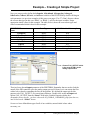
Step 7. Compile the Program and, if necessary, correct any errors
Now the program can be compiled. The compilation process takes your project (programs,
function blocks, tasks, etc.) and generates machine-readable code from it, that can be run in your
ControlWave controller, or in the I/O Simulator.
The compilation process checks for any syntactical errors in your program, and also issues
warnings about possible problems with the structure of the program. It does NOT check for logic
errors in your control strategy, however.
To compile the program, click on the icon shown at left, or go to the menu bar, and
click as follows: BuildMake
Various messages scroll by on the screen.
If there are errors or
warnings, click on
the “Errors” or
“Warnings” tab for
more information.
If there are errors or warnings generated during the compilation, you can view them by clicking
on the ‘Errors’ or ‘Warnings’ tabs, respectively.
Often, you can double-click on the error listed in the error window, and the compiler identifies
its location in the project.
Double-click on the
error message to
jump to the location
in the file where the
compiler detects the
error.
Right-click on the
error and choose
“Help on Message”
from the pop-up
menu to view more
information about
the error.
For more information about what a particular error message means, right-click on the error
message, then choose “Help on Message” from the pop-up menu (if it is available.)
45
Getting Started with ControlWave Designer
Example – Creating A Simple Project
Step 8. Download the program into your ControlWave unit, or the I/O Simulator
WARNING
Users should never attempt to download an untested program into a controller if the
controller is currently connected to a running plant or industrial process. Safeguards must be
taken prior to downloading to ensure that the controller is isolated from the process and I/O
is disconnected. Failure to take such precautions could result in injury to persons or damage
to property.
Before a download can be performed, the
resource which will receive the download must
be properly configured.
The IEC 61131 real-time system which will
execute your compiled program code runs either
in the PC-resident I/O Simulator or in the
ControlWave controller.
If the I/O Simulator will receive the download, only the choice of simulation must be made.
If the ControlWave controller will
receive the download, the DLL
which will be used to perform the
download must be identified.
To choose the resource, right
click on the resource and choose
“Settings” from the pop-up
menu.
Getting Started with ControlWave Designer
46
Example – Creating A Simple Project
The Resource Settings dialog box opens. If you will initially be downloading into the I/O
Simulator, choose “Simulation 1”.
If, instead, you will be downloading directly into a ControlWave controller, choose “DLL” and
use the DLL list box to choose the DLL which will provide your desired type of connection
(OpenBSI connection, serial connection, or TCP/IP connection).
Click on [Ok] when you have made your choices.
Either choose the DLL
(OpenBSI, Serial, or
TCP/IP) which provides
a connection to the
ControlWave, or
choose the simulation
(I/O Simulator).
NOTE: For purposes of this example, we will use the I/O Simulator.
47
Getting Started with ControlWave Designer
Example – Creating A Simple Project
Next, click as follows: OnlineProject Control
The I/O Simulator opens. If necessary, minimize the I/O Simulator in order to uncover the RTU
Resource dialog box.
Click on the [Download] button in the RTU Resource dialog box.
Getting Started with ControlWave Designer
48
Example – Creating A Simple Project
The Download dialog box opens.
Click on the [Download] button in the Project section of the
Download dialog box. (NOTE: The [Download] button in the
Bootproject portion of the dialog box is ONLY used if you want to
download into the boot area of the ControlWave unit; the
bootproject is a project which will start whenever the controller is
re-booted or power is restored following a power failure.)
The RTU_Resource dialog box will re-appear. Click on either the
[Warm] or [Cold] buttons. The [Warm] button only re-initializes
non-retentive variables. The [Cold] button re-initializes all
variables.
If desired, execution can be stopped by clicking on the [Stop] button. Then, execution can be restarted using either the [Warm] or [Cold] buttons.
In the I/O Simulator, icons will now appear for all configured process I/O boards. In this
example, we have two process I/O boards – one analog input board, and one analog output
board. In the figure, below, they are shown as Slot 1 and Slot 2, respectively.
49
Getting Started with ControlWave Designer
Example – Creating A Simple Project
Click on either of the board icons, and a
graphical representation of the board,
showing simulated values for all pins on the
board will appear.
In addition, you can view the values of other variables in your program by entering Debug
Mode. To do this, click on: OnlineDebug. (NOTE: The same command again allows you to
exit Debug Mode.)
If you then examine the graphical representation of the project, values for each of the variables
Getting Started with ControlWave Designer
50
Example – Creating A Simple Project
will be displayed next to the parameter names of each function block, and the F101_OUTPUT
variable should change as you modify the F101_INPUT.
Step 9 Save Your Project
You can now exit Debug Mode (if you haven’t already) by clicking on OnlineDebug again,
and save your project.
To save the project, click on FileSave Project As/Zip Project As and specify a path and
filename for the project.
Beginning with OpenBSI 5.8, you can include spaces in the path and filename. Prior to that, they
were prohibited.
If you save the project ‘as is’ i.e. uncompressed, it will have a file extension of *.Mwt, and will
also have a sub-directory of files associated with it with the same name as the project. If you
choose to zip the project (i.e. compress it), it will have a file extension of *.Zwt.
NOTE: If you intend to copy the project to a different location, or a different PC, it is strongly
recommended you zip the project first to ensure that all files are copied.
NOTE: If you are using the Variable Extension Wizard (see the ControlWave Designer
Programmer’s Handbook – D5125) and you rename your project (FileSave Project As/Zip
Project As), you must re-run the Variable Extension Wizard and save your initialization files
again.
NOTE: If, after unzipping a project, you try to save it and you encounter a message ‘Cannot
copy file file_path\filename.TXT. Command aborted!’, go in Windows Explorer to the path and
filename listed, and delete the named file(s). Then try to save the project again. If a similar
message appears, repeat this process, as necessary. You will then be able to successfully save the
project.
51
Getting Started with ControlWave Designer
Getting Started with ControlWave Designer
User Manual
D5085
May, 2010
NOTICE
Emerson Process Management
Remote Automation Solutions
1100 Buckingham Street
Watertown, CT 06795
Phone: +1 (860) 945-2262
Fax: +1 (860) 945-2525
www.EmersonProcess.com/Remote
Emerson Process Management
Remote Automation Solutions
6338 Viscount Rd.
Mississauga, Ont. L4V 1H3
Canada
Phone: 905-362-0880
Fax: 905-362-0882
www.EmersonProcess.com/Remote
Emerson Process Management SA de CV
Calle 10 #145
Col. San Pedro de los Pinos
01180 Mexico, D.F.
Mexico
T +52 (55) 5809-5300
F +52 (55) 2614-8663
www.EmersonProcess.com/Remote
Emerson Process Management, Ltd.
Remote Automation Solutions
Blackpole Road
Worcester, WR3 8YB
United Kingdom
Phone: +44 1905 856950
Fax: +44 1905 856969
www.EmersonProcess.com/Remote
Emerson Process Management AP Pte Ltd.
Remote Automation Solutions Division
1 Pandan Crescent
Singapore 128461
Phone: +65-6770-8584
Fax: +65-6891-7841
www.EmersonProcess.com/Remote
“Remote Automation Solutions (“RAS”), division of Emerson Process
Management shall not be liable for technical or editorial errors in this manual
or omissions from this manual. RAS MAKES NO WARRANTIES,
EXPRESSED OR IMPLIED, INCLUDING THE IMPLIED WARRANTIES OF
MERCHANTABILITY AND FITNESS FOR A PARTICULAR PURPOSE WITH
RESPECT TO THIS MANUAL AND, IN NO EVENT SHALL RAS BE LIABLE
FOR ANY INCIDENTAL, PUNITIVE, SPECIAL OR CONSEQUENTIAL
DAMAGES INCLUDING, BUT NOT LIMITED TO, LOSS OF PRODUCTION,
LOSS OF PROFITS, LOSS OF REVENUE OR USE AND COSTS
INCURRED INCLUDING WITHOUT LIMITATION FOR CAPITAL, FUEL AND
POWER, AND CLAIMS OF THIRD PARTIES.
Bristol, Inc., Bristol Babcock Ltd, Bristol Canada, BBI SA de CV and the Flow
Computer Division are wholly owned subsidiaries of Emerson Electric Co.
doing business as Remote Automation Solutions (“RAS”), a division of
Emerson Process Management. FloBoss, ROCLINK, Bristol, Bristol
Babcock, ControlWave, TeleFlow and Helicoid are trademarks of RAS. AMS,
PlantWeb and the PlantWeb logo are marks of Emerson Electric Co. The
Emerson logo is a trademark and service mark of the Emerson Electric Co.
All other trademarks are property of their respective owners.
The contents of this publication are presented for informational purposes
only. While every effort has been made to ensure informational accuracy,
they are not to be construed as warranties or guarantees, express or implied,
regarding the products or services described herein or their use or
applicability. RAS reserves the right to modify or improve the designs or
specifications of such products at any time without notice. All sales are
governed by RAS’ terms and conditions which are available upon request.
© 2010 Remote Automation Solutions, division of Emerson Process
Management. All rights reserved.