1
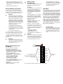
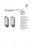
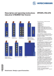
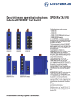
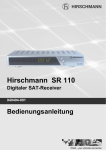
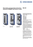
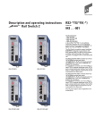
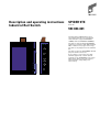
Description and operating instructions
Industrial Rail Switch
SPIDER 5TX
Order No.
943 824-001
The Rail Switch SPIDER 5TX has been
especially designed for use in industrial
environments. It supports ETHERNET
10 MBit/s and Fast ETHERNET 100 MBit/s.
P
x
The devices support switched ETHERNET
networks in accordance with IEEE standard
802.3 or 802.3u using copper technology.
The devices are plugged onto the standard
bar.
The devices have five 10/100 MBit/s twisted
pair ports (RJ45 connectors).
It is possible to connect up to five data
terminal equipments or other network
segments to the 10/100 Mbit/s ports using
twisted pair cabling. The ports support
autonegotiation, autopolarity and
autocrossing.
The performance features described here
are binding only if they have been expressly
guaranteed in the contract. We have
checked that the contents of the technical
publication agree with the hardware and
software described. However, it is not possible to rule out deviations completely, so we
are unable to guarantee complete agreement. However, the details in the technical
publication are checked regularly. Any corrections which prove necessary are contained in subsequent editions. We are grateful
for suggestions for improvement.
z
We reserve the right to make technical
modifications.
Please observe the following:
Permission is not given for the circulation
or reproduction of this document, its use or
the passing on of its contents unless granted expressly. Contravention renders the
perpetrator liable for compensation for
damages. All rights reserved, in particular
in the case of patent grant or registration of
a utility or design.
Note: is an important piece of information
about the product, how to use the product,
or the relevant section of the documentation to which particular attention is to be
drawn.
Certified usage
z
Copyright
© Hirschmann Electronics GmbH & Co. KG 2003
All Rights Reserved
Warning
The device may only be employed
for the purposes described in the
catalog and technical description,
and only in conjunction with external
devices and components recommended or approved by Hirschmann.
The product can only be operated
correctly and safely if it is transported, stored, installed and assembled
properly and correctly. Furthermore,
it must be operated and serviced
carefully.
Safety Guidelines
Shielding Ground
䡺 Beware of possible short circuits when
connecting a cable section with conductive
shielding braiding.
Safety Guidelines Housing
z
We would point out that the content of
these operating instructions is not part of,
nor is it intended to amend an earlier or existing agreement, permit or legal relationship. All obligations on Hirschmann arise
from the respective purchasing agreement
which also contains the full warranty conditions which have sole applicability. These
contractual warranty conditions are neither
extended nor restricted by comments in
these operating instructions.
We would furthermore point out that for
reasons of simplicity, these operating
instructions cannot describe every
conceivable problem associated with the
use of this equipment. Should you require
further information or should particular
problems occur which are not treated in
sufficient detail in the operating instructions, you can request the necessary information from your local Hirschmann sales
partner or directly from the Hirschmann
office (address: refer to chapter entitled
„Notes on CE identification“).
Safety Instructions
This manual contains instructions which
must be observed to ensure your own personal safety and to avoid
damage to devices and machinery. The
instructions are highlighted with a warning
triangle and are shown as
follows according to the degree of endangerment:
z
Danger!
means that death, serious injury or
considerable damage to property
will result if the appropriate safety
measures are not taken.
z
Warning!
means that death, serious injury or
considerable damage to property
can result if the appropriate safety
measures are not taken.
䡺 Switch the basic devices on only when
the case is closed.
z
Warning!
The devices may only be connected
to the supply voltage shown on the
type plate.
The devices are designed for operation with a safety extra-low voltage.
Thus, they may only be connected
to the supply voltage connections
with PELV circuits or alternatively
SELV circuits with the voltage
restrictions in accordance with
IEC/EN 60950.
䡺 For the case where the module is operated with external power supply: Use only a
safety extra-low voltage in accordance with
IEC 950/EN 60 950/VDE 0805 to power the
system.
䡺 First of all you connect the protecting
line, before you establish the further
connections. When you remove connections, you disconnect the protecting line
last.
䡺 Relevant for North America:
The subject unit is to be suppplied by a
Class 2 power source complying with the
requirements of the National Electrical
Code, table 11(b). If power is redundant
supplied (two individual power sources) the
power sources together should comply with
the requirements of the National Electrical
Code, table 11 (b).
䡺 Relevant for North America:
Use 60/75°C or 75°C copper(CU)wire only.
Warning!
Only technicians authorized by
Hirschmann are permitted to open
the housing.
Note: The SPIDER 5TX is grounded via a
pin of the 3pin terminal block.
䡺 Make sure that the electrical installation
meets local or nationally applicable safety
regulations.
z
Warning!
The ventilation slits must not be
covered so as to ensure free air circulation.
The distance to the ventilation slots
of the housing has to be a minimum
of 10 cm.
Never insert pointed objects (thin
screwdrivers, wires, etc.) into the
inside of the subrack! Failure to
observe this point may result in injuries caused by electric shocks.
Safety Guidelines
Power Supply
Note
2
Caution!
means that light injury or damage to
property can result if the appropriate safety measures are not taken.
Note: In accordance with EN 60950, when
installed in residential or business premises
the device may only be operated in fireproof cabinets.
Note: The housing has to be mounted in
upright position.
Safety Guidelines Environment
z
Warning!
The device may only be operated in
the listed ambient temperature
range at the listed relative air humidity (non-condensing).
䡺 The installation location is to be selected so as to ensure compliance with the climatic limits listed in the Technical Data.
䡺 To be used in a Pollution Degree 2 environment only.
Staff qualification
requirements
Note: Qualified personnel, as understood
in this manual and in the warning signs, are
persons who are familiar with the setup,
assembly, startup, and operation of this
product and are appropriately qualified for
their job. This includes, for example, those
persons who have been:
– trained or directed or authorized to
switch on and off, to ground and to label
power circuits and devices or systems in
accordance with current safety engineering standards
– trained or directed in the care and use of
appropriate safety equipment in accordance with the current standards of safety
engineering
7
The devices comply with the regulations of the following European
directive:
– trained in providing first aid.
89/336/EEC
Council Directive on the harmonization of the legal regulations of
member states on electromagnetic
compatibility (amended by Directives 91/263/EEC, 92/31/EEC and
93/68/EEC).
General Safety Instructions
䡺 This device is electrically operated.
Adhere strictly to the safety requirements
relating to voltages applied to the device as
described in the operating instructions!
z
Warning!
Failure to observe the information
given in the warnings could result in
serious injury and/or major damage.
The EU declaration of conformity is
kept available for the responsible
authorities in accordance with the
above-mentioned EU directives at:
Only personnel that have received
appropriate training should operate
this device or work in its immediate
vicinity. The personnel must be fully
familiar with all of the warnings and
maintenance measures in these
operating instructions.
Hirschmann Electronics
GmbH & Co. KG
Automation and Network Solutions
Stuttgarter Straße 45-51
D-72654 Neckartenzlingen
Telephone ++49-7127-14-1480
The product can be used in the residential sphere (residential sphere,
business and trade sphere and small
companies) and in the industrial
sphere.
– Interference immunity:
EN 61000-6-2:2001
– Radio interference level:
EN 55022:1998 + A1 2000 Class A
Correct transport, storage, and
assembly as well as careful operation and maintenance are essential in
ensuring safe and reliable operation
of this device.
Use only undamaged parts!
䡺 These products are only to be used in
the manner indicated in this version of the
”Description and Operating Instructions”.
䡺 Particular attention is to be paid to all
warnings and items of information relating
to safety.
z
Warning!
Any work that may have to be performed on the electrical installation
should be performed by fully qualified technicians only.
Based specifications and
standards:
The devices fulfil the following
specifications and standards:
– EN 61000-6-2:2001 Generic standards –
Immunity for industrial environments
– EN 55022:1998 + A1 2000 – Information
technology equipment –
Radio disturbance characteristics
– EN 60950:1997 – Safety of Information
Technology Equipment (ITE)
– EN 61131-2:1994 + A12 2000 –
Programmable Controllers
– FCC 47 CFR Part 15:2000 –
Code of Federal Regulations
– cUL 508:1998 – Underwriters Labratories
Inc. Safety for Industrial Control
Equipment.
Certified devices are marked with a
certification identifier.
The precondition for compliance
with EMC limit values is strict adherence to the construction guidelines
specified in this description and
operating instructions.
Notes on CE
identification
z
FCC Note:
This equipment has been tested and found
to comply with the limits for a Class A digital device, persuant to part 15 of the FCC
Rules. These limits are designed to provide
reasonable protection against harmful interference when the equipment is operated in
a commercial environment. This equipment
generates, uses, and can radiate radio frequency energy and, if not installed and
used in accordance with the instruction
manual, may cause harmful interference to
radio communications. Operation of this
equipment in a residential area is likely to
cause harmful interference in which case
the user will be required to correct the interference at his own expense.
,
Recycling Note:
After its use, this product has to be
processed as electronic scrap and
disposed of according to the prevailing waste disposal regulations of
your community / district / country /
state.
Warning!
This is a Class A device. This equipment may cause radio interference if
used in a residential area; in this
case it is the operator´s responsibility to take appropriate measures.
3-pin
terminal
block
P
x
P
10/100
Port 5
DA/STAT
10/100
Port 4
DA/STAT
10/100
5 ports 10/100BASE-T(X)
(ports 1 to 5), RJ45 connectors
autonegotiaton, autopolarity,
autocrossing
Port 3
DA/STAT
10/100
LED display
elements
Port 2
DA/STAT
10/100
Port 1
DA/STAT
Fig. 1: Overview interfaces, display elements and controls
3
1. Functional description
The 10/100BASE-T(X) ports of an SPIDER
5TX represent a terminal connection for the
connected LAN segment. You can connect
single devices or complete network
segments.
1.1 FRAME SWITCHING FUNCTIONS
Store and Forward
All data received by the SPIDER 5TX from
the system bus or at the ports are stored
and checked for validity. Invalid and defective frames (> 1.522 byte or CRC error) as
well as fragments (< 64 byte) are discarded.
The SPIDER 5TX forwards the valid frames.
Multi address capability
An SPIDER 5TX learns all source addresses
per port. Only packets with
– unknown addresses
– addresses learnt at this port
– a multi/broadcast address
in the destination address field are sent to
this port.
An SPIDER 5TX learns up to 1,000 addresses. This becomes necessary if more than
one terminal device is connected to one or
more ports. In this way several independent
subnetworks can be connected to an
SPIDER 5TX.
Learnt addresses
An SPIDER 5TX monitors the age of the
learned addresses. The SPIDER 5TX deletes
address entries from the address table
which exceed a certain age (300 seconds).
Note: Restarting deletes the learned
address entries.
Tagging (IEEE 802.1Q)
The IEEE 802.1 Q standard designates the
VLAN tag to be included in a MAC data
frame for the VLAN and prioritizing functions. The VLAN tag consists of 4 bytes (2
bytes tag protocol identifier TPID, 2 bytes
tag control information TCI). It is inserted
between the source address field and the
type field. Data packets with VLAN tag are
transmitted unchanged by the SPIDER 5TX.
1.2 SPECIFIC FUNCTIONS OF THE
TP/TX INTERFACE
Link control
The SPIDER 5TX monitors the connected TP
line segments for short-circuit or interrupt
using regular link test pulses in accordance
with IEEE standard 802.3 10BASE-T/100BASETX. The SPIDER 5TX does not
transmit any data to a TP segment from
which it does not receive a link test pulse.
Note: A non-occupied interface is assessed
as a line interrupt. The TP line to terminal
equipment which is switched off is likewise
assessed as a line interrupt as the deenergised bus coupler cannot transmit link
test pulses.
Auto polarity exchange
If the receive line pair is incorrectly connected (RD+ and RD- switched) polarity is automatically reversed.
Autonegotiation
Autonegotiation is a procedure in which the
switch automatically selects the operating
mode of its 10/100 RJ-45 ports. When a
connection is set up for the first time, the
switch detects the speed (10 or 100 Mbit/s)
and the transmission mode of the connected network (half duplex or full duplex).
Autocrossing
The SPIDER 5TX detects the transmit and
receive pairs (MDI, MDI-X). The SPIDER 5TX
automatically configures its port for the correct transmit and receive pins. Consequently it does not matter whether you connect
devices using a cross-over or straight cable.
1.3 FURTHER FUNCTIONS
AND FEATURES
Reset
The SPIDER 5TX will be reset by the following action:
– input voltages fall below a threshold
After a reset the following action is carried
through:
– initialization
1.4 DISPLAY ELEMENTS
Equipment status
These LEDs provide information about
statuses which affect the function of the
entire SPIDER 5TX.
P – Power (green LED)
– lit:
– supply voltage present
Port Status
These LEDs display port-related
information.
DA/STAT 1 to 5 – Data, Link status
(green LED)
– not lit:
– no valid link
– lit green:
– valid link
– flashes green: – receiving data
10/100 1 bis 5 – Data rate (yellow LED)
– leuchtet nicht: 10 Mbit/s link
– leuchtet yellow: 100 Mbit/s link
1.5 INTERFACES
10/100 MBit/s connection
Five 10/100 Mbit/s Ports (ports 1 to port 5, 8pin R45 sockets) on SPIDER 5TX allow terminal equipment or five independent network segments complying with the standards IEEE 802.3 100BASE-TX / 10BASE-T to
be connected. These ports support autonegotiation and the autopolarity function.
The pin configuration complies with MDI-X.
– Pin configuration of the RJ45 socket:
– 1 line pair: pin 3 and pin 6
– 1 line pair: pin 1 and pin 2
– remaining pins: not used.
n.c.
n.c.
TDn.c.
n.c.
TD+
RDRD+
Pin 8
Pin 7
Pin 6
Pin 5
Pin 4
Pin 3
Pin 2
Pin 1
3pin terminal block
The supply voltage is connected via a 3pin
terminal block.
z
Warning!
The SPIDER 5TX devices are designed for operation with a safety
extra-low voltage. Thus, they may
only be connected to the supply
voltage connections with PELV
circuits or alternatively SELV circuits
with the voltage restrictions in
accordance with IEC/EN 60950.
– Voltage supply: The supply voltage is
electrically isolated from the housing.
– Ground connection: The SPIDER 5TX is
grounded via a pin of the 3pin terminal
block.
+24 V
0V
Fig. 3: Pin configuration of 3pin terminal
block
2. Configuration
2.1 CONNECTING DTE AND OTHER
NETWORK SEGMENTS
It is possible to connect up to five data terminal equipments (DTE) or other network
segments to the 10/100 Mbit/s ports of the
SPIDER 5TX using twisted pair cabling (ref.
Fig. 4).
3. Assembly, startup procedure
and dismantling
3.1 UNPACKING, CHECKING
䡺 Check whether the package was delivered complete (see scope of delivery).
䡺 Check the individual parts for transport
damage.
z
Warning!
Use only undamaged parts!
3.2 ASSEMBLY
The equipment is delivered in a ready-tooperate condition. The following procedure
is appropriate for assembly:
䡺 Pull the terminal block off the SPIDER
5TX and wire up the supply voltage lines.
䡺 Fit the SPIDER 5TX on a 35 mm standard bar to DIN EN 50 022.
䡺 Attach the upper snap-on slide bar of
the SPIDER 5TX to the standard bar and
press it down until it locks in position.
䡺 Fit the signal lines.
Notes:
– The SPIDER 5TX is grounded via a pin of
the terminal block.
– Do not open the housing.
Fig. 2: Pin configuration of an TP interface
4
3.4 DISMANTLING
䡺 To take the SPIDER 5TX off the ISO/DIN
rail, unlock the snap-in mechanism according to Fig 7.
MICE
SPIDER
Fig. 4: Configuration with SPIDER 5TX: Connection of up to 8 data terminal equipments or further segments via TP
– The shielding ground of the twisted pair
lines which can be connected is electrically connected to the ground connection.
23
Fig. 7: Dismantling the SPIDER 5TX
63,3
4. Further support
13,7
In the event of technical queries, please talk
to the Hirschmann contract partner responsible for looking after your account or
directly to the Hirschmann office. You can
find the addresses of our contract partners
– on the Internet
(http://www.hirschmann.de).
70
8,5
Our support line is also at your disposal:
Tel. +49(1805) 14-1538
Fax +49(7127) 14-1551
Fig. 6: Dimensions
Fig. 5: Assembling the SPIDER 5TX
3.3 STARTUP PROCEDURE
䡺 You start up the SPIDER 5TX by connecting the supply voltage via the 3-pin terminal block.
Answers to Frequently Asked Questions can
be found on the Hirschmann internet site
www.hirschmann.de
The FAQs are located under „Service“ in
the Automation and Network Solutions
section.
www.hicomcenter.com gives you an up-todate overview of training courses about
technology and products.
5. Technical data
General data
Operating voltage
Buffer time
NEC Class 2 power source 24 VDC (-25% +33%) safety extra-low voltage (SELV/PELV)
5 A maximum
min. 10 ms at 24 VDC
Potential difference between input
voltage and housing
Potential difference to input voltage, +24 VDC: 32 VDC
Potential difference to input voltage, ground: -32 VDC
Current consumption at 24 VDC
Overload current protection at input
Dimensions W x H x D
Weight
Ambient temperature
Storage temperature
Humidity
Atmospheric pressure
Pollution Degree
Protection type
2.9 W maximum
non-changeable fuse
25 mm x 100 mm x 78.5 mm
110 g
0 ºC to + 60 ºC
- 40 ºC to + 70 ºC
up to 95% (non condensing)
min. 79 kPa
2
IP 30
1 in x 4 in x 3.1 in
0.24 lb
32 ºF to 140 ºF
-32 ºF to 158 ºF
5
Interference proof
Discharge of static electricity
Contact discharge
Air discharge
Electromagnetic fields
Fast transients
Surge voltage symmetrical
Surge voltage asymmetrical
Cable-based RF faults
EN 61000-4-2 Test level 2
EN 61000-4-2 Test level 3
EN 61000-4-3 Test level 3
EN 61000-4-4 Test level 3
EN 61000-4-5 Test level 2
EN 61000-4-5 Test level 3
EN 61000-4-6 Test level 3
EMC emitted immunity
EN 55022
FCC 47 CFR Part 15
Class A
Class A
Stability
Vibration
Shock
IEC 60068-2-6 Test FC, testing level in line with IEC 61131-2 E2 CDV and
IEC 60068-2-27 Test Ea, testing level in line with IEC 61131-2 E2 CDV
Certifications
cUL 508 / CSA 22.2 No.142
pending
Network size
TP port 10BASE-T/100BASE-TX
Length of a twisted pair segment
100 m (328 ft) maximum
Interfaces
5 TP ports
RJ45 sockets, 10/100 MBit/s
Displays
Equipment status
Port status
1 x green LED
5 x green LEDs
5 x yellow LEDs
P – power, supply voltage present
DAT/STAT – data, link status
10/100 – Data rate
Scope of delivery
Rail Switch SPIDER 5TX incl.
Order number
Rail Switch SPIDER 5TX
terminal block for supply voltage
description and operating instructions
943 824-001
Accessories
ETHERNET manual
Manual
Basics i ETHERNET and TCP/IP
Rail Power Supply RPS 30
Rail Power Supply RPS 60
Rail Power Supply RPS 120
Hirschmann Electronics GmbH & Co. KG
Automation and Network Solutions
Stuttgarter Straße 45-51
D-72654 Neckartenzlingen
Germany
Tel.: ++49 / 1805 / 14-1538
Fax: ++49 / 7127 / 14-1551
E-Mail: [email protected]
Internet: http://www.hirschmann.com
Printed in Germany
Subject to alterations
943 320-011
280 720-834
943 662-003
943 662-001
943 662-011
JBC-electronic
ul. Pilsudskiego 73
67-100 Nowa Sol
Contact Person: Mr. Artur Rola
Telephone.: +48 68 356 09 90
356 09 93
Fax:
+48 68 356 09 95
E-mail: [email protected]
www.jbc.com.pl
039669001010703000
Hirschmann. Solutions for communication.
Germany
Hirschmann Electronics GmbH & Co. KG
Automation and Network Solutions
Stuttgarter Straße 45-51
D-72654 Neckartenzlingen
Postfach 1649
D-72606 Nürtingen
Tel +49-7127-14-1479/-1480
Fax +49-7127-14-1495/-1496/-1502
e-mail: [email protected]
http://www.hirschmann.com
Austria
Hirschmann Austria GmbH
Oberer Paspelsweg 6-8
A-6830 Rankweil-Brederis
Tel +43-55 22 307-0
Fax +43-55 22 307-555
e-mail: [email protected]
Switzerland
Hirschmann Electronics GmbH & Co. KG,
Neckartenzlingen
Zweigniederlassung Uster
Seestraße 16
CH-8610 Uster
Tel +41-1-905 82 82
Fax +41-1-905 82 89
e-mail: [email protected]
France
Hirschmann Electronics S.A.
24, rue du Fer à Cheval, Z.I.
F-95200 Sarcelles
Tel +33-1-39 33 02 80
Fax +33-1-39 90 59 68
e-mail: [email protected]
Great Britain
Hirschmann Electronics Ltd.
St. Martins Way
St. Martins Business Centre
GB-Bedford MK42 OLF
Tel +44-1234-34 59 99
Fax +44-1234-35 22 22
e-mail: [email protected]
Printed in Germany.
Hirschmann Electronics GmnH & Co. KG
assumes no responsibility for any errors
which may appear in this document.
Netherlands
Hirschmann Electronics B.V.
Pampuslaan 170
1382 JS WEESP
Postbus 92
NL-1380 AB Weesp
Tel +31-2944-6 25 55
Fax +31-2944-8 06 39
e-mail: [email protected]
Spain
Hirschmann Electronics S. A.
Calle Trespaderne, 29
Edifico Barajas I, 2a Planta
E-28042 Madrid
Tel +34-91-74 61 7 30
Fax +34-91-74 61 7 35
e-mail: [email protected]
Hungary
Hirschmann Electronics Kft.
Rokolya u. 1-13
H-1131 Budapest
Tel +36-1-349 41 99
Fax +36-1-329 84 53
e-mail: [email protected]
USA
Hirschmann Electronics Inc.
30 Hook Mountain Road – Unit 201
Pine Brook, New Jersey 07058, USA
Tel +1-973-830 2000
Fax +1-973-830 1470
e-mail: [email protected]
Singapore
Hirschmann Electronics Pte. Ltd.
3 Toh Tuck Link
#04-01 German Districentre
Singapore 596228
Tel +65-64 63 58 55
Fax +65-64 63 57 55
e-mail: [email protected]
JBC-electronic
ul. Pilsudskiego 73
67-100 Nowa Sol
Contact Person: Mr. Artur Rola
Telephone.: +48 68 356 09 90
356 09 93
Fax:
+48 68 356 09 95
E-mail: [email protected]
www.jbc.com.pl