1
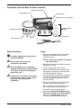
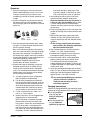
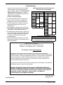
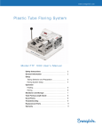
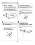
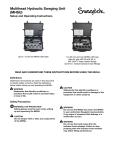
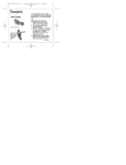
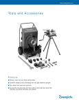
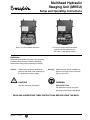
Multihead Hydraulic
Swaging Unit (MHSU)
Setup and Operating Instructions
Up to 1 in./25 mm MHSU with base
1 in./25 mm and over MHSU with base
(also for use with 5/8 and 3/4 in.
SAF 2507TM super duplex fittings)
Definitions
Statements and symbols are used in this document
to identify safety concerns. Read the definitions
below before setting up and operating the MHSU.
Caution:
Statements that identify conditions or
practices that could result in damage to
the equipment or other property.
CAUTION!
Indicates cautionary information.
Warning:
Statements that identify conditions or
practices that could result in personal
injury or loss of life.
WARNING!
EYE PROTECTION
Eye protection must be worn while
operating or working near the MHSU.
READ AND UNDERSTAND THESE INSTRUCTIONS BEFORE USING THE MHSU.
MS-12-37
Revision 2 12-02-CP
Components (Unit with Body Die Heads and Base)
Hydraulic hand pump
Pump bypass valve
Indicator knob
Retaining ring & Locating pin
Gap inspection
gauges
Chamfer blocks
Safety glasses
Base
Die heads
MHSU hydraulic housing
Retaining
ring pliers
Safety Precautions
Use
safety glasses when setting up and
operating the MHSU.
Do
not tamper with or alter any
components of the MHSU.
Return
the MHSU to your independent
Swagelok sales and service representative
if any signs of hydraulic fluid leakage or
malfunction occur.
Pumping
after the indicator knob releases
may cause over-swaging, which causes
the tube to stick and may affect
gaugeability.
2
Setup
1. Remove the retaining ring from the hydraulic
housing of the MHSU body by using the
retaining ring pliers.
Use caution when releasing the retaining
ring from the pliers.
2. Remove the previously installed die head from
the hydraulic housing.
3. Select the appropriate size die head.
4. Check the die head piston for movement by
depressing the piston before inserting the die
head into the hydraulic housing.
5. Insert the selected die head into the hydraulic
housing and align the notch on the die head
with the corresponding locating pin on the
hydraulic housing.
6. Reinstall the retaining ring into the hydraulic
housing using the retaining ring pliers.
Note: Visually verify that the retaining ring is
fully inserted into the hydraulic housing.
7. The MHSU is now ready for operation.
8. Refer to the Recommended Minimum Wall
Thickness of Tubing for use with the MHSU
table in the Troubleshooting section for
information on recommended tubing size.
MS-12-37
Revision 2 12-02-CP
Operation
1. Open the pump bypass valve by turning the
handle counterclockwise at least 1/2 to 1 turn.
It may be necessary to first close the valve
completely by turning the handle clockwise until
it stops.
2. Install the Swagelok nut and ferrules onto the
die head in the order and orientation shown
until finger-tight and all die threads are covered
by the nut.
Nut
Back
ferrule
Front
ferrule
Die
head
3. Push the indicator knob forward until it snaps
into place. The knob shoulder should be flush
with the hydraulic housing.
Note: If the indicator knob does not snap into
place or is not flush with the housing the piston
may not be fully retracted. This problem may
be caused by the bypass valve being closed or
by the piston binding. Do not proceed until unit
is functioning properly. Contact your
independent Swagelok sales and service
representative for further assistance.
4. Prepare tube ends by deburring or using the
Swagelok chamfer block (as follows and as
shown on the instruction decal in the MHSU
case). The chamfer block procedure should be
followed when using the up to and including
one inch tubing on the MHSU.
A. Cut tubing squarely. Use of a Swagelok
tube saw guide is recommended.
B. For up to and including one inch MHSU,
use the chamfer blocks provided. Insert cut
end of tubing in to the chamfer block and
while firmly holding the tubing, strike the
chamfer block with a hammer to coin the
end (as shown on the instruction decal).
C. If a file is used on the OD, make a 10° x
0.06 in. (1.5 mm) chamfer.
D. Remove any burrs. Use of Swagelok tube
deburring tools is recommended.
NOTE: Deburring is important for proper
fitting function as well as for clean, leakfree systems. If burrs are not removed from
the OD of the tube, it could prevent the
tube from being fully inserted through the
nut, ferrules or against the shoulder of the
fitting body. ID burrs could also break off
MS-12-37
Revision 2 12-02-CP
and cause damage in other parts of the
system by lodging in small holes or vents,
or by scratching valve seats or soft seals.
5. Insert tubing into the nut until it rests firmly
against the piston shoulder. Refer to the
Recommended Minimum Wall Thickness of
Tubing for Use with the MHSU table on page
4. Use of tubing below the recommended
minimum wall may result in the tube sticking in
the die head.
6. Close the pump bypass valve to the finger-tight
position by rotating valve handle clockwise until
it stops.
7. While holding the tubing against the piston
shoulder, increase the hydraulic pressure by
using the hand pump until the indicator knob is
released.
Do not keep pumping after the indicator
knob releases. Stop pumping immediately
after the indicator knob pops.
8. Open the pump bypass valve by turning the
handle 1/2 to 1 turn counterclockwise.
9. Unthread the Swagelok nut, and remove the
preswaged assembly from the housing.
10. Inspect the tube end for a radial indentation
bottom marking (see decal in MHSU case).
This indentation indicates the tubing was
properly bottomed in the MHSU. If there is not
a visible indentation, the preswaged assembly
should not be used.
11. Install the preswaged assembly into the fitting
body. Turn the nut onto the fitting body until it is
finger-tight. Hold the fitting body stable and
tighten the nut 1/2 turn with a wrench.
Use the Swagelok MHSU gap inspection
gauge to assure the installer or
inspector that the fitting has been
sufficiently tightened.
Gauging Instructions
Position the Swagelok MHSU gap inspection gauge
adjacent to the gap between the nut and body hex.
■ If the gauge will not
enter the gap, the
fitting is sufficiently
tightened.
■ If the gauge will enter
the gap, additional
tightening is required.
3
Troubleshooting
1. If tubing is difficult to remove from the MHSU
after preswaging, rock the tubing back and
forth to remove it. Refer to the Recommended
Minimum Wall Thickness table—swaging
tubing below the recommended minimum wall
may result in tube sticking.
Do not rotate the tubing.
2. If the indicator knob does not release or oil is
leaking, return the unit to your independent
Swagelok sales and service representative.
3. If the die head piston is binding, contact your
independent Swagelok sales and service
representative.
4. If the Swagelok nut does not cover all of the die
head threads, verify that the bypass valve is open
and the piston is not binding in the body die.
5. If the pump fails to build pressure, check the oil
level in the pump by removing the dipstick and
checking for a proper amount of oil. Too much
or too little oil will prevent the pump from
operating properly.
6. The pump manufacturer specifies using 10W,
AW-46 grade hydraulic oil or equivalent with an
antifoaming additive.
Recommended Minimum Wall Thickness of
Tubing for use with the MHSU
Fractional Tubing
MHSU
Size
in.
Steel
in.
1/2
0.049
5/8
3/4
7/8
1 1/2
2
Metric Tubing
MHSU
Size
mm
Steel
mm
Stainless
Steel
mm
12
0.065
0.065
1
1 1/4
Stainless
Steel
in.
14
15
1.5
1.5
16
0.083
0.083
0.095
0.095
0.109
1.8
18
20
22
2.0
2.0
25
28
30
32
2.2
2.2
38
2.5
50
SAF 2507 Super Duplex Fittings
1/4 through 1/2 in. fittings—not approved for use with the MHSU
5/8 and 3/4 in. fittings—use 1 in./25 mm and over MHSU
with appropriate 5/8 and 3/4 in. super duplex dies
SWAGELOK COMPANY
29500 Solon Road, Solon, Ohio 44139-3492 U.S.A.
Telephone: +1.440.248.4600 FAX: +1.440.349.5970
The Swagelok Limited Lifetime Warranty
Swagelok hereby warrants to the purchaser of this Product that the nonelectrical
components of the Product shall be free from defects in material and workmanship for the
life of the Product. All electrical components installed in or on the Product are warranted to
be free from defects in material and workmanship for twelve months from the date of
purchase. Manufacturer shall be liable only if the Product is used as specified in the
current catalogs and written instructions.
The purchaser’s remedies shall be limited to replacement and installation of any parts that
fail through a defect in material or workmanship.
MANUFACTURER SPECIFICALLY DISAVOWS ANY OTHER REPRESENTATION,
EXPRESS OR IMPLIED, WARRANTY, OR LIABILITY RELATING TO THE CONDITION
OF USE OF THE PRODUCT, AND IN NO EVENT SHALL SWAGELOK BE LIABLE TO
PURCHASE, OR ANY THIRD PARTY, FOR ANY DIRECT OR INDIRECT
CONSEQUENTIAL OR INCIDENTAL DAMAGES.
www.swagelok.com
4
Swagelok—TM Swagelok Company
SAF 2507—TM Sandvik AB
© 2002 Swagelok Company
Printed in U.S.A
MS-12-37
Revision 2 12-02-CP