1
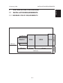
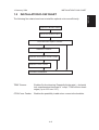
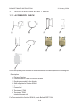
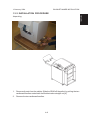
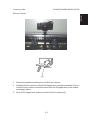
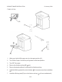
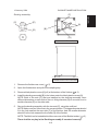
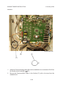
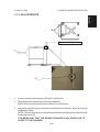
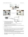
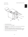
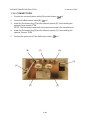
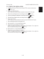
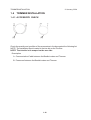
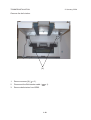
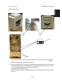
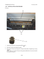
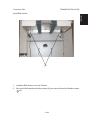
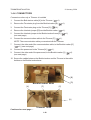
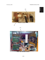
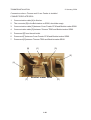
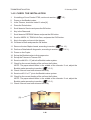
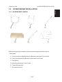
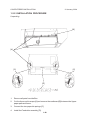
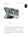
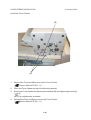
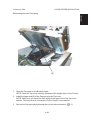
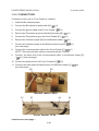
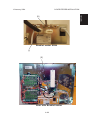
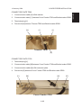
INSTALLATION MANUAL
SR90 / SR90+ SYSTEM
January 12, 2004
Subject to change
Page intentionally blank
IMPORTANT SAFETY NOTICES
PREVENTION OF PHYSICAL INJURY
Always connect the equipment to a
properly grounded power source. In doubt,
have the power source checked by a qualified electrician.
WARNING: Improper connection of the
equipment grounding conductor can result
in electrical shock.
Always follow all warnings marked on, or
supplied with, the equipment.
Always locate the equipment on a solid
support surface with adequate strength for
the weight of the machine.
Always exercise care in moving or
relocating the equipment.
Always keep magnets and all devices with
strong magnetic field away from the
machine.
Never use a ground adapter plug to
connect the equipment to a power source
that lacks a ground connection terminal.
Never attempt any maintenance function
that is not specifically described in this
documentation.
Never remove the covers or guards that
are fastened with screws.
Never install the unit near a radiator or any
other heat source.
Never override or “cheat” electrical or
mechanical interlock devices.
Never operate the equipment if you notice
unusual noises or odours. Disconnect the
power cord from the power source and call
your customer service engineer to correct
the problem.
1. Before disassembling or assembling parts of the Booklet maker and peripherals.
make sure that the Booklet maker power cord is unplugged,
2. The wall outlet should be near the Booklet maker and easily accessible.
3. Note that some components of the Booklet maker and peripherals are supplied
with electrical voltage even if the main power switch is turned off.
4. If any adjustment or operation check has to be made with exterior covers off or
open while the main switch is turned on, keep hands away from electrical or
mechanically driven components.
OBSERVANCE OF ELECTRICAL SAFETY STANDARDS
1. The Booklet maker and its peripherals must be installed and maintained by a
customer service representative who has completed the training course on those
models.
SAFETY AND ECOLOGICAL NOTES FOR DISPOSAL
1.
Dispose of replaced parts in accordance with local regulations.
Page intentionally blank
INSTALLATION REQUIREMENTS
1.
INSTALLATION PROCEDURE
1.1
INSTALLATION REQUIREMENTS
Installation
12 January, 2004
1.1.1 MINIMUM SPACE REQUIREMENTS
Stacker
TR90
SR90
CF90
640 mm
Rail
600 mm
350 mm
1690 mm
1- 1
740 mm
555 mm
400 mm
INSTALLATION REQUIREMENTS
12 January, 2004
1.1.2 POWER REQUIREMENTS
CAUTION
1. Make sure that the wall outlet is near the main machine and easily
accessible. Make sure the plug is firmly inserted in the outlet.
2. Avoid multi-wiring.
3. Be sure to ground the machine.
1. Input voltage level:
North America 115V, 50Hz/60Hz: More than 3 A.
Europe/Asia 230V, 50Hz/60Hz: More than 1.5 A.
2. Permissible voltage fluctuation: ± 10%
3. Never set anything on the power cord.
1- 2
12 January, 2004
INSTALLATION FLOW CHART
The following flow chart shows how to install the optional units more efficiently.
Unpack the Booklet maker
Install the Booklet maker
Does the user require Trimmer
Yes
No
Install the Trimmer
Does the user require Cover Feeder
Yes
No
Install the Cover Feeder
Check the Installation
TR90 Trimmer:
Enables On-line trimming. Especially thicker sets ( > 4 sheets)
look unprofessional because of ”creep”. TR90 will trim those
edges ( up to 12.5 mm / 1/2”).
CF90 Cover Feeder:
Enables the possibility to add colour covers to the booklets.
1- 3
Installation
1.2
INSTALLATION FLOW CHART
BOOKLET MAKER INSTALLATION
1.3
12 January, 2004
BOOKLET MAKER INSTALLATION
1.3.1 ACCESSORY CHECK
[A]
[B]
[E]
[C]
[D]
[G]
[F]
[H]
[I]
Check the quantity and condition of the accessories in the box against the following list:
Description
A.
B.
C.
D.
E.
F.
G.
H.
I.
Exit arm Catcher
Communication Cable for finisher SR840
Docking assembly for the finisher
Shift tray plate for finisher SR840
Exit tray plate
Powercord
Terminator CF90
Terminator TR90
Interlock Jumper (x2)
For Conversion kit to finisher SR810, check Bulletin RZP7 001.
1- 4
12 January, 2004
BOOKLET MAKER INSTALLATION
Installation
1.3.2 INSTALLATION PROCEDURE
Unpacking
1.
Remove all parts from the pallets. Slide the SR90 off the pallet, by pulling the two
cardboard handles underneath the Booklet maker straight out [A].
2.
Remove the two cardboard handles.
1- 5
BOOKLET MAKER INSTALLATION
12 January, 2004
Panels and Shelf
[A]
[B]
[C]
1.
Loosen [A] (
2.
Slide the top of the Panels [B] away from the screws. Remove the Panels and the
Shelf [C].
x 4) .
1- 6
12 January, 2004
BOOKLET MAKER INSTALLATION
Installation
Exit arm catcher
[A]
1.
Remove the adhesive backing from the Exit arm catcher.
2.
Install the Exit arm catcher so that the Exit paper arm is as high as possible. The nut
on the Exit arm catcher should be centred over the Exit paper arm on the finisher,
according to figure.
3.
lift up the Exit paper arm, and set it onto the Exit arm catcher [A].
1- 7
BOOKLET MAKER INSTALLATION
12 January, 2004
Copier exit tray
[A]
[C]
[D]
[B]
1.
Make sure that the Exit paper arm is in the upper position [A].
2.
Turn ON the Copier, the shift tray will go down to the lower position.
3.
Turn OFF the copier.
4.
Remove the finisher exit tray [B] (
5.
Remove the plastic deflector, underneath the finisher exit tray.
6.
Install the Shift tray plate [C] on to the finisher (
kit)
7.
Install the Exit tray plate [D] on to the finisher exit tray (
x 4).
1- 8
x 4 counter screws from installation
x 4 from installation kit).
12 January, 2004
BOOKLET MAKER INSTALLATION
[F]
[C]
Installation
Docking assembly
[E]
[A]
[D]
[B]
[G]
Finisher seen from above
Finisher seen from front side
1.
Remove the finisher rear cover (
x 2).
2.
Open the finisher door and pull out the stapling tray.
3.
Remove black plastic covers [A] (x2) at the bottom of the finisher (
4.
Install the docking assembly [B] in the holes under the black plastic covers [A].
NOTE: Both of the nuts [C], that are installed on the docking assembly, have
different diameters on each side of the nut. A big diameter [D] on one side, and a
smaller diameter [E] on the other side.
5.
Secure the docking assembly with the two nuts [C], using the multi tool.
NOTE: Make sure you fit the nuts in the correct position. The bigger diameter should
fit in the hole nearest the rear side [F] of the finisher. And the smaller diameter
should fit in the hole nearest the front side [G] of the finisher.
x 2).
NOTE: The Multi tool is located behind the rear cover of the Booklet maker (
There shall be no play in the Docking assembly if mounted correctly.
1- 9
x 3).
BOOKLET MAKER INSTALLATION
12 January, 2004
Interface
Finisher Main PCB
[B]
[A]
[C]
1.
Install the Communication cable [A] from the installation kit, to connector CN132 on
the finisher main board [B] (
x1).
2.
Secure the Communication cable in the finisher [C], with a tie wrap from the
installation kit.
1- 10
12 January, 2004
BOOKLET MAKER INSTALLATION
Installation
1.3.3 ADJUSTMENTS
[B]
Finisher seen from above
[C]
1.
Loosen the two positioning pins [B] with the Multi tool.
2.
Dock the Booklet maker to the Docking assembly.
NOTE: Make sure that the Exit arm catcher have clearance.
3.
Adjust the gap between the infeeder assembly and the finisher. Adjust by moving
the Booklet maker.
NOTE: The two black studs on the infeeder assembly should just have contact with
the finisher cover [C].
IT IS IMPORTANT THAT THE BOOKLET MAKER IS NOT INSTALLED TO
CLOSE TO THE FINISHER.
1- 11
BOOKLET MAKER INSTALLATION
12 January, 2004
[A]
[C]
[D]
4.
Adjust the distance between the front
of the Booklet maker Infeeder, and
the front of the finisher panel. Adjust
[B]
by moving the Booklet maker.
NOTE: The distance should be within the first cut out [A] on the Multi tool.
5.
Tighten the two positioning pins, with the Multi tool.
NOTE: Before tightening the two positioning pins, make sure that both adjustments
are correct.
6.
If installing a Rail. Install it now.
7.
Remove the front cover by loosening two screws, and removing two screws (
8.
Adjust the height on the Booklet maker. Adjust by turning the four nuts [B] on the
Booklet maker with the Multi tool (one revolution on the nuts is 2 mm / 5/64” in
height). Adjust on front side and rear side.
NOTE: Place the Multi tool on the infeeder of the Booklet maker, make sure that it
is not placed on the manual feed guides. The distance should be within the second
cut out (119 mm / 4 11/16”) on the Multi tool [C], according to figures.
x4).
The distance on the right side, and the left side of the Booklet maker should
be equal [D].
1- 12
12 January, 2004
BOOKLET MAKER INSTALLATION
Installation
Panels and Shelf
[E]
[D]
[B]
[C]
[A]
1.
Undock the Booklet maker.
2.
Reinstall the front and rear cover (
3.
Slide the front [A] and rear [B] panels in place, with the bottom first onto the docking
assembly [C].
4.
Put the shelf between the panels. Make sure to turn the shelf correct.
NOTE: The cut out [D] should be away from the Booklet maker, NOT TOWARDS.
5.
Slide the top of the panels under the screws on the infeeder, tighten [E] (
6.
Take the finisher exit tray and put it on the shelf [D].
x 7).
1- 13
x 4) .
BOOKLET MAKER INSTALLATION
12 January, 2004
1.3.4 CONNECTORS
1.
Connect the communication cable [A] from the finisher (
2.
Connect the Belt stacker cable [B] (
3.
Install the Terminator plug [C] and the Interlock jumper [E], If not installing the
optional Cover feeder CF90.
NOTE: The Terminators and Interlock jumpers are stored in the installation kit.
4.
Install the Terminator plug [D] and the Interlock jumper [F], If not installing the
optional Trimmer TR90.
5.
Connect the powercord [G] to the Booklet maker (
[B]
x1).
x1).
[C]
x1).
[D]
[G]
[A]
[E]
[F]
1- 14
12 January, 2004
BOOKLET MAKER INSTALLATION
1.
If installing a Trimmer TR90 or Cover Feeder CF90, continue to that section
(
1.4 or 1.5 ).
2.
Power on the Booklet maker.
NOTE: Make sure that the finisher connector is connected to the copier.
3.
Remove the two Stapler heads, according to section (
4.
Perform a Detailed self-diagnostic, according to section (
5.
Reinstall the two Stapler heads, according to section (
6.
Power on the Copier.
NOTE: Make sure that the Booklet maker is powered ON before the Copier.
7.
Set up the Booklet maker to Auto paper size.
8.
Send one A4/8.5 x 11” job to the Booklet maker.
9.
Check for the correct feeding of the paper.
NOTE: The paper should enter in the middle of the infeeder. If not, adjust the
Booklet maker according to section (
1.3.3 ).
3.4.12 ).
5.3.3 )
3.4.12 ).
10. Send one A3/11 x 17” job to the Booklet maker.
11. Check for the correct feeding of the paper.
NOTE: The paper should enter in the middle of the infeeder. If not, adjust the
1.3.3 ).
Booklet maker according to section (
1- 15
Installation
1.3.5 CHECK THE INSTALLATION
TRIMMER INSTALLATION
1.4
12 January, 2004
TRIMMER INSTALLATION
1.4.1 ACCESSORY CHECK
[A]
[B]
Check the quantity and condition of the accessories in the box against the following list:
NOTE: The Installation Box is located in the trim bin on the Trimmer.
NOTE: The trim bin is tie wraped on the rear side.
Description
A. Communication Cable between the Booklet maker and Trimmer
B. Powercord between the Booklet maker and Trimmer
1- 16
12 January, 2004
TRIMMER INSTALLATION
Installation
1.4.2 ADJUSTMENTS
Unpacking
1.
Remove all parts from the pallets.
2.
Ensure all of the packing material is removed from the outside of the Trimmer.
1- 17
TRIMMER INSTALLATION
12 January, 2004
Remove the belt stacker
[A]
1.
Remove screws [A] (
x 2 ).
2.
Disconnect the Belt stacker cable (
3.
Remove belt stacker from SR90.
x 1).
1- 18
12 January, 2004
TRIMMER INSTALLATION
Installation
Height adjustment
[B]
[C]
[E]
[D]
1.
Remove the front cover by loosen two screws, and removing two screws (
2.
Move the Trimmer up to the Booklet maker.
3.
Adjust the height on the Trimmer, so that the docking bracket [B] on the Trimmer fits
in the docking hole [C] on the Booklet maker (one revolution on the nuts is 1,5mm /
1/16” in height). Adjust by turning the four nuts [D] on
the Trimmer with the caster tool.
NOTE: Make sure that the Ground plate on the docking bracket [B], is grounded
correctly.
1- 19
x 4).
TRIMMER INSTALLATION
12 January, 2004
1.4.3 INSTALLATION PROCEDURE
Docking
[B]
[A]
[C]
x 2).
1.
Loosen nuts [A] to the Locking bracket [B] (
2.
Dock the Trimmer to the Booklet maker.
3.
Secure the Trimmer by lifting the Locking bracket [B] and tightening nuts [A]
(
x 2).
NOTE: Make sure that the Trimmer locking bracket [B] locks in the outer slots [C]
on the positioning pins.
1- 20
12 January, 2004
TRIMMER INSTALLATION
Installation
Install Belt stacker
[A]
1.
Install the Belt stacker on to the Trimmer.
2.
Secure the Belt stacker with the screws [A] you removed from the Booklet maker
( x 2).
1- 21
TRIMMER INSTALLATION
12 January, 2004
1.4.4 CONNECTORS
Connectors when only a Trimmer is installed
1.
Connect the Belt stacker cable [A] to the Trimmer (
x1).
2.
Remove the Terminator plug from the Booklet maker [B] (
3.
Connect the Terminator plug on the Trimmer [C] (
4.
Remove the Interlock jumper [D] from the Booklet maker (
5.
Connect the Interlock jumper to the Booklet maker frame [E] (
(see next page)
6.
Connect the communication cable to the Trimmer [F] (
x1).
NOTE: The communication cable you received with the Trimmer.
7.
Connect, the other end of the communication cable, to the Booklet maker [G]
x1). (see next page)
(
8.
Connect the powercord to the Trimmer [H] (
9.
Connect, the other end of the powercord, to the Booklet maker [ I ] (
(see next page)
x1).
x1).
x1).
x1).
x1).
x1).
10. Secure the cables between the Booklet maker and the Trimmer in the cable
holders on the Booklet maker base.
[B]
[D]
Booklet maker SR90
[A]
[F]
[C]
[H]
Continued on next page....
Trimmer TR90
1- 22
TRIMMER INSTALLATION
[G]
Booklet maker SR90
[I]
[E]
Rear side Booklet maker
1- 23
Installation
12 January, 2004
TRIMMER INSTALLATION
12 January, 2004
Connectors when a Trimmer and Cover Feeder is installed
CONNECTOR PLATE SR90
1.
Communication cable [A] to finisher.
2.
The connector [B] to the Belt stacker on SR90, should be empty.
3.
Communication cable [C] between Cover Feeder CF90 and Booklet maker SR90.
4.
Communication cable [D] between Trimmer TR90 and Booklet maker SR90.
5.
Powercord [E] from the wall outlet.
6.
Powercord [F] between Cover Feeder CF90 and Booklet maker SR90.
7.
Powercord [G] between Trimmer TR90 and Booklet maker SR90.
[B]
[C]
[D]
[E]
[A]
[F]
Booklet maker SR90
1- 24
[G]
12 January, 2004
TRIMMER INSTALLATION
1.
Communication cable [H] to Belt stacker.
2.
Communication cable [ I ] between Cover Feeder CF90 and Booklet maker SR90.
3.
Terminator plug [J].
4.
Powercord [K] between Trimmer TR90 and Booklet maker SR90.
[H]
[I]
[J]
Trimmer TR90
[K]
CONNECTOR PLATE CF90
1.
Terminator plug [L].
2.
Communication cable [M] between Cover Feeder CF90 and Booklet maker SR90.
3.
Communication cable [N] to Bin extension plate.
4.
Powercord [O] between Cover Feeder CF90 and Booklet maker SR90.
[L]
[M]
[N]
Cover Feeder CF90
1- 25
[O]
Installation
CONNECTOR PLATE TR90
TRIMMER INSTALLATION
12 January, 2004
1.4.5 CHECK THE INSTALLATION
1.
If installing a Cover Feeder CF90, continue to section (
1.5 ).
2.
Power on the Booklet maker.
3.
In the Trimmer, check the Index 16 value [A].
4.
Press the Tools button.
5.
Scroll down to Service and press the OK button.
6.
Key in the Password.
7.
Scroll down to EEPROM Values and press the OK button.
8.
Scroll to INDEX 16, TR90.Knife Zero, and press the CHG button.
9.
Key in the value you have in the trimmer.
10. Go down to Store and press the OK button.
11. Remove the two Stapler heads, according to section (
12. Perform a Detailed self-diagnostic, according to section (
3.4.12 ).
5.3.3 ).
13. Power on the Copier.
14. Set up the Booklet maker to Auto paper size.
15. Set up the Trimmer to Trimmer ON.
16. Send one A4/8.5 x 11” job to the Booklet maker system.
17. Check for the correct feeding of the set from the finisher.
NOTE: The paper should enter in the middle of the infeeder. If not, adjust the
Booklet maker according to section (
1.3.3 ).
18. Check if the set have been trimmed correctly.
19. Send one A3/11 x 17” job to the Booklet maker system.
20. Check for the correct feeding of the set from the finisher.
NOTE: The paper should enter in the middle of the infeeder. If not, adjust the
Booklet maker according to section (
1.3.3 ).
21. Check if the set have been trimmed correctly.
[A]
1- 26
12 January, 2004
COVER FEEDER INSTALLATION
Installation
1.5
COVER FEEDER INSTALLATION
1.5.1 ACCESSORY CHECK
[A]
[C]
[B]
[D]
[E]
[F]
Check the quantity and condition of the accessories against the following list:
Description
A. Communication Cable between the Booklet maker and Cover Feeder
B. Powercord between the Booklet maker and Cover Feeder
C. Gas Spring
D. Mounting bracket for Cover Feeder
E. Feed roller assembly
F. Bin extension plate
1- 27
COVER FEEDER INSTALLATION
12 January, 2004
1.5.2 INSTALLATION PROCEDURE
Unpacking
[B]
[A]
[C]
[C]
[D]
1.
Remove all parts from the Box.
2.
Cut the three red tie wraps [A] and remove the cardboard [B] between the Upper
paper path and frame.
3.
Connect the two paper bin springs [C].
4.
Install the Feed roller assembly [D].
1- 28
12 January, 2004
COVER FEEDER INSTALLATION
Installation
Install mounting bracket
[B]
[A]
1.
x 2 ).
Remove the nuts [A] to the Gas spring in the Booklet maker (
NOTE: Make sure you notice the orientation of the Gas spring, before removing it.
2.
Install the lower end of the new and shorter Gas spring, from the installation kit, to
the black bracket in Booklet maker (
x 1 ).
3.
Remove the stainless plate on the Top cover by removing nuts [B] (
4.
Install the Mounting bracket where you removed the stainless plate (
5.
Remove the four nuts and two brackets on the top side of the Mounting bracket
(
x 4, brackets x 2 ).
1- 29
x 2 ).
x 2 ).
COVER FEEDER INSTALLATION
12 January, 2004
Install the Cover Feeder
[B]
[A]
1.
Remove the Front and Rear cover on the Cover Feeder
Service Manual CF90 1.1.1 ).
(
2.
Place the Cover Feeder on top of the Mounting bracket.
3.
Secure the Cover Feeder by replacing the brackets [B], and tightening the nuts [A]
(
x 4).
NOTE: No adjustments is needed.
4.
Reinstall the Front and Rear cover on the Cover Feeder
(
Service Manual CF90 1.1.1 ).
1- 30
12 January, 2004
COVER FEEDER INSTALLATION
Installation
Reinstalling the new Gas spring
[A]
1.
Open the Top cover on the Booklet maker.
NOTE: Open the Top cover carefully, because of the weight of the Cover Feeder.
2.
Install the upper end [A] of the Gas spring to the Top cover.
NOTE: Make sure you install the Gas spring in the upper hole in the Top cover
bracket. The lower hole is used when a Cover Feeder is not installed.
3.
Secure the Gas spring by tightening the nut you removed earlier (
1- 31
x 1).
COVER FEEDER INSTALLATION
12 January, 2004
1.5.3 CONNECTORS
Connectors when only a Cover Feeder is installed
1.
Install the Bin extension plate.
2.
Connect the Bin extension plate cable [A] (
3.
Connect the ground cable to the Cover Feeder (
4.
Remove the Terminator plug from the Booklet maker [B] (
5.
Connect the Terminator plug on the Cover Feeder [C] (
6.
Remove the Interlock jumper [D] from the Booklet maker (
7.
Connect the Interlock jumper to the Booklet maker frame [E] (
(see next page)
8.
Connect the communication cable to the Cover Feeder [F] (
x1).
NOTE: The communication cable you received with the Trimmer.
9.
Connect, the other end of the communication cable, to the Booklet maker [G]
x1). (see next page)
(
x1).
10. Connect the powercord to the Cover Feeder [H] (
x1).
x1).
x1).
x1).
x1).
x1).
11. Connect, the other end of the powercord, to the Booklet maker [ I ] (
(see next page)
[D]
[B]
Booklet maker SR90
[C]
[F]
[A]
Cover Feeder CF90
Continued on next page....
1- 32
[H]
x1).
12 January, 2004
COVER FEEDER INSTALLATION
Installation
[G]
Booklet maker SR90
[I]
[E]
Rear side Booklet maker
1- 33
COVER FEEDER INSTALLATION
12 January, 2004
Connectors when a Cover Feeder and a Trimmer is installed
CONNECTOR PLATE SR90
1.
Communication cable [A] to finisher.
2.
The connector [B] to the Belt stacker on SR90, should be empty.
3.
Communication cable [C] between Cover Feeder CF90 and Booklet maker SR90.
4.
Communication cable [D] between Trimmer TR90 and Booklet maker SR90.
5.
Powercord [E] from the wall outlet.
6.
Powercord [F] between Cover Feeder CF90 and Booklet maker SR90.
7.
Powercord [G] between Trimmer TR90 and Booklet maker SR90.
[B]
[C]
[D]
[E]
[A]
[F]
Booklet maker SR90
1- 34
[G]
12 January, 2004
COVER FEEDER INSTALLATION
1.
Communication cable [H] to Belt stacker.
2.
Communication cable [ I ] between Cover Feeder CF90 and Booklet maker SR90.
3.
Terminator plug [J].
4.
Powercord [K] between Trimmer TR90 and Booklet maker SR90.
[H]
[I]
[J]
Trimmer TR90
[K]
CONNECTOR PLATE CF90
1.
Terminator plug [L].
2.
Communication cable [M] between Cover Feeder CF90 and Booklet maker SR90.
3.
Communication cable [N] to Bin extension plate.
4.
Powercord [O] between Cover Feeder CF90 and Booklet maker SR90.
[L]
[M]
[N]
Cover Feeder CF90
1- 35
[O]
Installation
CONNECTOR PLATE TR90
COVER FEEDER INSTALLATION
12 January, 2004
1.5.4 CHECK THE INSTALLATION
1.
Power on the Booklet maker.
2.
Remove the two Stapler heads, according to section (
3.
Perform a Detailed self-diagnostic, according to section (
4.
If a Trimmer is installed, remember to key in the Index 16 value (TR90.knife(Zero))
(
page 1-26, step 3 ).
5.
Power on the Copier.
6.
Make sure that the covers are well fanned to avoid misfeeds or double-feeds.
7.
Align the covers well to achieve a reliable collating operation and good finishing
result.
8.
Make sure that the ink has dried out well, to avoid smearing.
9.
Load the covers into the Paper bin.
3.4.12 ).
5.3.3 ).
10. Move the adjustable side guides up against the covers, until there is no clearance.
11. Move the adjustable Air nozzle, so that the green stripe on the Air nozzle bracket is
up against the paper stock.
12. Set up the Cover Feeder to Cover ON, the Cover Feeder will prefeed the first cover
to be ready for the set from the copier.
13. If a Trimmer is installed, set up the Trimmer to Trimmer ON.
14. Set up the Booklet maker to Auto paper size.
15. Send one A4/8.5 x 11” job to the Booklet maker system.
16. Check for the correct feeding of the set from the finisher.
NOTE: The paper should enter in the middle of the infeeder. If not, adjust the
Booklet maker according to section (
1.3.3 ).
17. Check that the cover are correctly fed into the Booklet maker.
18. If a Trimmer is installed, check if the set have been trimmed correctly.
19. Send one A3/11 x 17” job to the Booklet maker system.
20. Check for the correct feeding of the set from the finisher.
NOTE: The paper should enter in the middle of the infeeder. If not, adjust the
Booklet maker according to section (
1.3.3 ).
21. Check that the cover are correctly fed into the Booklet maker.
22. If a Trimmer is installed, check if the set have been trimmed correctly.
1- 36