1
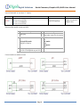
Digital Solutions Serial Character/Graphic LCD/OLED User Manual Digole Serial:UART/I2C/SPI Character/Graphic LCD/OLED Display Module User Manual This manual will describe most common futures for our Serial LCD/OLED displays and modules, each particular products may have different looks, size and material, but all interface to your master circuits and control commands are same, that means you can switch Digole Serial display in your application without any modification of you master circuit and software. Our Serial display products are list in figure-1, you can purchase them with lowest price at: http://www.digole.com/index.php?categoryID=153 What benefits you if using these products in you electronic projects? Save lots of the I/O resources: these products only need 1 to 3 I/O pins from your master controller that depends on the communication type you want. Easy to use: the commands sending to products are easy to remember and understand. On Graphic serial products: Save huge memory space to store font and start screen on graphic display: in graphic product, there are 7 preloaded fonts ready for your application, and also have 16KB memory space for your user fonts, once you uploaded the start screen or user fonts, it will stored in products. Using user fonts function, you can display any graphs or characters in any language These products already integrated graphic functions such as: draw line/rectangle/circle/image, send few bytes of instruction to products, it will do it for you, that also save your lots of code space You can display contents in 4 different directions: 0º, 90º, 180º, 270º(clockwise) on same screen, the product will map the coordinate accordingly. FEATURES: Communication mode: UART/I2C/SPI, detect your setting automatically Receiving buffer: 64/256 bytes Work with all microcontroller and microprocessor Communication signal can work on 3.3V and 5.0V TTL Default setting: UART baud 9600bps, I2C 0x27 address Page 1 Low power consumption: less than 4mA (for adapter only, completed module may higher depends on the backlight power consumption) Simple command sets, easy to remember Simple graphic engine integrated (Graphic Products) 7 preloaded fonts, font’s data structure full compatible with U8Glib(Graphic Products) UART baud (bps): 300, 1200, 2400, 4800, 9600, 14400, 19200, 28800, 38400, 57600, 115200 Digital Solutions Serial Character/Graphic LCD/OLED User Manual Figure-1 Page 2 Digital Solutions Serial Character/Graphic LCD/OLED User Manual What are adapters used for? Character adapters can work with most 1602,1604,2002,2004 and 4002 character LCDs. The Universal Graphic adapter work with 128 x 64 dots LCD, which LCD controller is ST7920 or KS0108 or ST7565. We didn’t sell adapters with a LCD due to you might already have LCDs or can easy to get one at low price from somewhere, so this way gives you more flexible options on your project. How to set up the communication mode? There are 3 different communication modes on all products: UART, I2C and SPI, what you need is just use solder to short the I2C/SPI jumper on adapter and make it works at I2C or SPI, if both jumpers are open, it works at UART, you can find a similar jumper like this: on board. Protocols: UART : 8-N-1, 8bits, No parity bit, 1 stop bit. I2C: Slave Mode, 7-bit address, default address is Hex:27, change able. This mode may give you a headache due to more signal options in I2C, but we make it works as standard, you just need setup your I2C on master controller as Standard Master Mode. SPI: 8-bits, MSB first, data on raise edge of SCK sampled; this is Standard setting on SPI too. Character/Graphic Display Shared Command: (B-one byte, B…-Bytes) Command Description Arduino lib function CL CLear screen and set the display position to first Column and first Row (x=0.y=0), for graphic LCD, it also set the font to default and turn off the cursor. CSB set CurSor on/off BLB Set Back Light ON/OFF, B=0 or 1, 0 off, 1 on DCB SBB… SI2CAB Display Config on/off, the factory default set is on, so, when the module is powered up, it will display current communication mode on LCD, after you design finished, you can turn it off Set UART Baud, B are ASCII characters, the available values are: “300”, “1200”, “2400”,”4800”, “9600”, “14400”, “19200”, “28800”, “38400”, “57600”,”115200” Set I2C Address,the default address is 0x27, the adapter will store the new address in memory Page 3 clearScreen(); enableCursor(); disableCursor(); backLightOn(); backLightOff(); note The module will not execute this command until other command received. Nor available on Character Adapter V1 displayConfig(0); displayConfig(1); Set BAUD when initial the class When adapter power up or reset, always start with 9600 Baud setI2CAddress(0x34); Change address to 0x34 Digital Solutions Serial Character/Graphic LCD/OLED User Manual STCRBBB BBB Set Text Columns and Rows, this command will config your LCD if other than 1602 and the chip is other than KS0066U/F / HD44780 setLCDColRow(20,4); The last 4 B should be“\x80\xC0\x94\xD4” TPBB set Text Position for following display setPrintPos(6,1); This will affect the following “TT” command display TexT string, the text will wraped in next row if the current row fulled, the Text Postion will be changed to the last char displyed, this command ended by 0x00 or 0x0D received print(string); print(int); print(char); print(float); print(double); drawStr(x,y,string); The print function in Arduino, also can print other data and format the out put. TTB… MCDB MDTB Manual CommanD: send command B to display bypass the adapter Manual DaTa: send data B to display bypass the adapter directCommand(0xaf); directData(0x88); Use it if you want to control the display directly Same as above Graph Display Command: (B-one byte, B…-Bytes) Command DMB DIMBBBB B… Description Set the Display Mode for on coming command, the available values for B are: “!””~” not, “|” or, “^” xor, “&” and, this means the next drawing pixel will logic operation with pixel already on screen. Display Image, 1st B is x postion, 2nd is y, 3rd B is image width, 4th is height, then following data. Each byte present 8 pixels, if the image width not divide 8, the last byte of a row only contain few pixels, eg. For width of 9 to 16, you need 2 bytes for a row SDB Send graphic fuction Direction, the value of B is 0 to 3, represent0 to 270 degree respectively. CTB Set display ConTrast, only for some models Arduino lib function setMode(‘!’); Like the Bitwise Operator in C drawBitmap(x,y,width,h igh,*data); setRotation(0); undoRotation(); setRot90(); setRot180(); setRot270(); setContrast(30); FRBBBB Draw a Filled Rectangle, 4 B are: X,Y(left top), X,Y (right bottom) drawBox(x,y,width,heig ht); DRBBBB Draw a Rectangle, 4 B are: X,Y(left top), X,Y (right bottom) drawFrame(x,y,width,h eight); CCBBBB Draw a CirCle, 4 B are: X,Y, radius, filled or not DPBBB Draw a Pixel, 3 B are: x,y and color Page 4 note drawCircle(x,y,r,f); drawDisc(x,y,r); drawPixel(x,y,color); The setRotation(); will accept 0 to 3 represent0 to 270 degree respectively In order to compatible with u8g, drawBox() in Arduino use width and height drawFrame () in Arduino use width and height f=1 means filled circel Digital Solutions Serial Character/Graphic LCD/OLED User Manual LNBBBB Draw a Line from (x,y) to (x1,y1), 4 B are: x,y,x1,y1 drawLine(x,y,x1,y1); drawHLine(x,y,width); drawVLine(x,y,height); LTBB Draw a Line from Tast position to (x,y), 2 B are:x,y drawLineTo(x,y); drawHLine()horizontal line drawVLine()veritcal line TRT Move text cursor to next line(call Text ReTurn) nextTextLine(); The y pixels moved depending on the font size current using SFB Set Font, follow by the font number, preloaded font number is: 6,10,18,51,120,123,0(default), user font number is 200,201,202,203 maps to 4 user font memory sections, you can combine adjacent sections together is the font size >4kb(each section has 4kb in size) setFont(0); We already map preloaded font to 0 to 5 in arduino lib SCB Set Color for following drawing setColor(1); 0 and 1 for black white screen MABBBBB B ETB ETOBB ETPBB SSSBBB… SUFBBBB … DSSB DOUTB SLPB Move rectangle Area on screen to another place, the 6 B are represent: (x,y)(left- top),(w,h)(width-height), (xoffset,yoffset). Enhanced set the current Text position Back to last char, this function will allow you display multiple chars at same position. Enhanced set Text position Offset, the 2 B are xoffset then yoffset, it will adjust the text position in pixels Enhanced set Text Position as pixels on screen, the 2 B are x, y coordinate on screen Set Start Screen, 1st B is the lower byte of data length, 2nd B is the higher byte of data length, following by data Set User Font, 1st B is section of memory you want to upload, 2nd B is the lower byte of data length, 3rd B is the higher byte of data length, following by data Display Start Screen stored in memory, also set up Automatic start screen display or not on next power up Send a Byte to output head on board, the current driving ability for each pin is: 25mA (Sink/Source) Set Line Pattern when drawing line, only for new version firmware later than Jan. 2013. eg. B=0xAA is dot line, B=0xFA is dash line Page 5 moveArea(x,y,w,h,xoffse t,yoffset); setTextPosBack(); setTextPosOffset(xoffset , yoffset); setTextPosAbs(x,y); uploadStartScreen(102 4, *data); The length of data should be: screen Width*High/8, eg. For 128x64 LCD, the length is 1024 uploadUserFont(1,1434, *data); displayStartScreen(1 or 0) digitalOutput(0x1F); setLinePattern(pattern) ; The output head are vary from adapters Old version not support this fucntion Digital Solutions Serial Character/Graphic LCD/OLED User Manual Special Command: (B-one byte, B…-Bytes) Command SLCDB Description Only for multi-chip driver adapter: B=0 or ‘0’ for ST7920 B=1 or ‘1’ for KS0108 B=2 or ‘2’ for ST7565 Arduino lib function setLCDChip(chip); Pinout of this module connect to MCU: PIN 1 Description PIN GND (0V) 3 I2C and SPI mode: SCK/SCL: Clock in 5 VCC: power supply 1.8V to 5.5V depends on you LCD Description 2 SS: SPI mode only chip select control in, low active 4 UART mode: RX I2C mode: SDA SPI mode: SDI Connect with your master circuit: Page 6 note For Universal Graphic Serial LCD Adapter only