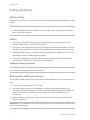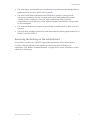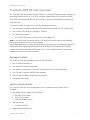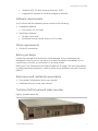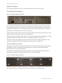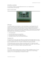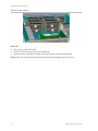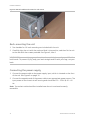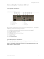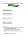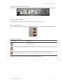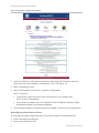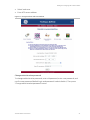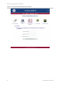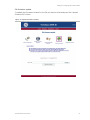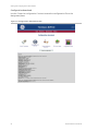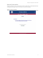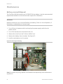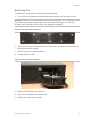
1
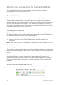
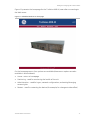
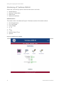
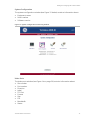
GE
Security
TruVision NVR 40 User Manual
P/N 1069162 • REV 1.0 • 13OCT09
Copyright
© 2009 GE Security, Inc.
This document may not be copied in whole or in part or otherwise reproduced without prior
written consent from GE Security, Inc., except where specifically permitted under U.S. and
international copyright law.
Disclaimer
The information in this document is subject to change without notice. GE Security, Inc.
(“GE Security”) assumes no responsibility for inaccuracies or omissions and specifically
disclaims any liabilities, losses, or risks, personal or otherwise, incurred as a consequence,
directly or indirectly, of the use or application of any of the contents of this document. For
the latest documentation, contact your local supplier or visit us online at
www.gesecurity.com.
This publication may contain examples of screen captures and reports used in daily
operations. Examples may include fictitious names of individuals and companies. Any
similarity to names and addresses of actual businesses or persons is entirely coincidental.
Trademarks and patents
GE and the GE monogram are registered trademarks of General Electric Company. The
TruVision NVR 40 name and logo are trademarks of GE Security.
Other trade names used in this document may be trademarks or registered trademarks of
the manufacturers or vendors of the respective products.
Intended use
FCC compliance
Use this product only for the purpose it was designed for; refer to the data sheet and user
documentation for details. For the latest product information, contact your local supplier or
visit us online at www.gesecurity.com.
This equipment has been tested and found to comply with the limits for a Class A digital
device, pursuant to part 15 of the FCC Rules. These limits are designed to provide
reasonable protection against harmful interference when the equipment is operated in a
commercial environment. This equipment generates, uses, and can radiate radio frequency
energy and, if not installed and used in accordance with the instruction manual, may cause
harmful interference to radio communications.
You are cautioned that any changes or modifications not expressly approved by the party
responsible for compliance could void the user's authority to operate the equipment.
Certification and compliance
Regulatory
European Union directives
TruVision NVR 40 complies with following regulations:
-
UL60950, EN60950
-
CFR47 Part15B class A, EN55022 class A, CISPR class A
-
EN50130-4
2002/96/EC (WEEE directive): Products marked with this symbol cannot be disposed of as
unsorted municipal waste in the European Union. For proper recycling, return this product
to your local supplier upon the purchase of equivalent new equipment, or dispose of it at
designated collection points. For more information see: www.recyclethis.info.
2004/108/EC (EMC directive): Non-European manufacturers must designate an authorized
representative in the Community.
2006/66/EC (battery directive): This product contains a battery that cannot be disposed of
as unsorted municipal waste in the European Union. See the product documentation for
specific battery information. The battery is marked with this symbol, which may include
lettering to indicate cadmium (Cd), lead (Pb), or mercury (Hg). For proper recycling, return the
battery to your supplier or to a designated collection point. For more information see:
www.recyclethis.info.
Contact information
For contact information see our Web site: www.gesecurity.com.
For contact information see our Web site: www.gesecurity.eu.
Content
Preface 3
Safety guidelines 4
Safe handling 4
Safety 4
Rack system safety precautions 4
Removing the battery on the motherboard 5
TruVision NVR 40 unit overview 6
Package content 6
System requirements 6
Software requirements 7
Other requirements 7
Before you begin 7
References and related documentation 7
TruVision NVR 40 network video recorder 7
Interface module 9
Storage 9
Hardware installation 11
Packing contents 11
Installation procedure 11
Rack-mounting the unit 12
Connecting the power supply 12
Connecting the TruVision NVR 40 13
Front panel connectors 13
Interface module connectors 13
Basic setup 14
Front panel LEDs 15
Starting and configuring the TruVision NVR 40 16
Turn on the unit 16
Installing on a network 16
Access the embedded web server 16
Monitoring of TruVision NVR 40 18
Access and configure TruVision NVR 40 21
Restart the TruVision NVR 40 27
Maintenance 28
Battery removal/disposal 28
Replacing fans 29
TruVision NVR 40 User Manual
i
Glossary 30
Contacting technical support 31
Online resources 31
Technical specifications 33
Dimensions 33
Weight 33
AC power module (1 x 300W PSU) 33
Standards and regulations 34
International standards 34
Potential for radio frequency interference 34
European regulations 34
ESD precautions 35
Safety compliance 35
EMC compliance 35
AC power cords 35
ii
TruVision NVR 40 User Manual
Preface
What is in this guide
This manual contains specific procedures for the initial hardware installation, and
procedures for performing the basic system configuration of your TruVision NVR 40
unit.
Audience
Setting up and maintaining a network requires the knowledge and expertise of
people with a variety of skills. In many cases, the people responsible for installing
hardware and wiring are not the ones who configure the software and administer the
network; therefore, this publication provides information specific to installing the
hardware and performing a basic system configuration. To use this publication, you
should be familiar with electronic circuitry and wiring practices, and basic network
configuration, and preferably have experience as an electronic or electromechanical
technician.
Related documentation
•
TruVision NVR 40 quick start guide
•
VOS 4.2.1 IP camera integration user manual
•
CCS 4.2.1 user manual or GE-NAV 3.0 user manual
TruVision NVR 40 User Manual
3
Safety guidelines
Safety guidelines
Safe handling
Permanently unplug the unit if you think that it has become damaged and before you
move it.
WARNING:
•
A fully assembled TruVision NVR 40 unit can weigh up to 18 kg (40 lb.). Be careful
when lifting it by yourself.
Safety
•
The TruVision NVR 40 unit must only be operated from a power supply input
voltage range of 100 to 240 VAC, 50 to 60 Hz.
•
The plug on the power supply cord is used as the main disconnect device. Ensure
that the socket outlets are located near the equipment and are easily accessible.
•
A safe electrical earth connection must be provided to the power cord. Check the
grounding of the unit before applying power.
•
Provide a suitable power source with electrical overload protection to meet the
requirements laid down in the technical specification.
Equipment handling precautions
Caution: The RJ45 sockets are for Ethernet connection only and must not be
connected to a telecommunications network.
Rack system safety precautions
The following safety requirements must be considered when the unit is mounted in a
rack.
•
The unit must be mounted in a 19” rack.
•
The rack construction must be capable of supporting the total weight of the
installed unit(s) and the design should incorporate stabilizing features suitable to
prevent the rack from tipping or being pushed over during installation or in
normal use.
•
When loading a rack with the units, fill the rack from the bottom up and empty
from the top down.
WARNING: To avoid danger of the rack toppling over, do not slide more than one unit
out of the rack at a time.
4
TruVision NVR 40 User Manual
Safety guidelines
•
The rack design should take into consideration the maximum operating ambient
temperature for the unit, which is 40°C (104°F).
•
The rack should have a safe electrical distribution system. It must provide
overcurrent protection for the unit and must not be overloaded by the total
number of units installed in the rack. When addressing these concerns
consideration should be given to the electrical power consumption rating shown
on the nameplate.
•
The electrical distribution system must provide a reliable earth for each unit and
the rack.
•
The rack when configured with the units must meet the safety requirements of UL
60950-1 and IEC 60950-1.
Removing the battery on the motherboard
This product contains one CR2032-type single-use battery. When replacing the
TruVision NVR 40, dispose of the battery as required by local ordinances or
regulations. See “Battery removal/disposal” on page 28, for more information on the
removal of the battery.
TruVision NVR 40 User Manual
5
TruVision NVR 40 unit overview
TruVision NVR 40 unit overview
The TruVision NVR 40 (model number: TVN-40) is a network video recorder, capable of
recording video from up to 12 or 24 IP cameras (depending on the specific model).
For a full list of supported devices, refer to the IP camera compatibility list published
by GE Security.
TruVision NVR 40 storage unit is typically equipped as follows:
•
One processor motherboard, with associated memory and one 2.5’’ system disk.
•
Two or four SATA disks for storage (1 TB each)
•
One extension module:
•
RS-422/RS-485 serial communication and digital I/O
Note: If you are using the device within a GE-NAV environment, go to the following
site to get the latest version of the software:
http://www.gesecurity.com/portal/site/GESecurity/menuitem.11620ebca5cc0a06574
efe10140041ca/?vgnextoid=d0b56e992c81e110VgnVCM100000592d7003RCRD
If you are using the VisioWave/UltraView CCS or VSC software solution, refer to the
appropriate CCS or VSC user manuals.
Package content
The TruVision NVR 40 package consists of the following:
•
One TruVision NVR 40 unit
•
One box with handles and screws
•
Two power cords (one for use in EU and the other one is North America)
•
One CD with TruVision NVR 40 user manuals
•
One CD with GE-NAV 3.0 application software
•
One quick start guide
System requirements
The TruVision NVR 40 is the storage part of an IP video security system, which
includes:
•
One Video security application software:
•
•
•
•
Storage device:
•
•
GE-NAV 3.0 (or later)
VSC 4.2.1 (or later)
SDK-based application
TruVision NVR 40
Video acquisition devices:
TruVision NVR 40 User Manual
6
TruVision NVR 40 unit overview
•
•
Ultraview UVE-101 (also know as Discovery-105E)
Supported IP cameras (IP Cameras Integration Manual)
Software requirements
The TruVision NVR 40 software system consists of the following:
•
Embedded software:
•
•
VOS version 4.2.1 (or later)
Application software:
•
•
GE-NAV 3.0 (or later)
VisioWave Security Center version 4.2.1 (or later)
Other requirements
•
Phillips M5 screwdriver
Before you begin
Inspect the package and contents for visible damage. If any components are
damaged or missing, do not use the unit; contact the supplier immediately. If you
need to return the unit, you must ship it in the original box.
Refer to the “Site Preparation and Safety Guidelines” on page 5 for more information
on safety measures necessary in order to perform any operation using the TruVision
NVR 40.
References and related documentation
•
Centralized Configuration Server user manual
•
VisioWave Security Center user manual
TruVision NVR 40 network video recorder
Figure 1: TruVision NVR 40 unit
TruVision NVR 40 User Manual
7
TruVision NVR 40 unit overview
Physical description
The TruVision NVR 40 unit is a 2U high enclosure for 19’ rack mounting.
TruVision NVR 40 front panel
Figure 2: TruVision NVR 40 front panel
The TruVision NVR 40 unit has all its connectors on the front panel. All functions are
thus accessible via the front panel. This includes all interface modules, start button,
and all the connectors. For an exhaustive list of connectors, see Figure 7 on page 13
and section “Front panel connectors” on page 13.
There are also three LEDs to monitor the status of the main functions of the unit. See
section Figure 10 on page 15 for more LED details.
The unit has one handle on each side of the front panel to facilitate operations. These
handles need to be installed. See section “Installing handles” on page 11.
These two mounting handles on each side of the unit also make it possible to rackmount the chassis. See section “Rack-mounting the unit” on page 12.
TruVision NVR 40 rear panel
The rear panel of the TruVision NVR 40 only contains the fans and has no connectors.
This design is user-friendly, because equipment is rack-mounted and therefore
difficult to reach from the rear panel.
Moreover, the cooling fans can directly pump air up through the rear panel that is
covered by protective foam and expel the air via the front panel.
Figure 3: TruVision NVR 40 rear panel
See “Replacing fans” on page 29 for more information on replacing fans.
8
TruVision NVR 40 User Manual
TruVision NVR 40 unit overview
Interface module
The interface modules provide additional low-cost, non-isolated serial
communication ports and I/Os.
Figure 4: Interface module
Serial port
The half/full duplex wiring selection is done by software, controlling both the H/F
input pin of the transceiver that internally connects Tx and Rx as well as selective
enabling for the receive and Transmit drivers. A switch enables the termination
resistor. Rx and Tx resistors are activated independently. Terminations are enabled by
default. Serial ports have been ESD protected. The differential drivers/receivers used
(MAX3089E), offers the following characteristics:
•
•
•
•
Fail safe Receiver
RS-422/RS-485 electrical compatibility
Enhanced electrostatic discharge protection
Selectable between half and full duplex operation
Transistor I/Os
The 4 general-purpose inputs are pulled up to high level and trigger when the circuit
is closed to the ground (active low). Inputs allow high level up to 48V. When an input is
high, its respective LED is OFF. The LED is ON when the input is grounded.
The 2 general outputs are open collectors (normally open). The maximum output
current is 500mA and outputs are able to switch signal of up to 48V. Led is OFF when
output is open. LED is ON when output is grounded (or closed).
Storage
The TruVision NVR 40 network video recorder provides embedded storage. The unit
contains two or four SATA disks (storage capacity 1 TB each) for a total storage
capacity of 2 or 4 TB (depending on the specific model).
TruVision NVR 40 User Manual
9
TruVision NVR 40 unit overview
Figure 5: RAID 0 mapping
Features
•
•
•
Two or four serial ATA disks
S.M.A.R.T disk drive monitoring for reliability
System status indication through LED (front panel) and alarm software
Note: Disks are configured and presented as single storage array to the user.
10
TruVision NVR 40 User Manual
Hardware installation
Hardware installation
The TruVision NVR 40 Network Video Recorder comes with all applicable parts
installed. The hardware installation procedure consists of mounting the unit in an
appropriate 19’ rack.
Package contents
The following items should be included in the package:
•
•
•
•
•
•
One TruVision NVR 40 unit
One box with handles and screws
Two power cords (one for use in EU and the other one in North America)
One CD with TruVision NVR 40 user manuals
One CD with GE-NAV 3.0 application software
One quick start guide
Installation procedure
Caution: Make sure that the unit is turned off before proceeding.
Installing handles
1. Lift the unit safely out of the packing container.
As you unpack the unit, check for signs of shipping damage (damaged box,
scratches, dents, etc.). If the unit is damaged or fails to meet specifications, notify
the VisioWave support department or your local representative immediately. Also
notify the carrier. Retain the shipping cartoon and packing material for inspection
by the carrier.
2. Ensure the power service at the site is suitable for the unit you are installing.
3. Check the packing slip to ensure that all the proper components are present.
4. Open the accessories box. There are two handles and eight screws per unit.
5. Screw the handles to the chassis. There are four screws per handle. See Figure 6,
item 2.
TruVision NVR 40 User Manual
11
Hardware installation
Figure 6: NVR 40 handles and screws for rack mount
Rack-mounting the unit
1. Two handles for 19’ rack mounting are included with the unit.
2. Carefully align the unit with the rack and slide it into position, and then fix the unit
to the rack with the screws provided. See Figure 6, item 1.
WARNING: To prevent injury, grasp the unit underneath the lower edge, and lift with
both hands. To prevent injury, keep your back straight and lift with your legs, not your
back.
Connecting the power supply
1. Connect the power cable to the power supply input, which is situated on the front
of the unit. See Figure 9 on page 15.
2. Connect the opposite end of the power cable to an appropriate power source. The
input power to the chassis is self-sensing and should be 110 ~ 230 V @ 50 ~ 60
Hz.
Note: The socket-outlet should be installed near the unit and must be easily
accessible.
12
TruVision NVR 40 User Manual
Connecting the TruVision NVR 40
Connecting the TruVision NVR 40
Front panel connectors
Figure 7: NVR 40 front panel connectors
1.
Power socket
5.
VGA
2.
Interface module
6.
LEDs
3.
Keyboard and mouse
7.
USB ports
4.
Power button
8.
Ethernet ports
All connectors are located on the front panel of the chassis (see Figure 7 above). The
NVR 40 unit contains the following connectors:
•
•
•
•
•
•
•
One keyboard connector (purple) and one mouse connector (green)
Four high-speed USB 2.0 ports
One VGA connector
Two Ethernet ports (10/100/1000 Mbps)
One On/Off button
One power plug
One interface module
Interface module connectors
The peripheral equipment can be connected either by using the front motherboard
connector or the interface I/O or serial port modules.
As far as the interface modules are concerned, pins are numbered from left to right
when facing the interface module.
TruVision NVR 40 User Manual
13
Connecting the TruVision NVR 40
Figure 8: The Interface module connector and pin position
The detailed specifications for the module’s pins are shown in Table 1.
Table 1: Module pin description
Serial + I/O 485IO-UM-1
Signal
Pin
VCC5V
14
N/C
13
GND
12
RXD1 +
11
RXD1 -
10
TXD1 +
9
TXD1 -
8
GND
7
GPI2I
6
GPI22
5
GPI23
4
GPI24
3
GPO21
2
GPO22
1
Note: For GE-NAV, only the four alarm inputs are configurable. While for VSC and
VisioWave, four alarm inputs, two outputs, and one RS-422/RS-485 are configurable.
Basic setup
To start the TruVision NVR 40 unit and connect to the network, follow this procedure:
1. Attach the power cord to the unit. See Figure 9, item 1
2. Attach the Ethernet cable to the Ethernet port. See Figure 9, item 2.
3. Press the power button on the front panel, to turn on the unit. See Figure 7.
4. The topmost LED on the front panel indicates whether AC mains power is present,
constant green indicates when the power is on. See Figure 10 on page 15.
5. You are now ready to configure the TruVision NVR 40 through its Web server
using a host computer. See Figure 11 on page 17.
14
TruVision NVR 40 User Manual
Connecting the TruVision NVR 40
Figure 9: NVR 40 basic setup connections
Front panel LEDs
There are 3 different LED indicators on the front panel of the unit.
Figure 10: Front panel LEDs
Table 2: Front panel LEDs
Icon
LED
Description
Power status
This LED indicates when the unit is turned on. Constant green
indicates power on.
Storage status/activity
This LED monitors the status of the storage in the system.
VOS (video operating
system) identification LED
This LED indicates when the embedded software (VisioWave Security
Service) has detected an abnormal condition or a failure.*
* In case of storage failure (LED is constant red), contact technical support.
TruVision NVR 40 User Manual
15
Starting and configuring the TruVision NVR 40
Starting and configuring the TruVision NVR 40
This chapter describes the start up procedure and the necessary software
configuration of the TruVision NVR 40 unit.
Turn on the unit
Turn on the unit (press the power button on the unit). See Figure 7 on page 13.
The VisioWave video operating system (VOS) and the VisioWave Security Service
software will then start up automatically. Configure the network parameters the first
time the video equipment is switched on. See “Network configuration” on page 21.
Otherwise the VisioWave Central Configuration server will not detect the unit and its
input and output video channels on the net.
Installing on a network
The TruVision NVR 40 is installed on an Ethernet network. This involves assigning it an
IP address, either manually or via an automated network service (DHCP). Depending
on your network, select one of the following procedures:
•
•
Automatic configuration using DHCP, see “Network configuration” on page 21.
Manual configuration using fixed IP address, see “Network configuration”
on page 21.
Note: The TruVision NVR 40 has the default IP address 192.168.1.2 (Mask 255.255.0.0).
DHCP is disabled by default.
Monitoring system
The monitoring system detects abnormal system operating conditions and generates
alarm outputs or messages, allowing users to take necessary actions before system
failure.
The monitoring system can detect a wide variety of internal system conditions
including temperature, voltage, fan operation, and power supply status. It can
generate several different alarm outputs, including audible signals to notify nearby
users or sending out alarm messages for remote notification. SNMP traps are also
available.
Access the embedded web server
To access the unit via a Web server, use the default fixed IP address: 192.168.1.2
16
TruVision NVR 40 User Manual
Starting and configuring the TruVision NVR 40
Figure 11 presents the homepage for the TruVision NVR 40, seen after connecting to
the Web server.
Figure 11: Embedded Web server homepage
On the homepage menu, four options are available (these menu options are also
available in other widows):
•
Home - return to homepage
•
Monitoring - used for monitoring the health of the unit
•
Administration - used for logon, network configuration, and setting/changing
access rights.
•
Restart - used for restarting the device (for example, for changes to take effect)
TruVision NVR 40 User Manual
17
Starting and configuring the TruVision NVR 40
Monitoring of TruVision NVR 40
Select the “Monitoring” option from the main menu to check:
•
•
•
•
Health Metrics
System Configuration
Video Ports
Network Interfaces
Health Metrics
The health metric window (see Figure 12 below) contains information about:
•
•
•
•
•
•
•
•
CPU Temperature
CPU Fan Speed
Core Voltage
+3.3 V
+5 V
+ 12 V
System Date & Time
Uptime
Figure 12: Health metric window
18
TruVision NVR 40 User Manual
Starting and configuring the TruVision NVR 40
System Configuration
The system configuration window (see Figure 13 below) contains information about:
•
•
•
Equipment name
Serial number
Software version
Figure 13: System configuration monitoring window
Video Ports
The video ports window (see Figure 14 on page 20) contains information about:
•
•
•
•
•
•
•
•
•
•
Slot number
Port number
Direction
Label
TCP Port
Format
Size
FPS
Bandwidth
Status
TruVision NVR 40 User Manual
19
Starting and configuring the TruVision NVR 40
Figure 14: Video ports window
Network interfaces
The network interfaces window (see Figure 15 on page 21) contains information
about:
•
•
•
•
•
•
•
•
20
Connection Type
IP/Mask
Cable Status
Rx/Tx Packets
Rx/Tx Errors
MAC Address
Default Gateway
Ethernet Configuration
TruVision NVR 40 User Manual
Starting and configuring the TruVision NVR 40
Figure 15: Network interfaces window
Access and configure TruVision NVR 40
Select the “Administration” option in the main menu to access the Administration
window. The default login is “admin” and the default password is “admin”.
Four options in the administration menu are available:
•
•
•
•
•
Network configuration
Manually set system date and time
Change administrative password
File firmware update
Configuration download
Network configuration
To set the network configuration, follow the procedure below:
1. Connect to the NVR 40 unit using a Web server. Use the default IP address
192.168.1.2 (Mask 255.255.0.0). See “Access the embedded web server”
on page 16.
TruVision NVR 40 User Manual
21
Starting and configuring the TruVision NVR 40
Figure 16: Network configuration window
2. Access the device configuration window, by selecting Administration from the
main menu and then Network Configuration icon. See Figure 16.
3. Select the Adapter name.
4. Select the mandatory options for network configuration:
DHCP or Static IP
•
To set DHCP, select the DHCP Auto Configuration of IP Address box.
DHCP is NOT set as default
•
To set static IP address, fill in the available fields: IP Address, Network Mask,
Broadcast Address, and Gateway Address.
5. Click the Apply button at the bottom of the window, to confirm the configuration.
Manually set system date and time
To manually set system date and time, enter required data in the fields below:
•
•
22
Enter new date (mm/dd/yyyy)
Enter new time (hh.mm.ss)
TruVision NVR 40 User Manual
Starting and configuring the TruVision NVR 40
•
•
Select local zone
Enter NTP server address
Figure 17: Set system date and time window
Change administrative password
To change administrative password, enter old password, enter new password, and
confirm new password (default login and password is admin/admin). Then press
“Change administrative password” button.
TruVision NVR 40 User Manual
23
Starting and configuring the TruVision NVR 40
Figure 18: Change administrative password window
24
TruVision NVR 40 User Manual
Starting and configuring the TruVision NVR 40
File firmware update
To update the firmware, browse for the file you want to load and press the “upload
firmware file” button.
Figure 19: Update firmware window
TruVision NVR 40 User Manual
25
Starting and configuring the TruVision NVR 40
Configuration download
Use the “Save the configuration” button to save the configuration file to the
designated place.
Figure 20: Configuration download window
26
TruVision NVR 40 User Manual
Starting and configuring the TruVision NVR 40
Restart the TruVision NVR 40
Select the “Restart” option from the main menu to restart the unit and reset with new
configuration settings. Use the “OK” button to confirm the restart.
Figure 21: Restart unit window
TruVision NVR 40 User Manual
27
Maintenance
Maintenance
Battery removal/disposal
The TruVision NVR 40 contains one 3V CR2032 lithium battery. Use the recommended
replacement batteries or contact technical support for information.
WARNING:
Make sure that the unit is turned off before proceeding. There is a risk of explosion, if
the battery is replaced by an incorrect type.
1. Turn off the unit's power switch and unplug the power supply cable from its
power source.
2. Turn off all accessories connected to the unit.
3. Remove the cover from the TruVision NVR 40 unit.
4. Remove the battery from its socket. See Figure 22.
5. Install a new battery into this socket.
Figure 22: Removing the battery
Note: For proper recycling, dispose of all batteries as required by local ordinances or
regulations.
28
TruVision NVR 40 User Manual
Maintenance
Replacing fans
To replace the cooling fans, follow the procedure below:
1. Turn off the unit’s power and unplug the power supply from its power source.
WARNING: Wait for 15 seconds after switching off the power. This is important as the
fans have no protective cover and the user can insert the fingers in the fans by
accident, you must wait until the fans have stopped completely.
Figure 23: Rear panel with cooling fans
2. The four fans are mounted at the rear of the chassis. Unscrew the cover bolts on
the fan you need to replace.
3. Pull out the fan you need to replace.
4. Unplug the fan’s cable.
Figure 24: Rear panel with cooling fans
5. Replace the failed fan by a new fan.
6. Plug in the fan cable and insert the fan.
7. Replace the cover of the chassis
TruVision NVR 40 User Manual
29
Glossary
Glossary
BIOS
Basic Input-Output System, computer software (firmware) controlling low-level I/O
COM
The name of a serial communication port.
DHCP
Dynamic Host Configuration protocol, a protocol for assigning IP addresses to
devices on a network
I/O
Input/Output.
IP
Internet Protocol, specifies the format of packets, also called datagrams and
addressing scheme
LAN
Local Area Network, a network spanning a small physical area and operating at
high speed
LED
Light Emitting Diode
RAID
Redundant Array of Independent Disks
SATA
Serial ATA, is a serial link, i.e. a single cable with a minimum of four wires creating a
point-to-point connection between devices.
SMART
Self-Monitoring, Analysis and Reporting Technology, an open standard for
developing disk drives and software systems that automatically monitor a disk
drive’s health and report potential problems.
SNMP
Simple Network Management Protocol, a set of protocols for managing complex
networks.
USB
Universal Serial Bus
VOS
Video Operating System, VisioWave global solution for video security.
30
TruVision NVR 40 User Manual
Contacting technical support
Contacting technical support
For help installing, operating, maintaining, and troubleshooting this product, refer to
this document and any other documentation provided. If you still have questions,
contact us during business hours (Monday through Friday, excluding holidays).
Note: Be ready at the equipment before calling.
Table 3: Technical support
North America
T:
F:
E:
Latin America
888 GE Security (888.437.3287) Toll-free in the T: +1.305.593.4301
US, Puerto Rico, and Canada.
F: +1.305.593.4300
503.885.5700 outside the toll-free area.
E: [email protected]
888.329.0332 (Tualatin tech support)
[email protected]
561.998.6232 (Boca Raton tech support)
[email protected]
[email protected]
Australia, New Zealand
Europe, Middle East, and Africa
E:
T:
+ 48 (58) 326 2240
F:
+ 48 (58) 326 2241
E:
[email protected]
[email protected]
W: At www.gesecurity.eu, select Customer
Support.
China, India, Singapore, Taiwan, Southeast Asia
E:
[email protected]
Online resources
Here are some useful links on our website www.gesecurity.com:
Online library
From the Customer Support menu, select the Resource Library link. After you register
and log on, you may search for the documentation you need. For other (non-English)
languages contact your local supplier.
Training
To view any available online training for GE Security products, select the Training
link.(Online training is not available for all products.)
TruVision NVR 40 User Manual
31
Contacting technical support
Warranty and terms information
From the Customer Support menu, select Return and Warranty Policy Statement or
Terms and Conditions Policy Statement.
Customer service and technical support
From the Customer Support menu, select Customer Service or Technical & Application.
Select the appropriate product category for the contact information or use the menu
to select a location outside the US.
32
TruVision NVR 40 User Manual
Technical specifications
Technical specifications
Dimensions
Rack unit
Millimeters Inches
Height
89
3.46
Width across mounting flange
483
19.01
Width across body of the unit
449
17.68
Depth from rack posts to maximum extremity of the unit
495
19.5
Weight
Maximum configuration
18 kg (40 lb.)
AC power module (1 x 300W PSU)
Voltage range
100 to 240 VAC Rated
Voltage range selection
Full Range PSU
Frequency
50/60 Hz
Input current
6A
Power factor correction
95%@110 V 50% load
Harmonics
Meets EN61000-3-2 class B
TruVision NVR 40 User Manual
33
Standards and regulations
Standards and regulations
International standards
The TruVision NVR 40 unit complies with the requirements of the following agencies
and standards:
•
CE to EN 60950-1
•
CB report to IEC 60950-1
•
UL 60950-1
Potential for radio frequency interference
USA Federal Communications Commission (FCC)
Note: This equipment has been tested and found to comply with the limits for a class
A digital device, pursuant to Part 15 of the FCC rules. These limits are designed to
provide reasonable protection against harmful interference when the equipment is
operated in a commercial environment. This equipment generates, uses, and can
radiate radio frequency energy and, if not installed and used in accordance with the
instruction manual, may cause harmful interference to radio communications.
Operation of this equipment in a residential area is likely to cause harmful
interference in which case the user will be required to correct the interference at own
expense.
Properly shielded and grounded cables and connectors must be used in order to
meet FCC emission limits. The supplier is not responsible for any radio or television
interference caused by using other than recommended cables and connectors or by
unauthorized changes or modifications to this equipment. Unauthorized changes or
modifications could void the user’s authority to operate the equipment.
This device complies with Part 15 of the FCC Rules. Operation is subject to the
following two conditions: (1) this device may not cause harmful interference, and (2)
this device must accept any interference received, including interference that may
cause undesired operation.
European regulations
This equipment complies with European Regulations EN 55022 Class A: Limits and
Methods of Measurement of Radio Disturbance Characteristics of Information
Technology Equipment and EN50082-1: Generic Immunity.
34
TruVision NVR 40 User Manual
Standards and regulations
ESD precautions
Caution: It is recommended that you fit and check a suitable anti-static wrist or ankle
strap and observe all conventional ESD precautions when handling TruVision NVR 40
plug-in modules and components.
Safety compliance
System product type approval
UL, CE
Safety compliance
UL 60950
EN 60950
EMC compliance
Conducted emissions limit levels CFR47 Part 15B Class A
EN55022 Class A
CISPR Class A
Radiated emissions limit levels
CFR47 Part 15B Class A
EN55022 Class A
CISPR Class A
Harmonics and flicker
EN61000-3-2/3
Immunity limit levels
EN55024
Note: The cable must not have a connection to a common ground/earth point.
AC power cords
United States
Must be NRTL LISTED (National Recognized Test Laboratory, e.g. UL)
Cord type
SV or SVT, 18 AWG minimum, 3 conductor, 4.5 m
maximum length.
Plug
NEMA 5-15P grounding-type attachment plug
rated 120 V 10 A;
or
IEC 320 C14, 250 V, 10 A.
Socket
IEC 320, C-13, 250 V, 10 A.
TruVision NVR 40 User Manual
35
Standards and regulations
Europe & others
General requirements:
Cord type
Harmonized, H05-VVF-3G1.0
Socket
IEC 320, C-13, 250 V, 10 A.
Caution: The Plug and the complete power cord assembly must meet the standards
appropriate to the country, and must have safety approvals acceptable in that
country.
36
TruVision NVR 40 User Manual