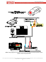
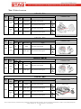
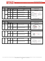
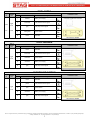
1
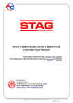
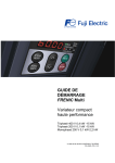
Installation manual
Fuel Pressure Emulator
FPE-A
„04-141.00.00.1
09.02.2015”
AC S.A. All rights reserved. Any unauthorized copying, reproduction, publishing, dissemination, disclosing or other use of information presented herein, in whole or as part, particularly photographs,
drawings, trademarks, etc., may lead to prosecution or civil proceedings.
Contents:
1. Technical data........................................................................................................ 2
2. Applications............................................................................................................ 2
3. Operating principle ................................................................................................. 2
4. Wiring diagram and installation remarks ................................................................ 2
5. Emulator start......................................................................................................... 8
6. Notes ..................................................................................................................... 8
7. Warranty Document ............................................................................................... 9
1. Technical data
12V ±25%
-40°C ÷ +70°C
IP40
Supply voltage:
Operating temperature:
Protection Class:
2. Applications
The FPE-A fuel pressure emulator equipped with autoadaptation functionality is designed for
use in a wide range of vehicle models, in which errors related to the pressure controller circuit in
the fuel rail or high/low rail pressure occur during operation of the engine fuelled by LPG/CNG.
It is compatible with the following vehicle models:
Volvo: S40, S60, S60R, S80, XC70, XC90
Opel: Astra , Insignia
Chevrolet: Captiva
Exact versions of supported models are listed in the following sections.
3. Operating principle
When the engine is fueled by LPG/CNG, there is no supply of petrol from the rail, so the rail
pressure is not changing as expected by the petrol ECM. This is interpreted as an error in the
pressure control circuit. As a consequence, the ECM shortens the injection time pulses and/or
reports a failure that may make continuation of driving impossible. The FPE-A works with the
regulator circuit and solves the problem. After installation and the first start-up, the activated
adaptation function selects the parameters and emulation mode for a given car in an automatic
mode. The settings are stored in system non-volatile memory and can be modified only with
another adaptation cycle.
4. Wiring diagram and installation remarks
The supplied universal emulator harness should be connected in accordance with the indicated
wiring diagram and recommendations of the table with versions dedicated to specific cars. The
location of emulator installation depends on the wiring diagram for a specific version and
configuration of the fuel pressure control system.
AC S.A. All rights reserved. Any unauthorized copying, reproduction, publishing, dissemination, disclosing or other use of information presented herein, in whole or as part, particularly photographs,
drawings, trademarks, etc., may lead to prosecution or civil proceedings.
2
SCH1. Wiring diagram for connection of the FPE-A fuel pressure emulator with the vehicle
system, close to the petrol ECM.
AC S.A. All rights reserved. Any unauthorized copying, reproduction, publishing, dissemination, disclosing or other use of information presented herein, in whole or as part, particularly photographs,
drawings, trademarks, etc., may lead to prosecution or civil proceedings.
3
SCH2. Wiring diagram for connection of the FPE-A fuel pressure emulator with the vehicle
system, close to the fuel pump controller.
AC S.A. All rights reserved. Any unauthorized copying, reproduction, publishing, dissemination, disclosing or other use of information presented herein, in whole or as part, particularly photographs,
drawings, trademarks, etc., may lead to prosecution or civil proceedings.
4
Tab. 1 Table of versions
VOLVO S40
Engi
ne
Year of
manufac
ture
Petrol ECM harness
Installation notes
Conne
ctor
Pin
No.
Wire colour
B
20
white-black
Fuel pump control signal
A
91
white-blue
Fuel pressure sensor signal
B
21
white-black
Fuel pump control signal
A
89
white-blue
Fuel pressure sensor signal
Signal
ECM location
2005
2.5T
2006
÷
2011
Wiring diagram: SCH 1.
VOLVO S60
Engi
ne
Year of
manufac
ture
Petrol ECM harness
Installation notes
Conne
ctor
Pin
No.
Wire colour
B
47
yellow
A
2
green-grey
Signal
ECM location
2.5T
Fuel pump control signal
2004
÷
2009
Fuel pressure sensor signal
Wiring diagram: SCH 1.
VOLVO S60 R
Engi
ne
Year of
manufac
ture
Petrol ECM harness
Installation notes
Conne
ctor
Pin
No.
Wire colour
B
47
yellow
A
2
green-grey
Signal
ECM location
2.5T
Fuel pump control signal
2004
÷
2009
Fuel pressure sensor signal
Wiring diagram: SCH 1.
VOLVO S80
Engi
ne
Year of
manufac
ture
2004
÷
2006
Petrol ECM harness
Installation notes
Conne
ctor
Pin
No.
Wire colour
B
47
yellow
A
2
green-grey
B
21
yellow-orange
A
89
blue-brown
Signal
Fuel pump control signal
ECM location
Fuel pressure sensor signal
2.5T
2007
÷
2011
Fuel pump control signal
Fuel pressure sensor signal
Wiring diagram: SCH 1.
AC S.A. All rights reserved. Any unauthorized copying, reproduction, publishing, dissemination, disclosing or other use of information presented herein, in whole or as part, particularly photographs,
drawings, trademarks, etc., may lead to prosecution or civil proceedings.
5
VOLVO XC70
Engi
ne
Year of
manufac
ture
2004
÷
2007
Petrol ECM harness
Installation notes
Conne
ctor
Pin
No.
Wire colour
B
47
yellow
A
2
green-grey
B
21
yellow-orange
A
89
blue-brown
Signal
Fuel pump control signal
ECM location
Fuel pressure sensor signal
2.5T
2007
÷
2011
Fuel pump control signal
Fuel pressure sensor signal
Wiring diagram: SCH 1.
VOLVO XC90
Engi
ne
Year of
manufac
ture
Petrol ECM harness
Installation notes
Conne
ctor
Pin
No.
Wire colour
B
47
yellow
A
2
green-grey
Signal
ECM location
2.5T
Fuel pump control signal
2004
÷
2011
Fuel pressure sensor signal
Wiring diagram: SCH 1.
ECM location
3.3
B
21
yellow
A
71
green-grey
Fuel pump control signal
2007
÷
2011
Fuel pressure sensor signal
Wiring diagram: SCH 1.
4.4
B
20
yellow
A
71
green-grey
Fuel pump control signal
ECM location
2007
÷
2011
Fuel pressure sensor signal
Wiring diagram: SCH 1.
AC S.A. All rights reserved. Any unauthorized copying, reproduction, publishing, dissemination, disclosing or other use of information presented herein, in whole or as part, particularly photographs,
drawings, trademarks, etc., may lead to prosecution or civil proceedings.
6
OPEL ASTRA
Engi
ne
1.4T
1.6
Year of
manufac
ture
2009
÷
2014
2009
Fuel pump controller harness
Pin No.
Wire colour
1
red-blue
10
blue-white
13
grey
21
violet-green
25
black
Installation notes
Signal
Connector of fuel pump controller
Battery +12V supply
Fuel pressure sensor signal
Fuel pump control signal
Ignition switch
GROUND
Wiring diagram: SCH 2.
OPEL INSIGNIA
Engi
ne
2.8T
Year of
manufac
ture
2009
÷
2013
Fuel pump controller harness
Pin No.
Wire colour
1
black
10
blue-white
Fuel pressure sensor signal
15
violet-blue
Ignition switch
32
red-white
Battery +12V supply
47
grey
Installation notes
Signal
Connector of fuel pump controller
GROUND
Fuel pump control signal
Wiring diagram: SCH 2.
CHEVROLET CAPTIVA
Engi
ne
2.4
Year of
manufac
ture
2006
÷
2010
Fuel pump controller harness
Pin No.
Wire colour
1
black
GROUND
10
yellow
Fuel pressure sensor signal
15
pink
32
red-white
47
grey
Installation notes
Signal
Connector of fuel pump controller
Ignition switch
Battery +12V supply
Fuel pump control signal
Wiring diagram: SCH 2.
AC S.A. All rights reserved. Any unauthorized copying, reproduction, publishing, dissemination, disclosing or other use of information presented herein, in whole or as part, particularly photographs,
drawings, trademarks, etc., may lead to prosecution or civil proceedings.
7
5. Emulator start
Following the installation of FPE-A, adaptation must be performed.
1. Start the engine on petrol and keep it on idle until the rated operating temperature is
reached.
2. Make sure that the LPG/CNG change-over switch is set in the petrol fuel mode and stop
the engine.
3. Turn off the ignition switch.
4. Disconnect the FPE-A from the harness female connector, wait min. 5s and reconnect
the emulator. When the rubber cover on the connector is pulled off, an lit internal red LED
should be seen.
5. Turn on and turn off the ignition switch three times within 30s after emulator connection
to the harness socket. The internal red LED should start flashes slowly.
6. Start the engine. The internal red LED should start flashes fast.
7. Leave the car on idle for about 2 minutes until the internal red LED light stops flashing
and lights up permanently.
8. Switch car to gas and wait until the LED light will shut down. This means that the
adaptation process is completed.
When the adaptation is completed, the emulator is ready to work on LPG/CNG mode. If the
adaptation process is interrupted, the whole procedure must be restarted.
6. Notes
Correct operation of the emulator requires the following conditions to be met:
The emulator should be connected in accordance with the wiring diagram and
recommendations of the table with unit versions.
The emulator has been installed in the correct location (SCH1 for the ECM area and
SCH2 for the fuel pump controller area).
The adaptation process has been completed successfully.
AC S.A. All rights reserved. Any unauthorized copying, reproduction, publishing, dissemination, disclosing or other use of information presented herein, in whole or as part, particularly photographs,
drawings, trademarks, etc., may lead to prosecution or civil proceedings.
8
7. Warranty Document
Quality warranty terms and conditions:
AC S.A. with its registered seat in Bialystok ensures good quality, correct operation and efficient
functioning of the purchased equipment for which this Warranty Document was issued on the
territory of the country the purchase was made in. The warranty is given on the following terms
and conditions:
1. WARRANTY COVERAGE
1) this warranty concerns proper functioning of the equipment and is valid on the territory of the
country the purchase was made in,
2) the warrantor is only responsible for defects due to reasons within the sold equipment and for
consequential damages to this equipment,
3) the warranty does not cover
a) normal operating wear of the equipment,
b) equipment which has been modified, repaired or infringed in any way by the Customer or any
third persons.
2. WARRANTY TERMS AND CONDITIONS AND PROCEDURE
1) the basis for exercising the warranty rights is to submit the properly filled up original Warranty
Document;
2) to exercise the warranty rights, you should immediately report any noticed defect to the local
Distributor of AC S.A. (for the valid list of Distributors, visit the website at www.ac.com.pl),
delivering the defective equipment with the Warranty Document and a copy of the purchase
receipt. The Distributor is responsible for delivery of defective goods to the Quality Control
Department of AC S.A.
3. WARRANTY PERFORMANCE TIME
1) the manufacturing defects of the equipment should be removed and inoperative components
should be removed repaired or replaced within 14 days of equipment delivery to AC S.A.;
2) in non-standard cases, the repair time may be extended.
4. WARRANTY PERIOD
1) the warranty period is 24 months from the date of sale;
2) the warranty expires in the event when the Customer fails to observe provisions of the Warranty
Document, in particular in case of:
a) misuse of the equipment,
b) mechanical damages,
c) any unauthorised alterations to the equipment,
d) failure to observe the instructions of correct operation, in particular those in the Operating
Manual,
e) other damages through the fault of the user.
5. FINAL PROVISIONS
This warranty for sold goods does not exclude, restrict or suspend the Purchaser’s rights arising
from product’s inconsistency with the agreement.
Any disputes under this warranty shall be settled by the court having jurisdiction over the seat of
AC S.A.
..................................................
date of sale
..................................................
stamp and signature
of the Seller
AC S.A. All rights reserved. Any unauthorized copying, reproduction, publishing, dissemination, disclosing or other use of information presented herein, in whole or as part, particularly photographs,
drawings, trademarks, etc., may lead to prosecution or civil proceedings.
9