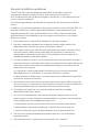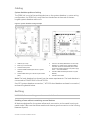
1
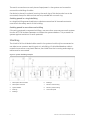
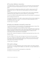
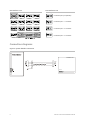
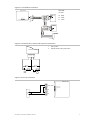
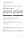
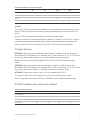
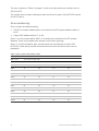
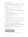
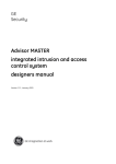
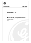
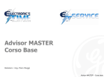
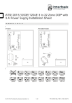
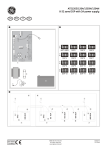
GE
Security
ATS125x 4-Door DGP Installation
Manual
P/N 1065711 • REV 1.0 • ISS 28APR09
Copyright
© 2009 GE Security, Inc.
This document may not be copied in whole or in part or otherwise reproduced without prior
written consent from GE Security, Inc., except where specifically permitted under US and
international copyright law.
Disclaimer
The information in this document is subject to change without notice. GE Security, Inc.
(“GE Security”) assumes no responsibility for inaccuracies or omissions and specifically disclaims
any liabilities, losses, or risks, personal or otherwise, incurred as a consequence, directly or
indirectly, of the use or application of any of the contents of this document. For the latest
documentation, contact your local supplier or visit us online at www.gesecurity.com.
This publication may contain examples of screen captures and reports used in daily operations.
Examples may include fictitious names of individuals and companies. Any similarity to names
and addresses of actual businesses or persons is entirely coincidental.
Trademarks and patents
GE and the GE monogram are trademarks of General Electric Company. The ATS Advisor Master
name and logo are trademarks of GE Security.
Other trade names used in this document may be trademarks or registered trademarks of the
manufacturers or vendors of the respective products.
Intended use
Use this product only for the purpose it was designed for; refer to the data sheet and user
documentation for details. For the latest product information, contact your local supplier or visit
us online at www.gesecurity.com.
Certification and compliance
European directives
1999/5/EC (R&TTE directive): Hereby, GE Security declares that this device is in compliance with
the essential requirements and other relevant provisions of Directive 1999/5/EC.
2002/96/EC (WEEE directive): Products marked with this symbol cannot be disposed of as
unsorted municipal waste in the European Union. For proper recycling, return this product to
your local supplier upon the purchase of equivalent new equipment, or dispose of it at
designated collection points. For more information see: www.recyclethis.info.
2004/108/EC (EMC directive): Non-European manufacturers must designate an authorized
representative in the Community. Our authorized manufacturing representative is:
GE Security B.V., Kelvinstraat 7,
6003 DH Weert, The Netherlands.
Contact information
For contact information see our Web site: www.gesecurity.com.
Content
Important information ii
Installation 1
ATS125x 4-door DGP overview 1
Connections 2
Battery replacement 3
Important notes on mounting 3
LEDs 3
General installation guidelines 4
Cabling 5
Earthing 5
Shielding 6
ATS system databus connection 7
ATS125x local databus and earth connection 7
DIP switch settings 7
Connection diagrams 8
Zones, RASs and outputs 10
Numbering 10
Outputs devices 11
ATS125x default zone and relay settings 11
Door numbering 12
Power-up procedure 13
Setup procedure 13
How to access the ATS125x programming menu 13
ATS125x programming menus 14
Initialise the database 14
Poll connected RASs 15
Troubleshooting 16
ATS system data bus indicator LED’s 16
4-door DGP local data bus indicator LEDs 16
Programming map 17
Specifications 19
ATS125x 4-Door DGP Installation Manual
i
Important information
This manual provides information for the following 4-door access control data
gathering panels (DGPs): ATS1251, ATS1252, ATS1253, and ATS1254. When referring
to the 4-door DGP, this can be read as any model of the ATS125x, unless specifically
stated otherwise.
Table 1: List of existing 4-door DGP models
Model
Auxiliary power
Locks power
Housing
Dimensions
ATS1251
12 V
12 V
ATS1642 big enclosure
480 x 464 x 160 mm
ATS1252
12 V
24 V*
ATS1642 big enclosure
480 x 464 x 160 mm
ATS1253
12 V
12 V
ATS1640 small enclosure
445 x 315 x 90 mm
ATS1254
12 V
24 V*
ATS1640 small enclosure
445 x 315 x 90 mm
* For 24 VDC models, always use two batteries in series.
ii
ATS125x 4-Door DGP Installation Manual
Installation
ATS125x 4-door DGP overview
The figure below shows the 4-door DGP layout.
Figure 1: ATS125x layout
ADDRESS
J1
~
IC13 RAM/IUM
CON1
~
2
LK1
PTC1
+
+
MODE
1
LK2
PTC2
CON2
3
-
IC6 EPROM
+
+ S+
S-
4
LK10
KILL
+
K1
-
RST
+
-
CON3
NO
CON4
ATS125x
K2
COM
NC
F2
F3
F4
F5
F6
F7
5
6
7
8
9
10
11
K3
NC
Tx
Rx
Tx1
LK11
Rx1
NO
COM
NO
F1
TST3
K4
CON5
LK6
LK3 LK4
LK7
NC
TERM1
TST1 TST2
NO
12
CON14
CON13
INPUT EXPANDER
OUTPUT EXPANDER
LK8
COM
CON6
TERM2
TERM3
13
CON7
14
CON8
16
15
CON9
CON10
CON11
TxD
RxD
CTS
RTS
COM
4
5
C
6
7
C
8
D-
C
0V
3
D+
2
D-
C
12V
1
0V
C
D+
0V D+ D- T
12V
NC
N
L
17
1.
DIP switches (see “DIP switch settings” on page 7)
10. Lock power 2 fuse F6
2.
RAM or IUM (optional)
11. Siren / switch fuse F7
3.
EPROM (factory fitted)
4.
KILL jumper: Factory default ATS125x when
shorted
12. TERM 1: Use this link to terminate the system
databus
13. TERM 2: Use this link to terminate the local
databus, connection 1 on terminal CON9
5.
Battery fuse F1
6.
Auxiliary power fuse F2
14. TERM 3: Use this link to terminate the local
databus, connection 2 on terminal CON10
7.
Databus 1 fuse F3
15. CON14 Input expander connector
8.
Databus 2 fuse F4
9.
Lock power 1 fuse F5
ATS125x 4-Door DGP Installation Manual
16. CON15 Output expander connecter
17. Mains terminal
1
Connections
Table 2: ATS125x connections
Terminal block
Wire
Description
CON1
∼, ∼
Mains power connection
System earth (see details on page 5).
+, −
2 x 12 V batteries, 7.2 Ah (24 V version) *
1 x 12 V battery, 7.2 Ah (12 V version)
+, −
Aux. power
+, −
Aux. power
S+, S− **
External siren output
+, −
Lock 1 power
+, −
Lock 2 power
NO, COM, NC
Door 1 relay
NO, COM, NC
Door 2 relay
NO, COM, NC
Door 3 relay
NO, COM, NC
Door 4 relay
0V, D+, D−
System databus and panel tamper wiring (see page 7 for details).
T, C
Tamper switch
1, 2, 3, 4
Zone 1-4 inputs
C
Common
5, 6, 7, 8
Zone 5-8 inputs
C
Common
CON9
12V, 0V, D+, D−
Local databus to connect RASs and DGPs (see page 7 for details).
CON10
12V, 0V, D+, D−
Local databus to connect RASs and DGPs (see page 7 for details).
CON2
CON3
CON4
CON5
CON6
CON7
CON8
* For 24 VDC models, always use two batteries in series.
** External siren output is a supervised output. Typical EOL resistor is 1 kΩ.
Mains power connection
Use the mains terminal to connect the mains-supply. A fixed cable, or a flexible mains
lead to an earthed mains outlet, can be used. In case fixed wiring is used, insert a
dedicated circuit breaker in the power distribution network.
WARNING: Disconnect the mains power before opening the cabinet!
Disconnect the AC mains plug from the AC mains wall socket.
—or—
Disconnect the mains with the dedicated circuit breaker.
2
ATS125x 4-Door DGP Installation Manual
Battery replacement
This product contains one or more sealed, rechargeable, BS-type lead-acid batteries.
These are a maintenance-free, leakproof, long-life batteries that should not be
removed under normal circumstances. Because removing a battery may affect the
product’s configuration settings or trigger an alarm, only a qualified installer should
remove the batteries.
To remove a battery, do the following:
1. Make sure that your product settings allow you to open the cover without starting
the tamper alarm.
2. Switch off the mains power, if necessary, and remove the cover.
3. Disconnect the battery, sliding the product's wires off the wire connectors. Note
that, depending on the battery model, the connectors may be located differently.
4. Remove the battery from the holder.
5. For proper recycling, dispose of all batteries as required by local ordinances or
regulations.
See the specifications for your product or contact technical support for information
on replacement batteries.
Important notes on mounting
Mount the unit using screws or bolts through the four mounting holes in the base.
Ensure that the unit is mounted on a flat, solid, vertical surface so that the base will
not flex or warp when the mounting screws or bolts are tightened.
Allow 50 mm clearance between equipment enclosures mounted side-by-side, and
25 mm between an enclosure and the sidewall.
Only use units in a clean environment and not in humid air.
LEDs
Table 3: ATS125x LEDs
LED
Description
RST
OFF: The microprocessor is functioning normally.
ON: The system is in the reset state.
Rx1
Flashing LED indicates polling data is being received from the ATS control panel on the
system databus.
Tx1
Flashing LED indicates the 4-door DGP is replying to polling from the ATS control panel
on the system databus.
Rx
Flashing LED indicates remote units (readers and interfaces) replying to polling.
Tx
Flashing LED indicates the 4-door DGP is polling remote units (readers and interfaces)
on the ATS125x local databus. The Tx LED should always be active.
L1 − L4
Indicates the Unlock Relay is active.
ATS125x 4-Door DGP Installation Manual
3
General installation guidelines
The ATS125x DGP has been designed, assembled, and tested to meet the
requirements related to safety, emission, and immunity with respect to
environmental electrical and electromagnetic interference, in accordance with the
current, relevant standards.
If the following guidelines are followed, the system will give many years of reliable
service.
In addition to the following guidelines, during the installation of the ATS125x DGP, it is
essential to follow any country-dependent installation requirements and local
applicable standards. Only a qualified electrician or other suitable trained and
qualified person should attempt to wire this system to the mains or to the public
telephone network.
1. Ensure that there is a good earth available for the alarm system.
2. Maintain a separation between low voltage and mains supply cables. Use
separate points of cable entry to the control panel cabinet.
3. If the upper and/or lower cabinet entry cable holes are used to route wiring into
the control panel, always use a proper pipe fitting system by means of an
appropriate conduit and junction box. For this purpose, use only materials of
suitable flammability class (HB or better).
4. For mains power connection, use the mains connector terminal either through a
permanent wiring or a flexible mains cable to an earthed mains outlet. Always use
cable ties to fix the mains cable at the dedicated fixing point provided near the
mains terminal connector.
a. In case when installing permanent fixed wiring, insert an easily accessible,
dedicated bipolar circuit breaker in the power distribution network.
b. Never attempt to solder mains connection wires at the ends where they will be
wired to the terminal connectors.
5. Avoid loops of wire inside the control panel cabinet and route cables so that they
do not lie on top or underneath of the printed circuit board. The use of cable ties is
recommended and improves neatness of the wiring within the box.
6. The battery used with this unit, must be made of materials of suitable
flammability class (HB or better).
7. Any circuit connected either directly to the onboard relay’s contact or to the
external relay’s contact through the onboard electronic output, must be rated as
a SELV (safety extra-low voltage) operating circuit.
a. Mains switching relay must not be fitted inside the control panel cabinet
b. Always place a suppression diode (e.g. a 1N4001) across the relay coil
c. Use only relays with good insulation between the contacts and the coil.
8. The minimum clearance between equipment closures is 50 mm (between
equipment vents).
9. Only use these units in a clean environment and not in humid air.
4
ATS125x 4-Door DGP Installation Manual
Cabling
System databus preferred wiring
The TERM link is on the first and last devices on the system databus. In a star-wiring
configuration, the TERM link is only fitted on the devices at the ends of the two
longest system databus cable runs.
Figure 2: System databus wiring example
1.
GND link (do not fit).
6.
ATS1110 LCD RAS (TERM switch not set to ON).
2.
Earth lug to connect shield.
7.
3.
ATS4000 control panel.
4.
ATS4000 TERM link fitted (first device on system
databus).
Separate 12 V power supply. Required if RAS is
more than 100 m from the nearest panel or DGP.
Connect the negative terminal of the power supply
to the “−” wire of the databus.
8.
5.
Preferred data cable type is WCAT 52 (two twisted
pairs).
ATS125x TERM link fitted (last device on system
databus).
9.
ATS125x 4-Door DGP.
Note: The local databus (not shown) has the same requirements. The local databus is
connected to CON9/CON10 of the ATS125x.
See “ATS system databus connection”, “ATS125x local databus and earth connection”,
and earthing details below.
Earthing
WARNING: Correct earthing procedure must be followed.
Earthing of one cabinet containing several devices
All devices designed for the system allow earth connection to the metal housing via
metal studs. Take care that these metal studs have a good connection to the housing
(beware of paint).
ATS125x 4-Door DGP Installation Manual
5
The earth connections on each piece of equipment in the system can be used to
connect the shielding of cables.
If a device is placed in a plastic housing, the earth lug of this device also has to be
connected, except for devices that are not provided with an earth lug.
Earthing panels in a single building
In a single building several cabinets or devices are earthed. A licensed contractor
must check the safety earth of this building.
Earthing panels in more than one building
If the wiring extends to separate buildings, use more than one common earth system.
Use the ATS1740 isolator/repeaters to isolate the system databus. This protects the
system against variations in earth potential.
Shielding
The shield of all the shielded cables used in the system should only be connected on
one side to one common earthing point in a building. If a shielded databus cable is
routed via more than one plastic device, the shield from the incoming and outgoing
cable must be connected.
Figure 3: System shielding example
1.
Mains power with local earth
6.
Building 2
2.
Mains power connector
7.
Device in metal housing
3.
System databus
8.
Device in plastic housing
4.
Earth lug
9.
ATS control panel
5.
Building 1
6
ATS125x 4-Door DGP Installation Manual
ATS system databus connection
The system databus is used to connect DGPs (such as ATS125x) and arming stations
to the ATS control panel. Remote devices can be up to 1.5 km from an ATS control
panel.
Each remote device is assigned an address and is polled in sequence by the ATS
control panel. Up to 12 4-door DGPs can be connected on the main ATS system
databus.
Arming stations and DGPs must be connected via a two-pair twisted shielded data
cable from the system databus connection (WCAT 52 is recommended).
Connect the shield of the data cable to earth at the ATS control panel. It should be left
disconnected at the other end.
The 4-door DGPs have their own built-in power supply and do not require power from
the databus. Only the D+, D−, and 0 V connections are required between the ATS
control panel and a 4-door DGP.
See also Figure 4 on page 8.
ATS125x local databus and earth connection
The ATS125x allows for 16 arming stations (LCD remote arming stations, Smart Card
readers) to be connected to the local databus (CON9/CON10).
The ATS125x local databus consists of two electrically independent loops. If there is a
failure in one loop, the other loop can still communicate with the remote devices. The
location of devices on the first or on the second loop has no influence on the
functionality, as both loops behave as one databus.
Wire the door contacts and request-to-exit buttons associated with each door to the
ATS125x inputs.
Any zone used for DOTL (door open too long) cannot have any wiring connected.
Each unit is assigned an address and is polled in sequence by the ATS125x on each
loop. Remote units can be located anywhere up to 1.5 km from the ATS125x. Each
loop must have termination on both ends.
See also Figure 5 on page 9.
DIP switch settings
DIP switches 1 to 4 (DGP address) are used to identify a DGP to the Advisor MASTER
control panel, i.e. to assign the DGP address. A 4-door DGP can only be addressed, as
DGPs 1 to 12.
DIP switches 5 to 6 are used for zone expansion configuration.
DIP switches 7 to 8 are not used.
ATS125x 4-Door DGP Installation Manual
7
DIP switches 5 to 8
DIP switches 1 to 4
SD
ON
1
2
3
ON
1
4
3
ON
4
1
DGP 1
DGP 0
ON
2
SD
SD
ON
4
1
2
3
SD
ON
4
1
DGP 2
SD
ON
4
1
2
3
SD
ON
4
1
SD
2
3
8 onboard inputs (no expanders)
4
DGP 3
SD
ON
4
1
SD
ON
4
1
SD
8 onboard inputs + 1 x ATS1202
1
2
3
DGP 4
ON
1
2
3
1
2
3
3
SD
ON
4
1
2
3
SD
ON
4
1
DGP 9
SD
ON
4
1
2
3
2
3
DGP 6
DGP 5
DGP 8
ON
2
2
3
ON
4
1
2
3
3
2
3
4
DGP 7
SD
ON
4
1
DGP 10
SD
2
2
3
SD
ON
4
1
SD
2
3
4
8 onboard inputs + 2 x ATS1202
DGP 11
SD
ON
4
1
2
3
SD
ON
4
1
SD
2
3
4
8 onboard inputs + 3 x ATS1202
DGP 12
Connection diagrams
Figure 4: System databus connection
PCB ATS 125x
0V D+ D-
8
ATS125x 4-Door DGP Installation Manual
Figure 5: Local databus connection
ATS1190:
PCB ATS 125x
12V Red
0V
Black
D + White
12V 0V D+ D- 12V 0V D+ D-
D − Green
Figure 6: Connection door contact and request-to-exit button
1.
Door contact
2.
Request-to-exit button (push button)
ATS125x
1
C
2
1
2
Figure 7: Door lock connection
PCB ATS 125x
+
LOCK1 PWR
-
NO
+
- LOCK1 PWR
+ LOCK2 PWR
NO
C
NC
C
NC
ATS125x 4-Door DGP Installation Manual
9
Zones, RASs and outputs
Numbering
All DGPs, zones, RASs, and outputs are numbered according to a set formula. This is
used when determining the physical numbers and locations of DGPs, outputs etc.
during programming.
Table 4: Zones, RASs and outputs allocated per DGP
DGP / panel
Zones / RASs / outputs
DGP / panel
Zones / RASs / outputs
Control panel
1-16
DGP 7
113-128
DGP 1
17-32
DGP 8
129-144
DGP 2
33-48
DGP 9
145-160
DGP 3
49-64
DGP 10
161-176
DGP 4
65-80
DGP 11
177-192
DGP 5
81-96
DGP 12
193-208
DGP 6
97-112
Zones
A 4-door DGP has a maximum of 16 zones available (or 32 zones, if occupies
two addresses). These zones follow the standard zone numbering.
For example: ATS125x 1 is DGP1 and has 16 zones, which the ATS control panel
identifies as zones 17 to 32.
If all 32 zones are used, the next DGP address is not available.
For example: DGP1: zones 17-48, DGP2 is not available, DGP3: zones 49-64.
See “ATS125x default zone and relay settings” on page 11 for more details on default
zone and unlock relay settings.
Note: The ATS125x 4-door DGP has only 8 zones onboard. Another 24 zones can be
connected with ATS1202 zone expanders.
RASs
Card readers, keypads (ATS110x, ATS115x), and ATS1170 units are polled as RASs.
Polling allows the RAS to transfer data to the ATS125x. RASs are connected to the
ATS125x local databus. Each RAS has a unique number in the system depending on
4-door DGP address and RAS address on local databus. See Table 4 above for more
details.
16 RASs can be connected to each ATS125x local databus. The RAS addresses relate
to specific doors on the ATS125x, and to the reader location if readers are mounted
on both sides of the same door.
10
ATS125x 4-Door DGP Installation Manual
Table 5: RAS address and reader function
IN
IN
OUT
OUT
Door 1
1
5
9
13
Door 2
2
6
10
14
Door 3
3
7
11
15
Door 4
4
8
12
16
Outputs
The 4-door DGP has one output available as a switched power output (external siren
output). There are also four onboard unlock relays available, one for every door (K1
to K4).
A 4-door DGP can address 48 outputs in total using macro logic.
Output controllers are used to expand the number of outputs on a DGP. Each output
controller expands the outputs by eight. Output and zone numbers are always the
same as the first 16 zone numbers on the DGP to which they are connected.
Outputs devices
ATS1810: 4-way relay card allows the use of output numbers 5 to 8 of the outputs
allocated to the DGP address. For example, DGP 1 uses unlock relay 17, 18, 19, and 20
for opening doors, and outputs 21 to 24 are available on the relay card.
Note: this card cannot be used together with ATS1811/ATS1820 clocked output
cards.
ATS1811: 8-way relay cards allow use of output numbers 5 to 48 of the outputs
allocated to the DGP address. For example, DGP 1 uses unlock relay 17, 18, 19, and 20
for opening doors and outputs 21 to 63 are available on the relay cards.
ATS1820: 16-way open collector card. This is the same as ATS1811.
The 4-door DGP can activate outputs 33 to 63 only by utilizing macro logic.
When using more than two ATS1811s or ATS1820s, use a separate power supply.
ATS125x default zone and relay settings
Table 6: ATS125x defaults
Door 1
Door 2
Door 3
Door 4
Door contact
1
3
5
7
Request-to-exit zone
2
4
6
8
DOTL
1
3
5
7
Door relay
K1
K2
K3
K4
ATS125x 4-Door DGP Installation Manual
11
The zone numbers in Table 6 on page 11 refer to the physical zone numbers on the
ATS125x PCB.
The system zone numbers relating to these functions for each of the ATS125x can be
found in Table 4.
Door numbering
Door numbers are determined by:
•
The RAS or reader address when connected to the ATS system databus (doors 1
to 16).
•
4-door DGP address (doors 17 to 64).
Doors 1 to 16 are reserved for RAS 1 to 16 and are connected to the ATS system
databus. These only provide basic access control (door opening).
Doors 17 to 64 are used for door numbers and are controlled by a 4-door DGP
(ATS125x). These doors provide enhanced access control functions (such as antipassback).
Table 7: Door numbers allocated per DGP
Device address / Door number
RAS 1 to 16
1 to 16 (door open only)
Door
1
2
3
4
DGP1
17
18
19
20
DGP2
21
22
23
24
DGP3
25
26
27
28
DGP4
29
30
31
32
DGP5
33
34
35
36
DGP6
37
38
39
40
DGP7
41
42
43
44
DGP8
45
46
47
48
DGP9
49
50
51
52
DGP10
53
54
55
56
DGP11
57
58
59
60
DGP12
61
62
63
64
12
ATS125x 4-Door DGP Installation Manual
Power-up procedure
When the installation is complete, ensure that the unit is addressed correctly using
DIP switches 1 to 4. Only addresses 1 to 12 are available.
Verify that the RAM memory in the ATS125x and the Advisor MASTER control panel is
the same.
On initial power-up, the LEDs on the 4-door DGP should indicate as follows:
•
RST LED: OFF.
ATS system databus indicator LEDs:
•
Rx1: Flashes if the ATS125x receives polling from the ATS control panel.
•
Tx1: Off if the ATS125x is not addressed or is not programmed to be polled by the
control panel.
4-door DGP local databus indicator LEDs:
•
Tx: Flashes when the ATS125x is polling remote devices (readers/interfaces) on the
local databus; TX should always be active.
•
Rx: Flashing indicates remote devices reply to polling.
Setup procedure
The minimal setup only consists of those settings required to activate the DGP and
the connected RASs for programming.
1. Set addresses of RASs (readers or keypads) connected to the local databus of the
4-Door DGP.
2. In the Advisor MASTER control panel, installer programming (menu 19.4): DGP,
activate polling for the 4-Door DGP and set the DGP type.
How to access the ATS125x programming menu
Access to the Door programming menu is via the Advisor MASTER, Installer menu 28,
“To remote devices”. When programming in the 4-door programming menu, you are
actually programming the ATS125x.
If you are denied access to “To remote devices”, it is because one or more of the
above hardware or programming criteria have not been met.
To access the menu:
1. Start with the display showing:
Remote Device: 1-DGP, 2-RAS
Device:
Enter the type of remote device you want to program. Select 1 (DGP).
ATS125x 4-Door DGP Installation Manual
13
2. Enter the number of the remote device you want to program.
Remote DGP Setup
DGP No.:
The DGP number is the same as the DGP address.
The following is briefly displayed:
Connecting...
Enter to Abort
You have now accessed the ATS125x Programming menu for the ATS125x that
you have selected. The display shows the 4-door programming menu display:
"#" –Move On
Menu:
"*" Move back
See the “ATS125x programming menus” below for information on available options
and how to set them.
ATS125x programming menus
No.
Menu
Description
1.
DGP Options
Global options valid for all doors of the selected 4-door DGP.
2.
Door Options
Options valid for each individual door on the ATS125x.
3.
Initialise Database
Allows initialisation of door database. Resets all data in the DGP to
default.
4.
Display Card
Displays card details on LCD for the last card that is badged.
5.
Door Groups
Allows door group details to be viewed.
6.
Reserved
7.
System Options
Allows ATS125x outputs to be activated to indicate system faults on
the ATS125x.
8.
Program Macro Logic
Enables outputs and internal events to be generated by logic
functions using ATS125x events.
9.
Version Number
ATS125x firmware and CPLD version number.
10.
To Local Devices
Enables you to access the remote devices on the local databus.
Initialise the database
Initialise the 4-door DGP on initial power-up only. This is done via the door data menu
option 3, Initialise database.
Caution: All programming and settings will be reset to factory defaults. Factory
defaults are listed in the programming guide.
14
ATS125x 4-Door DGP Installation Manual
Poll connected RASs
Go to menu 1, DGP options.
Set or select the following options:
1. Enter RASs connected to be polled.
2. Enter LCD RAS connected.
For more details on how to program the ATS125x 4-door DGP refer to the ATS125x
Programming Guide.
ATS125x 4-Door DGP Installation Manual
15
Troubleshooting
ATS system data bus indicator LED’s
Rx1
Tx1
The yellow Rx1 LED flashes to indicate polling data is received on the system data bus from
the panel. If the LED does not flash, the control panel is not operational or the bus is faulty
•
Check that DGP is powered correctly.
•
Check wiring DGP data bus connections.
The red Tx1 LED flashes to indicate the DGP is replying to polling from the control panel. If the
Rx LED flashes but the Tx LED does not, the DGP is not programmed to be polled in the
control panel or has the wrong address.
•
Check if the DGP connected to the data bus has the correct address.
•
Check that the DGP is being polled (ATS control Menu 19 > 4).
4-door DGP local data bus indicator LEDs
Tx
The red Tx LED flashes when the ATS125x is polling remote devices (readers and interfaces)
on the local databus. The Tx LED should always be active.
Rx
The yellow Rx LED flashes to indicate remote devices reply to polling.
If the LED does not flash, the RASs are not programmed to be polled, are addressed
incorrectly, or the bus is faulty.
16
•
Check that RASs are powered correctly.
•
Check RAS data bus connections.
•
Check that the RASs (readers and interfaces) are polled. (ATS 125x Menu 1.4 Poll RAS).
•
Check that RASs are addressed correctly.
ATS125x 4-Door DGP Installation Manual
Programming map
1. DGP Options
Output Controllers
Batch Number
System Code
Alarm Code Prefix Digits
Start Card Number
Poll RAS
RAS's with LCD
Number of Cards
Start User Number
RAS's with Request to Exit Enabled
RAS's with Toggle Enabled
Dual Zone
Card to Pin Time
Two Cards Time
Multiple Badge Time
Re-lock Delay Time
Region Count Limit
2. Door Options
Select Door x, x, x, x
1. Access Options
Unlock Time
Extended Unlock Time
Shunting
Shunt Time
Extended Shunt Time
Shunt Warning Time
Shunt Until Door CLosed
Cancel Shunt After Door Secures
Low Security Timezone
In Reader Card & PIN
Out Reader Card & PIN
In Reader No PIN If TZ
Out Reader No PIN If TZ
In Reader Inhibit Region 0 Users
Out Reader Inhibit Region 0 Users
Anti Pass-Back
In Region
Out Region
In Reader Two Cards
Out Reader Two Cards
2. Request to Exit Options
RTE Timezone
In RTE Disabled When Armed
Out RTE Disabled When Armed
RTE Times Door Open
RTE Reporting
ATS125x 4-Door DGP Installation Manual
17
3. Alarm Control
Alarm Group
Reader Has No Alarm Control
Entry Denied if Area Armed
Exit Denied if Area Armed
RAS Number Disabled
4. Reader Options *
Zone Holds Door Unlocked
Door Unlocked Until Door Opens
Unlock Timezone
Unlock Timezone After Entry
Report Door closed & locked
Map Open/Unlocked to Unlocked
Report Door Open/Close
Report Forced Door
3. Initialise Database
Report DOTL
Reader LED Options
Pulsed Lock & Unlock Relays
4. Display Card
Time & Attendance Reader
Reader Duress
5. Door Groups
5. Hardware Options
Unlock Relay Number
Zone Number
Monitor 2nd Door Zone
6. Reserved
Forced Output Number
Shunt Zone Number/s
7. System Options
8. Macro Logic
Mains Fail Output Number
Warning Output Number
Low Battery Output Number
DOTL Zone Number
Tamper Output Number
DOTL Output Number
Request to exit Zone Number
Interlock Zone Numbers
9. Version Number
10. To Local Devices
Areas s
Fault Output Number
* CARD FORMAT only can be configured via management software.
18
ATS125x 4-Door DGP Installation Manual
Specifications
General specifications
ATS1251
End of line resistor
ATS1252
ATS1253
ATS1254
Default: 4.7 kΩ, 2%, 0.25 W
(Other: 10 kΩ, 2%, 0.25 W; 2.2 kΩ, 2%, 0.25 W)
Housing
480 x 464 x 160 mm
PCB
445 x 315 x 90 mm
202 x 218 x 48 mm
Colour
Beige
Operating temperature
−10 to +55°C
Humidity
95% noncondensing
IP protection grade
IP30
Mains power specifications
230 V ~ ±10%, 50 Hz ±10%, 129 VA max.
Mains input voltage
Current consumption
at 230 V~
560 mA max.
Main board supply voltage
(J17)
30 VAC typical
Power supply specifications
Power supply voltage
13.8 ± 0.2 V
27.6 ± 0.2 V
13.8 ± 0.2 V
27.6 ± 0.2 V
Power supply current
4.0 A max.
@ 13.8 ± 0.2 V
1600 mA max.
@ 27.6 V
+ 1100 mA max.
@ 13.8 V
4.0 A max.
@ 13.8 ± 0.2 V
1600 mA max.
@ 27.6 V
+ 1100 mA max.
@ 13.8 V
13.8 ± 0.2 V, 2 A max.
Auxiliary power output
Note: Maximum permanent current to power devices external to the
control equipment in the absence of alarm conditions.
Battery power output
13.8 ± 0.2 V
Battery type
Battery max. capacity
13.8 ± 0.2 V
27.6 ± 0.2 V
Lead acid rechargeable
1 x 26 Ah nom.
2 x 26 Ah nom.
1 x 7.2 Ah nom.
or
1 x 18 Ah nom.
2 x 7.2 Ah nom.
100 mA at 13.8 ± 0.2 V
Main board consumption
Remaining current
27.6 ± 0.2 V
3900 mA
@ 13.8 VDC
1600 mA max.
@ 27.6 VDC
+ 1000 mA max.
@ 13.8 VDC
3900 mA
@ 13.8 VDC
1600 mA max.
@ 27.6 VDC
+ 1000 mA max.
@ 13.8 VDC
Notes
•
Remaining current means all available current that can be used for the following: auxiliary power
(incl. switched), battery charge, lock power and local databus power. You can distribute the total
available current over the terminals as long as the maximum remaining current and fuse rating
for each output is respected.
ATS125x 4-Door DGP Installation Manual
19
•
The required battery current is dependant on the approval grade. See “Auxiliary current and
battery capacity” below for determining which current should be reserved for charging the
battery. Note that auxiliary power, lock power, and local databus power is limited by the battery
current.
•
For the 12 V model 3900 mA can be distributed. Higher current value drives the power supply into
current limit.
•
For the 24 V model 1600 mA can be distributed over 27.6 V contacts (Locks and Battery) and
1000 mA can be distributed over the 13.8 V contacts (auxiliary power incl. switched and the local
communications).
Fuses
F1: Battery 1
5 A, Fast 20x5
F5: Lock power 1
2 A, Fast 20x5
F2: Auxiliary power
1 A, Fast 20x5
F6: Lock power 2
2 A, Fast 20x5
F3: Local databus 1
800 mA, Fast 20x5
F7: Switched power
1A, Fast 20x5
F4: Local databus 2
800 mA, Fast 20x5
Mains*: Mains fuse
800 mA, Slow 20x5
* Mains fuse is part of the mains terminal block.
WARNING: Before removing the mains fuse, the mains power must be disconnected!
See “Mains power connection” on page 2.
Auxiliary current and battery capacity
Note: This is only a reference to approval requirements. Please contact your local
sales office for more information about the valid certification.
Table 8: ATS1251 & ATS1253 auxiliary current and battery capacity (12 V models)
Battery type*
7.2 Ah
18 Ah
26 Ah
Approval grade
Discharge time (h)
Charge time (h)
Max. available auxiliary current (mA)
EN 1&2
12
72
450
1300
1800
EN 3&4
60
24
N/A
175
290
NF & A2P - 2
36
30
N/A
330
500
NF & A2P - 3
72
30
N/A
110
200
VdS - B
30
24
110
450
700
VdS - C
60
24
N/A
175
290
* Available battery capacities depend on the housing as well. Please refer to maximum battery
capacity in “Specifications” on page 19.
Table 9: ATS1252 & ATS1254 auxiliary current and battery capacity (24V models)
Battery type*
2 x 7.2 Ah
2 x 18 Ah
2 x 26 Ah
Approval grade
Discharge time (h)
Charge time (h)
Max. available auxiliary current (mA)
EN 1&2
12
72
500
1400
1800
EN 3&4
60
24
N/A
200
300
NF & A2P - 2
36
30
100
400
600
20
ATS125x 4-Door DGP Installation Manual
NF & A2P - 3
72
30
N/A
150
250
VdS - B
30
24
120
500
730
VdS - C
60
24
N/A
200
300
* Available battery capacities depend on the housing as well. Please refer to maximum battery
capacity in “Specifications” on page 19.
All Auxiliary currents mentioned in the tables above are calculated for the 24 V
auxiliary. For calculation of the maximum load on 12 V auxiliary outputs a correction
factor of 1.6 should be taken into account.
Formula: Iaux @12 V = Iaux @ 24 V x 1.6
Example 1
One wants to meet Approval grade EN 1&2 with an 18 Ah battery. The application has
a maximum load of 24 V locks of 800 mA. According Table 9 on page 20, the
maximum available auxiliary current is 1400 mA @ 24 V.
This means that besides the 800 mA for the 24 locks either:
•
1400 — 800 = 600 mA is left @ 24 V auxiliary or
•
600 x 1.6 = 960 mA left @ 12 V auxiliary, i.e. auxiliary power, local databus.
Example 2
One wants to meet Approval grade NF & A2P – 2 with an 18 Ah battery. The
application has a maximum local comms load (12 V) of 200 mA. According Table 9 on
page 20, it means that the maximum available auxiliary current is 400 mA @ 24 V.
This 200 mA @ 12 V local comms load results in:
•
200 ÷ 1.6 = 125 mA @ 24 V and this leaves
•
400 — 125 = 275 mA @ 24 V for auxiliary (i.e. locks power).
Restrictions
•
Max 12 V auxiliary current: 1000 mA
•
Max 24 V auxiliary current: 1600 mA
Maximum auxiliary current can be limited by:
•
Discharge duration
•
Available charge capacity for battery
•
Auxiliary fuse
All data is based on a board without external equipment.
Cabling distance
Table 10: Cabling distance
From
To
Distance
Cable type
ATS control panel
system databus (J10)
ATS125x system
databus (CON6)
1.5 km (total databus length
without repeaters)
WCAT 52 or equivalent
ATS125x 4-Door DGP Installation Manual
21
Local databus 1 (CON9)
RAS
1.5 km (total databus length
without repeaters)
WCAT 52 or equivalent
Local databus 2 (CON10) RAS
1.5 km (total databus length
without repeaters)
WCAT 52 or equivalent
External terminals specification
Table 11: External terminals
Part
Terminal
Description
CON1
AC
Secondary AC transformer
connection
20
120
BATT
Battery connection 12 V models 13.6
(ATS1251, ATS1253)
13.8
7.2
14.0
25
V
Ah
Battery connection 24 V models 27.4
(ATS1252, ATS1254)
27.6
2 x 7.2
27.8
2 x 25
V
Ah
+− +−
Auxiliary power output
13.6
13.8
14.0
2
V
A
S+ S−
External siren output
13.6
13.8
14.0
1
V
A
Lock power output 12V models
(ATS1251, ATS1253)
13.6
13.8
14.0
2
V
A
Lock power output 24V models
(ATS1252, ATS1254)
27.4
27.6
27.8
2
V
A
30
2
VAC
A
14.0
2
V
A
CON2
CON3
CON4,
CON5
AUX.
POWER
LOCK PWR +− +−
1/2
RELAY
CON9, COMMS
CON10
C, NO
or NC
Contacts door relays (each)
+12 V
Power for local bus
Min.
13.6
Typ.
13.8
Max.
Unit
VAC
VA
Notes
•
Maximum total current consumption for auxiliary power outputs (++/−−) and external siren should
not exceed 2 A.
•
Maximum total current consumption should not exceed 3 A, including battery load current.
22
ATS125x 4-Door DGP Installation Manual
ATS125x 4-Door DGP Installation Manual
23
24
ATS125x 4-Door DGP Installation Manual