1
GE
Security
Advisor MASTER
integrated intrusion and access
control system
designers manual
Version 1.11, January 2005
Aritech is a GE Security brand.
Copyright
(c) 2004 GE Security B.V.. All rights reserved. GE Security B.V. grants the right to reprint this manual for internal use only. GE
Security B.V. reserves the right to change information without notice.
2
ATS Designers Guide
CONTENTS:
1
System components. ............................................................................................................................ 5
1.1 Control panels ............................................................................................................................... 5
1.2 User Interface.............................................................................................................................. 11
1.3 DGP Expansion modules ............................................................................................................ 16
1.4 System accessories .................................................................................................................... 22
1.5 ATS8100 – TITAN Software........................................................................................................ 25
2
System power supply. ........................................................................................................................ 27
2.1 System power supply .................................................................................................................. 27
2.2 System equipment power consumption. ..................................................................................... 29
2.3 Wiring. ......................................................................................................................................... 32
2.4 Connecting other power supplies................................................................................................ 32
3
Communications ................................................................................................................................. 33
3.1 System bus ................................................................................................................................. 33
3.1.1
Wiring........................................................................................................................... 34
3.1.2
Device Addressing....................................................................................................... 36
3.1.3
Bus topology ................................................................................................................ 37
3.2 Local bus ..................................................................................................................................... 43
3.2.1
ATS1250/60 access control DGP................................................................................ 43
3.2.2
ATS1290 addressable sensor DGP ............................................................................ 44
3.2.3
ATS1230 Wireless devices DGP................................................................................. 46
3.2.4
ATS1105 and ATS1170 RAS station reader interface ................................................ 47
3.3 PC connection............................................................................................................................. 47
3.3.1
Service connection ...................................................................................................... 47
3.3.2
PC direct connection.................................................................................................... 48
3.3.3
Increasing the range between the control panel and PC. ........................................... 49
3.3.4
Modem connection ...................................................................................................... 50
3.4 Control Panel Network ................................................................................................................ 50
3.4.1
Control panel bus topology and wiring ........................................................................ 51
3.4.2
Examples of CP networks connected by various communications interfaces. ........... 51
3.5 Reporting events to the CS station ............................................................................................. 52
4
Configuration of the Advisor MASTER Integrated System............................................................. 54
4.1 Control panel selection and configuration................................................................................... 55
4.1.1
The procedure of selecting and configuring the alarm system control panel .............. 56
4.2 Configuring the DGP expansion modules................................................................................... 59
4.3 Areas ........................................................................................................................................... 61
4.4 Access control............................................................................................................................. 61
4.4.1
Basic Access Control in the Control Panel .................................................................. 62
4.4.2
Advanced Access Control of the ATS1250 DGP. ....................................................... 63
4.4.3
Advanced Access Control of the ATS1260 DGP ........................................................ 65
4.5 Cards and Readers ..................................................................................................................... 66
4.5.1
Advisor MASTER System Readers ............................................................................. 66
4.5.2
Other readers............................................................................................................... 66
4.5.3
Cards. .......................................................................................................................... 68
5
Network System Configuration.......................................................................................................... 70
6
ATS system Smart Cards. .................................................................................................................. 71
6.1 Readers and cards...................................................................................................................... 71
6.2 Programmer and software........................................................................................................... 72
6.3 Credit Applications ...................................................................................................................... 72
6.4 Safeguards .................................................................................................................................. 73
7
Technical design data......................................................................................................................... 75
7.1.1
Housings dimensions................................................................................................... 75
ATS Designers Guide
3
7.1.2
7.1.3
7.1.4
7.1.5
7.1.6
4
Space in Hosings......................................................................................................... 75
Dimensions of devices PCB. ....................................................................................... 76
Control Panel and Memory configurations. ................................................................. 77
Current consupmtion. .................................................................................................. 79
Card Readers Technical Data. .................................................................................... 82
ATS Designers Guide
1 SYSTEM COMPONENTS.
1.1 Control panels
The main element of the Advisor MASTER system is the control panel. The idea behind
the Advisor MASTER system is to supply a product with the best possible functional
parameters for the end user, as well as for the installing technician. The control panel, as
a product, is supplied as a set, consisting of:
Control panel mainboard;
•
Metal housing;
•
Mains power transformer;
•
Mains power connector, equipped with a fuse;
•
Battery connection cables;
•
A set of 4k7 Ohm end of line resistors;
•
User and installation manuals.
Common characteristics of the ATS system control panels:
Housing –
There are three types of housing for the control panel and ATS expansions. All of them
have a common characteristic set of holes and mounting points, which pattern enables
the installation of every control panel type and/or other expansions and system
accessories. The space allocation details for the different housing types, are contained in
the appendices.
Power unit –
All control panels are equipped with the same switched mode power supply unit,
providing 2,2A @ 13,8V DC, enabled for buffered mode (battery back-up). The details for
planning of the emergency power supply, batteries etc. can be found in chapter 2.
Mainboards –
The control panels as well as other equipment parts have standardised sizes and
placement of their mounting points. This enables the installation in any system housing.
The control panel terminal blocks are detachable, which simplifies connection of the
circuits.
Dialler –
A telephone communicator comes as standard, enabling communications with monitoring
stations (CS) as well as modem connections with a PC. The baud rate is limited. The
configuration details can be found in section 3.3.
The MI bus–
The control panel can be extended with additional communications equipment via the MI
bus. The available modules enable communication with CS stations via GSM or ISDN
networks, as well as voice reporting. The configuration details can be found in section
3.5.
Service connection – Regardless of the type of control panel, each is equipped with a RS232 connector,
allowing for service communications with the configuration program (TITAN). This
connection is time-limited. For permanent connections, an appropriate expansion needs
to be used.
System timer–
The central unit is equipped with an autonomous Real Time Clock (RTC) circuit,
synchronized via a quartz frequency generator. It ensures an exact measurement of time
regardless of the CPU load, frequency of the mains power, or other external occurrences.
The systematic time correction can be set through the configuring software as –119 to
119 seconds per day.
Alarm zones–
All system inputs are processed by a A/D converter and then analysed as to their state
through the control panel, or DGP processor. There are 8 or 16 alarm zone connections
on the control panel mainboard. Their number can be increased using the ATS1202
expansion.
End of line resistors – The system supports three types of EOL resistors: 2k2, 4k7 and 10k. By default, the
4k7Ohm resistor is used.
Signal outputs – Each control panel has 3 high-current, monitored signal outputs, allowing the attachment
of an external/internal siren or a signal lamp (beacon).
ATS Designers Guide
5
Memory –
System bus –
The inbuilt memory of the control panel is sufficient to support a typical, medium
complexity alarm system (50 users, 250 events, 10 alarm groups). The control panel
memory can be expanded using the appropriate modules.
The RS485 system bus enables the attachment of manipulators (RAS stations), as well
as alarm and access control expansions. The same interface is used to connect the
control panels into a network, or to the local bus of other equipment.
Expansions:
The MI bus –
Memory –
ISDN and GSM communicators, and a voice reporting module.
The control panel supports installation of one of three available memory modules. They
increase the amount of users, logged events, alarm settings and access control groups
supported by the system, as well as decreasing the reaction time of the system.
PC and printer interface – Enables the user to permanently connect the control panel to a PC, connect the
control panels in a network to the PC and connect the control panel to a remote system
for programming, maintenance and monitoring.
Alarm zones –
The onboard alarm zone connectors can be expanded using the ATS1202 expansion up
to a total of 32 alarm zones. Further lines are available through the use of DGP
expansions connected to the system bus.
System outputs – The control panel connector supports 4 ‘OC’ outputs. By connecting a synchronous
expansion card (ATS1811/20) to the output slot, the maximum relay output count can be
increased to 128 and the ‘OC’ count can be increased to 256, limited by the maximum
expansion module count, the available housing space, and the supplied power.
Additionally, the control panels are equipped with a NC/NO relay (not supported by the
ATS2000).
System bus –
Enables the connection of 16 manipulators (RAS stations) and 15 expanders (DGP
modules) allowing the use of all alarm zones and additional access control functions –
elevator and door controllers.
The central unit of the Advisor MASTER system that defines its capacity, and through the
availability of some expansions, its functionality is the control panel. The Advisor
MASTER system offers three types of control panels – ATS2000, ATS3000 and
ATS4000/4518. The differences between them are in the available zone quantity, and the
availability of some expansions. This way, the system, regardless of its size or the control
panel used provides the same functions, uses the same software, can be connected to
the same equipment and a configuration created for one panel, can be freely used on all
types of ATS control panels
1.1.1.1
ATS4000
16 alarm zones on board
expandable to max. 32 zones;
256 zones in the system
16 independent areas
74-138 Alarm Groups
10-120 Door Groups
50-67k users
250-1000 alarm events
10-1000 access control events
M – ATS1643 housing
Programming controlled power output
Expansions:
Memory
Computer, printer interface
Communications
Input/Output
The ATS4000 control panel is the basic control panel type of the Advisor Master system.
The other central units are modifications of this device. Because of that, in the following
chapters the application examples are shown using the ATS4000.
Table 1-1 Expansion modules, available for ATS4000.
6
ATS Designers Guide
Expansion
Description
Q-ty
Size
Memory – mounted in the slot on the mainboard, only one of the following modules.
ATS1830
1Mb
1
ATS1831
4Mb, IUM
ATS1832
8Mb, IUM
Computer, printer interfaces – mounted directly on the mainboard, only one of the
following modules.
ATS1801
Computer, printer interface (two RS232 ports)
B+
1
ATS1802
Printer interface(RS232 port)
B+
Communications– MI bus , mounted in housing slots, below the mainboard .
ATS7100
ISDN communicator;
1
A
ATS7200
Voice reporting;
2
B
ATS7300
GSM communicator;
1
B+
Inputs– mounted in available housing slots.
ATS1202
8 alarm zone expansion.
2
B
Outputs– mounted in available housing slots.
ATS1810
4 relay outputs.
1
B
ATS1811
8 relay outputs.
16
BB
ATS1820
16 open collector outputs.
16
B+
Table 1-2 ATS4000 housing space.
M – ATS1641 housing
Battery
Capacity
Free housing slots
Free slots below the MBC*
BS127N
7,2Ah
4xB or 2xB+ or 2xBB
6xB or 4xB+ or 2xA
2xBS127N
14,4Ah
4xB or 2xB+ or 2xBB
BS131N
18Ah
2xB or 1xBB
*- Communication expansions can be mounted below the mainboard (Mother Board Circuit)
1.1.1.2
ATS4500
ATS4000 mainboard:
16 alarm zones on board
expandable to max. 32 zones;
256 zones in the system
16 independent areas
138 Alarm Groups
120 Door Groups
11k-67k users
1000 alarm events
1000 access control events
L – ATS1644 housing
Programming controlled power output
Expansions:
Memory
Computer, printer interface
Communications
Input/Output
The ATS4500 control panel is equipped with the ATS4000 mainboard equipped with the
basic ATS1830 1Mb memory expansion and a L – type housing. The extended memory
and the larger housing, allowing the installation of more expansions, as well as a larger
battery, make the ATS4500 a control panel best suited for systems providing access
control.
The expansions for ATS4500 are identical with the ones for ATS4000 shown in Table
1-1, the difference being the ATS4500’s pre-installed ATS1830 memory expansion.
ATS Designers Guide
7
Table 1-3 ATS4500 housing space.
L – ATS1642 housing
Battery
Capacity
Free housing slots
Free slots below the MBC*
BS127N
7,2Ah
2xBS127N
14,4Ah
6xB or 3xBB or 4xB+ or
6xB or 4xB+ or 2xA
BS131N
18Ah
2xA
BS129N
26Ah
2xBS129N
52Ah
*- Communication expansions can be mounted below the mainboard (Mother Board Circuit)
1.1.1.3
ATS3000
8 alarm zones on board
expandable to max. 32 zones;
64 zones in the system
8 independent areas
74 -138 Alarm Groups
10 -120 Door Groups
50k-67k users
250 - 1000 alarm events
10 - 1000 access control events
S – ATS1642 housing
Programming controlled power output
Expansions:
Memory
Computer, printer interface
Communications
Input/Output
In this control panel, not all expansion combinations are available. Due to the layout of
the device, it is not possible to install both the ATS1831/32 memory expansions and the
ATS1801/02 computer/printer interface.
Apart from that, the control panel is supplied in a smaller housing. This does not lead to
less space for expansions, because the control panel’s mainboard is much smaller.
Table 1-4 Expansion modules, which can be installed in the ATS3000 control panel.
Expansion
Description
Q-ty
Size
Memory – mounted in the slot on the mainboard, only one of the following modules.
ATS1830
1Mb
1
ATS1831
4Mb, IUM, interchangeable with ATS1801/02
ATS1832
8Mb, IUM, interchangeable with ATS1801/02
I Computer, printer interfaces – mounted directly on the mainboard, only one of the
following modules can be installed, and not in conjunction with the memory expansions
ATS1831/32
ATS1801
Computer, printer interface (two RS232 ports)
B+
1
ATS1802
Printer interface(RS232 port)
B+
Communications– MI bus , mounted in housing slots, below the mainboard .
ATS7100
ISDN communicator;
1
A
ATS7200
Voice reporting;
2
B
ATS7300
GSM communicator;
1
B+
Inputs– mounted in available housing slots.
ATS1202
8 alarm zone expansion.
3
B
Outputs– mounted in available housing slots.
ATS1810
4 relay outputs.
1
B
8
ATS Designers Guide
Expansion
ATS1811
ATS1820
Description
8 relay outputs.
16 open collector outputs.
Q-ty
16
16
Size
BB
B+
Table 1-5 ATS3000 housing space..
M – ATS1641 housing
Battery
Capacity
Free housing slots
Free slots below the MBC*
BS127N
7,2Ah
6xB or 3xBB or 1xA
4xB or 2xB+ or 1xA
2xBS127N
14,4Ah
6xB or 3xBB or 1xA
BS131N
18Ah
4xB or 2xBB or 1xA
*- Communication expansions can be mounted below the maiboard (Mother Board Circuit)
1.1.1.4
ATS2000
8 alarm zones on board
expandable to max. 32 zones;
32 zones in the system
4 independent areas
74 Alarm Groups
10 Door Groups
50 users
250 alarm events
10 access control events
S – ATS1641 housing
Expansions:
Communications
Input/Output
The central panel does not include slots for memory expansion and computer/printer
interface ATS1801 as well as a programming controlled power source. Additionally, the
connector clamps in this model are fixed.
The mainboard is the same size, and is supplied in the same housing as the ATS3000.
Because of that the parameters for batteries and available expansion space are the same
in ATS2000 and ATS3000 – see Table 1-5.
Table 1-6 Expansion modules, which can be installed in the ATS2000 control panel.
Expansion
Description
Q-ty
Communications– MI bus , mounted in housing slots, below the mainboard .
ATS7100
ISDN communicator;
1
ATS7200
Voice reporting;
2
ATS7300
GSM communicator;
1
Inputs– mounted in available housing slots.
ATS1202
8 alarm zone expansion.
3
Outputs– mounted in available housing slots.
ATS1810
4 relay outputs.
1
ATS1811
8 relay outputs.
16
ATS1820
16 open collector outputs.
16
ATS Designers Guide
Size
A
B
B+
B
B
BB
B+
9
1.1.1.5
Comparison of most important characteristics
Table 1-7 Common characteristics of the control panels.
Parameter
Input expansions
Output expansions
Power source
Inbuilt PC communications
System bus
Inbuilt communications
Communication expansions
Time measurement
Alarm zones
End of line resistor
Value
Up to 32 zones
No limit
2,2A @ 13,8V DC
RS232 – service port
RS485
Analogue dialler
ISDN, GSM, voice module
Real-time clock circuit RTC
A/D converter
2k2, 4k7, 10k software defined
Table 1-8 Control panel characteristics.
Parameter
Onboard zones
With zone expansions fitted
System capacity – zones
Areas
Alarm groups
Door groups
Users
Alarm event log
Access control log
IUM ATS1831/32 memory
ATS4500
16
32
256
16
138
120
11k-67k
1000
1000
Yes
ATS4000
16
32
256
16
70-138
10-120
50-67k
250-1000
10-1000
Yes
ATS3000
8
32
64
8
70-138
10-120
50-11k-67k*
250-1000
10-1000
ATS1831/32
or
Computer/printer interface
Yes
Yes
ATS1801/02
Housing type
L
M
S
Mainboard type
C
C
C*- The ATS1831/32 memory expansion is interchangeable with ATS1801/02
ATS2000
8
32
32
4
70
10
50
250
10
No
No
S
C-
Table 1-9 Important technical characteristics.
Parameter
Mains power supply
Max. mains power required
Mains transformer output voltage
PSU output voltage
PSU output current
Output current load:
The lamp and sirens
Relays
OC type
Mainboard power consumption
Operating temperature
10
Value
230VAC
58VA
23VAC
13,8V DC (+/-10%)
2,2A
1A
2A
50mA
170mA
0-50 deg.C
ATS Designers Guide
1.2 User Interface
The user interface – manipulators, readers – is the only system element the user has
direct contact with. It serves to inform the user of the state of the system, allow taking
system control actions, and serves as a basic programming and maintenance channel for
the installing technician and programmer. The Advisor MASTER system offers a whole
range of RAS equipment, differing in appearance and functionality. It can also be made
compatible with equipment by other manufacturers, through the use of the ATS1170
Wiegand interface.
The unique function offered by the ATS system is alarm system control – arming and
disarming the alarm – through the readers and user cards. This is enabled by integrating
the access control and alarm systems.
Each piece of RAS equipment can be used in the ATS system to unidirectionally control
the access control passage. To ease the use of manipulators to control the doors, they
have been equipped with appropriate hardware features – lock control output, door
access switch (RTE) input – and software functions, through which access control on the
control panel level can be provided for budget sensitive applications.
RAS stations characteristics:
Alarm system control – Arming and disarming the system is the basic function of each RAS unit. Beyond
that, LCD-equipped units can serve to validate alarms, suspend zones, browse the event
log etc. – the common maintenance tasks in an alarm system. It is required that there is
at least one LCD manipulator present in the system configured for alarm system
maintenance.
Basic programming interface – LCD manipulators are the basic programming interface for the system. It is
strongly recommended that at least one LCD manipulator in the system is configured for
programming the system.
State LEDs –
The RAS stations are equipped with LED diodes, which serve to display the state of the
system. Commonly there are 3 diodes:
Green – Power On
Orange – unit failure
Red – alert.;
In some equipment the red diode also displays the state of the RAS station area. In that
case the system state is encoded as follows:
Alert – The diode is pulsing;
Arming– The diode is lit continuously, if any of the station’s zones is armed
Disarmed–The diode is not lit, provided all zones of the RAS station are disarmed.
System bus–
The RAS units are connected via the RS485 bus – addressed and queried (polled) by the
control panel. Each unit except ATS1190/92 is capable of terminating the bus.
Output–
Dedicated for controlling the execution units for control panel managed access control.
Input–
Dedicated for the exit button in access control.
Access control integration– Each unit can be used as an access control interface in control panel as well as
locally in the access control DGP. Access control carried out in the control panel can use
the dedicated inputs and outputs of the RAS station.
Additional equipment such as the ATS1340 – door connection box – as well as software
programming capabilities – blocking the door alarm zone etc., is typical for access
control.
CCTV integration – Control of a multiplexer – a DVMR/DTX recorder is accessible only through LCD
manipulators.
ATS Designers Guide
11
Table 1-10 RAS device list (System Bus devices)
Product
ATS1100
ATS1105
ATS1110
ATS1111
ATS1115
ATS1116
ATS1155
ATS1151
ATS1156
ATS1190
ATS1192
ATS1170
Description
Keypad, 2*16 characters LCD/8 zone LEDs
Keypad, 2*16 characters LCD /8 zone LEDs with
Wiegand reader interface.
Keypad, 2*16 characters LCD/16 zone LEDs
Keypad, 4*16 characters LCD/16 zone LEDs
Keypad, 2*16 characters LCD/16 zone LEDs with
inbuilt ATS card reader.
Keypad, 2*16 characters LCD/16 zone LEDs with
inbuilt ATS card reader.
Outdoor, vandal-proof keypad (metal), 3 diodes,
detached electronics
LED keypad (3 diodes) in metal housing, no LCD
LED Manipulator (3 diodes) in metal housing with
ATC600 magnetic card reader (no LCD)
Proximity reader (does not require an interface)
High resistance proximity reader (does not require an
interface) indoor/outdoor
Wiegand reader interface (single door controller) –
PCB B+
1.2.1.1
User interface
Alarm
x
x
AC
x
x
Prog.
x
x
x
x
x
x
x
x
x
x
x
x
x
x
x
x
x
x
x
x
x
x
x
x
x
x
ATS1100/05
LCD 2x16 characters
8 area state display diodes
3 system state diodes
4 programmable function keys
Opening and pry-off tamper alarm
ATS1105 contains a Wiegand equipment interface.
Dimensions (LxHxD, mm): 168x126x40
The ATS1100/05 unit is one of the most basic RAS stations of the ATS system, granting
access to all control, management and programming functions of the system. The limited
amount of diodes does not allow display of the status of all areas at once on a single
device. By choosing (using a DIP switch) the area range for display, the manipulator can
be configured to display zones 1-8 and 9-16. Like all RAS devices the ATS1100/05 has
an input port for the exit button, and an output port for door lock control from the control
panel. Additionally, the ATS1105 is equipped with a Wiegand reader interface. It enables
the connection of such a reader without installing an additional Wiegand interface –
ATS1170.
The device address as well as bus termination, and other functions for example:
keyboard and display backlight, can be set using DIP switches. The connector clamps
and the DIP switches can be found after removing the unit’s cover.
12
ATS Designers Guide
1.2.1.2
ATS1110/11
LCD display 2x16 characters ATS1110
LCD display 4x16 characters ATS1111
16 area state diodes
3 system state diodes
Pry-off tamper alarm
Dimensions (LxHxD mm): 92x165x25.4
(closed cover)
The ATS1110/11 unit is one of the most basic RAS stations of the ATS system, providing,
through the LCD display, access to all system functions. The design of the unit enables
access to connector clamps and the DIP switches without opening the device housing.
The manipulator is attached to the surface via a metal plate. Assembling device on the
mounting bracket, using only one screw. This is a major simplification of the installation
process.
The DIP switch serves to set the device address and to set the bus termination. Other
settings (diode light settings, LCD backlight, output control etc.) are set via the control
panel programming menu.
1.2.1.3
ATS1115/16
LCD Display 2x16 characters ATS1115
LCD Display 4x16 characters ATS1116
16 area state diodes
3 system state diodes
Pry-off tamper alarm
Dimensions (LxHxD mm): 92x165x25,4
(closed cover)
This is an advanced product, containing an integrated ATS Smart Card reader. The
integration allows the device to use only one bus address instead of two. The access
control function ”Card and PIN” of the ATS1250 can be provided by one device.
The LCD display provides access to all system functions. The design of the unit enables
access to connector clamps and the DIP switches without removing the device switches.
The manipulator is attached to the surface via a metal plate. Assembling device on the
mounting bracket, using only one screw. This is a major simplification of the installation
process.
The DIP switch serves to set the device address and to set the bus termination. Other
settings (diode light settings, LCD backlight, output control etc.) are set via the control
panel programming menu.
1.2.1.4
ATS1155
3 system state diodes
1 area state diode*
Tamper switch input
Detached keyboard and electronics.
Dimensions (LxH, mm): 118x75
*- the red state diode serves to display the RAS station area state as well.
ATS Designers Guide
13
The ATS1155 keyboard is a solution for areas with high risk of vandalism. The metal,
damage resistant keyboard and the electronics part of the device are mounted
separately. Additional system state diodes can be mounted separately as well. The set
consists of the keyboard, a PCB board and connection cables.
The address and bus termination are set using a DIP switch.
1.2.1.5
ATS1151/56
3 system state diodes
1 area state diode*
Inbuilt magnetic card reader (ACT600 cards)
Opening and pry-off tamper alarm
Metal cover
Suitable for outdoor use
Dimensions (LxHxD mm) ATS1151: 96x67x28
Dimensions (LxHxD mm) ATS1156: 96x96x40
*- the red state diode serves to display the RAS station area state as well.
The cover design has been proven in the ACC series access control systems from
Aritech. The design, as well as a heater integration option, enables the unit to be installed
outdoors even in low temperatures.
1.2.1.6
ATS1190/92
2 system state diodes (programmable)
Reader configurable via a proximity card, or internal
programming menu.
Optical pry-off tamper alarm
Suitable for outdoor use
Vandal-proof design
RS485 or Wiegand interface, automatically detected
Dimensions (LxHxD mm) ATS1190: 36x110x20
Dimensions (LxHxD mm) ATS1192: 42x150x16
Due to its characteristics and price, the ATS1190/92 is a very attractive solution for small
to medium systems. A synthetic, water-proof resin that fills the housing makes the unit
resistant to damage, as well as severe weather conditions.
Compatible with:
ATS147x
cards
ATS1621
programmer
Additional accessories for the ATS1190 Reader are replaceable covers in white, red,
grey, beige and black.
1.2.1.7
ATS1170
2 reader state diodes
Tamper input
Wiegand or Clock-Data reader interface
Door lock relay output
Supports autonomous mode for 20 cards
Dimensions: B+
Wiegand type card reader interface used to connect readers from other manufacturers
and systems to the ATS system. This unit supports autonomous mode, independent of
14
ATS Designers Guide
the control panel. To prepare the unit for that mode, the unit has to be programmed with
up to 20 user cards. The programming interface is accessible locally via setting the
appropriate DIP switches.
1.2.1.8
Listing of the most important parameters
ATS1155
ATS1190
ATS1192
ATS1170
3
1*
-
2
(1)
SC
2
(1)
SC
Yes
Yes
Yes
Yes
Yes
Yes
Yes
Yes
Yes
2
Yes
Yes
Yes
Yes
Yes
ATS1190
ATS1192
Display
2x16 2x16 2x16 4x16 2x16 4x16
State diodes
3
3
3
3
3
3
3
3
Area diodes
8
8
16
16
16
16
1*
1*
Function keys
4
4
Integrated reader.
SC
SC
MC
Reader interface
Yes
Bus termination.
Yes
Yes
Yes
Yes
Yes
Yes
Yes
Yes
Autonom. mode
OC output
Yes
Yes
Yes
Yes
Yes
Yes
Yes
Yes
RTE input
Yes
Yes
Yes
Yes
Yes
Yes
Yes
Yes
*- the red state diode serves to display the RAS station area state as well.
SC – SmartCard – ATS SmartCard reader
MC – MagneticCard – ACT600 Magnetic card reader
ATS1155
ATS1156
ATS1151
ATS1116
ATS1115
ATS1111
ATS1110
ATS1105
Parameter
ATS1100
Table 1-11 Listing of the RAS stations characteristics.
Max Power cons.. 185
195
Avg. Power cons..
73
78
Operating voltage
Min voltage
7.19 7.25
OC output load
IP rating
IP30
Temp. max. oC
50
o
Temp. min. C
0
Humidity
95%
*- max. load of the relay connectors
ATS Designers Guide
95
32
7.4
IP30
50
0
95%
165
45
45
86
34
39
10.5 – 13.8 V DC
7.35
50mA (12VDC)
IP30 IP30
70
-25
93%
70
70
IP30
50.
0
95%
ATS1170
ATS1156
ATS1151
ATS1116
ATS1115
ATS1111
ATS1110
ATS1105
Parameter
ATS1100
Table 1-12 Relevant technical parameters.
50
29
95
65
9.6
7.99
1A*
50
0
95%
IP54
IP54
66
-35
93%
15
1.3 DGP Expansion modules
The DGP expansion modules are system bus devices and are designed to expand the
system capabilities. The main task of the DGP is to connect faraway alarm zones,
providing a local power source and system outputs. The DGP idea encompasses also
access control expansions that enhance the system’s functionality in its work area.
Distributed intelligence philosophy allows systems configured from DGP and RAS
devices to cover a wide range of most complicated applications.
1.3.1.1
ATS1201 alarm zone DGP
8 alarm zones on board
32 alarm zones when maximally expanded
8 OC type outputs
16 outputs when maximally expanded.
High–current, monitored siren output
Integrated switched mode power supply 2,2A
Auxiliary battery back-up
M – ATS1641 housing
A type mainboard
The basic DGP device, providing remote ATS zone handling. Full support of the selected
area is provided by the integrated power supply (2A) with battery back-up feature, a
housing big enough to hold additional expansions, and an option of controlling a siren.
Note that this device allows the alarm system to take advantage of the whole range of
alarm zone addresses.
The configuration of the device is done via correct setting of the DIP switches.
Table 1-13 DGP ATS1201 compatible expansion modules:
Expansion
Description
Inputs – installed in available housing slots
ATS1202
8 alarm zone expansion
Outputs – installed in available housing slots
ATS1810
4 relay outputs
ATS1811
8 relay outputs
ATS1820
16 open collector outputs.
Amt.
Size
3
B
2
2
1
B
BB
B+
Table 1-14 DGP ATS1201housing space
M – ATS1641 housing
Battery
BS127N
2xBS127N
BS131N
16
Capacity
7,2Ah
14,4Ah
18Ah
Free housing slots
8xB or 4xBB or 4xB+
8xB or 4xBB or 4xB+
4xB or 2xBB or 2xB+
ATS Designers Guide
1.3.1.2
ATS1203 alarm zone DGP
8 alarm zones on board
32 alarm zones when maximally expanded
8 OC type outputs
32 outputs when fully expanded.
High – current, monitored siren output
Integrated switched mode power supply 3A
Auxiliary battery back-up
M – ATS1641 housing
A new advanced DGP device, the ATS1203 provides support for a remote ATS area. Full
support of the selected area is provided by the more powerful integrated power supply
(3A) with battery back-up feature, a housing big enough to hold additional expansions,
and an option of controlling a siren. Note that this device allows the alarm system to take
advantage of the complete range of alarm zone addresses.
In contrast to ATS1201 all device settings are configurable remotely via a control panel
programming menu, or using the TITAN software.
Table 1-15 DGP ATS1203 compatible expansion modules
Expansion
Description
Inputs – installed in available housing slots
ATS1202
8 alarm zone expansion
Outputs – installed in available housing slots
ATS1810
4 relay outputs
ATS1810
8 relay outputs
ATS1820
16 open collector outputs.
Amt.
Size
3
B
2
4
2
B
BB
B+
Due to the fact that both the ATS1203 and ATS1201 come in an identical housing, and
the dimensions of their circuit boards are the same, the parameters for configuring the
batteries and additional housing space are the same for both models, and can be found
in Table 1-14.
1.3.1.3
ATS1210/11/20 alarm zone DGP
8 onboard zones – 4 for zones on ATS1220
8 OC outputs
16 outputs when fully expanded (lack of housing space)
Power supply: 12V DC
ATS1210 – metal housing – ATS1643
ATS1211/20 – plastic housing – ATS1644
Dimensions: B+
This module is supplied with power directly form the system bus, or an external power
source – the power supply planning details are outlined in chapter 2. The housing
supplied with the units don’t provide space for any expansions. Any output expansion
plans must be preceded by a housing replacement.
ATS Designers Guide
17
Table 1-16 ATS1210/11/20 DGP compatible expansion modules
Expansion
Description
Outputs – installed in available housing slots
ATS1810
4 relay outputs
ATS1810
8 relay outputs
ATS1820
16 open collector outputs.
1.3.1.4
Amt.
Size
2
4
2
B
BB
B+
ATS1230 Wireless devices DGP
16-32 programmable channels/Wireless devices
Device learning function
Operating Frequency: 433MHz
Power supply: 12V DC
Lack of bus terminator
Dimensions (LxHxD mm):
Housing: plastic
The device is suitable for locations inaccessible by standard wired solutions. A wide
range of wireless devices – transmitters – detailed in the table below shows that this
product can support all security related tasks. The only difficulty is the lack of the bus
terminator, meaning the maximum distance of the ATS1230 module from the control
panel is 300m. For larger distances, an additional terminating resistor needs to be used.
The data bus details are provided in section 3.1.
Table 1-17 DGP ATS1230 compatible list of transmitters.
Product
RF320I4
RF352I4
RF354I4
RF356I4
RF360I4
RF425I4
RF425I4PI
RF572NSTI4
RF620I4
RF620I4B
RF903I4
RF900I4
18
Description
Wireless magnetic sensor (or a transmitter for a wired
sensor – type NO/NC), sabotage
Remote control, keyfob 2 buttons
Remote control, keyfob 4 buttons
Wireless panic button in form of a wristwatch.
Water resistant wireless panic button, belt clip or neck
leash.
Wireless PIR sensor, EV425, 9/16m, 9 screens,
opening and tear-out sabotage alarm
Wireless PIR sensor, EV425, 9/16m, 9 screens,
opening and tear-out sabotage alarm, PI version
Wireless optical-thermal smoke detector, sabotage
alarm, internal siren
Wireless inertia and magnetic sensor, sabotage alarm,
white
Wireless inertia and magnetic sensor, sabotage alarm,
brown
Wireless glassbreak detector, acoustic, plaster
mounted, sabotage alarm
Diagnostic wireless sensor testing kit, 433MHz.
Range m
300
150
150
150
300
300
300
300
300
300
300
300
ATS Designers Guide
1.3.1.5
ATS1290 addressable devices DGP.
32 Point ID® addressable devices
32 system outputs
PID bus learning mode
Power supply: 12V DC
This new device in the Advisor MASTER system allows the use of the local
communications bus interface of the DGP module to connect sensors to the alarm
system. To communicate with the devices, an open architecture Point ID® interface is
used. The bus planning details, recommended wiring etc. can be found in section 3.2.2.
In addition to the DGP module a whole range of, Point ID compatible, devices is
available, and listed in the table below.
The device can be programmed via the remote device menu. The DIP switches serve
only to supply the DGP module address, and to activate the bus terminator.
The use of addressable sensor technology significantly reduces the cost of system wiring
by simplifying it, reducing the installation time, the amount of materials used etc.
Table 1-18 List of available Point ID devices
Product
SI-AD
AD011
AD044
AD111
AP750-AD
EV435-AD
EV435AM-AD
1.3.1.6
Description
Universal, single input Point ID module
Universal Point ID module, 1I/1OC
Universal Point ID module, 4I/4O, monitored,
externally powered, relay outputs
Point ID module, 1I/1OC installable inside the
sensor.
PIR sensor, range: 15,2m; 7 curtains;
PIR sensor, 9/16m, 9 curtains, Point ID interface
PIR sensor, 9/15m, 7 curtains, antimasking,
Point ID interface
Inputs
1
1
4(+4)
Outputs
0
1
4
1
1
1
1
2
1
1
2
ATS1250 4 door Access Control DGP
4 bi-directional passages
4 direct Wiegand reader inputs
16 remote readers on the local bus
16 onboard alarm zones
4 door lock control relay outputs
up to 48 additional outputs
Advanced access control functions
48 macrodefinitions
Full local copy of the user database
Autonomous operation mode
Integrated 4,5A switching mode power supply
Auxiliary battery back-up
L type housing
Dimensions: D
A 4 door controller provides advanced access control functions for the users of the
Advisor MASTER system. The device has been designed to work independently of the
control panel unit. The autonomy of the controller is assured by a full local copy of all the
system settings, including both user and card databases. Additionally the equipment has
been designed to directly control locks, entry buttons (RTE), readers, door and lock alarm
zones, tamper alarms etc. This ensures, that even when communication problems with
the control panel occur, the controlled passages will function flawlessly. Communications
with the control panel is not necessary for proper functioning of the passages, although
the available DGP mainboard inputs, dedicated to access control tasks, can be
ATS Designers Guide
19
programmed to act as alarm zones of the alarm system. The readers and access control
keyboards of the ATS1250 DGP can be used to the alarm system control functions.
Configuration details using the ATS1250 device can be found in section 4.4.2.
Table 1-19 DGP ATS1250 compatible expansion modules
Expansion
Description
Amt.
Size
Memory – mounted in the slot on the mainboard, only one of the following modules.
ATS1830
1Mb – pre-installed
1
ATS1831
4Mb, IUM
ATS1832
8Mb, IUM
Outputs– mounted in available housing slots
ATS1810
4 relay outputs
2
B
ATS1811
8 relay outputs
6
BB
ATS1820
16 open collector outputs
3
B+
Table 1-20 DGP ATS1250.housing space
L – ATS1642 housing
Battery
BS127N
2xBS127N
BS131N
BS129N
2xBS129N
1.3.1.7
Capacity
7.2Ah
14.4Ah
18Ah
26Ah
52Ah
Free housing slots
6xB or 3xBB or 4xB+
ATS1260 4 lift Access Control DGP.
4 elevators (lifts)
64 elevator floors
4 direct Wiegand reader inputs
16 remote readers on the local bus
15 local DGP (256 zones – one for every floor in each
elevator)
16 dedicated onboard inputs
4 relay outputs (expandable to 256)
Advanced access control functions
48 macrodefinitions
Full local copy of the user database
Autonomous operation mode
Integrated 4.5A switched mode power supply
Auxiliary battery back-up
L type housing
Dimensions: D
The lift controller was based on the ATS1250 4-door controller hardware. The device is
supplied as a set ATS1250+ATS1260UP – a lift controller software and instruction
manual package and the ATS1250. Because of that, the available space details in the
ATS1260 housing, are identical with those of ATS1250, detailed in Table 1-20.
Contrary to the ATS1250 the elevator control DGP requires installation of additional local
DGP modules in order o achieve the maximum amount of 256 floor request inputs
(4 elevators x 64 floors), and 256 outputs for visualization of the selected floors. The
ATS1260 DGP is compatible with every alarm zone DGP of the ATS system, and every
RAS station of the ATS system, see Table 1-10), using the ATS1170 and the IUM
function with every Wiegand interface reader, and 48-bit cards. The local bus design
procedure has been outlined in section 3.2.1.
Table 1-21 ATS1260 DGP compatible expansion modules.
20
ATS Designers Guide
Expansion
Description
Amt.
Size
Memory – mounted in the slot on the mainboard, only one of the following modules.
ATS1830
1Mb – preinstalled
1
ATS1831
4Mb, IUM
ATS1832
8Mb, IUM
Outputs– mounted in available housing slots.
ATS1810
4 relay outputs.
1
B
ATS1811
8 relay outputs.
16
BB
ATS1820
16 open collector outputs.
16
B+
1.3.1.8
Listing of the most important parameters.
Table 1-22 DGP device list (RS485 bus devices)
Product
ATS1201
ATS1203
ATS1210
ATS1211
ATS1220
ATS1290
ATS1230
ATS1250
ATS1260
Description
8 zones (max.32) and 8 outputs (max.16) expander, integrated 2A
power supply, M type housing
8 zones (max.32) and 8 outputs (max.32) expander, integrated 3A
power supply, M type housing
8 zones and 8 outputs expander, plastic housing (ATS1644)
8 zones and 8 outputs expander, metal housing (ATS1643)
4 zones and 8 outputs expander, plastic housing (ATS1644)
32 addressable sensors expander
433MHz wireless device receiver (up to 32 sensors and 16 remotes),
plastic housing
4-doors access controller, integrated 4,5A power supply, L type
housing
4-elevators (64 floors) controller, set of ATS1250+firmware, requires
additional DGP modules
Table 1-23 Listing of the alarm zone DGP characteristics
Parameter
ATS1201
ATS1203
ATS1210/11
ATS1220
ATS1230
ATS1290
Onboard zones
Max. zones q-ty
Onboard outputs
Max. outputs q-ty
Siren output
Power supply
Housing
8
32
8 OC
16
Yes
230V AC
M
8
32
8 OC
32
Yes
230V AC
M
8
8
8 OC
16**
12V DC
ATS1643
ATS1644
B+
4
4
8 OC
16**
12V DC
ATS1643
32*
32*
12V DC
Plastic
32*
32*
32*
32*
12V DC
ATS1644
Circuit board size
A
A
*- addressable and wireless devices
**-output expansions possible only after replacing the housing
ATS Designers Guide
104x132x27
B+
-
B+
21
Table 1-24 Listing of the access control DGP characteristics
Parameter
Number of passages
Number of onboard reader IF
Max. number of readers
Local DGP q-ty
Onboard zones
Max. onboard zones
Max. zone quantity
Onboard outputs
Max. output quantity
Siren output
Power supply
Housing
Circuit board size
ATS1250
ATS1260
4 doors
4
16
16
16
16
4 relay.+ 8 OC
48
Yes
230V AC
M
A
4 lifts/ 64 floors
4
16
15
16
16
256
4 relay. + 8 OC
256
Yes
230V AC
M
A
Table 1-25 DGP technical characteristics
Parameter
Max Power cons.
Avg. Power cons.
Operating voltage
Min. voltage
Power supply unit
OC output load
Relay contacts load
Door lock relay load
Temp. max. oC
Temp. min. oC
IP rating
Humidity
ATS1201
80
75
230V AC
±10%
2A
50mA
1A@30V
50
0
IP30
95%
ATS1203
80
75
230V AC
±10%
3A
50mA
1A@30V
50
0
IP30
95%
ATS1210/11
53
50
12V DC
10.5V DC
50mA
1A@30V
50
0
IP30
95%
ATS1220
53
45
12V DC
10.5V DC
50mA
1A@30V
50
0
IP30
95%
ATS1230
30
30
12V DC
10.5V DC
60
0
IP30
90%
ATS1290
154
53
12V DC
10.5V DC
50
10
IP30
95%
ATS1250/60
275
275
230V AC
±10%
4,5A
50mA
1A@30V
2A@30V
50
0
IP30
95%
1.4 System accessories
1.4.1.1
System input and output modules.
ATS1202
8 alarm zones.
Used for control panel and DGP expansion
Dimensions: B
ATS1810
4 relay outputs. Asynchronous device, not compatible with remaining output
expansions. This module converts OC outputs into relay outputs.
Dimensions: B
8 relay outputs. Synchronous device, enabling cascade linking to provide additional
outputs.
Dimensions: BB
16 OC outputs. Synchronous device, enabling cascade linking of modules.
Dimensions: B+
8 OC outputs. Synchronous device, it’s not possible to cascade link the modules.
Dedicated module for communications with external communicators not integrated with
the ATS system..
Dimensions: B
ATS1811
ATS1820
ATS1821
22
ATS Designers Guide
1.4.1.2
ATS7100
ATS7200
ATS7300
ISDN-B communicator
Connected to the control panel through the MI bus
Supports all ATS reporting functions
Uses standard protocols (SIA, CID, etc.)
Supports all ISDN configurations
Allows remote connections to the TITAN software
In case of a reporting need, takes control over the ISDN line.
Dimensions: A
Voice reporting module.
Connected to the control panel through the MI bus
Supports voice reporting through all communication channels.
Total message duration 35sec.
8 voice messages (including greeting)
Flexible mapping of voice messages to events.
Up to 2 modules can be installed in the control panel.
Dimensions:: B+
GSM communicator
Connected to the control panel through the MI bus
Supports all ATS reporting functions
Uses standard protocols (SIA, CID, etc.)
Has an unique network delay adaptation function.
Network signal monitoring
External antenna
Integrated GSM phone module
Dimensions: B+
1.4.1.3
ATS1801
ATS1802
ATS1741
ATS1742
Computer and printer communication modules.
Computer and printer interface
The device provides two RS232 ports for the computer and printer each.
The printer port is unidirectional, and serves to send the events to a serial printer and
to integrate the ATS system with CCTV systems that use DVMR digital recorders.
The computer port serves to directly, or remotely connect to a PC without time limits
with a broaden bandwidth (4800bps)
Module connects directly do the mainboard, does not use housing expansion slots.
Dimensions:: B+
Printer interface
This device provides one RS232 printer port.
The printer port is unidirectional, and serves to send the events to a serial printer and
to integrate the ATS system with CCTV systems that use DVMR digital recorders.
Module connects directly do the mainboard, does not use housing expansion slots.
Dimensions: B+
1.4.1.4
ATS1740
Alarm communicator modules.
RS485 bus accessories.
Bus amplifier/isolator. Provides the RS485 bus signal amplification and galvanic
insulation of the bus branch up to 1.5kV. Increases the range of the bus and allows
implementation of complex RS485 bus networks.
Dimensions: B
Bi-directional RS485 – RS232 converter. The device converts bus signal for modem
communications, and for linking control panels in a network.
Dimensions: B+
Loop interface. Allows creation of a RS485 bus loop.
Dimensions: BB
ATS Designers Guide
23
ATS1743
Fibre-optical converter. Converts the RS485 signal into optical signal, allowing the use
of optical fibres in data bus construction.
Dimensions: B
Parameters:
Wavelength:
Optical fibre:
Converter:
Flux budget:
AGC: none
1.4.1.5
820nm
62,5/125um multimode
LED
15dB
Memory modules.
The ATS system has three memory modules:
ATS1830
ATS1831
ATS1832
1Mb memory module.
4Mb memory module, hardware IUM.
8Mb memory module, hardware IUM.
Functional details, and guidelines for choosing the right module are described in control
panel configuration, section 4.1.
1.4.1.6
ATS system Wonder-Box housing
The ATS system housing provide a standard set of mounting points, which makes them
compatible with every expansion. The expansions have standardised circuit board sizes.
Because of that, they fit exactly into the housing slots, which can be flexibly used to build
the system. Detailed information concerning the housing, the free space inside etc. can
be found in the appendices at the end of this document.
1.4.1.7
ATS1340
ATS1621
ATS1630
ATS1631
ATS1632
24
Miscellaneous accessories
Door connection box.
Provides connectors for: a reader, an exit button, a door lock device, external power
supply and the data bus..
Is equipped with lock control relays
Smart card programmer
RS232 temporary service connection cable
ATS18xx and ATS1202 expander connection cable
ATS1801 RS232 direct connection cable
ATS Designers Guide
1.5 ATS8100 – TITAN Software
1.5.1.1
Programming Tool
The TITAN system provides a simple, Windows® compatible interface, which simplifies
programming of the Advisor MASTER system control panel.
1.5.1.2
Data Sending/Receiving
A PC with a working TITAN system can be connected to the control panel either remotely
(via the inbuilt PSTN communicator), or locally (through a RS232 connection). The
RS232 connection can be time-limited (60 min) – if the inbuilt RS232 port is used – or
permanent if an optional ATS1801 computer/printer interface is used. In any mode the
TITAN system can retrieve and store the whole database or just one setting at a time.
The TITAN system can be used to make backups, and store archive copies of the data
from 9999 independent systems on one PC. Each system can consist of 1024 control
panels using the same user database.
1.5.1.3
Reports
An efficient report printing function makes it possible to create detailed programming
sheets for all the system information contained in the TITAN database. This provides help
in quick fault removal, system expansion, programming and maintenance. It provides the
option of generating a large number of customised log reports. The reports can
encompass any combination of date/hour ranges, manipulators, users and other
parameters. ATS Smart Card programming, can be done in place, using the TITAN
system in conjunction with an optional card programmer.
1.5.1.4
Remote diagnostics
Every ATS control panel, can be subjected to diagnostic sessions by the TITAN system,
which gathers the reports. The parameters verified by the diagnostic software conform to
the EN50131 standard and encompass analogue signal measurement such as input loop
resistance as well as voltage and supplied current for all RAS stations and DGP modules
connected to the data bus.
1.5.1.5
Zone maps
Alarm map images (floor diagrams or drawings) can be configured to provide detailed
information for any zone in the system. In case of zone activation, the information is
displayed on the map, which enables the operator to manually control the alarm on the
map. To simplify the TITAN system operation, a ”Point & Click” interface has been
implemented, using a context menu. All alarm events can be handled from the map level,
and not only from the ALARM menu. Several operators can use the same TITAN system,
each having appropriate access privileges, and being subjected to specific restrictions.
1.5.1.6
Real-time event logging
The real-time event log contains all triggered events, along with the date, hour, and event
description. The information is then stored in the history database, which can be
archived, reported and displayed as a permanently visible window.
ATS Designers Guide
25
1.5.1.7
Photo ID
The TITAN system provides a fully integrated Photo ID solution, which allows creation of
user, guest or client identification cards with their photo. The photographs can be
captured from a camera video stream, or imported in digital format. The TITAN system
enables design and priming of any user card sets either with detailed information about
the company and user (taken from the database), or without.
1.5.1.8
Control panel network monitoring
The TITAN system can support up to 16 COM ports simultaneously. Each COM port can
support up to 16 ATS control panels. In total there can be 64 systems connected to the
TITAN software at the same time. Each control panel is an independent security system
that reports to a single TITAN system.
1.5.1.9
ATS8100UP – Update
The software is provided in two versions – full and update. That way users of older
versions of the software can easily extend their systems with new features. The UP
version has a full range of database tools, and can, if needed, update and repair existing
databases without the need to import them after finishing the update.
1.5.1.10
Licence
In Poland the TITAN software is distributed free of charge, and the associated royalties
are included in the price of the control panel modules necessary to use the system’s
functions. Nevertheless all licence provisions hold their power – see software appendix.
Table 1-26 Technical characteristics
Parameter
System requirements:
Maximum number of connected PC’s
Maximum number of simultaneously
connected control panels
Maximum number of control panels in the
system:
Maximum number of systems in the database:
Maximum number of printers:
Communication ports in the PC:
Recommended connection cable for
ATS1801:
Recommended cable for the inbuilt RS232
port:
Maximum wiring length for RS232:
26
Value
Windows OS( 95/98, NT, 2000 or XP
Processor: Pentium 166 or better
32 MB RAM
100 MB free hard drive space
CD-ROM drive and mouse
1 (TITAN is single workstation software)
64
1024
9999 systems
Dependant on the number of assigned ports
Serial ports installed in the system (max. 16)
4-wire shielded RS232 data cable (not twisted pair)
ATS1630 (RS232 active cable)
15 metres
ATS Designers Guide
2 SYSTEM POWER SUPPLY.
In every security system, the power supply design is an essential part. Providing the
equipment with adequate working conditions in critical situations is vital for building
security. Below are some of the critical aspects of the power supply problem, pertaining
to system design:
•
Power supply efficiency;
•
Backup power – batteries and their recharging;
•
Power requirements of the equipment;
•
Power transmission losses;
•
Shielding and grounding.
Due to the area covered, and projected flexibility the Advisor MASTER system offers a
distributed power supply system. The control panels, as well as the DGP (alarm and
access control) are equipped with a switched mode power supply with current draw
ranging from 2.2A to 4.5A (13.8V DC). Each device is designed to provide backup power,
and to supply equipment connected directly, or through the system bus. This ensures the
alarm system is constantly supplied from a local power source, connected to the central
unit only through the data bus.
Each ATS system power supply is equipped with a backup power system. The batteries
are charged from the main power supply. Because of that, it is necessary to secure a
proper margin of power supply current draw to enable recharging of the batteries
appropriately fast enough for system security level.
A unique feature about the ATS equipment is verification of not only the presence of a
battery, but also its condition. During the battery test, the system switches to battery
power for a while, checking how much power it drains from the battery (it measures the
voltage drop, current and time). After restoring the mains power supply, the system
verifies the amount of energy necessary to restore the battery to its starting state
(measuring the voltage, current and time). Based on the gathered data, the system
verifies battery life and, if necessary, sends an appropriate service report. The event log
will of course contain the appropriate entries.
Another feature of the Advisor MASTER system power supply is a battery deep discharge
protection, which ensures the batteries do not get broken by complete discharge. During
a longer period of operating on battery power, if the supplied voltage drops below a
certain level, the system goes into a suspended state after sending the appropriate
reports to a SMA station and logging the appropriate entries in the event log. When the
main power supply becomes available again, the system will restore itself to full
functionality, send the appropriate reports to the SMA station and log the appropriate
entries in the event log.
2.1 System power supply
The system power supplies are available in the control panels, the ATS1201/03 basic
system DGP and ATS1250 Access control DGP. The use of a system power supply is
recommended whenever possible, due to the advanced power supply monitoring
functions and the capability of testing the batteries. The power requirement data for the
equipment does not include the power requirements for expansions and other system
devices connected to them. The average values are given for equipment in stand-by
mode – normal zones state etc. The peak values pertain to the system in alarm state –
shorted zones, increased data bus communications etc. but do not include power
requirements for signal outputs, and other devices supplied by the system. The power
supply design should provide adequate supply for those devices. To simplify the definition
of power requirements, the following lists have been assembled:
ATS Designers Guide
27
Table 2-1 Power supply efficiencies, and power requirements.
Device
ATS2000
ATS3000
ATS4000
ATS4500
ATS1201
ATS1203
ATS1250
Current
consumption
PSU
Current
Draw
Max.
Average
2.2A
2.2A
2.2A
2.2A
2.2A
3.0A
4.5A
250mA
250mA
250mA
250mA
120mA
120mA
275mA
170mA
170mA
200mA
200mA
75mA
75mA
275mA
Comment
250mA max. all inputs active
120mA max. all inputs active
Access control device.
To simplify the work of the designer, we gathered data for the typical power supply and
battery configurations and placed them in the table below (Table 2-3). The assumption for
the evaluation in Table 2-3 is system security level 3 and 4 – The system is supplied in
stand-by mode for 60 hours, and the batteries are recharged to 80% capacity in less than
12 hours (EN50131).
The battery configurations listed by housing and equipment size are gathered in Table
2-2.
Table 2-2 Battery configurations for Advisor MASTER devices.
Housing
Device
ATS1640 ATS1641 ATS1642 ATS1642
ATS2000
ATS4000
ATS4500
ATS3000 ATS1201
Battery
Configurations
ATS1203
BS127N
BS130N
BS131N
2xBS127N
BS129N
2xBS129N
x
x
x*
x*
x
ATS1250
Battery
capacity
Recommended
configurations
7.2Ah
10Ah
18Ah
14.4Ah
26Ah
52Ah
x
ATS1260
x
x
x
x
x
x
x
x
x
x
x
x
x
x
*- lack of expansion space underneath the control panel/DGP mainboard
Table 2-3 Security level 3 and 4 equipment power supply.
Device
ATS2/3/4018
ATS1201
ATS1203
ATS4500
28
Ah
Device power
consumption
mA
Additional load
mA
18
7,2
18
25
7,2
18
25
18
25
200
75
75
75
75
75
75
200
200
85
39
210
320
40
220
330
85
200
Battery
Charging
current
mA
1715
1880
1710
1600
2685
2500
2395
1715
1600
ATS Designers Guide
2.2 System equipment power consumption.
Devices equipped with a power supply – control panels, and some DGP – have safety
measures which prevent excessive battery discharging, switching them off if the voltage
drops below 10.5V. For other devices, the minimum voltage required to operate correctly
has been gathered in table Table 7-9 placed in the last chapter of the manual. The values
for equipment connected to devices equipped with a power supply are only for orientation
purposes.
Some devices have characteristic current consumption values depending on the
connected equipment. In the table below the current consumption is given for the device
with connected equipment. A detailed list of device parameters in different working
conditions are given in chapter 7 of the manual in table Table 7-9.
Table 2-4 Characteristic power requirements for the ATS devices.
Device
ATS1100
ATS1105
ATS1105+
ATS1110
ATS1111
ATS1115
ATS1116
ATS1151
Connected
equipment
-
Keypad, 2*16 characters LCD/8 zone LEDs
Keypad, 2*16 characters LCD /8 zone LEDs with
Wiegand reader interface.
ATS1410 ATS1105 manipulator with a magnetic card reader
connected
Keypad, 2*16 characters LCD/16 zone LEDs
Keypad, 4*16 characters LCD/16 zone LEDs
Keypad, 2*16 characters LCD/16 zone LEDs with inbuilt
ATS card reader.
Keypad, 2*16 characters LCD/16 zone LEDs with inbuilt
ATS card reader.
LED keypad (3 diodes) in metal housing, no LCD
ATS1155
-
ATS1156
-
ATS1170
ATS1170+
ATS1190
ATS1192
ATS1190
-
ATS1202
ATS1210/11
ATS1210/11+
ATS1210/11+
ATS1210/11+
ATS1810
ATS1811
ATS1820
ATS1220
ATS1230
ATS1290
ATS1740
ATS1741
ATS1742
ATS1743
ATS1810
ATS1811
ATS1820
ATS Designers Guide
Description
-
Outdoor, vandal-proof keypad (metal), 3 diodes,
detached electronics
LED Manipulator (3 diodes) in metal housing with
ATC600 magnetic card reader
Wiegand reader interface (single door controller) – PCB
Interface with a proximity card reader connected.
Proximity reader (does not require an interface)
High resistance proximity reader (does not require an
interface) indoor/outdoor use
8 zones module for expander and control panel- PCB
8 zones and 8 outputs expander
ATS1210 with 4 relay outputs module connected
ATS1210 with 8 relay outputs module connected
ATS1210 with 16 open collector outputs module
connected
4 zones and 8 outputs expander
433MHz wireless device receiver
Point ID addressable sensor expander.
Isolator/ RS485 bus repeater - PCB
RS485 / RS232 bus converter- PCB
RS485 bus loop interface – PCB
Fibre-optical bus converter- PCB
4 relay NO/NC outputs module – PCB
8 relay NO/NC outputs module – PCB
16 open collector outputs module – PCB
Current con. mA
Max.
Average
185
73
185
78
195
150
95
95
32
32
165
86
169
86
45
34
70
70
45
39
45
95
50
32
65
29
50
29
10
53
130
225
9
50
70
110
90
38
53
45
39
50
60
100
86
36
1
20
20
154
90
100
86
60
60
170
50
29
Connected
equipment
Description
ATS1801
ATS1802
ATS1830
ATS1831
-
ATS1832
-
ATS7100
ATS7200
ATS7300
ATS1410
-
Control panel RS232 computer/ printer interface (2 ports)
Control panel RS232 printer interface
ATS3000/4000 control panel 1MB memory expansion
ATS4000/4500 control panel and ATS1250 controller
4MB Intelligent User Memory.
ATS4000,4518 control panel and ATS1250 controller
8MB Intelligent User Memory.
ISDN communicator module, B channel
ATS Master control panel voice module (2+6 messages)
GSM communicator module
Magnetic card reader
Device
Current con. mA
Max.
Average
60
60
30
20
20
3
30
10
30
10
92
50
110
75
45
23
20
Several examples of power requirement calculations for expanded devices.
Table 2-5 Expanded ATS3000 control panel power requirements.
Device
ATS3000
ATS1202
ATS1202
ATS1801
ATS1830
ATS1811
Description
Control panel 8 zones(max.64), 8
areas, with a dialler, S type power
supply housing
Current
consumption mA
Max.
Average
250
170
Connected equipment
10
8 inputs module for expander and
control panel- PCB
10
8 inputs module for expander and
control panel- PCB
60
Control panel RS232 computer / printer
interface (2 ports)
30
ATS3000/4018 control panel 1MB
memory expansion
50
8 relay NO/NC outputs module for
control panels and expanders
ATS1201 – PCB
Additional equipment total:
160
99
Together with the control panel:
269
410
Comment
Maximum current for all
zones shorted
9
9
60
One port active
1
20
Table 2-6 Expanded ATS4000 control panel power requirements.
Device
Description
Current
consumption mA
Max.
ATS4000
ATS1801
ATS1830
30
Control panel 16 zones (up to 256), 16 250
areas, with a dialler, M type power
supply housing
Average
200
Connected equipment
60
Control panel RS232 computer/ printer
interface (2 ports)
30
ATS3000/4018 control panel 1MB
memory expansion
Additional equipment total:
90
61
Together with the control panel:
261
340
Comment
60
One port active
1
ATS Designers Guide
Table 2-7 Expanded ATS4500 control panel power requirements..
Device
ATS4500
ATS1202
ATS1202
ATS1811
ATS1811
ATS1831
ATS1801
ATS7100
Description
Control panel 16 zones (up to 256), 16
areas, with a dialler, L type power
supply housing
Current
consumption
mA
Max.
Average
250
200
Connected equipment
8 inputs module for expander and
10
control panel- PCB
8 inputs module for expander and
10
control panel- PCB
8 relay NO/NC outputs module for
50
control panels and expanders
ATS1201 – PCB
8 relay NO/NC outputs module for
control panels and expanders
50
ATS1201 – PCB
ATS4000,4518 control panel and
ATS1250 controller 4MB smart
30
memory module.
Control panel RS232 computer/ printer
60
interface (2 ports)
ISDN communicator module, B
120
channel
Additional equipment total:
330
178
Together with the control panel:
378
580
Comment
9
9
20
20
10
60
50
Maximum current while
initiating the connection
Table 2-8 Expanded ATS1201 DGP power consumption.
Device
ATS1201
ATS1202
ATS1202
ATS1202
ATS1811
ATS1811
ATS Designers Guide
Description
8 Inputs (max.32) and 8 outputs
(max.16) expander, M type power
supply housing
Current
consumption
mA
Max.
Average
120
75
Connected equipment
8 inputs module for expander and
10
control panel- PCB
8 inputs module for expander and
10
control panel- PCB
8 inputs module for expander and
10
control panel- PCB
8 relay NO/NC outputs module for
control panels and expanders
50
ATS1201 – PCB
8 relay NO/NC outputs module for
50
control panels and expanders
ATS1201 – PCB
Additional equipment total:
130
67
Together with the control panel:
142
250
Comment
9
9
9
20
20
31
2.3 Wiring.
The proper grounding and isolation of the devices is an important issue in each wide area
system. All the system elements are equipped with a grounding connector, and should be
connected to a common grounding point in the central station via a 2.5mm2 wire. The
data bus shield should be connected to common ground on one end only. The data shield
should not under any circumstances be grounded on both ends of the transmitting wire.
The design should plan to include appropriate power supply wiring including a grounding
wire connected to all devices that require it. To separate a part of the system galvanically
the ATS1470 isolating module has to be used, as it provides insulation up to 1.5kV. Using
the module you have to remember that it needs to be connected to system grounding on
the side it’s powered from.
The powering elements further away than 100m from the control panel or a power supplyequipped DGP, needs to be laid separately from the data bus. Having the power supply
alongside the data bus can lead to voltage dropping below 10.5V which can hamper
system stability. A further limit is the maximum current load (1A) of the power output.
2.4 Connecting other power supplies.
When planning to connect another power supply, you have to ensure the proper
connection to the system grounding and not connect the positive connectors to any other
power supply. The system power supply in emergency situations requires that additional
power sources ensure an adequate supply in case of mains power failure. For systems
with higher security levels, the power supply needs to fulfil certain criteria of back up
power duration and subsequent recharging of the batteries. Examples of calculations can
be found in section 2.1. A further requirement is monitoring the mains power. For that,
you need to provide one alarm zone, which will be activated in case of mains power
failure. Drawing 2-1 shows an example of connecting an external power supply to the
ATS system. A 2A @138V DC power supply with battery backup is used. It is supplied
with a transformer and housing, in which a BS127N(7.2 Ah) or BS130N(10Ah) battery
can be installed. The power supply can also be installed in an empty ATS housing and
use a bigger battery, but the power supply circuit board is not compliant with the ATS
mounting holes standard.
Mains power monitoring zone
ATS device with a power
supply
+
-
BU4
PG822
Other devices
Drawing 2-1 Connecting the PG822 power supply to the ATS system.
32
ATS Designers Guide
3 COMMUNICATIONS
The alarm and access control system has extended communication capabilities. Viewed
globally, the communications, that is, the bi-directional data transmission, should be
divided into two aspects: system internal communications, and communications between
the system and the outside world – reporting events to monitoring stations.
System internal communications (Drawing 3-1) has been divided into 3 basic parts:
•
Control Panel Network Bus – connecting the control panels to a computer with a
managing program, connecting the panels into a network;
•
System Bus – communications between the control panel and RAS, DGP
expansions;
•
Local Bus – communications of DGP and RAS with their peripheral equipment.
Due to its nature, the subject of Control Panel Network Bus has been divided into
communication with a PC, and network operation of the control panels. Service
connection with a PC has been described in the first part.
PC
TITAN
System Management
Station
PC
Service
Diagnostics
1° Control Panel Network
Bus
Reporting
SMA
SMA
SMA
Control Panel
Control Panel
Control Panel
2° System Bus
RAS
RAS
RAS
DGP
DGP
DGP
2° Local Bus
Readers,
DGP,
Addressable sensors,
Wireless devices
Drawing 3-1 Advisor MASTER system communications diagram.
3.1 System bus
The ATS system design assumes communications between system elements (DGP,
RAS) with a master unit – the control panel (Drawing 3-2). Up to 16 RAS stations and 15
DGP devices can be connected to one control panel. The control panel itself is identified
ATS Designers Guide
33
as DGP number 16. The device number – its address – is set in each device attached to
the bus by a DIP switch or through software. There are no limitations as to the sequence
of addresses of the connected devices. The control panel queries each ATS system
component connected to the system data bus. Lack of response to the polling signals
sent triggers the tamper alarm with appropriate consequences. Therefore providing
reliable communications between the control panel and peripheral equipment is very
important to proper system function.
ATS Control
Panel
(DGP 16)
System Bus
RAS 1-16
DGP 1-15
Drawing 3-2 Basic construction of the Advisor MASTER system bus.
The system bus communications are implemented using the RS485 interface – a serial
data port with balanced and symmetric connection – one of the most interference
resistant systems used in electronics.
Table 3-1 Characteristic parameters of the system bus
Parameter
Interface
Transmission mode
Bandwidth (bps)
Range (m)
Loop resistance (Ohm)
Value
RS485
Half Duplex
4800
1500
235
The provided bandwidth is adequate due to the system of distributed processing
implemented. Each system expansion has it’s own processor, and all necessary data
processing equipment for analyzing the system inputs. The RS485 interface range –
1500m – is guaranteed under optimal working conditions: with proper line fitting, and
appropriate wiring.
Line fitting is done using resistors placed at the start and end of the transmission line.
This operation secures a typical value for system bus resistance is 235Ohm. All ATS
system devices, except the ATS1190/92 Smart card readers, and hands free sensors
expansion ATS1230, working with the system bus have inbuilt terminating resistors,
activated via a jumper or DIP switch. Regardless of the circumstances the resistors can
only be activated in the two most distant, opposite ends of the network.
3.1.1 Wiring
For proper data transmission only three wires are necessary, a twisted pair for D+ and Dsignals, and power supply 0V for reference – Drawing 3-3. Nevertheless, to achieve the
maximum data transfer range, care about the proper technical parameters of the wires
must be taken.
Suggested cables: The suggested cables for the ATS system bus– RS485, 4800bps –
are:
34
•
Belden 8723
•
Aritech WCAT52
ATS Designers Guide
•
Aritech WCAT54
Use of the abovementioned cables guarantees failure-free operation, and the maximum
declared bus range – 1500m. For data bus wiring, other cables can be used if meet
following requirements: cat 5, twisted pair, STP or FTP.
Table 3-2 Technical parameters of the suggested cables.
Cable type
Description
Wire count
Pair count
Single wire resistance (Ohm/km)
Capacity between wires (nF/km)
Capacity between the wire and the
shield (nF/km)
Maximum transmission range(m)
3.1.1.1
Belden 8723
Cat 5.
Shielded
Twisted Pair
4
2
57,4
120
200
WCAT52
Cat 5.
Shielded
Twisted Pair
4
2
84
45
100
WCAT54
Cat 5.
Shielded
Twisted Pair
8
4
84
45
100
1500
1500
1500
Shielding
The data cable shield needs to be connected to the system grounding. Every system
ground needs to lead to a single point, and the shield cannot be grounded on both ends,
due to the risk of current loops in the shield.
+12V
0
D+
D-
Drawing 3-3 Wire connections in the system bus
When using the ATS1470 isolators, the appropriate grounding rules need to be observed,
and the shield needs to be connected properly. The shield has to be connected only to
one cable, and only on the side of the system from which the isolator draws its power.
3.1.1.2
Power supply
Although such a solution has significant limitations, it is possible to supply peripheral
equipment with power using the data bus. The Drawing 3-3 shows such a connection..
The power supply output efficiency of the data bus is limited to 1A (F4 resistor in the
control panel). Much more restrictive is the transmission cable load limit. The acceptable
voltage for the system components is 10.5V DC. In case of the WCAT52/54 cable a load
of 100mA would cause the voltage to drop from 12V to 10.5V after only 89m of cable. In
case of the Belden 8723 cable such a drop would occur after 131m due to it’s lower
resistance. Detailed calculations can be found in Table 3-3.
To increase the range, the number of power supply wires in the cable can be increased
(in pairs of +12V and 0V), but this solution is not advisable, and under no circumstances
should it exceed a distance of 100m
ATS Designers Guide
35
Table 3-3 Data bus power supply – Maximum Range.
Current mA
50
100
150
200
250
Belden
261m
131m
87m
65m
52m
WCAT52/54
179m
89m
60m
45m
36m
WS108
167m
83m
56m
42m
33m
3.1.2 Device Addressing
All the functional ATS devices – DGP and RAS – communicate with the control panel
using the data bus. The data bus address space (RS485 – 32 devices) is divided into two
groups, DGP and RAS, addressed separately. The system bus compatible RAS and DGP
device list can be found in Table 1-10 and Table 1-22.
DGP addressing is carried out by setting the DIP switch on the PCB board of the device.
There can be maximum 15 DGP devices in the system, numbered 1 to 15. For the DGP
device to be visible in the system, it’s pooling needs to be enabled. The ATS1250/60
devices accept addresses 1 to 12 due to the access control DGP count limit to 12
devices. The remaining addresses can be assigned to ATS1201/03/10/11/20 DGP units.
The control panel is identified as DGP number 16. The DIP switch settings for the DGP
module addresses are presented in Table 3-4. DGP module addressing is vital for alarm
zone addressing space usage.
Table 3-4 RAS and DGP addresses and numbers in the ATS system (DIP switch
settings)
DGP Address
Device
Number
ATS1201/03
ATS1250
ATS1210/11
ATS1260
RAS Address
ATS11xx
ATS1220
1
2
3
4
5
6
7
8
9
10
11
12
13
14
15
16
1000
0100
1100
0010
1010
0110
1110
0001
1001
0101
1101
0011
1011
0111
1111
Control panel
1000
0100
1100
0010
1010
0110
1110
0001
1001
0101
1101
0011
-
0000
1000
0100
1100
0010
1010
0110
1110
0001
1001
0101
1101
0011
1011
0111
1111
The RAS station addressing is done either through software, or by an appropriate setting
of the DIP switch on the device’s PCB board. The devices that can have their address set
by programming are ATS1190 and ATS1192 – smart card readers. The default address
value for their address is 16. There can be up to 16 RAS devices in the system,
numbered 1 to 16. For the RAS devices to be visible in the system, they have to be
activated by switching on the pooling of the appropriately numbered RAS device. By
36
ATS Designers Guide
default, after system memory restart, only the RAS number 1 is pooled. All RAS device
activity is saved in the system according to their number. The RAS station number also
defines the door number for central station based access control.
3.1.3 Bus topology
In accordance with the RS485 interface specification, the basic layout for the system bus
is a cascade connection of 32 devices. 16 RAS devices and 15 DGP devices can be
connected to the Advisor MASTER system data bus, which, along with the control panel,
gives 32 sending/receiving devices connected to the RS485 interface.
The bus configuration limits are imposed by the signal propagation in complex networks.
The signal “echoes” – a consequence of the signal bouncing in long network branches
due to different branches delay time – can cause multiple responses from one module,
which would be interpreted by the control panel as system sabotage. According to its
design, a system of class 3 and 4 should recognize and react to subsystem shutdown
attempts by switching devices. The echo effect can be mitigated through the use of
ATS174x bus expansion modules. The maximum bus length limits come from timing
dependencies of the device querying procedure. Any pooling errors or problems can be
read from the system menu, or through the diagnostic module of the TITAN software.
Each device connected to the ATS control panel has an inbuilt communication error
counter (max 255). That information can be used to test the bus configuration after
system installation.
3.1.3.1
Standard configurations
Because using only the cascade connection of system devices could be problematic,
some modifications of the cascade connection, as well as developing more complex
networks is permissible using the system bus accessories – the ATS174x devices.
T
1
2
3
....
32
T
1500m
Drawing 3-4 Cascade connection
Standard data bus connections are the cascade connection and cascade connection with
branches up to 1500m. The control panel can be located in an arbitrary location in the
chain creating two branches. It has to be kept in mind that the total length of the bus
cannot exceed 1500m.
ATS Designers Guide
37
T
1
2
....
4
32
T
9m
3
5
31
1500m
Drawing 3-5 Chain connection with branches from the main bus course.
3.1.3.2
•
Increasing the system bus range
ATS1740 Repeaters - Isolators
The system bus can be increased using the insulator/amplifier ATS1740. Each repeater
increases the bus range by 1500m. The total bus range is limited to 6km which means
that the maximum number of cascade connected repeaters is 3.
Galvanic
insulation1.5kV
T
1
2
....
T
ATS1740
32
T
T
1500m
1500m
Drawing 3-6 Using the ATS1740 amplifier to increase the bus range.
•
ATS1743 Optical fibre interface.
Another method of increasing the bus range is by using optical fibres and the ATS1743
interface. The device uses the popular, and relatively cheap multi-mode 62,5/125um
optical fibres, working in the lower infrared range – 820nm wavelength. It provides a
cheap and tested solution to the bus range problem. The device can work in two modes:
−
Point-To-Point – with a double optical fibre – this way 2 system branches, 1500m
each, can be connected.
−
Multi drop – with a single optical fibre– in this way the whole system bus can be
designed using only optical fibres, or more branches can be connected in a star
configuration (see chapter Star configuration) or branched bus.
The maximum distance between two ATS1743 interfaces is dependant on the
parameters of the installed optical fibre and on the quality of the connections. A typical
value of optical budget for the connection is 15dB.
38
ATS Designers Guide
T
1
Galvanic
insulation
2
T
ATS1743
ATS1743
1500m
....
32
T
T
1500m
L
Drawing 3-7 Connecting two branches using two optical fibres via the ATS1743 interface.
A typical use of the fibre-optic modules, besides extending a single bus branch, is a
branched bus configuration. The main bus is laid out using an optical channel, and the
branches using the RS485 interface. This way, many branches can be designed that
should total less than 6km in length and not exceed 1500m for a single branch. The fibreoptic bus length is dependant on the parameters of the fibre used.
1
2
ATS1743
....
32
....
32
....
32
ATS1743
ATS1743
ATS1743
Drawing 3-8 Optical bus with RS485.branches
Basing the bus design on optical fibres creates a need for every device to have its own
power supply. This can be troublesome in a system with control panel driven access
control, because every RAS controlled door would need to have its own power supply
with battery back-up.
ATS Designers Guide
39
1
....
32
ATS1743
ATS1743
ATS1743
Galvanic
insulation
Optic fibre
L
Drawing 3-9 Fibre-optic bus design using the ATS1743 interfaces
•
Dedicated leased line modem
T
1000m
T
....
32
ATS1741
2
MOD6000
1
ATS1741
T
MOD6000
A modem connection on a dedicated line can be used to extend the bus range. Maximum
range of the connection is 3km – minimum cat. 2 phone cable, line without amplifiers,
MOD6000 modems. It is not permissible to use the internal phone network to connect the
subsystems. Due to security concerns, the line must be dedicated to ensure permanent
connection. Maximum length of connected bus branches is 1000m.
T
1000m
L
Drawing 3-10 Extending the bus, using modems and a dedicated leased line
3.1.3.3
Star configuration
More than two bus branches can be achieved using the ATS1470 repeater/insulator
modules, or the fibre-optic modules. At the centre of the network is always the control
panel.
•
ATS1740 Amplifier modules
When creating a star configuration network using the ATS1470 repeater/insulator
modules up to 6 branches can be connected, with up to 1000m length each.
Table 3-5 Branch length L (m) depending on the number of branches.
Branch count
Branch length
Number of
ATS1740
L (m)
1
1500
4
1500
6
1000
Expanding single branches using additional ATS1470 amplifier/insulator modules is
possible if the total bus length would not exceed 6km. If the planned bus range is larger
than this limit, the use of ATS1743 fibre-optic modules should be taken into
consideration.
40
ATS Designers Guide
T
1
Galvanic insulation
1.5kV
....
5
T
ATS1740 T
L
....
15
T
ATS1740 T
L
....
3
T
T ATS1740 T
L
Drawing 3-11 Star configuration using ATS1740 insulators.
In case of replacing an older system with Advisor MASTER, the existing bus wiring can
be adapted. In that case, using ATS1470 amplifier/insulator modules, up to 6 branches of
non-twisted, non-shielded 300m cable can be connected.
•
ATS1743 fibre-optic modules
Using optical fibres for communications gives many possibilities for system expansion.
Creating a star configuration using fibre-optic modules is justified if the star configuration
is both extensive and remote, or if the available bus branch range is not sufficient. In that
case, the modules can be used to expand the range of single branches.
ATS Designers Guide
41
1
2
....
5
....
15
....
12
ATS1743
ATS1743
ATS1743
ATS1743
Drawing 3-12 Star configuration using ATS1743 modules.
3.1.3.4
•
Other bus configurations
RS485 Loop
In the case of a risk of system bus severance, an ATS1742 loop interface can be used.
The device provides bus cut signalling, and sustains communications with both bus
branches after bus cut. The loop interface also has an amplifier, so the length of the loop
is not dependant on the connection topology. Unfortunately extending the loop using the
methods described in paragraph Increasing the system bus range is impossible.
Therefore the maximum loop length is 1500m. Nevertheless all limitations mentioned
there are valid.
5
T
.
T
ATS1742
T
ATS1740
1
31
T
32
L = 1500m
L = 1500m
Drawing 3-13 System bus loop configuration.
42
ATS Designers Guide
•
Remote star
In case the need arises to design a remote star configuration too extensive to allow the
use of the ATS1740 amplifier modules (the total of the branch length is more than 6km),
the fibre-optic modules can be used – Drawing 3-14.
T
Galvanic insulation
1.5kV
Galvanic
insulation
1
T
ATS1743
....
T
ATS1743*
T
ATS1740 T
1000m
L
....
* -Additional power supply necessary
5
15
T
ATS1740 T
1000m
....
3
T
T ATS1740 T
1000m
Drawing 3-14 Remote star configuration.
3.2 Local bus
3.2.1 ATS1250/60 access control DGP
3.2.1.1
RS485
The ATS1250/60 access control DGP local bus has the same parameters as the system
bus and is therefore subjected to the same design rules. All system bus specifications –
the wiring, device addressing, topology etc. – hold their power when designing the access
control DGP local bus.
Using the local bus, up to 16 readers and 15 DGP modules can be connected to the
access control DGP. DGP expansions are used in the ATS1260 elevator controller only.
3.2.1.2
Wiegand/Clock&Data Interface
The ATS1250/60 controllers are equipped with 4 interfaces for direct connections with
Wiegand and Clock&Data readers. The interface automatically recognizes type of
connected reader.
The maximum distance from the reader to the controller is 70m – the wiring should be
done using UTP/FTP cat. 5 cables. Connection D0 and D1 within single pair of wires
should be avoided. It is recommended to pair the D0 and D1 signals with the ground. The
ATS Designers Guide
43
reader inputs have been doubled as local bus devices – readers (local bus RAS) with
addresses from 1 to 4.
3.2.2 ATS1290 addressable sensor DGP
The ATS1290 addressable sensor DGP uses the PointID® interface for communications.
It is a serial, bi-directional, open–topology interface. Its range is limited only by the load of
the devices connected to the bus. The bus can have either two or four wires, depending
on the power supply assumptions for the devices.
A supplement for the DGP is a set of sensors and other addressable devices, listed in
Table 3-10. These are popular PIR sensors, also equipped with anti-masking capabilities,
and a set of universal devices for use with standard alarm equipment.
Using the addressable device technology enables:
•
Shortening of the installation time;
•
Decreasing the cost and complexity of the wiring;
•
Simplifying extensions for existing systems and projects.
Connecting advanced sensors, equipped with anti-masking, Walk-Test capabilities, or the
control of LEDs, often requires cables with 6 or more wires. Besides, each sensor needs
to be connected via a separate, cable, and should be properly installed. Often the wiring
loom consists of tens of cables many wires each. Adding new elements often requires
laying out a cable from the nearest expansion to the detector. The addressable device
system is free from such limitations. Only one cable is necessary, laid out from sensor to
sensor, DGP to connection box etc. in an arbitrary fashion. The cable can also be the
same one that provides the system bus signal, and adding a new sensor consists of only
connecting it to the nearest existing device.
Table 3-6 Point ID interface parameters
Parameter
Device communications
DGP communications
Addressing
Packet transmission time
Number of wires
Number of devices
Max. Length
Termination
3.2.2.1
Value
Voltage based PPM
Synchronous CPM
Device: DIP, DGP: learning
Device 8ms, DGP 4ms
2/4
32 (256 addresses max.)
1500m
No
Wiring.
There are two ways to design a Point ID® bus, depending on the power supply of devices
connected to it:
•
Power supplied directly form bus – two wire bus;
•
Power supplied form an external source – 4-wire bus.
Although there are no limitations as to the type of wires used for the bus, it is necessary
to use wires with the lowest possible resistance and capacity to achieve the maximum
bus length – 1500m. Drawing 3-15 shows several possible bus topologies used during
testing.
44
ATS Designers Guide
Q
Y
X
X
Z
DD G
GPP
P
R
G PP
DDG
G PP
DDG
G PP
DDG
n tro
C Coo n
t rl o l
Panel
P anel
R e mL u
om
t ep esdt a r
d
CD is
a trib
s c au te
de
SStat ar r
RR
e emmoo tte
e DDGGP P
Drawing 3-15 Typical Point ID® configurations.
The cables in Table 3-7 have been listed by preference. When using shielded cables, the
shield should be left unconnected, as this causes an increase of bus wiring capacity.
Table 3-7 Tested cable types.
Product
Description
Diameter mm2
WCAT54
FTP cat.5, 4 twisted pairs
0,22
WN108
Unshielded, 8 non-twisted wires
0,22
WS108
Shielded, 8 non-twisted wires
0,22
The two tables– Table 3-8 and Table 3-9 – contain the test result for different numbers of
connected devices under different power demand conditions of the two and four wire
system bus. The load is given in UL (1 Unit Load = 300 uA) – a typical load of one
transmitter/receiver device of the Point ID® bus. All the available wires in the cable have
been used for connections. The presented data clearly shows that the bus range
depends mostly on the load of the connected devices.
The minimum bus voltage is 9,5VDC.
Table 3-8 Characteristic lengths of w 2-wire Point ID® bus.
Devices
Q-ty
32
16
16
Load
Cascade, Remote star. X (m)
Star Q (m)
UL
1
16
32
WN108
WS108
WCAT54
WN108
WS108
WCAT54
1600
1200
1600
200
160
200
200
200
200
150
120
150
100
100
100
100
75
100
When using cables with less wire cores (less wire gauge), the range should be
appropriately reduced. Example: WN104 – 4 wires, 0.22mm2 – the range is reduced by
50%. In case of twisted pair cables, the pair separation between PID+ and PID- should
be avoided.
Table 3-9 Characteristic lengths of w 4-wire Point ID® bus.
Devices
Q-ty
32
16
16
Load
UL
1
16
32
ATS Designers Guide
Cascade, Remote star. X (m)
WN108
400
50
25
WS108
300
50
25
WCAT54
400
50
25
Star Q (m)
WN108
50
35
25
WS108
40
30
20
WCAT54
50
35
25
45
3.2.2.2
Device Addressing.
The Point ID® interface address space contains 256 entries from 0 to 255. This allows
addressing of a different number of devices depending on the number of supported inputs
and outputs. The Point ID® interface assumes sequent addressing of the inputs and
outputs and providing direct access to them in the alarm system. Each device connected
to the bus has an address definable by DIP switch settings – it is the address of the first
input of the Point ID® device – the following inputs and outputs are automatically assigned
the proper addresses. The device maps the PID bus inputs to the system zones
appropriate for the DGP address.
Table 3-10 Point ID® device load.
Product
SI-AD
AD011
AD044
AD111
AP750-AD
EV435-AD
EV435AM-AD
Description
Universal, single input module
Universal IO module
Universal 4I/4O module, external power
supply
IO module, installed inside the sensor
PIR sensor, range: 7 screens, 15.2m;
PIR sensor, 9/16m, 9 screens
PIR sensor, 9/15m, 7 screens, antimasking
Inputs
1
1
4(+4)
Outputs
PID Load
0
1UL(330uA)
1
1UL(330uA)
4
1UL(330uA)
1
1
1
2
1
1
1
2
1UL(330uA)
1-10UL(250u-3mA)
16UL(4.8mA)
16UL(4.8mA)
3.2.3 ATS1230 Wireless devices DGP
The ATS1230 wireless sensors DGP is a receiver for RF series devices – listed in Table
3-12. The characteristic parameters of the communications protocol are listed in Table
3-11.
Table 3-11 ATS1230 transmission parameters.
Parameter
Frequency
Transmission
Transmitter testing
Packet count
Packet transmission time
Time between packets
Transmitter code bits
Information per packet
Value
433Mhz
Data batch, asynchronous, ITI
Random , max. 64 minutes
3, Alarm/Tamper 8
20ms
Random 125 - 487ms
20 bits
66 bits
Communications are unidirectional, the sensor sending packets 58-66 bits long,
containing the identification data, and information about its state, at random time intervals
no longer than 64 minutes. Each time 3 packets (8 in case of activation or sabotage) are
sent at random intervals from 120ms to 450ms. It prevents an accidental signal
overlapping from several transmitters. The receiver device also detects the lack of an
antenna and radio signal.
Each transmitter has a unique, factory assigned, 20 bit code. The unique code used to
identify the device is stored during the programming of the device. Because of that, it is
impossible to substitute the device or to wrongly identify the device by the DGP. Apart
from the code, the transmitter sends information about the state of the sensor (normal
/alarm /tamper), and the battery condition. The RF devices use standard, commonly
available lithium batteries. The average battery life is 4-5 years.
46
ATS Designers Guide
Table 3-12 List of ATS1230 DGP compatible transmitters.
Product
RF320I4
RF352I4
RF354I4
RF356I4
RF360I4
RF425I4
RF425I4PI
RF572NSTI4
RF620I4
RF620I4B
RF903I4
RF900I4
Description
Wireless magnetic sensor (or a transmitter for a wired
sensor – type NO/NC), sabotage
Remote control, keyfob 2 buttons
Remote control, keyfob 4 buttons
Wireless panic button in form of a wristwatch.
Water resistant wireless panic button, belt clip or neck
leash.
Wireless PIR sensor, EV425, 9/16m, 9 screens,
opening and tear-out sabotage alarm
Wireless PIR sensor, EV425, 9/16m, 9 screens,
opening and tear-out sabotage alarm, PI version
Wireless optical-thermal smoke detector, sabotage
alarm, internal siren
Wireless inertia and magnetic sensor, sabotage alarm,
white
Wireless inertia and magnetic sensor, sabotage alarm,
brown
Wireless glassbreak detector, acoustic, plaster
mounted, sabotage alarm
Diagnostic wireless sensor testing kit, 433MHz.
Range m
300
150
150
150
300
300
300
300
300
300
300
300
The device programming is very simple and consists of ”learning” the DGP all the
transmitters that it shall work with. The learning process consists of putting the DGP in
transmitter storing mode, and activating the devices in order, in which they should appear
in the system as alarm zones.
3.2.4 ATS1105 and ATS1170 RAS station reader interface
Both the RAS devices – ATS1105 and ATS1170 – have their own interface, for
connecting a Wiegand/Clock&Data standard compliant reader. The ATS1170 has the
reader type selectable by a DIP switch, and also can control the reader’s LEDs and
buzzer. Additionally it can locally store data for 20 cards in case of a loss of contact with
the superior unit.
The maximum distance form the reader to the controller is 70m – the wiring should be
done using UTP/FTP cat. 5 cables. Connection D0 and D1 within single pair of wires
should be avoided. It is recommended to pair the D0 and D1 signals with the ground.
3.3 PC connection.
A modern system, regardless of its complexity should offer an ability to connect to a PC.
The connection should enable communications with computer programs that provide
automated system maintenance, system programming, managing and monitoring etc.
This chapter summarises the basic information regarding the configuration of a PC
connection for communications with appropriate utilities.
3.3.1 Service connection
Each ATS control panel has a RS232 service connector (J18), which enables a direct
connection to a PC with the TITAN® software installed. This approach enables system
programming and maintenance without additional costs (required equipment in
Table 3-14), which is especially important in small systems, that do not require advanced
system monitoring functions. The connection has some limits:
ATS Designers Guide
47
•
Have to be initiated from the system keyboard;
•
Must be confirmed by the Master User Code;
•
The connection is limited to 40min – after that the connection is automatically
discontinued.
Those limits, while protecting the system from unauthorized user access, define the use
of the connection only for control panel programming and maintenance purposes.
Table 3-13 J18 transmission parameters.
Parameter
Interface
Cable length
Bandwidth
Connection duration
Initiation
Pooling
Value
RS232
10m
4800bps
40min.
Keyboard/Master User
Yes
Table 3-14 List of equipment necessary for J18 maintenance connection.
Required equipment
Description
ATS1630
RS232 port programming cable (from the J18
service port)
This approach enables system programming and maintenance without additional costs
(the necessary equipment consists of a RS232 cable), which is especially important in
small systems that do not require constant system monitoring functions.
3.3.2 PC direct connection
A permanent connection between the control panel and a computer with a managing
program is established in a different way. Besides the ATS2000, all control panels are
equipped with a connector (J11) for installing the ATS1801 computer interface. Using the
ATS1801 interface, allows time – unlimited connection to a PC and system monitoring
software. The connection is initiated by the managing software. The connection
parameters are set via the control panel, and are the only parameters not available for
modification by the managing software. They define the connection properties with regard
to allowed operations depending on the system state – programming, system control in
armed and disarmed state. In this mode, all the functions of the TITAN software are
available.
Table 3-15 ATS1801 direct connection parameters.
Parameter
Interface
Bandwidth
Connection duration
Initiation
Querying
Value
RS232
4800bps
Not limited
Titan software
Yes
Table 3-16 List of equipment for ATS1801 direct connection.
Required
equipment
ATS1801
ATS1632
48
Description
Computer, printer interface (two RS232 ports)
for the control panel
PC-RS232 connection cable for the ATS1801
interface (5m)
ATS Designers Guide
The ATS1801 interface has two RS232 ports that enable communications with a
computer and printer or a digital video recorder. The connection isn’t time-limited and the
connection security is ensured by a 10-digit security code that must be the same in the
control panel, and the PC to activate the connection.
3.3.3 Increasing the range between the control panel and PC.
Often the control panel is located a considerable distance from the PC on which the
system management program is running. Therefore the issue is vital for system design,
and it is necessary to predict what elements are required to connect the control panel to
the monitoring computer.
3.3.3.1
RS485
To increase the connection distance between the Advisor MASTER control panel, and
the PC with the managing software the system bus accessories can be used. By
converting the RS232 into RS485, we can achieve a maximum distance of 1500m. Bigger
distances can be achieved by following the steps described above in section 3.1.3
paragraph Increasing the system bus range
Table 3-17 Equipment list for remote RS485 connection.
Required
equipment
ATS1801
ATS1741
3.3.3.2
Description
Computer, printer interface (two RS232
ports) for the control panel
RS485 / RS232 bus converter
Amt.
1
2
Modem and a dedicated leased line
Another solution is to use a leased phone line. Modems need to be installed on the
control panel and computer side of the line.
Table 3-18 Equipment necessary for remote modem connection
Required
equipment
ATS1801
MOD6000
3.3.3.3
Description
Computer, printer interface (two RS232
ports) for the control panel
External modem for communication with
ARITECH systems.
Amt.
1
2
TCP/IP
By using RS232 – TCP/IP converters, the Ethernet network can be used to communicate
with the control panel. Although the bandwidth used by the Advisor MASTER system is
small the security system communications need to be made using separate wiring. This is
dictated by the need to protect the system from access by unauthorised persons.
Table 3-19 Equipment necessary for TCP/IP connection.
Required
equipment
ATS1801
ACA300
ATS Designers Guide
Description
Computer, printer interface (two RS232
ports) for the control panel
TCP/IP to RS232 converter
Amt.
1
1
49
A serial port emulator is supplied together with the ACA300. Using the program enables
the use of a network card for communications with the TITAN® software, which only uses
serial ports for communications.
3.3.4 Modem connection
The control panel communicators are equipped with a modem, which can be used for
service communications, and for system programming. Using the inbuilt communication
methods is limited by the small bandwidth, which excludes them from being used for
system monitoring. Apart from that, it is the main reporting route to the CS station. As a
result, blocking it for longer periods of time is not good practice.
The ATS system can be equipped with additional communications equipment that
provides additional reporting channels. By design all communication routes for event
reporting are equal. The same holds true for data transmissions.
Table 3-20 Equipment and connection parameters for a modem connection.
Communication
channels
PSTN
ISDN
GSM
Expansion
Bandwidth
None
ATS7100
ATS7300
300bps
300bps
1200bps
All channels support connections in two modes:
•
Multi-ring – the control panel responds to a connection attempt after a given number
of rings and tries;
•
Call-back – the control panel calls back a pre-programmed number after a given
number of rings and tries;
Both modes are available on demand, or according to a pre-programmed connection
schedule.
3.4 Control Panel Network
In cases when, due to any circumstances, one control panel is not enough to fill the
requirements of the system, a network of control panels can be created by connecting
them to a common computer system, equipped with system management and monitoring
software. One computer system can support 64 control panels at the same time. Using
time-limited connections, the TITAN software can support up to 1024 control panels, but
at the same time only 64 control panels can be communicated with.
The basic control panel network configuration is the direct connection using the RS485
interface with the same communication parameters as the system bus. Using the
available system bus accessories, a system bus branch is connected to the computer’s
serial port. Up to 16 control panels can be connected to the branch.
Table 3-21 Advisor MASTER control panel parameters.
Parameter
Number of connections (ports)
Number of control panels with active
connection.
Number of control panels connected to
one port (max.)
Number of control panels in one TITAN
system
50
Value
16
64
16
1024
ATS Designers Guide
3.4.1 Control panel bus topology and wiring
The basic control panel bus implementation is the RS485 interface. The design
guidelines for the control panel bus are the same as the wiring– see 3.1.1 – and topology
guidelines – see section 3.1.3 – for the system bus. Drawing3-17 shows a basic control
panel network using the system bus interface and accessories.
To implement a single bus branch, the following components are necessary:
•
Control panels with the ATS1801 interface;
•
ATS1741 RS232-RS485 converters;
The table below (Table 3-22) shows how to select equipment necessary to connect the
control panels this way.
Table 3-22 Equipment necessary to connect a network of N<16 control panels.
Product
ATS1801
ATS1741
Description
Computer, printer interface (two RS232 ports)
RS485 / RS232 bus converter
Amt.
N
N+1
PC
TITAN
RS232
ATS1741
T
RS485
T
ATS1741
ATS1741
RS232
RS232
ATS
Control Panel
+
ATS1801
ATS
Control Panel
+
ATS1801
Drawing 3-16 Basic control panel networking bus design.
The flexibility of querying the control panel by the TITAN software (the poling time, and
timeout is set by software) allows the design of more complex networks than those based
only on the RS485 interface. For more complex implementations, the connections
described in sections 3.3.2 and 3.3.3 can be used. The paragraphs contain information
about direct connections between the computer and the control panel, as well as
increasing the distance between them. The following paragraph shows an example of a
control panel network using the Ethernet network and other connection methods.
3.4.2 Examples of CP networks connected by various communications interfaces.
All control panels in the system are queried according to a programmed schedule, which
means a lack of response from any of the control panels will be stored in the system
event log. Depending on the system functions, and the security level expected from the
system, the control panel network can be implemented in various ways. The provided
example shows only one of the methods.
The network design assumes:
ATS Designers Guide
51
•
The monitoring station has a direct connection to the control panels in the given
location.
•
One of the control panels is located in a separate building, connected only by
Ethernet wiring.
•
Beyond the premises (eg: another city) are two additional control panels, which
should be queried once a day, at a given time to synchronise the event log. One of
them doesn’t have access to a phone line.
The provided solution assumes communications between the PC monitoring station and
the local control panel using TCP/IP local network, and further along using the RS485
interface and bus accessories. The remote control panel can be accessed using the
Ethernet network, or connected directly. The control panels outside the premises can be
contacted by modem using a phone connection (for the control panel with phone line
access) and GSM connection (the control panel is equipped with the ATS7300 GSM
communicator for connecting to the monitoring station and the CS reporting station).
The provided solution requires the use of 3 branches/ports of the TITAN software. Note
that the maximum number of connections is 16 (older TITAN versions – 4 only).
If the remote location would require a service connection – programming, diagnostics
without event archival and system control – the modem can be left out and the inbuilt
communicator can be used. This solution is not advisable, as it doesn’t allow reporting
events to the CS station during the connection to a system monitoring station.
PC
TITAN
MOD6000
Ethernet*
PSTN
Leased line
GSM network
ACA300
ATS1741
T
ATS1741
T
ATS
Control Panel
+
ATS1801
ATS1741
RS485
ATS
Control Panel
+
ATS1801
ACA300
MOD6000
RS232
RS232
ATS
Control Panel
+
ATS1801
ATS
Control Panel
+
ATS1801
ATS
Control Panel
+
ATS7300
* -The TITAN software does not
support the TCP/IP protocol. It’s
necessary to install a serial port
emulator on the PC
Drawing3-17 Control panel network implementation diagram.
3.5 Reporting events to the CS station
Quick and effective reporting of events to several CS stations, using several
communication channels is essential for systems with higher levels of security. The ATS
system event reporting concept assumes availability of the same functions regardless of
the control panel type. Up to 4 independent CS stations can be programmed in the
Advisor MASTER system, each having 2 alternative phone numbers. The reporting can
work in two modes:
52
ATS Designers Guide
•
Serial – The system sends the message until the first successful transmission to any
of the programmed CS stations;
•
Parallel – The system sends reports to each programmed CS stations until all
confirm receiving the message.
Table 3-23 CS station communication channels and the necessary expansions
Communication channels
Expansion
PSTN
None
ISDN
ATS7100
GSM
ATS7300
Every CS station can be programmed for reporting on different communication channel –
the available channels are analogue (PSTN), digital (ISDN) and cellular (GSM) phone
lines. Each channel supports every event transmission protocol implemented. Due to a
timing conflict between the transmission protocol and the GSM network delay, the
ATS7300 communicator has been equipped with an algorithm to disqualify the influence
of the network delay on the CS station communications.
Table 3-24 ATS control panel reporting system parameters.
Parameter
Number of CS stations
Phone number count
Communication channels
Number of protocols
Value
4
2 each CS (8 in total )
Analogue PSTN/ISDN/GSM
17
Besides the abovementioned communication characteristics, the system can freely shape
the event reporting method. That option is available through the event class database, a
programming option available in each control panel.
Table 3-25 Reporting protocols.
Protocol
Tecom V1 phone communicator
Contact ID – Small
Contact ID – Large
SIA – Small
SIA – Large
XSIA – Small
XSIA – Large
200 Baud FSK Format 1
200 Baud FSK Format 2
200 Baud FSK Format 3
200 Baud FSK Format 4
4x25 Enai
Voice reporting with confirmation
Voice reporting without confirmation
Secure Stream
Securitel serial number
Securitel PIN code
ATS Designers Guide
Remarks
Used in Australia only
Requires the ATS7200 module
53
4 CONFIGURATION OF THE ADVISOR MASTER
INTEGRATED SYSTEM
The design of an integrated system is limited to a configuration for a single control panel
– the systems controlled by a single control panel. Designing larger systems – networked
systems – consists of steps described in chapter 5 and multiple repeats of the procedure
described here.
The core integrated system design issue is the translation of design requirements to the
system implementation – the control panel type, and the type and number of necessary
expansions. At it’s most general, the design requirements for the Advisor MASTER
system are shown in Table 4-1. Based on those parameters the control panel type, as
well as the number of expansions in the system can be tentatively defined – see Table
4-2. The design limits lie mainly in the selection and configuration of the DGP
expansions, which not always use all the available alarm zones – see section 4.2.
Defining the control panel type and the placement of DGP expansions is also dependant
on the functional requirements for the system.
Table 4-1 Design parameters of the ATS integrated system.
Parameter
Number of alarm zones
Number of areas
Number of users
Number of manipulators
Unidirectional passages
Bi-directional passages
Elevator control
Number and type of readers
Special functions:
System Monitoring
Event reporting
Integrated access control
CCTV integration
54
Description
Defines the type and the number of control panels in the system, also
the type and number of expansions. The access control passage
zones need to be included if they are to be monitored.
Defines the type and number of control panels, also the number of
manipulators and other devices in the system.
For access control, defines the necessary system memory expansions
and number of cards.
The number of areas and access control functions define the type and
number of manipulators present in the system
Doors with a reader on one side, and an exit button on the other;
define the number of readers and other access control expansions, as
well as the use of access control functions of the control panels.
Doors with readers on both sides – antipassback function, card and
PIN etc. Define the number of ATS1250 DGP, the number of readers
an other access control accessories.
Defines the number of DGP expansions and the number of readers in
the system;
The number of readers, keyboards – dependant on the number and
type of passages ; The type of readers – defines the number and type
of expansions (memory, DGP etc.) and the card type.
Unlimited (HDD) common event log, system control, monitoring the
system state, graphical user interface – maps.
Defines the channels and methods of communication with the CS
stations.
The use of access control functions in the system influences the use
of the expansion address range, but also the availability of additional
functions : user counting – automatic system arming and disarming,
changing access rights depending on user presence etc.
Registering events along with a video signal, controlling the video
recorder from the ATS system keypad, controlling the CCTV system
from the ATS system
ATS Designers Guide
The access control functions in the Advisor MASTER system are integrated with other
system components. It allows the same devices that control the alarm system to verify
user access rights. The same applies to alarm zones – the sensors used to check door
opening can be used to secure the area in the alarm section. In this regard, the system is
unified and consistent but needs to be carefully designed.
4.1 Control panel selection and configuration
The control panel selection should be based on the system design requirements – both
the functional and quantitative. The most important parameters influencing the
functionality of a system based on a given type of control panel are gathered in Table 4-2.
Only a small number of parameters differentiates the use of a control panel in a system of
a required functionality.
Table 4-2 Control panel parameters.
Parameter
Alarm zones
Areas
Users
Manipulators
DGP Expansions (AC)
Unidirectional passages*
Bi-directional passages
Elevators/Floors
Alarm event log
AC event log
ATS2000
32(8)
4
50
16
15 (12)
16
48
4/64
250
10
ATS3000
64(8)
8
50-11k (67k)
16
15 (12)
16
48
4/64
250-1000
10 – 1000
ATS4000
ATS4500
256(16)
16
50-67k / 11k-67k
16
15 (12)
16
48
4/64
250-1000
10-1000
Special functions
System monitoring
No
Yes**
Yes
Event printer
No
Yes**
Yes
Access control
Yes*
Yes**
Yes
CCTV integration
No
Yes**
Yes
Network capabilities
No
Yes**
Yes
Service connection
Yes
Yes
Yes
*- the limits of the ATS2000 results from hardware limitations – see section 1.1.
**- the limits of the ATS3000 for access control systems results from the hardware limit of
the possible configurations of memory and other expansions. – see section 1.1 – it is not
possible to install the IUM ATS1831/32 memory expansion and the ATS1801 computer/
printer interface together.
Only two parameters are directly dependant on the control panel type – the maximum
number of alarm zones, and system areas. Other parameters depend on the capability to
install other expansions:
•
The control panel memory expansion – influences the size of the event log, the
number of users, and indirectly the format of access control cards.
•
The computer/printer interface – influences the availability of a fast, permanent
connection between the control panel and the computer or a control panel network.
Lack of such an expansion excludes the control panel networking capability,
monitoring, connecting the event printer etc.
•
The number of zones and outputs in the control panel;
•
Available reporting channels.
The control panel parameters and design requirements should be analysed in the
following order:
ATS Designers Guide
55
•
The characteristic values of the alarm system – alarm zones, areas – those
parameters describe the capacity of a system based on a selected control panel.
Although they depend on the DGP expansion configuration (number of alarm zones),
the control panel type unequivocally defines their maximum number in the system.
•
Computer or control panel network connection – system monitoring, event printer,
network operation – define the need to install the ATS1801/02 computer/printer
interface.
•
Users and access control range – selection of a memory expansion influencing the
number of users, access control card types and their range, the size of the event log
etc.
•
Alarm zones and system outputs expansions – the type and size of the installed
expansions influences the size of the control panel housing.
•
Reporting communications (CS) – appropriate communications modules need to be
installed in the system.
4.1.1 The procedure of selecting and configuring the alarm system control panel
4.1.1.1
32 zones
4 areas
Step I. Characteristic parameters – zones, areas
256 zones
16 areas
Alarm Zones
Areas
64 zones
8 areas
ATS2018
ATS3018
ATS4018
ATS4518
Drawing 4-1 System Capacity
The characteristic parameters of the control panels, independent of the installed
expansions define the maximum system size, that is the number of alarm zones and
areas of the alarm system. Alarm zones, areas – maximum system capacity, regardless
of installed expansions.
56
ATS Designers Guide
4.1.1.2
Step II. Connecting the system to a PC
YES
NO
Connection with a
PC, printer or CCTV
system
ATS2018
ATS3018
ATS4018
ATS4518
ATS3018*
ATS4018 +ATS1801/02
ATS4518
*- only ATS1830 memory- 1Mb
Drawing 4-2 Connecting the control panels to a computer, printer or CCTV system.
If any of the abovementioned functions is required, the control panel needs to be
equipped with the ATS1801 module – the computer/printer interface; or ATS1802 –
printer interface; This excludes the ATS2000 control panel – it doesn’t provide a
connector for the abovementioned modules, and limits the choice of memory expansions
for the ATS3000 control panel.
Monitoring and managing the system from the computer station, either remote or local;
•
Event printer;
•
Digital recorder integration;
•
Control panel network connection;
4.1.1.3
Step III. Users and access control range
Each memory expansion extends the system functionality through:
•
Increasing the number of alarm groups from 70 to 138
•
Increasing the number of door groups from 10 to 128
•
Increasing the alarm log size from 250 to 1000 entries.
•
Increasing the access control log from 10 to 1000 entries.
Besides that, the use of memory expansion modules increases the number of users in
the system, and provides additional functions:
•
IUM – storing the whole (up to 48 bits) data stream of the card;
•
Quick searching of the database–the ATS1831/32 expansions.
The IUM functions frees the system from limits imposed by the access card formats.
Drawing 4-3 shows a diagram of the access card range, and the number of users in the
system depending on the memory expansion. Detailed information about access cards
can be found in section 4.4.
The Table 4-3 below contains the available memory expansions and user configurations.
Because the access control DGP stores a local copy of the user database, the same
memory expansion needs to be provided for both the DGP and the control panel. Not all
memory and expansion configurations are available for every control panel. This is shown
ATS Designers Guide
57
on Drawing 4-3. However every configuration shown below is available for the
ATS1250/60 access control DGP. The manual’s appendices contain a table with all
memory and control panel configurations.
Table 4-3 Memory configurations
Configuration
Expansion
Users
Card format
Name
PIN
Card
Standard
None
50
50
50
Table 4-19
TIUM
None
50
50
50
All up to 48-bits, IUM
MIUM
ATS1830 – 1Mb 200
2000
2000
All up to 48-bits, IUM
LM
ATS1830 – 1Mb 200
1000*
11000
Table 4-19
SIUM
ATS1831 – 4Mb 200
17000
17000
All up to 48-bits, IUM
LIUM
ATS1832 – 8Mb 200
67000
67000
All up to 48-bits, IUM
*- for users above 1000 the PIN codes are generated automatically, and cannot be changed.
ATS Smart cards
Wiegand 26-bit**
Other up to 48-bits
IUM
Access Control
card format
DGP formats
ATS1250/60
Tablae4-19
Available passages:
16 control panel
48 AC DGP
Available passages:
48 AC DGP
Memory
Number of users
Brak
50
ATS2018
ATS3018
ATS4018
Memory
ATS1830 ATS1831
ATS1832
11k
Available passages:
16 control panel
48 AC DGP
17k
67k
ATS3018 ATS3018*
ATS4018 ATS4018
ATS4518 ATS4518
Brak
50
ATS2018
ATS3018
ATS4018
Memory
ATS1830 ATS1831
ATS1832
11k
17k
67k
ATS3018 ATS3018*
ATS4018 ATS4018
ATS4518 ATS4518
Brak
50
ATS2018
ATS3018
ATS4018
ATS1830 ATS1831
ATS1832
2k
17k
67k
ATS3018 ATS3018*
ATS4018 ATS4018
ATS4518 ATS4518
*- Unavailable if ATS1801/02 was selected in the previous step
**-card format offering a small number of card and system codes. Not recomended.
Drawing 4-3 Access card range, and memory expansion application.
•
Additional system functions.
User verification functions are available in the system through the TITAN software,
equipped with the Photo ID module, which allows storing of user photographs in the
database. The photos can be supplied as a file, or made using a digital camera and
added to the database on the fly. The photographs can be shown on screen whenever
the user passes a door.
The TITAN software is equipped with access card personalisation functions. It provides a
card design editor, which uses the information from the user database along with the
58
ATS Designers Guide
Photo ID database to cost effective and simple design and print custom, personalised
access cards. The TITAN software works with every Windows compatible card printer.
4.1.1.4
Step IV. Expanding alarm zones and system outputs.
The control panels allow extending the number of available alarm zones using DGP
modules (described in section 4.2) and by using the ATS1202 control panel expansion.
Connecting the ATS1202 modules in cascade up to 32 alarm zones can be achieved.
Each ATS1202 module occupies one B – type slot in the housing.
If the design requires control panel outputs, relay output or OC output, expansions can be
installed. Besides the power supply and free housing space, there are no limits as to the
outputs supported by the control panel. The available expansion combinations can be
found in 1.1.
The ATS4500 control panel is functionally identical with ATS4000. This model comes with
the ATS1830 memory expansion preinstalled. The device is delivered with the ATS1644
housing, which provides ample space for additional expansions. The same memory
expansion and housing are provided with the ATS1250/60 access control DGP. That’s
why it is a recommended combination for systems with higher security standards and
integrated access control.
4.1.1.5
Step V. Central Station Reporting communications
Depending on the requirements for the system based on the CS station reporting, the
appropriate communicator module needs to be selected. As all communication modules
use a dedicated MI bus, and can be mounted under the control panel mainboard, this
configuration step is independent of the rest.
4.2 Configuring the DGP expansion modules.
Further alarm system design is described for the ATS4000 control panel. This is the basic
control panel type, from which the other types differ only by the size of the system, and
the availability of certain expansions. Details can be found in section 1.1.
4.2.1.1
Inputs
The address space of the alarm zones is divided between the control panel and the 15
remaining DGP modules. The division is predefined and does not depend on the installed
control panel or other equipment. Thus, the alarm zone numbers are permanently fixed to
the DGP expansions of a given address. Only the total number of zones is limited in a
control panel, not the addresses. This simplifies the system design in terms of the area
covered and the possibility of using any expansion types.
It has to be noted that the control panels and DGP modules are expandable up to 32
zones, and the address space division assumes 16 zone numbers per DGP. If the control
panel or the DGP is expanded beyond 16 zones, the next zones occupy addresses from
the next DGP address range. While there are no technical limitations for address
doubling, it is not recommended because of good practice of security system design.
The opposite is a situation in which devices with less than 16 addresses are used. For
example the ATS1220 provides only 4 alarm zones and cannot be expanded, meaning,
the whole 16 zone range being reserved, 12 alarm zone addresses stay unused.
ATS Designers Guide
59
Table 4-4 Available DGP modules and their expansions.
Expansion
ATS1201
ATS1203
ATS1210/11
ATS1220
ATS1290
ATS1230
Zones
MBC
8
8
8
4
32
32
ATS1202
3x8
3x8
Outputs
ATS1810
2x4
2x4
2x4
ATS1811
2x8
4x8
2x8
Remarks
ATS1820
1x16
2x16
1x16
Max outputs 16
Max outputs 32
The housing does not
allow installation of
additional expansions ,
device without a power
supply.
Planning for maximum DGP expansion the maximum system capacity – 256 zones- can
be achieved using 7 DGP modules. In an opposite case – using the mentioned 4 zone
DGP – after installing all possible DGP modules – 15 – all the expansions would make
total of 60 alarm zones.
4.2.1.2
Outputs
A similar rule is valid for the division of the system output address space. The output
addresses for a given DGP are defined by it’s address – number – in the system. DGP
can support a maximum of 16 outputs, which is the same as it’s assigned zone address
space. The control panel can support all the outputs, but due to power supply limits the
number is capped at 150. A higher number of outputs can be made available by installing
an additional power source.
Each system output is limited by a timezone. The system supports 16 areas, and for each
one a separate external and internal siren. The ATS1201 DGP is equipped with
dedicated, monitored siren output, addressed like the rest of the system outputs.
Table 4-5 Alarm zone and output addressing in the ATS system.
Input Range
1-16
17-32
33-48
49-64
65-80
81-96
97-112
113-128
129-144
145-160
161-176
177-192
193-208
209-224
225-240
241-256
4.2.1.3
Output Range
1-16
17-32
33-48
49-64
65-80
81-96
97-112
113-128
129-144
145-160
161-176
177-192
193-208
209-224
225-240
241-255
DGP Address
Remarks
16 (CP)
Control panel alarm zones
1
2
3
4
5
6
7
8
9
10
11
12
13
14
15
Output 256 is not available
Sirens
Each of the 16 areas can have two signallers defined: internal and external. Configuring
the sirens in the system is the same as configuring the outputs: the event flag is assigned
to an output. Apart from the control panel, the siren outputs are available in the ATS1201,
ATS1203 and ATS1250/60 DGP. The signaller outputs are protected by fuses and
monitored. By default the system is programmed to activate all external sirens in case of
an alarm in any area.
60
ATS Designers Guide
Table 4-6 DGP siren address map.
DGP
16
Output
2, 15, 16
1
2
3
4
5
6
7
8
9
10
11
12
13
14
15
32
48
64
80
96
112
128
144
160
176
192
208
224
240
-
Description
Control panel : Lamp, internal, external
Siren.
External siren
External siren
External siren
External siren
External siren
External siren
External siren
External siren
External siren
External siren
External siren
External siren
External siren
External siren
Output 256 is not available
4.3 Areas
The control panels, depending on their type, have 4, 8 or 16 independent areas. Each
area can have independently set entry and exit times, internal and external sirens as well
as the beacon, reporting method etc. Common areas can be created in two ways:
connecting the areas or assigning zones from the common location to all areas. The area
linking mechanism is also used to create a cascade of vault areas. The areas linked with
the vault areas will be armed automatically once the vault areas are armed.
In systems where the number of independent areas exceeds 16, a network of control
panels needs to be used.
In cases when a large number of one-zone areas is necessary, for example, a shopping
mall with one zone for each shop, armed separately, the zone type 33 can be used – 24h
alarm and inhibit – which allows suspending of the zone using a keyswitch. This
application requires a different method of zone wiring. This way, it’s possible to achieve
up to 256 such security spots on one ATS4000 control panel.
4.4 Access control
The access control functions are available in the control panel. The RAS stations in the
control panel can control doors. Though access control implemented this way has some
limitations of the functions provided, it’s an affordable solution. It provides the basic
system functions for 16 doors at an attractive price. If the system requirements are
bigger, however, the ATS system can be equipped with a dedicated access control DGP,
implementing the advanced functions of such a system while at the same time staying an
integral part of the system. Four door – ATS1250 – and four lift – ATS1260 – modules are
available. They act as a DGP, and to a single control panel, up to 12 access control DGP
can be connected, which gives additional 48 doors per control panel. A detailed
description of configuring the access control functions of the control panel and the
ATS1250/60 DGP is provided in the following paragraphs.
The door, or elevator numbers are permanently assigned to the DGP addresses, a
detailed list can be found below.
ATS Designers Guide
61
Table 4-7 Passage and elevator addressing in the ATS system.
1-16
Elevator
number
None
DGP
address
16
17-20
21-24
25-28
29-32
33-36
37-40
41-44
45-48
49-52
53-56
57-60
61-64
17-20
21-24
25-28
29-32
33-36
37-40
41-44
45-48
49-52
53-56
57-60
61-64
1
2
3
4
5
6
7
8
9
10
11
12
Door number
Remarks
The RAS stations of the control panel –
unidirectional door control
ATS1250/60 Access control DGP:
Bi-directional door control,
Advanced access control functions
4.4.1 Basic Access Control in the Control Panel
The control panel has 16 RAS stations, of which every one can be used for unidirectional
door control. Each RAS station is equipped with an exit button input, and a lock control
output. The load of the outputs is limited to 50mA, so additional controlling equipment
needs to be used. For that, the use of the ATS1340 connection box is recommended. It
contains the appropriate connections to the system bus, power, RAS station, exit button,
and executing devices. The control panel is not suited for powering the executing
equipment (for example. electromagnetic locks), so the proper power supply needs to be
included during the design phase.
The doors controlled by the RAS station can be monitored constantly by the alarm
system, thanks to the programming option of suspending (shunting) the door zone. The
access control system uses the same PIN codes, and the same devices as the alarm
system. At the same time the access control devices can be used to control the alarm
system. In particular, the card readers can use its user counting functions to change its
state. Arming the system, for example, can be performed after the user uses the card
three times while exiting.
62
ATS Designers Guide
9
10
Number
1
2
3
4
5
6
7
8
9
10
Description
External power supply 12 or
24VDC
RS485 data bus
ATS system power supply12VDC –
optional
Two alarm zones
Door open sensor – one alarm
zone
Lock – with optional activation
sensor
Exit button
RAS station – reader or keyboard
Data bus output for additional
devices – optional
Power output for additional devices
– optional
Drawing 4-4 Control panel based access control.
The doors controlled by the control panel have some functional limits. The advanced
access control functions required in high security standard installations are not available.
The ATS1250 and ATS1260 are designed to implement those functions, controlling 4
doors and elevators respectively and providing all advanced access control functions.
Table 4-8 A selection of the most important access control functions.
Function
Card disarms the system and opens the
door
Card x3 arms the system
Card valid if are disarmed
Power supply with battery back-up for
executing equipment
Card formats
Two cards to open door
PIN and card to open door
Two PIN and two cards to open door
Bi-directional passage control
Security level change outside of the time
window
Card series
Locating the user on premises
Anti-passback
Lock chamber
Limiting the number of users on
premises
Macro functions for access control
Control Panel
DGP ATS1250/60
Yes
Yes
Yes
Yes
No
Yes
Yes
Yes
Wiegand-26 or IUM mode
No
No
No
No
Only access or lack
thereof
2
No
No
No
No
12 formats and IUM mode
Yes
Yes
Yes
Yes
Yes
No
Yes
40
Yes
Yes
Yes
Yes
4.4.2 Advanced Access Control of the ATS1250 DGP.
The ATS1250 controllers support 4 doors, and all the functions listed in Table 4-8. The
devices are equipped with controlling circuits for the executing equipment, adequate
power supply with battery support, and a set of inputs for providing the basic functions
(door monitoring, exit button etc.). By default, the ATS1250 is equipped with the basic
memory expansion – ATS1830 – and 4 Wiegand interfaces. It enables the
ATS Designers Guide
63
implementation of all the basic access control functions without requiring additional
expansions
The access control DGP– ATS1250/60 – stores a local copy of the user database and
other settings pertaining to access control. This causes the reaction to the user
presenting the card to be instantaneous even with a high number of users. The
ATS1831/32 IUM modules used with 17k and 67k users support not only the card
learning functions but also the quick searching of the database. This causes the system
to respond within less than 0.5s.
Table 4-9 basic parameters of the ATS1250 access control DGP.
Parameter
Number of doors
Number of interfaces on
board
Number of readers
Local bus
Power supply
Batteries
Lock outputs
Housing
Offline mode
Zones on board
Value
4
4 – door entry readers 1 - 4 (local)
16 max.
RS485 – the same as system bus
4.5A
50Ah max.
2A@30V AC relay
ATS1642 – L
YES – full functionality
16 (by default assigned to: 4 door zones, 4 exit buttons,
4 DOTL zones, 4 reader blocking zones)
Memory
ATS1830 – interchangeable with IUM ATS1831/32
Card series
40
Database
Local
Antipassback
Local
The antipassback function requires passage control on both sides that require
readers/keypads on both sides of the door. The access control DGP has a RS485 local
bus interface, which supports connecting of up to 16 identification devices. Those can be
the RAS stations of the ATS system having the RS485 inbuilt and other devices through
the ATS1170 if they are compatible with the Wiegand interface. The device function is
defined by its address on the local bus. The first four addresses double up as the reader
inputs. This is important if the controller is further away from the readers than 70m – see
the bus wiring in section 3.2.1. – that enables them to be installed as local bus
components.
Table 4-10 Reader/RAS station addressing on the local bus.
Local passage
address
RAS station local address
Input
Output
Door 1
1, 5
9, 13
Door 2
2, 6
10, 14
Door 3
3, 7
11, 15
Door 4
4, 8
12, 16
Unused passage addresses can be used to install additional manipulators. The RAS
station can be configured to emulate any control panel RAS station, to which the
ATS1250/60 DGP is connected. Such a device will work exactly like the emulated RAS
station, not excluding event log entries. This functionality is especially interesting in cases
when the number of manipulators of the control panel is not sufficient.
The ATS1250 DGP board outputs are, by default, configured for access control functions.
They support exit buttons, DOTL (Door Open Too Long) alarms, door monitoring etc.
Their use must me analysed based on the implemented access control functions. The
table below contains the default zone mappings of the access control functions to local
addresses for the ATS1250 DGP.
64
ATS Designers Guide
Table 4-11 Mapping zones to access control functions – local addressing.
Passage
Door 1
Door 2
Door 3
Door 4
Open door
blocked zone
1
4
7
10
Exit button
DOTL
Spare
3
6
9
12
16
15
14
13
2
5
8
11
4.4.3 Advanced Access Control of the ATS1260 DGP
The elevator controller uses 256 inputs and 256 local outputs. They are used to control
the elevators buttons (inputs) and enforcing access rights for the floors (outputs) As the
controller supports 64 floors and 4 elevators, it needs to have 256 inputs and outputs.
There are only 16 inputs on the controller’s board, so additional inputs need to be
provided by expanders – access control DGP – installed on the local bus.
Besides monitoring the choice of a floor by the user, the inputs can be used to monitor
the elevator, registering stopping/opening the elevator doors. Also in this case, the whole
input address range is needed.
Elevator 1
Floor buttons
Access signal
Input 64
Floor 64
Input 63
Floor 63
Input:
Floor:
Input:
Floor:
Input 5
Floor 6
Input 5
Floor 5
Input 4
Floor 4
Input 3
Floor 3
Input 2
Floor 2
Input 1
Floor 1
Reader 1
Drawing 4-5 ATS1260 elevator control input and output diagram.
Mapping the inputs and outputs to a particular elevator can be found in Table 4-12.
Designing the local DGP is no different from designing the system bus devices. The
same devices as well as the same approach are used.
ATS Designers Guide
65
Table 4-12 Mapping zones and outputs in the elevator controller.
Elevator – local
address
Elevator 1
Elevator 2
Elevator 3
Elevator 4
First input
First zone
1
65
129
193
1
65
129
193
4.5 Cards and Readers
4.5.1 Advisor MASTER System Readers
The list of ATS system devices that can serve as user interface for access control is
contained in Table 1-10. These are keyboards, readers, keyboards with integrated
readers and the interface to connect other readers. Each of these devices can be used
for user verification in access control and a significant simplification is the ability to
connect them directly to the system or local bus. This decreases the complexity of the
wiring and reduces the installation time. The smart cards and readers offered with the
ATS system deserve special attention. They have been described in detail in chapter
6. ATS system Smart Cards.
4.5.2 Other readers
Often the system design guidelines contain specific requirements as to the type of access
control cards and readers. The ATS systems can use any reader compatible with the
Wiegand hardware interface, and any card or token that sends a data stream of up to 48
bits. The details of using cards of different formats are described in paragraph 0. To
connect a Wiegand interface reader to the ATS system the ATS1170 interface, or any of
the reader outputs of the ATS1250/60 need to be used – it has to be kept in mind, that
the maximum distance from the reader to the interface cannot exceed 70m, see section
3.2 which describes the wiring. The method of connecting the devices to the control panel
– the system bus – or access control DGP – local bus and ATS125 reader inputs – has
been detailed in the following paragraphs.
4.5.2.1
HID
HID readers use the Wiegand interface. They can be used in the Advisor Master system
by connecting them to the system, to the direct reader inputs of the access control DGP,
or through the ATS1170 to the system bus, as well as the access control DGP local bus –
see Drawing 4-6. This method can be used to connect any Wiegand interface reader..
System bus
Control panel
Local bus
ATS1250/60
ATS1170
HID
HID
HID
HID
HID
ATS1170
HID
HID
ATS1170
Drawing 4-6 Connecting the Wiegand interface readers to the ATS system.
66
ATS Designers Guide
Besides hardware compatibility, the user card compatibility needs to be ensured. The
ATS system supports many access card formats - see Table 4-19 – but not all of them
are supported by the control panel. The HID readers – see Table 4-13 – are compatible
with the HID access control cards in the ATS Wiegand 32 bit format – see Table 4-14.
Cards of this format are supported by the ATS1250/60 DGP, which means it’s sufficient
to program the card series for it to be active in the system. The control panel does not
support this format directly so for them to be connected directly to the system bus, the
IUM option of the ATS system needs to be used. This means that each card in the
system will have to be read during installation and stored in the user database.
Table 4-13 HID readers
Product
ACI730
ACI755
ACI757
ACI760
ACI765P
ACI775
ACI795
Description
Proximity card reader HID ProxPro Plus, range up to 20 cm, external
Proximity card reader HID ProxPro, range up to 20 cm, external
Proximity card reader HID ProxPro, range up to 20 cm, with keyboard
Proximity card reader HID ProxPoint, range 5cm, low cost
Proximity card reader HID MiniProx, range up to 10cm, miniature, external
Proximity card reader HID MaxiProx, range 70 cm, waterproof, external
Proximity card reader HID, range up to 14 cm, in flat housing, external .
(optional colour – white)
Table 4-14 HID cards
Product
ACT725-xx
ACT736-xx
ACT745-xx
ACT786-xx
ACT790-xx
Description
Proximity card for HID ProxCardII readers
Dual card DuoProxII (magn.+ proximity HID), thin (ISO), printable
ProxKeyII key fob, for HID readers
Proximity card for HID ISO ProxII readers , thin (ISO), printable
Active proximity HID identifier (with battery) for vehicles, Dimensions: 10*7
cm
Table 4-15 Technical parameters of the HID readers.
HID Parameter
ACI730
ACI755 ACI757
Reader range
25cm
20cm
Keyboard
Yes
Voltage
10-28,5VDC
Power cons.
100mA
100mA
Power cons., max.
120mA
120mA
Dimensions
190x190x23
127x127x25
Housing
Operating temp.
Operating freq.
Humidity
4.5.2.2
ACI760
ACI766
ACI775
795
7,6cm
14cm
73cm
14cm
5-16VDC
5-16VDC
12/24VDC
5-16VDC
30mA
20mA
200mA
20mA
75mA
110mA
1,2A
115mA
79,6x43,7x17 152x43x25 300x300x25 119x76x17
Polycarbonates UL94
-30 – 65oC
125kHz
95%
MIFARE
MIFARE readers –Table 4-16 – are connected to the ATS system exactly like any other
Wiegand interface reader. (Ex. HID – see Drawing 4-6.) The offered readers are universal
multi-protocol devices, identifying the MIFARE cards (smart cards) by the serial number
of the card’s chip. Readers of this type – often called serial readers – are used to
integrate an existing installation, based on MIFARE smart cards, with the Advisor
MASTER system.
ATS Designers Guide
67
The MIFARE card format - Table 4-17 – is not supported directly by any ATS module.
Therefore, to use cards of this type, the IUM function needs to be used. This function
allows storing the data stream (up to 48 bits) of the card in the user database. To
program the cards, all of them must be read.
Table 4-16 MIFARE readers
Product
ACI406
ACI407
Description
MIFARE proximity card reader (requires Wiegand interface and IUM
module), external
MIFARE proximity card reader with keyboard (requires Wiegand
interface and IUM module), external
Table 4-17 MIFARE cards
Product
ACT407
ACT430
Description
MIFARE standard card (25 cards pack)
MIFARE standard key fob
Table 4-18 Technical parameters of the readers.
MIFARE parameter ACI406 ACI407
Reader range
Keyboard
Operating Voltage
Power cons.
Power cons., max.
Dimensions
Housing
Operating temp.
Operating freq.
Humidity
5-6cm 5-6cm
Yes
8-28.5VDC
100mA
100mA
110x43x24
IP47
-40 – 55oC
13.56MHz
95%
4.5.3 Cards.
The ATS system supports many card types listed in the table below
Table 4-19 A list of available card formats.
Format
Description
Control Panel
Wiegand 27 bit
Used with Indala ESP type readers
produced by ARITECH.
Aritech ASC
Used with ATS1190.
Kastle 32 bit
Kastle format cards.
Wiegand 26 bit (ID = Standard 26 bit Wiegand readers, along
16, FC = 8)
with ARITECH Wiegand readers. Has a 16
bit card number (0-65534) and 8 bit system
code (0-255).
Indala ASC 27 bit
Indala ASP proximity reader family, which
uses a 27 bit Wiegand format
Indala ASC 26 bit
Not used in Europe
Wiegand 32 bit
32 bit Wiegand format readers .Has a 16 bit
card number and a 16 bit system code.
Mag.Card Aritech
Aritech/TECOM magnetic card format.
Mag.Card Midas
Midas magnetic card format.
C36 bit
C36 bit card format.
ATS Wiegand 30 bit Aritech Wiegand 30 bit card format
68
ATS1250/60
x
x
x
x
x
x
x
x
x
x
x
x
x
x
ATS Designers Guide
Format
Description
ATS Wiegand 32 bit Aritech Wiegand 32 bit card format
Control Panel
ATS1250/60
x
The control panel supports only formats supplied with the Advisor MASTER system. The
flexibility of memory configurations of the system enables using all the cards mentioned in
Table 4-19 in the control panel as well as throughout the system. Using the IUM
Intelligent User Module and it’s emulation the system can store any data stream of up to
48 bits read from the card in it’s user database, regardless of it’s format or the reader
type. All ATS1250/60 store a local copy of the user database, so all devices of this type
need to be equipped with the same memory expansion as the control panel to which they
are connected.
ATS Designers Guide
69
5 NETWORK SYSTEM CONFIGURATION
Designing the alarm system described in this chapter consists of translating the design
requirements to the number and type of control panels, optionally the expansions used to
build the system. In the most general view, the design requirements for an integrated
system are outlined in Table 4-1. Based on those parameters, assuming full use of the
system address space, the number of control panels can be assessed – see Table 5-1 –
keeping in mind the design limits. They consist mostly of alarm expansion configuration,
that is using the alarm zone address space – see section 4.2 – and passage
configuration – see section 4.4.
Table 5-1 Assessing the number of control panels in a networked system.
Parameter
Number of alarm zones
Number of areas
Number of users
Number of manipulators
Result–alarm requirements
ATS4000/4518
Number_of_Control_Panels x 256
Number_of_Control_Panels x 16
50 do 67000
Number_of_Control_Panels x 16
Max. From above
ATS3000
Number_of_Control_Panels x 64
Number_of_Control_Panels x 8
50 do 11000
Number_of_Control_Panels x 16
Max. From above
Parameter
Number of unidirectional
passages
Number of bi-directional
passages
ATS30/40/4518
Number_of_Control_Panels x 16
Comment
Simple unidirectional passages
without additional functions
Bi-directional passages or
advanced functions required see
Table 4-8
Result – AC requirements
Max. From above
Number_of_Control_Panels x 48
Total control panels: (Result–alarm requirements) + (Result–alarm requirements)
Depending on the expansions used, the maximum number of zones (unused zone
address space) and doors supported by one control panel will change. In that case, the
method of calculating the number of required control panels needs to be changed.
After finding the number of alarm zones, the appropriate zone and/or passage address
range needs to be assigned to each, keeping in mind the control panel capabilities. After
that the subsystems can be designed, as per paragraph 4.
Table 5-2 Capacity of the system with 64 ATS4000/4518 control panels.
70
Parameter
Alarm zones
Value
16384
Areas
Users
RAS stations
1024
67000
1024
Unidirectional doors
Bi-directional doors
1024
3072
Remarks
Completely expanded alarm system – 1024
unidirectional doors in the control panel manipulators,
lack of advanced access control functions.
Identical user databases in each control panel
In certain situations the control panel manipulators can
be doubled.
Control panel manipulators
Completely expanded access control system – 3072
alarm zones
ATS Designers Guide
6 ATS SYSTEM SMART CARDS.
The Smart card technology is an integral part of the ATS system. The ATS product list
contains a whole range of products (cards, readers, key fobs programmer, etc.) providing
a complete access control solution. Card programming and reader support are an integral
part of the TITAN software. The program is supplied with additional tools, card and user
support functions (Photo ID, card customization and printing, etc.), which makes the
solution interesting especially for small and medium systems, due to it’s attractive price,
and flexibility of the solutions. An additional advantage of the solution is the autonomous
mode capabilities of the ATS1190/92 readers, which can then work in credit applications,
or be integrated with other access control, as well as working time registration systems.
6.1 Readers and cards
A set of readers can be easily adjusted for any application. The basic device is the
ATS1190 reader. It has a discreet, inconspicuous shape, a white colour, and five other
colours are available by swapping the device cover. Applications that require a
heightened mechanical or weather resistance of the reader can use the ATS1192 reader,
functionally identical with the ATS1190. Although both devices have a robust design – the
housing is filled with an elastic polymer, protecting the electronics from environmental
influence and possible mechanical damage – the ATS1192 additionally has a reinforced
housing. This allows the housing resistance to be declared at the IP54 level.
Table 6-1 List of available readers
Product
ATS1190
ATS1192
ATS1115
ATS1116
Accessories
ATS166x
Description
Proximity reader (does not require an interface)
High resistance proximity reader (does not require an
interface) indoor/outdoor
Keypad, 2*16 characters LCD/16 zone LEDs with
inbuilt ATS card reader.
Keypad, 2*16 characters LCD/16 zone LEDs with
inbuilt ATS card reader.
Interface
RS485/Wiegand
RS485/Wiegand
RS485
RS485
Reader cover – 10 pcs. – available colours:
0-white, 1-red, 2-gray, 3-beige, 4-black
Complementing the offered readers is a wide range of cards and keyfobs. The cards
conform to the ISO-Prox format and can be printed upon in all typical access card
printers. Foreseeing the need to use the ATS system alongside other access control or
time registration systems that use magnetic cards, we offer cards with a magnetic strip.
The strip isn’t programmed. Complementing the cards are three key fob types.
Table 6-2 Smart cards and key fobs.
Product
ATS1471
ATS1473
ATS1475
ATS1476
ATS1477
ATS Designers Guide
Description
Smart keyfob– 1pc.
Plastic smart keyfob–1pc.
Smart card, package – 10pcs.
Smart card with magnetic strip– 10pcs.
Smart keyfob package – 10pcs.
71
Table 6-3 Characteristic parameters of the Smart card readers.
Parameter
Value
ATS1190 ATS1192 ATS1115 ATS1116
Reader range
6-12 cm
6-8 cm
Work temperature
-35 – 60*C
0 – 50*C
Housing resistance
IP54
IP30
Current consumption
30mA
86mA
Voltage
12V DC
Output load
50mA
Credit applications
Yes
NO*
*- a keyboard not connected to the system bus displays the ”System error”
message
6.2 Programmer and software
The programmer is sold as ATS1621 and contains all necessary equipment for use:
•
Programmer
•
RS232 cables for computer connection
•
Power supply
The software for accessing the programmer, and controlling all the aspects of work with
smart cards is an integral part of the TITAN program. It’s equipped with a module for
communication with the programmer, containing safeguards allowing only authorised
users to access the equipment. It also contains the tools to program reader configuration
cards, and a series of other additional functions and tools, not related directly with smart
cards, but with cards in general:
•
Photo ID module for gathering and storing user photographs;
•
User verification capabilities – the information is retrieved form the database
whenever the user passes a secure door.
•
Card customisation module, with a template wizard, and support for printing cards
with information contained in the system database.
•
Credit applications – see section 6.3 below – a function allowing the readers to be
used outside of the security system, to control other equipment (Xerox access,
coffee, gym etc.)
6.3 Credit Applications
Each card contains four memory banks for storing credit units, access to four locations
and priority. Each reader can be assigned to one of four locations with priority from one of
the 16 levels, and the number of consumed credits. The reader output needs to be
configured for credit applications to assure the desired response the user presenting the
card. The reader doesn’t need to be connected to the system!
The user who received access rights to the location programmed in the reader will have
the ability to use the device connected to the reader if his priority level is higher than the
one programmed in the reader, and the number of credits on his card exceeds the
number of credits withdrawn. Thanks to bi-directional communications card-reader, if the
reader accepts the card, the proper changes to the amount of credits available are stored
on it.
Using the TITAN software, the credit unit names and locations can be defined. This way,
access to office equipment, canteens, gyms and other building facilities can be limited.
This function is available in the TITAN software without additional licences and payments.
72
ATS Designers Guide
6.4 Safeguards
Due to the sensitivity of the problem, the security of the system using the ATS Smart
technology is detailed in a separate chapter.
The reasons, why the programmable card and reader solution might seem insecure are:
•
Availability of software and equipment for generating new cards
generate a duplicate by unauthorised persons (external sabotage);
•
The ability to program a duplicate of the card by an unauthorised employee (internal
sabotage);
•
Compromising security in case of card loss;
•
Compromising security in case software and/or equipment (programmer) loss.
- the ability to
The ATS Smart card safeguards provide a high level of security for installations in which
they are used.
•
Securing equipment against unauthorized access;
The programmer requires a password when connecting to the computer. The default
password is blank and is not verified to simplify the process for new users. However if a
password is used, the programmer will later require password authentication every time
the connection is made. The connection password is stored only in the programmer
which decreases the risk of revealing the password in case of a hacker attack or
equipment loss.
There are two methods for deleting the programmer memory: software function or use of
the programmer erasing card. Although the software function requires the programmer to
be connected with the TITAN software, the use of the card allows the programmer
memory to be deleted without a computer connection. Due to the possibility of losing the
connection password (forgetting, disloyal employees etc.), it is recommended that an
erasing card be supplied with every system that uses a programmer.
•
Card security;
The basic protection of the cards and readers is the 4 byte security code. It’s set in the
programmer activation phase and is remembered in the computer profile and it’s internal
memory. The card security code is stored in each programmed user and configuration
card. The configuration cards, besides storing the programmed options in the accessed
reader, also store the card security code. The reader ignores all tokens with a different
security code than the one it’s programmed with. The reader-card configuration is bidirectional and encrypted. Every time the reader receives 112 bits of information from the
card.
Each attempt to change a user card once it’s programmed requires password verification.
Only programming blank cards does not require authentication.
An additional safeguard is the option to block programming of the security code. By
blocking the change of the code, erasing the card is also blocked.
The security code cannot be read either form the card or from the reader. It can only be
read from the programmer, and only if an active connection to the TITAN software is
present – activating such a connection requires authorisation.
The programmer profile contains the range of system codes and programmed cards for
the current system/profile. The system will only accept cards that have the system codes
from this range. This is an additional protection for systems in which the programmed
cards are supplied by the installing technician. This solution is widely used in many
countries as it allows reducing the system costs.
•
ATS Designers Guide
Card uniqueness.
73
Thanks to several safeguard parameters mentioned above:
•
The security code of the card has 1284 possible combinations.
•
The values for the system codes can be from 0 to 2047
•
The cards can have numbers from 1 to 65535
There are 3.6*1016 different user cards.
A high level of uniqueness of each of the programmed card, along with the implemented
safeguards, and limitations in the access to them, causes the card and reader system to
provide a high level of security, taking into account all of the abovementioned risks.
74
ATS Designers Guide
7 TECHNICAL DESIGN DATA.
7.1.1 Housings dimensions.
Table 7-1 Available housings.
Housing
ATS1640
ATS1641
ATS1642
ATS1643
ATS1644
Dimensions
Description
Empty metal housing – size S
Empty metal housing – size M
Empty metal housing – size L
Empty metal housing for expanders
Empty polycarbonate housing for expanders
W
L
D
315
315
475
126
87
388
445
460
166
124
85
85
160
37
34
Dimensions in mm
Table 7-2 Housing equipment.
Product
ATS1670
ATS1671
Description
Trafo
Trafo output voltage
Housing equipment for housing sizes S, M, L 58VA
Housing equipment for housing size L
120VA
24V AC
24V AC
Table 7-3 Products delivered with housings.
Product
ATS1201
ATS1203
ATS1210
ATS1211
ATS1220
ATS1230
ATS1290
ATS1250
ATS2000
ATS3000
ATS4000
ATS4500
Description
Zone expansion DGP – 8 inputs (max.32) and 8 outputs (max.16)
Zone expansion DGP – 8 inputs (max.32) and 8 outputs (max.32)
Zone expansion DGP – 8 inputs and 8 outputs
Zone expansion DGP – 8 inputs and 8 outputs
Zone expansion DGP – 4 inputs
Zone expansion DGP – 32 wireless devices
Zone expansion DGP – 32 addressable devices
Access Control DGP – 4 door controller
Control Panel 8 zones (max.32), 4 areas, dialer on board
Control Panel 8 zones (max.64), 8 areas, dialer on board
Control Panel 16 zones (max.256), 16 areas, dialer on board
Control Panel 16 zones (max.256), 16 areas, dialer on board
Housing
H. Equipment
ATS1641
ATS1641
ATS1644
ATS1643
ATS1644
Dedicated
ATS1244
ATS1642
ATS1640
ATS1640
ATS1641
ATS1642
ATS1670
ATS1670
ATS1671
ATS1670
ATS1670
ATS1670
ATS1671?
7.1.2 Space in Hosings.
Table 7-4 Battery configurations.
ATS1250
Battery
capacity
Recommended
configurations
x
x
x
x
x
x
7,2Ah
10Ah
18Ah
14,4Ah
26Ah
52Ah
x
Housing
ATS1640
ATS1641
ATS1642
ATS1642
Device
ATS2000
ATS4000
ATS4500
x
x
x
Battery configurations
BS127N
BS130N
BS131N
2xBS127N
BS129N
2xBS129N
ATS3000 ATS1201/03
x
x
x*
x*
x
x
x
x
x
x
*- lack of space for expansions below Control Panel or DGP board.
Table 7-5 Space for expanders – Products delivered with housings.
ATS Designers Guide
75
Housing
ATS1640
Product
Battery
B
BB
B+
A
ATS2000
ATS3000
BS131N
Other
BS131N
Other
BS131N
Other
-
4
6
2
4
6
8
6
6
2
3
1
2
2
4
3
3
2
4
0
2
2
4
4
4
1(2)
1(2)
0(1)
1(2)
1
2
2
2(3)
ATS4000
ATS1641
ATS1201/03
ATS1250
ATS4500
ATS1642
() – dialer and communication devices (pcb A) can be mounted under Control Panel PCB
Table 7-6 Space for expanders – Empty housings.
Housing
ATS1640
ATS1641
ATS1642
ATS1643
ATS1644
B
BB
B+
A
C-
C
D
8
10
12
-
4
5
6
-
4
6(8)
8
1
1
2
3
5
-
2
2
4
-
1
1
2
-
2
-
7.1.3 Dimensions of devices PCB.
Table 7-7 Dimensions of devices PCB
Product
B
BB
B+
A
C-
C
D
80x52
176x52
80x90
80x176
130x200
202x218
218x254
ATS1170
x
ATS1201
ATS1202
ATS1203
x
x
x
ATS1210
x
x
x
x
ATS1211
ATS1220
ATS1290
ATS1250
ATS1740
x
x
ATS1741
x
ATS1742
ATS1743
X
x
ATS1801
x
x
ATS1802
ATS1810
x
ATS1811
X
ATS1820
x
x
ATS1830
ATS7100
x
x
ATS7110
ATS7200
ATS7300
x
x
Control Panels
ATS2000
76
x
ATS Designers Guide
Product
B
BB
B+
A
C-
ATS3000
C
D
x
ATS4000
x
x
ATS4500
7.1.4 Control Panel and Memory configurations.
Table 7-8 Control Panel and Memory configurations.
Control
Panel
ATS2000
ATS2000
ATS2000
ATS2000
ATS2000
ATS3000
ATS3000
ATS3000
ATS3000
ATS3000
ATS3000
ATS3000
ATS3000
ATS3000
ATS3000
ATS3000
ATS3000
ATS3000
ATS3000
ATS3000
ATS3000
ATS4000
ATS4000
ATS4000
ATS4000
ATS4000
ATS4000
ATS4000
ATS4000
ATS4000
ATS4000
ATS4000
ATS4000
ATS4000
ATS4000
ATS4000
ATS4000
ATS4500
ATS4500
ATS4500
ATS4500
ATS4500
ATS4500
ATS4500
ATS4500
ATS4500
ATS4500
ATS4500
Zone q-ty
(on board)
32(8)
32(8)
32(8)
32(8)
32(8)
64(8)
64(8)
64(8)
64(8)
64(8)
64(8)
64(8)
64(8)
64(8)
64(8)
64(8)
64(8)
64(8)
64(8)
64(8)
64(8)
256(16)
256(16)
256(16)
256(16)
256(16)
256(16)
256(16)
256(16)
256(16)
256(16)
256(16)
256(16)
256(16)
256(16)
256(16)
256(16)
256(16)
256(16)
256(16)
256(16)
256(16)
256(16)
256(16)
256(16)
256(16)
256(16)
256(16)
ATS Designers Guide
Areas
Event
Log
4
4
4
4
4
8
8
8
8
8
8
8
8
8
8
8
8
8
8
8
8
16
16
16
16
16
16
16
16
16
16
16
16
16
16
16
16
16
16
16
16
16
16
16
16
16
16
16
250
250
250
250
250
250
250
250
250
250
1000
1000
1000
1000
1000
1000
1000
1000
1000
1000
1000
250
250
250
250
250
1000
1000
1000
1000
1000
1000
1000
1000
1000
1000
1000
1000
1000
1000
1000
1000
1000
1000
1000
1000
1000
1000
Access Control
Card Formats
None
ATS/Wiegand 26-bit
F. supp. by ATS1250
F. supp. by ATS1250
Other up to 48-bit
None
ATS/Wiegand 26-bit
F. supp. by ATS1250
F. supp. by ATS1250
Other up to 48-bit
None
ATS/Wiegand 26-bit
ATS/Wiegand 26-bit
ATS/Wiegand 26-bit
F. supp. by ATS1250
F. supp. by ATS1250
F. supp. by ATS1250
F. supp. by ATS1250
Other up to 48-bit
Other up to 48-bit
Other up to 48-bit
None
ATS/Wiegand 26-bit
F. supp. by ATS1250
F. supp. by ATS1250
Other up to 48-bit
None
ATS/Wiegand 26-bit
ATS/Wiegand 26-bit
ATS/Wiegand 26-bit
F. supp. by ATS1250
F. supp. by ATS1250
F. supp. by ATS1250
F. supp. by ATS1250
Other up to 48-bit
Other up to 48-bit
Other up to 48-bit
None
ATS/Wiegand 26-bit
ATS/Wiegand 26-bit
ATS/Wiegand 26-bit
F. supp. by ATS1250
F. supp. by ATS1250
F. supp. by ATS1250
F. supp. by ATS1250
Other up to 48-bit
Other up to 48-bit
Other up to 48-bit
Access
Control
(16 PIN)
16+48
48
16+48
16+48
(16 PIN)
16+48
48
16+48
16+48
(16 PIN)
16+48
16+48
16+48
16+48
48
48
48
16+48
16+48
16+48
(16 PIN)
16+48
48
16+48
16+48
(16 PIN)
16+48
16+48
16+48
16+48
48
48
48
16+48
16+48
16+48
(16 PIN)
16+48
16+48
16+48
16+48
48
48
48
16+48
16+48
16+48
Users.
IUM/Std.
50
50
50
50
50
50
50
50
50
50
11k
11k
17k
65k
2k
11k
17k
65k
2k
17k
65k
50
50
50
50
50
11k
11k
17k
65k
2k
11k
17k
65k
2k
17k
65k
11k
11k
17k
65k
2k
11k
17k
65k
2k
17k
65k
Std.
Std.
Std.
IUM
IUM
Std.
Std.
Std.
IUM
IUM
Std.
Std.
Std.
Std.
IUM
Std.
Std.
Std.
IUM
IUM
IUM
Std.
Std.
Std.
IUM
IUM
Std.
Std.
Std.
Std.
IUM
Std.
Std.
Std.
IUM
IUM
IUM
Std.
Std.
Std.
Std.
IUM
Std.
Std.
Std.
IUM
IUM
IUM
AYS1801 Memory
AYS1802 Expansion
N
N
N
N
N
Y
Y
Y
Y
Y
Y
Y
N
N
Y
Y
N
N
Y
N
N
Y
Y
Y
Y
Y
Y
Y
Y
Y
Y
Y
Y
Y
Y
Y
Y
Y
Y
Y
Y
Y
Y
Y
Y
Y
Y
Y
ATS1830
ATS1830
ATS1831
ATS1832
ATS1830
ATS1830
ATS1831
ATS1832
ATS1830
ATS1831
ATS1832
ATS1830
ATS1830
ATS1831
ATS1832
ATS1830
ATS1830
ATS1831
ATS1832
ATS1830
ATS1831
ATS1832
ATS1831
ATS1832
ATS1831
ATS1832
ATS1831
ATS1832
77
7.1.5 Current consupmtion.
Table 7-9 ATS devices current consumption.
Current cons. mA
Device
Connected
Expansion
ATS1100
-
System keypad, LCD 2x16 character display,
8 area status LED
185
-
System keypad, LCD 2x16 character display,
8 area status LED with Wiegand reader interface
185
ATS1105
Description
ATS1105 system keypad with ATS1410 magnetic
ATS1410
card reader connected
Max.
73
195
ATS1110
-
ATS1111
-
System keypad, LCD 4x16 character display,
16 area status LED
95
ATS1115
-
System keypad, LCD 2x16 character display,
16 area status LED with ATS Smart Card reader
165
System keypad, LCD 4x16 character display,
16 area status LED with ATS Smart Card reader
169
-
152
7,19
78
System keypad, LCD 2x16 character display,
16 area status LED
ATS1116
Typical
Required
voltage V
95
166
7,25
All areas armed + Power status LED 220VAC
All areas armed + Power status LED 220VAC + LCD
backlight
All areas armed + Power status LED 220VAC
All areas armed + Power status LED 220VAC + LCD
backlight
150
ATS1410 functions until keypad stops at 5.5Vdc
32
All areas armed + Power status LED 220VAC
All areas armed + Power status LED 220VAC + LCD
backlight
All areas armed + Power status LED 220VAC
All areas armed + Power status LED 220VAC + LCD
backlight
All areas armed + Power status LED 220VAC (reader
operates until 8.5 VDC)
All areas armed + Power status LED 220VAC + LCD
backlight (reader operates until 8.5 VDC)
All areas armed + Power status LED 220VAC (reader
operates until 8.5 VDC)
All areas armed + Power status LED 220VAC + LCD
backlight (reader operates until 8.5 VDC)
91
7,4
32
91
7,4
86
7,4
103
86
7,4
109
ATS1151
-
System keypad, 3 system status LED, metal
housing, without LCD display
45
34
7,35
ATS1155
-
Outdoor keypad, vandal resistant metal housing,
separate electronics.
70
70
7,35
ATS Designers Guide
Notes
Each LED lit add: +9mA;
79
Device
Connected
Expansion
ATS1156
-
ATS1170
ATS1190
Current cons. mA
Max.
Typical
Required
voltage V
System keypad, 3 system status LED, metal
housing, with magnetic card reader (ACT600)
45
39
7,35
Wiegand reader interface, PCB only
45
32
Description
Wiegand reader interface, with proximity reader
ATS1190
connected
ATS proximity Smart Card reader (do not require
interface)
Notes
Each LED lit add: +9mA;
Card swipe add: +5mA.
9,6
95
65
50
29
7,99
7,99
ATS1192
-
ATS proximity Smart Card reader (do not require
interface), vandal resistant housing
50
29
ATS1202
-
Zone expansion module 8 input for control panel
and DGP, PCB
10
9
-
Zone expansion DGP – 8 inputs and 8 outputs
53
50
6,73
Sends „Low Voltage” message at 10,5VDC
ATS1810 ATS1210/11 with 4 relays module connected
130
70
9,6
All relays active. Minimum voltage to activate relays
10,3VDC. Pooling continues up to 5,5VDC.
ATS1811 ATS1210/11 with 8 relays module connected
225
110
9,6
All relays active. Minimum voltage to activate relays
10,1VDC. Pooling continues up to 5,5VDC.
ATS1820 ATS1210/11 with 16OC module connected
90
38
6,73
All outputs active without any additional load.
53
45
6,73
39
7,48
53
50
9,5
154
154
9,5
ATS1210/11
ATS1220
-
Zone expansion DGP – 4 inputs
ATS1230
-
Zone expander DGP - wireless devices receiver,
433MHz freq. Up to 32 detectors and 16 keyfobs
ATS1290
PID bus
80
Zone expander DGP – addressable devices with
Point ID bus. Up to 32 devices.
ATS1290 with PID bus connected with max. load of
512UL
Without Point ID load, no addressable devices
connected
PID bus with maximum specified load of 512UL (UL
Unit Load)
ATS Designers Guide
Device
Connected
Expansion
ATS1740
-
ATS1741
ATS1743
ATS1201
-
ATS1810
-
Output expansion module 4 relays (NO/NC) – PCB
ATS1811
-
Output expansion module 8 relays (NO/NC) – PCB
ATS1820
-
Output expansion module 16 OC – PCB
ATS1801
-
Computer and printer interface, 2 RS232 ports
ATS1802
-
Printer interface, RS232 port
ATS1830
ATS1831
ATS1832
-
Memory expansion module, 1MB
Memory expansion module, IUM, 4MB
Memory expansion module, IUM, 8MB
ATS7100
-
ISDN communicator, B-channel
ATS7200
-
ATS voice module, 2+6 messages
ATS1742
ATS7300
ATS1410
-
ATS Designers Guide
Current cons. mA
Max.
Typical
Required
voltage V
ATS bus isolator/repeater – PCB
90
60
4,75
ATS bus converter RS485 / RS232 - PCB
ATS bus loop interface RS485 - PCB
DGP connected to bus loop
ATS bus converter RS485/Fibber optic - PCB
100
86
155
60
1
100
50
250
50
25
60
150
20
100
30
30
30
50
120
50
100
86
97
36
1
60
20
170
20
20
60
137
60
60
3
10
10
45
92
23
6,1
110
20
Description
GSM communicator
Magnetic cards reader
2A
75
Notes
6,79
10,24
Prąd spoczynkowy
All relays active
Prąd spoczynkowy
All relays active
Prąd spoczynkowy
One port communication
Two ports communication
Prąd spoczynkowy
One port communication
Prąd spoczynkowy
Connection active
110mA current consumption during GSM
transmission
Peek current consumption during connection
negotiating
4,5
While card swipe.
81
7.1.6 Card Readers Technical Data.
Table 7-10 Proximity Readers Technical Data.
Parameter
ATS
ATS1190
ATS1192
Reading range
6-12 cm
Keypad
Operating voltage
8-13,8VDC
Current Cons.
29mA
Typical
Current Cons.
50mA
Max.
Dimensions
34x110x17 42x149x15
Housing
IP54
Operating temp.
-35 – 60st.C
Frequency
127kHz
Humidity
MIFARE
ATS1115/16
ACI406
6-8 cm
Tak
9-13,8VDC
30mA
5-6cm 5-6cm
Tak
8-28,5VDC
100mA
ACI407
165mA
92x165x25
IP30
0 – 50st.C
127kHz
110x43x24
IP47
-40 – 55st.C
13,56MHz
HID
ACI730
ACI755 ACI757
25cm
20cm
Tak
10-28,5VDC
100mA
100mA
120mA
120mA
190x190x23
127x127x25
ACI760
ACI766
ACI775
ACI795
7,6cm
5-16VDC
30mA
14cm
5-16VDC
20mA
73cm
12/24VDC
200mA
14cm
5-16VDC
20mA
75mA
110mA
1,2A
115mA
300x300x25
119x76x17
79,6x43,7x17 152x43x25
Polycarbonate UL94
-30 – 65st.C
125kHz
95%
Reading range for ACT7xx readers given for reader mounted on the diamagnetic surface and ACT724 card.
82
ATS Designers Guide


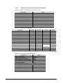
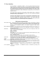
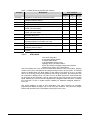
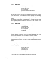
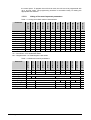


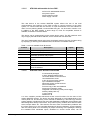
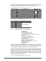

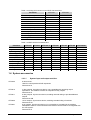


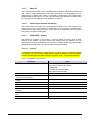

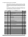
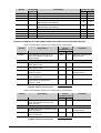

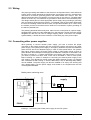
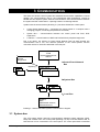
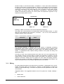
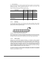
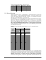
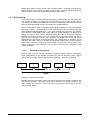
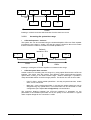
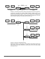
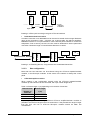
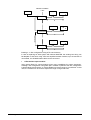
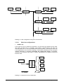

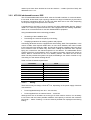
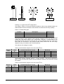
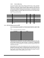
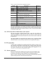
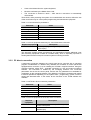
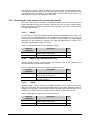

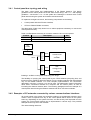
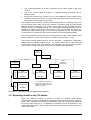
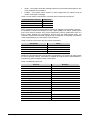

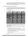
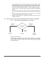

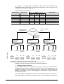
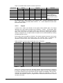
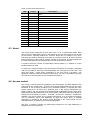
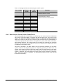
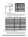

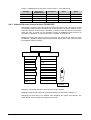
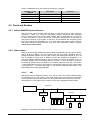
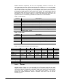
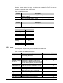

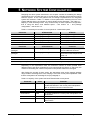
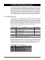
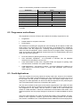


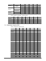


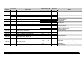
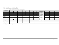


![取扱説明書[EZ4543] (1.77 MB/PDF)](http://vs1.manualzilla.com/store/data/006707967_2-f063635cf35f656a1f0c7572c5d8c9c9-150x150.png)