1
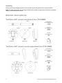
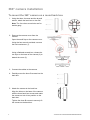
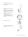
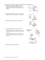
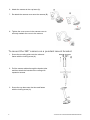
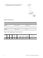
TruVision 360° Camera
Bracket Installation Manual
P/N 1072843A-EN • REV 1.0 • ISS 25SEP14
Copyright
© 2014 United Technologies Corporation.
Interlogix is part of UTC Building & Industrial Systems, a unit of United Technologies Corporation. All rights
reserved.
Trademarks and patents
Trade names used in this document may be trademarks or registered trademarks of the manufacturers or
vendors of the respective products.
Certification
N4131
2002/96/EC (WEEE directive): Products marked with this symbol cannot be disposed of as unsorted municipal
waste in the European Union. For proper recycling, return this product to your local supplier upon the purchase
of equivalent new equipment, or dispose of it at designated collection points. For more information see:
www.recyclethis.info.
Contact information
For contact information, see www.utcfireandsecurity.com or www.utcfssecurityproducts.eu.
Content
Introduction 1
Bracket descriptions 2
TruVision 360° camera round back box (TVF-BBM) 2
TruVision 360° camera round angled back box (TVF-WBM) 2
TruVision 360° camera cup base back box (TVF-CBM) 3
TruVision dome swan neck bracket (TVD-SNB) 3
TruVision dome pendant mount bracket (TVD-PPB) 3
360° camera installation 4
To mount the 360° camera on a round back box 4
To mount the 360° camera on a round angled back box 5
To mount the 360° camera on a swan neck bracket 7
To mount the 360° camera on a pendant mount bracket 8
Specifications 10
Pipe threading information 10
Introduction
These are the installation instructions for the TruVision 360° camera bracket models.
Models
SKU
Description
TVF-BBM
TruVision 360° Camera Round Back Box, Conduit Ports, Gang Box Compatible, Metal,
Indoor & Outdoor
TVF-WBM
TruVision 360° Camera Round Angled Back Box, Conduit Ports, Gang Box Compatible,
Metal, Indoor & Outdoor
TVF-CBM
TruVision 360° Camera Cup Base (use with TVD-PPB for pendant mount or TVD-SNB for
wall mount)
TVD-SNB
TruVision Dome Swan Neck Bracket
TVD-PPB
TruVision Dome Pendant Mount Bracket
Packet contents
The package contains the following items:
•
Bracket
•
Accessories for installation
•
Screws
TruVision 360° Camera Bracket Installation Manual
1
Unpacking
Please check the package contents to ensure that all parts are present and in good condition.
Note: For safety purposes, the mounting surface must be able to support three times the combined
weight of the bracket and camera.
Bracket descriptions
TruVision 360° camera round back box (TVF-BBM)
Drywall anchor
Φ7.5 x 24.5mm (4 pcs)
Screw A
Φ4 x 25mm (4 pcs)
Screw B
Φ4 x 10mm (3 pcs)
Plug
Inside view
Outside view
Side view
TruVision 360° camera round angled back box (TVF-WBM)
Drywall anchor
Φ7.5 x 24.5mm (4 pcs)
Screw A
Φ4 x 25mm (4 pcs)
Screw B
Φ4 x 10mm (3 pcs)
Cable gland
Inside view
2
Outside view
TruVision 360° Camera Bracket Installation Manual
TruVision 360° camera cup base back box (TVF-CBM)
Screw B
Φ4 x 10mm (3 pcs)
TruVision dome swan neck bracket (TVD-SNB)
Expansion screw
Ø 10 mm (5 pcs)
Locking screw
Ø 4 mm (2 pcs)
TruVision dome pendant mount bracket (TVD-PPB)
Expansion screw
Ø 10 mm (5 pcs)
Locking screw
Ø 4 mm (5 pcs)
1. Mounting plate
TruVision 360° Camera Bracket Installation Manual
2. Tube
3
360° camera installation
To mount the 360° camera on a round back box
1. Using the three A screws and the drywall
anchor, attach the back box to the wall.
Note: The four other screw holes are for
double gang.
2. Remove the camera cover from the
camera.
Open the small flap on the camera cover.
Using the hex wrench provided, unscrew
the hex head screw (1).
Using a flathead screwdriver, release the
two clips on the base of the camera (2) to
detach the cover (3).
3. Connect the cables to the camera.
4. Partially screw the three B screws into the
back box.
5. Attach the camera to the back box.
Align the holes on the base of the camera
with the three back box screws and rotate
the camera to lock it into position on the
back box.
Tighten the three B screws to securely fix
the camera to the back box.
4
TruVision 360° Camera Bracket Installation Manual
Important: When mounting the camera to
the back box, ensure that the ‘UP’
reference on the camera base is pointing
upwards.
6. Re-attach the camera cover.
7. Tighten the cover screw in the camera
cover to securely reattach cover to the
camera.
To mount the 360° camera on a round angled back box
1. Using the three A screws and the drywall
anchor, attach the wedge back box to the
wall.
Note: The four other screw holes are for
double gang.
2. Remove the camera cover from the
camera.
Open the small flap on the camera cover.
Using the hex wrench provided, unscrew
the hex head screw (1).
Using a flathead screwdriver, release the
two clips on the base of the camera (2) to
detach the cover (3).
TruVision 360° Camera Bracket Installation Manual
5
3. Connect the cables to the camera.
4. Partially screw the three B screws into the
wedge back box.
5. Attach the camera to the round angled
back box.
Align the holes on the base of the camera
with the three back box screws and rotate
the camera to lock it into position on the
back box.
Tighten the three B screws to securely fix
the camera to the back box.
Important: When mounting the camera to
the back box, ensure that the ‘UP’
reference on the camera base is pointing
upwards.
6. Re-attach the camera cover.
7. Tighten the cover screw in the camera
cover to securely reattach the cover to the
camera.
6
TruVision 360° Camera Bracket Installation Manual
To mount the 360° camera on a swan neck bracket
1. Pull the camera cables through the TVD-SNB
bracket tube and then attach the swan neck
bracket to the wall with the expansion screws (A)
provided.
2. Screw the cup base onto the swan neck bracket
and fasten with the locking screw, as shown (A).
3. Screw the three B screws into the cup base.
4. Remove the camera cover from the camera.
Open the small flap on the camera cover. Using
the hex wrench provided, unscrew the hex head
screw (1).
Using a flathead screwdriver, release the two
clips on the base of the camera (2) to detach the
cover (3).
5. Connect the cables to the camera.
TruVision 360° Camera Bracket Installation Manual
7
6. Attach the camera to the cup base (A).
7. Re-attach the camera cover onto the camera (B).
8. Tighten the cover screw in the camera cover to
securely reattach the cover to the camera.
To mount the 360° camera on a pendant mount bracket
1. Screw the mounting plate onto the tube and
fasten with the locking screw (A).
2. Pull the camera cables through the bracket tube
and then attach the bracket to the ceiling with
expansion screws.
3. Screw the cup base onto the tube and fasten
with the locking screw (A).
8
TruVision 360° Camera Bracket Installation Manual
4. Partially screw the three B screws into the
pendant bracket.
5. Connect the cables to the camera.
6. Remove the camera cover from the camera.
Open the small flap on the camera cover. Using
the hex wrench provided, unscrew the hex head
screw (1).
Using a flathead screwdriver, tighten the two
clips on the base of the camera (2) to detach the
cover (3).
7. Attach the camera to the cup base (A).
8. Re-attach the camera cover onto the camera (B).
TruVision 360° Camera Bracket Installation Manual
9
9. Tighten the cover screw in the camera cover to
securely reattach the cover to the camera.
Specifications
SKU
Dimensions
Weight
TVD-SNB
253 × 95 × 180 mm
490 g (1.2 lb)
TVD-PPB
Ø 150 × 537 mm
1169 g (2.56 lb)
TVF-BBM
Ø 168 × 42 mm
337.5 g
TVF-WBM
Ø 168 × 49 mm
304.5 g
TVF-CBM
Ø 179 × 86 mm
542 g
Pipe threading information
Pipe
thread
size
G1
10
Threads
/ in
11
Pitch
(mm)
2.309
Thread major
diameter
Corresponding pipe
Tapping drill size (mm)
(mm)
(in.)
DN
OD
(mm)
OD
(in.)
Thickness
(mm)
BSP. F (G)
33.249
1.309
25
33.7
1.33
3.2
30.75
TruVision 360° Camera Bracket Installation Manual