1
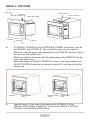
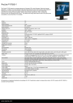
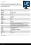
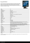
IO 00505
AMM 20 BI
Installation Manual
Microwave Oven
Before using the microwave, please carefully read this manual.
DEAR CUSTOMER,
Please read this manual carefully before you start to use this microwave. This way,
you can ensure its proper and correct operation.
Please preserve this manual and store it near the appliance, so that it is available
at all times for reference.
Observe the instructions contained herein to prevent accidents.
Before using the microwave, please carefully read this manual. Store it in such a place,
so that it may be used in future. Please
follow the instructions to ensure many years
of reliable operation of your oven.
Important!
The appliance is designed for household use only.
The manufacturer reserves the right to introduce changes which do not affect the
operation of the appliance.
3
EQUIPMENT
ADJUST SCREW A
SCREW B
SCREW C
TRIM-KIT PLASTIC
COVER
Frame
Electrical connection
The oven is fitted with a plug and must be only connected to a properly installed earthed socket. In accordance with the appropriate regulations, the socket must only be
installed and the connecting cable must only be replaced by a qualified electrician. If
the plug is no longer accessible following installation and all-pole isolating switch must
be present on the installation side with a contact gap of at least 3mm.
BUILT-IN FURNITURE
The built-in cabinet shall not have a rear wall behind the appliance.
Minimum installation height is 85cm.
Do not cover ventilation slots and air intake points.
4
BUILT-IN FURNITURE
3. INSTALL THE OVEN
a) Turn over the oven and install LONG
FEET provided in the accessory package.
LONG FEET
5
INSTALL THE OVEN
SCREW B
ADJUST HEIGHT
SCREW B
ADJUST SCREW A
SCREW B
b)
TRIM KIT
TRIM-KIT
SCREW B
Fix ADJSUT SCREW A on the UPPER AIR TUNNEL of the oven, and fix
the TRIM KIT with SCREW B. Then install the oven into the cabinet.
Make sure that the upper side gap between the TRIM KIT and the oven is
the same as the bottom side.
Make sure that the minimum left side gap between the TRIM KIT and the
oven is at least 9 mm.
Adjust the height of ADJUST SCREW A to keep 1 mm gap between the
ADJUST SCREW A and the top plane of cabinet. Do not trap or kink the
power cord.
SCREW C
c)
ADJUST SCREW A
UPPER AIR TUNNEL
TRIM-KIT PLASTIC
COVER
INSTALLATION
HOLE
INSTALLATION
HOLE
Open the door; fix the oven in the cabinet with SCREW C at the
INSTALLATION HOLE of TRIM KIT. Then fix the TRIM-KIT PLASTIC
COVER to the INSTALLATION HOLE.
6
7
IO 00505