1
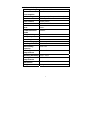
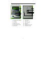
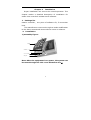
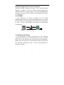
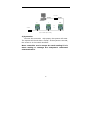
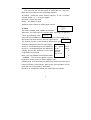
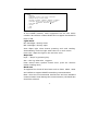
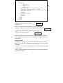
AC-201
RFID Access controller
User Manual
Content
Chapter one - Product introduction
Main function features
----------------------------------------------------1
Main technical parameter
----------------------------------------------------2
Structure description
----------------------------------------------------3
Fast Index
----------------------------------------------------5
Chapter Two – Installation
Package list ----------------------------------------------------------------------8
Install
--------------------------------------------------------------------------8
Operation -------------------------------------------------------------------------9
Chapter 3 – System setting
clock -----------------------------------------------------------------------------11
card ------------------------------------------------------------------------------13
system ---------------------------------------------------------------------------13
door
----------------------------------------------------------------------------16
port ------------------------------------------------------------------------------18
menu language ------------------------------------------------------------------19
short message
-----------------------------------------------------------------20
Name and work number ---------------------------------------------------------20
Appendix
Appendix A – Port and extended signal ----------------------------------------21
Appendix B – Authority Description ---------------------------------------------23
Appendix C
A.P.B description
---------------------------------------------24
Statement: The manufacturer reserves the right to change the technology and
specification without notice in advance.
Chapter one Production introduction
This is integrated with time recorder, PWD door controller,
single-door controller, reader with Chinese character display
and double door controller. It is widely used in door controller,
time recorder, real-time patrol and parking lot etc.
1. Main function features
1) All-purpose and wide application
The product is integrated with PWD keyboard, reader in
Chinese, single door controller, time recorder and double
door controller. It is optional of button and no button,
computer white and champagne color. The product is a
new-generation production with high performance rate
that can meet various customers’ demand.
2) Advanced technology, stable and reliable.
All input and output pots can prevent shock from static
and power. It has strong anti-interference ability and has
power failure resisting design. The PCB board has
moisture proof and corrosion protection and can adapt to
different rough whether.
3) Dynamic definition, flexible application
One build-in card reader (EM or Mifare), two sets of W26
interface, two sets of sensor input, two sets of button
input, two sets of relay output, one set of bell port and
one set of RS485 communication interface.
Re-define the IO interface. For example, W26 port will be
defined as W26 standard output or input, the relay can be
defined as door controller, bell or alm output, the sensor
can be defined as fire alm signal.
Support hardware updata on-line
1
4). Chinese-English menu, easy application
Chinese-English Menu port with light, display the owner’s
name and work number.
Issue public short message and personal short message
16 alm times are available. The alm supports working day
setting
The clock modification parameter can ensure the
correction of time for a long time.
It can be networked (255 sets at most) and also be in
off-line. It can complete the parameter setting by
keyboard when is in off-line.
5) Professional door controller, powerful function
Door control: 2 doors, standard wiegand 26 interface. It
can connect with world famous reader such as HID and
Motorola.
Support 2500 card holders and store 25000 pieces of
card reading information and alm events.
32 time periods/64 time sets/16 application groups/8
types of holidays/validity period for card/card PIN (6
numbers)
The product has two layers of A.P.B and mutual lock when
the hardware is off-line. (Open only one door for each
time)
Only PIN, only card and card & PIN are available. It can
also support duress PIN and super PIN.
Soft control of any door, various alm incidents functions:
open time-out, close time-out, intrude alm, force alm,
burglar alm and fire alm etc.
2
2. Main technical parameter
Working voltage
Power
AC/DC 8~25V
<1W
consumption
Data saving
>10 years (after power failure)
Total records
25000 pieces
Card control
2000 pieces
LCD resolution
122×32 DOTS
Build-in
16×16 national class two character
word
base
base.
Communication
RS485
mode
Wiegand 26 port
Two
Relay output
Two
State input
Four
Card reading type
EM compatible
Reading distance
5—10cm
Networking
255 sets
capacity
Working
-20℃—70℃
temperature
Working humidity
20%—90%
Storage
-25℃—85℃
temperature
Dimension
L120×W88×H 18mm
Weight
160g
3
3. Structure description
1
7
8
2
9
10
11
3
4
5
12
6
1、Liquid crystal display
7、 rear patch
2、indicator
8、 W26 port x 2
3、keyboard
9、 main I/O port
4、black front cover
10、Bell Port
5、card induction area
11、RS458 comm. port
6、bell button
12、installation hole
4
4. Fast index list
1) Display icon index
Icon
Meaning
Current option
v
There is some information following, press <
9 > to review.
u
There is some information above, press < 7
> to review.
There is no chosen item in the check box.
There is chosen item in the check box.
There is no chosen item in the radio button.
There is chosen item in the radio button.
2) Keyboard function index
Key
Function
< 0 >< 1 >< 2>
Number input
< 3 >< 4 >< 5 >
< 6 >< 8 >
<7>
Number input or
Up
<9>
Number input or
Down
<*>
Cancel the operation
Return to the high-authority menu
Escape multiple choice or single
choice and save the choice.
<#>
Confirm the operation
Enter into the submenu
Choose multiple choices or single
choice.
5
3) Main menu index:
Menu_Main
|—clock
|
|—set time
|
|—adj time
|
|
|—
|
|
|—
adj fast
|
|—
adj slow
adj not
|
|
|
|—alm
|
|
|— alm 01->
|
|
|
|— enable
|
|
|
|—alarm
|
|
|
|—delay
|
|
|
|—weekset
|
|
| 。
|
|
| 。
|
|
|—
|
|
|
Sun
Mon…
Sat
alm 16->
(Ditto)
| Card
|
|—add card
|
|—update card
|
|—Del card
|
|—system
|
|—Model ID
|—light mode— NC、 NO、 Auto、 time zone
|
|
|—beep hint— keys、
|
|—baud rate— 2400bps、 4800bps、 9600bps、 19200bps
clock、
|
|—Rec option—
|
|—menu PWD
|
|—Sys info
|
|—clear…
|
|—updata…
in rec、
hints,
out rec、
event rec、
cycle、
sameness、
tot alarm、 5-digit
|—door
|
|—DR 1
|
|
|—authority
|
|
|
|
|
|
|—time zone—(0-63)
|
|
|
|—holiday
|—APPset—( 0-15)
|—timer—(0-31)
|
|
|
|
|
|——control mode
|
|
|
in and out、
only card、
|—entry mode—
|
sensor NO、
|—sensor type—
|
|
|—button— NO、 NC、 null
|
|
|—close time
|
|
only in、
only PIN、
any out 、 A.P.B.
card &PIN
sensor NC、
fire NO、 fire NC、
|—open time
ON、
|
|
|—first NO—
|
|
|—duress PIN
|
|
|—access PIN|
|
|—DR 2
|
|
|
|—
DR 1->2
|
|—
DR 2->1
OFF
|
(Ditto)
|—port
|
|—relay 1—
lock 1、
lock 2、
bell、
alm 、
null
|
|—relay 2—
lock 1、
lock 2、
bell、
alm 、
null,
|
|
|——W26 port
|
|—W26 port
1
in 1、
out 1、
in 2、
out 2、
W26 out 、
null,
2—
in 1、
out 1、
in 2、
out 2、
W26 out 、
null
|—Local reading—
| Language
Chinese
in 1、
out 1、
English
in 2、
out 2、 null
6
null
Operation index for common keys
Go to Setup Menu
Press <*> and <#> (<*> first, then <#> soon after) at
the initial state to enter into the menu state.
Menu Browse
The menu is in tree structure. In some submenu, <7> and
<9> are used to choose the items up and down. The chosen
item will be in white display (white letter on a black ground).
Press <#> key to fix the item setting and press <*> to
cancel the item setting and return to the high-authority
menu. the system will automatically escape from the menu
and restore the initial interface.
Multiple choices and single choice
<7> key is to review upward, <9> key is to review downward;
<#> key is to choose multiple choices or single choice; < * >
key is to escape the multiple choice or single choice and save
the choice result.
PIN entry - Applied to the Access PIN or Duress PIN
Press <#> at the initial state and the screen displays the
prompt to enter the PWD . Enter the PWD (from <0> to <9>),
and press <#> key to confirm.
PWD update - Applied to the card & PIN
Read card and press the valid PWD , then press <*> and
<#> quickly, read card again at the sight of the prompt.
Enter the new PWD two times. The PIN update is successful.
(Default PWD is: 888888)
7
Chapter 2
Installation
Proper installation can ensure the normal operation. This
chapter makes a detailed description of installation for
smart time recorder’s hardware and software.
1.
Package list
master controller , one piece of software CD, 5 connection
lines.
The manufacturer reserves the right to make modification
to the above-mentioned items without notice in advance.
2.
Installation
1) assembly figure:
Cover
Installation
cover
fixed
dismount
1
rear patch
Note: After the equipment is on power, the system can
be reset through the side cover dismount slot 1.
8
2) Networking with the control computer
provides RS485 networking mode. The communication
distance is 1200m. It can be used for single machine or
multiple-machine communication and need RS232/RS422
converter to connect with computer. See detailed connection
in “Appendix A”.
2.1.1 RS485
The connection is shown as figure 2-2. It needs
RS232/RS422 converter to connect RS485 port (JP1 or JP2)
of time recorder. It is advisable to set the terminal resistance
of 120Ω, for the long distance will results in great signal
consumption.
<15 米
<1200 米
RS232
RS485
converter
JP4
Terminal
Figure 2-2 RS485 single networking
2.2 Multiple networking
The connection is shown as figure 2-3. The multiple
networking realizes by the connection with one in and the
other out of JP1 and JP2 (JP1 and JP2 can be exchanged).
Please refer to the figure. The terminal should connect with
the terminal resistance of 120Ω. And its total distance is
limited to 1200m.
9
Converter
RS485
RS232
1
0
254
…
…
Terminal
Figure 2-3 RS485 multiple networking
4) Operation
Connect the controller
with power, the system will reset.
The system will check after a “beep”. If the systme is normal,
the screen is in the initial interface.
Note: controller won’t accept the card reading if it is
menu setting or manage the computer’s continutal
communication.
10
Chapter 3 System
This chapter mainly introduces how to set the system
parameters.There two ways are valaiable: keyboard and
operating
control software.
1.Clock
Menu_Main
|—clock
|
|—set time
|
|—adj time
|
|
|— adj not
|
|
|— adj fast
|
|
|— adj slow
|
|
|
|—alarm
|
|
|—alm 01->
|
|
|
|— enable
|
|
|
|—alarm
|
|
|
|—delay
|
|
|
|—weekset—
|
|
|
|—alm 16->
Sun、
Mon 一…
Sat
Set time
After a long time operation, the system’s time may be
incorrect. So it is necessary to adjsut the time. (the time is in 24
Hours fomat. )
The set information display is shown as the right figure.
12:00:00
August 1, 2003
Adj time
This is used to adjust the time automatically to minimize the
error after a long time operation.
Adj not——no system adjustment
Adj fast——the right figure displays after
entering and then enter the adjustment value.,
-
Adjust fast
00 (second/day)
Adj slow——the right figure displays after entering and then
adjust slow
00 (second/day)
enter the adjustmetn value.
11
Alarm
The user can set 16 alm times at most (alm 01—alm 16).
Each alm time should cover following aspects:
enable —hook-like mark means starting. If not, it means
closing. Press < # > to cycle trigger.
Alm time—input alm time
Delay —the delay for alm
weekset-it can choose in which days it alm s.
Menu_Main
|—card
|
|—add card
|
|—update card
|
|—Del card
2. Card
The card includes: add, update and delete.
Add card: The right figure is shown after entering. To get the
“card” by stamping card.
Wait reading card
If the card to be added is not valaible at your hand, press < # >
and enter the card directly. See the right figure.
The system will be in the authority distribution port
card being acquired. See the right figure.
Group 1—corresponding to the APPset of
Group 2-- corresponding to the APPset of
Validity period—All authority of the card
invalid after the period.
Note: the new added card’s default PWD
Please enter card PIN
00000000
after the
Group
1
00 group
2 00
validity
period
:
99-12-31
DR 1
DR 2
is
is
“888888”. The user can update it on the
keyboard. Please refer to “PWD update” part.
Update card: It is necessary to update the authority of the card
having existed in the system. After entry, the operation is the
same as that of the above “add card”.
Delcard: to completely delete the card from the system.
12
3. System - To set system parameter
Menu_Main
|—system
|
|—Model ID
|
|—Light mode— close、 NO、 auto、 time zone
|
|—Beep hint— keys、 clock、 hints
|
|—baud rate— 2400bps、 4800bps、 9600bps、 19200bps
|
|—Rec option— in rec、 out rec、 event rec、 cycle、
sameness、 tot alarm、 5 digit
|
|—menu PWD
|—Sys info
|—clear…
|—updata….
Model ID
In the RS485 network, each equipment has its own series
number. We call this number Model ID. It support the Model ID
from 0-254.
Light mode
NC—backlight—directly close
NO—backlight—directly open
Auto—Open light when button pressing and card reading.
Automatically close the light when there is no such event.
time zone—Open the light in the set time zone.
Beep hint
keys---“beep” by pressing key.
alm —alm ing when alm
triggers.
hints—sound when system events occur (such as: exterior
reader reading card)
Baud rate
It supports four kinds of baud rate such as 2400、4800、9600
and 19200 to support RS485 networking communication.
Note: when the environmental interference and non-standard
communication lines damage the communication, the baud rate
should be reduced.
13
Record option
In rec—recing in card reading
Out rec—recing out card reading
Event rec—including software open rec, PWD open rec, intrude
rec, fire alm rec, button rec, duress rec, and clear rec etc.
Cycle—to cover the oldest recwhen the reccapacity is full.
No sameness-not recorde the card reading of the same card in
the same site repeatedly in one minute.
capacity pre-alert--- it can trigger the alert after it being chosen.
The port
is shown as follow.
Set alm
capacity 95%
5-digit card number--not choose default and read the 8-digit;
choose to read the 5 digit
Menu PWD
The PIN to entering into the main menu is made up of 6 digits at
most, Follows the steps shown below.
modify PWD
old PWD ******
modify PWD
modify PWD
new PWD ******
new password******
Firstly, enter the former valid PWD, then enter the new PWD
two times. The PWD update is successful. To lift PWD , just to
enter no number to the new PWD . When entering a number,
press < * > to clear it and press < # > to confirm.
Note: It is advisable to set PWD when it is used. (the default is
Sys info
It is used to display rec of events, the number of registered card
00% rec00002
and occupied storage volume.
00% card 00000
14
Clear
It can clear the three following datas: system setting, card
register and event rec.
restore the default
Confirm?
Del all event rec
Del all cards
Confirm?
Confirm?
To clear according to the actual requirement. Press <#> to
confirm the clear, and press <*> to cancell the clear.
Updata
supports hardware updata on-line. The steps are shown as
follow:
1.
communication
port
connects
with
computer
by
RS485/RS232 converter.
2. When it is in the updata standby state, the operation is
shown as follow: system ->updata.
Install “JS Updata tool for hardware” in the computer. Operate
JS Updata.exe, communication port should choose correct
interface, the baud rate is 19200, the updata file should be the
xxxxx.upd updata file provided by the manufacturer. When the
updata starts, progress bar indicates the course of updata.
Please do not interrupt the course. After the updata, terminal
computer will reboot.
15
Menu_Main
|—door
|
|—DR 1
|
|—authority
|
|
|
|—timer—(0-31))
|
|
|
|—time zone—(0-63)
|
|
|
|—holiday
|
|
|
|—APPSet—(0-15)
|
|
|—control mode— in and out、 only in、 any out 、 A.P.B.
|
|
|—entry mode— only card、 only PIN、 card &PIN
|
|
|—Sensor type— sensor NO、 sensor NC、 fire NO、 fire NC、 null
|
|—button— NO、 NC、 null
|
|
|—open time
|
|
|—close time
|
|
|—first NO— ON、 OFF
-,
|
|
|—duress PIN
|
|
|—access PIN
|
|—set DR 2
|
|
(Ditto)
|
|—DR 1->2
|
|—DR 2->1
4. door
supports double-door controller
Authority
00:00 -> 00:00 00
00:00 -> 00:00 01 v
Timer—support 32 time periods. See the right figure.
Timeset—support 64 time zones. See the right figure.
31 00 00 00 00
31 00 00 00 01 v
Holiday—pre-set holiday authority type in one
Year. See the right picture.
Date:
MM
Type:
00 (00-07)
DD
port 16 groups. The group mentioned in the card is set here.
See detailed authority structure in Appendix B about authority
description.
Control mode
In and out --in and out are strictly managed by the authority.
Only in—in is strictly managed by the authority. The out reader
is invalid.
Any out--- in is strictly managed by the authority and out just
reading card.
A.P.B---out by stamping card is valid only in the case of being in
by stamping card.
16
Entry mode
Card only ---verify the card’s authority.
PIN only---in by entering valid access PIN or duress PIN.
Card & PIN—verify the card’s authority and enter valid PWD.
Sensor type
Sensor NO—signal is in short circuit to the ground, which
indicates there is sensor signal. And the door opens.
Door NC—signal is in open circuit to the ground, which indicates
there is door switch. And the door opens.
Fire NO—signal is in short circuit to the ground, which indicates
there is fire signal. And it triggers the fire alm .
Fire NC—signal is in open circuit to the ground, which indicates
there is fire signal. And it triggers the fire alm .
Null----the signal is invalid.
Button
NO—signal is in short circuit to the ground, which indicates the
button is pressed.
NC---signal is in open circuit to the ground, which indicates the
button is pressed.
Null---signal is invalid.
Open time
It is the duration of unlocking when going in normally. If the
open signal of sensor is founded during the time,
the
controller will close the lock at once. Otherwise, the controller
will close the lock till the open time.
Close time
It is the time from door open to close. In another word, the
time from system detecting open signal to close signal is called
close time. If the close time is over the set value, the system
will alm
to warn the user to close door.
Note: the above funtion is only available for door with sensor.
17
First NO
Within the set control time of first group, if there is a normal
and valid open, the door will keep open till the controltime is up.
For example, the gate setting in the factory, it opens during
working time and closes after work.
Duress PIN
When the seized by burglar, the user can press the PWD to
open door. And the system will keep a duress event rec the
monitor computer will display the rec. If the setting is empty,
the PWD is invalid.
Access PIN
The PWD is used to open door directly. If the setting is empty,
the PWD is invalid.
Set DR 2
The operation is the same as the above.
DR 1->2
Copy all setting of DR 1 to the DR 2.
DR
2->1
Copy all setting of DR 2 to the DR 1.
5. Port
Menu_Main
|—port setting
|
|—relay 1— lock 1、 lock 2、 bell、 alm 、 null
|
|—relay 2— lock 1、 lock 2、 bell、 alm 、 null
|
|—W26 port 1— in 1、 out 1、 in 2、 out 2、 W 26 out、 null,
|
|—W26 port 2— in 1、 out 1、 in 2、 out 2、 W26 out、 null,
| |—Local reading— in 1、 out 1、 in 2、 out 2、 null
The user can properly configurate the interfaces (relay, W26
port
and reader of the machine)provided by the system
according to their own application demand.
18
Relay 1
Lock 1---- linking with electric lock control of DR 1
lock 2—linking with electric lock control of DR 2
bell--- linking with alm
alm ---link with alm
control of alm
event (such as illegal intrude etc)
Null---signal is invalid.
relay 2: ditto
W26 port
1
In 1---the port connects with standard W26 reader and controls
in of DR 1.
Out 1---the port connects with standard W26 reader and
controls out of DR 1.
In 2---the port connects with standard W26 reader and controls
in of DR 2.
Out 2---the port connects with standard W26 reader and
controls out of DR 2.
W26 out---the card reading employs standard W26 out.
Therefore, it can be used as reader.
Null---signal is invalid.
W26 port
2
Ditto
Self reader
It is the same as W26 port 1, 2 except for the W26 output.
6. Language
Menu-Main
|—Language—
Chinese、 English
Chinese and English are optional.
19
7. Short message
The user can send some short word message (100 Chinese
characters or 200 English letters) to the LCD screen
, such as:
notice the company and advertisement etc. The system
displays the message on the screen. If it isn’t displayed in one
line, it is be displayed in roll. The message has two kinds: public
message and personal message. The public message will
automatically display on the screen if the sending time is valid.
While, the personal message is only displayed after the
designated card is stamped.
Note:
The
short
message
is
only
sent
by
the
controlcomputer.
8. Name and work number
The name and work number of employee is sent to the time
recer by the controlcomputer. The name is made up of 8 English
letters or 4 Chinese characters at most, and the number is
made up of 11 English letters and digits at most.
Note: The name and number can be only sent by the control
computer.
20
Appendix A Port and extended signal
JP2
1
JP3
4
1
1
10
1 3
12
JP4
JP5
Description for JP1 port signal
Terminal Signal
Color
1
+V
red
2
3
4
5
6
7
8
9
10
GND
MC1
OP1
MC2
OP2
LS1
LS1
LS2
LS2
4
black
green
yellow
white
brown
blue
purple
orange
gray
JP1
Remark
Positive power terminal
(+12DCV)
Power ground
Sensor 1
Button 1
Sensor 2
Button 2
Relay output 1
Relay output 2
Description for JP2, JP3 port signal
Terminal Signal
Color
Remark
1
+V
red
Positive power terminal
2
GND
black
Power ground
3
DATA0
green
W26 data line
4
DATA1
yellow
W26 data line
21
Description for JP4 port signal
Terminal
1
2
Signal
GND
RS485-
Color
black
green
3
RS485+
yellow
Description for JP5
Terminal Signal
1
GND
2
Bell
Remark
Power ground
Negative
communication
Positive
communication
port signal
Color
white
gray
Wiegand
26
Optio
l
reader
bell
RS485
Remark
bell switch signal (NO)
Wiegand
alm
RS485
Optio
l
Electr
Button
JP3
JP2
Sensor or fire
alm input
A
1
V
4
1
1
Sensor or fire
alm input
4
10
JP1
DC
1 3
JP4
RS458 总线
RS232
RS232/RS458 converter
connect next EF
22
12
JP5
Bell
Appendix B authority description
Setting steps:
1. Set timer>> set Time zone>> set holiday >> set APPset
00-15.
2. Card -> add card or update card, set the validity period of the
card and distribute corresponding APPset to the two doors.
Authority
User App Group 00
. . .
. . .
. . .
User App Group 15
User Group
Time Zone
Day
#
Sunday
00
Monday 00
…
Saturaday 00
Holiday
Groop 1
…
Group 7
Door 1 Group
00——15
Door 2 Group
00——15
Time Zone
4 Time Zone
00 00 00 00
. . . .
. . . .
. . . .
00 00 00 00
#
00
.
.
.
63
Valid peropd
PIN
Card
Time Zone List
Start
End
#
00:00 ->00:00 00
.
.
.
.
.
.
.
.
.
00:00 ->00:00 31
00
00
Holiday
Date
Type
00 月 00 日 00
.
.
.
Remarks :
Bold letter – user define
data
Parameters
Example setting
e.g 1
24 hrs
User App group
Set all
00
Time Zone
00 00 00 00
00
Time slot
00:00 ->23:59
00
E.g 2
Monday —— Friday :
8:00——12:00 14:00——17:00 20:00——23:30 (3 time slot can entry)
Saturday - 12:00 can entry only
Sunday & Holiday :All day can’t entry
User app Group
Sunday
00
Monday
01
Tuesday
01
Wednesday 01
Thursday 01
Friday
01
Saturday 02
Holiday0
00
Time Zone
00 00 00 00
01 02 03 00
01 00 00 00
00
01
02
Holiday
Date
Type
10 月 01 日 00
23
Time slot
00:00 ->00:00
08:00 ->12:00
14:00 ->17:00
20:00 ->23:30
00
01
02
03
Appendix C A.P.B description
Requirement 1. The one who enters by reading card is
permitted be out by reading card.
Setting steps
1. Port ->W26 port 1 (set as in 1)
->W26 port 2 (set as out 1)
2. DR 1 -> control mode (set as A.P.B)
Requirement 2. There is one entry and one exit in one parking
lot. The card reading is necessary when entering and going out
the lot. But the vehicle that isn’t registered by card reading in
the entry is forbidden to park in the lot.
Setting steps:
1. Port -> W26 port
(set as in 1)
-> W26 port 2 (set in 2)
2. DR 1 -> control mode (set as A.P.B)
3. Set DR 2 -> control mode (set as A.P.B)
24