1
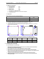
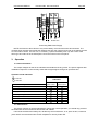
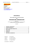
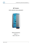
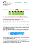
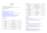
User Manual ZMS-xA
Document No. 0573.00.95-02.0
Page 1/6
MERAWEX Sp. z o.o
44-122 Gliwice
ul. Toruńska 8
tel. 032 23 99 400
fax 032 23 99 409
e-mail: [email protected]
http://www.merawex.com.pl
USER MANUAL
CAMELEON BOX Uninterruptible Power Supply in IP44 wall cabinet
15 May 2014
1.
TECHNICAL DESCRIPTION
2
2
INSTALLATION AND CONNECTION
3
3. OPERATION
5
4.
SERVICING
6
5.
RALATED DOCUMENTS.
6
6.
DISPOSAL OF PACKAGING, USED PRODUCTS AND BATTERIES WORN.
6
Prepared by:
Franciszek Szwedowicz
Evaluated by:
Dariusz Cygankiewicz
Verified by: Zdzisław Klimasara
Accepted by:
Grzegorz Szandar
Document No.: 0573.00.95-02.0
User Manual ZMS-xA
Document No. 0573.00.95-02.0
Page 2/6
Safety Precautions
Please read this User Manual, before starting operation.
Do not touch the internal components of the unit in operation - danger of electric shock
or burns.
Protect the device from getting of any objects or liquids into the interior - threatening of
electric shock and damage to the equipment.
Do not cover the ventilation holes – it can lead to damage of the device.
Please, keep the free space of at least 10 cm on the sides of the device to enable the
proper ventilation.
It is forbidden to carry and transport the device with mounted and attached batteries.
The power supply must be powered from the mains with the earth terminal.
The device may interfere with radio and television sensitive equipment located nearby.
1. Technical description
1.1. Intended use
The CAMELEON BOX power supplies with the battery cooperation capability supply the
uninterruptible voltage from the 230V +10% -15%, 50Hz mains or from the internal VRLA lead-acid (the
AGM or gel) batteries when the mains failure. When switching from the mains supply into the battery
operation, temporary voltage decays cannot be observed.
The power supplies are equipped with cables for connecting batteries but batteries should be
ordered separately.
Type of power
supply
CAMELEON BOX
Output
voltage
Max. output
current
ZMS-1A-12V10A
ZMS-1A-12V12A
ZMS-1A-12V16A
ZMS-2A-12V10A
ZMS-2A-12V12A
ZMS-2A-12V16A
ZMS-3A-12V10A
ZMS-3A-12V12A
ZMS-3A-12V16A
ZMS-1A-24V6A
ZMS-1A-24V8A
ZMS-1A-24V12A
ZMS-2A-24V6A
ZMS-2A-24V8A
ZMS-2A-24V12A
ZMS-3A-24V6A
ZMS-3A-24V8A
ZMS-3A-24V12A
ZMS-1A-48V3A
ZMS-1A-48V4A
ZMS-1A-48V6A
ZMS-3A-48V3A
ZMS-3A-48V4A
ZMS-3A-48V6A
12V
12V
12V
12V
12V
12V
12V
12V
12V
24V
24V
24V
24V
24V
24V
24V
24V
24V
48V
48V
48V
48V
48V
48V
10A
12A
16A
10A
12A
16A
10A
12A
16A
6A
8A
12A
6A
8A
12A
6A
8A
12A
3A
4A
6A
3A
4A
6A
Max. battery
Cabinet
capacity
dimensions
Up to 36Ah*
390x350x90
Up to 56Ah*
390x350x140
Up to 80Ah*
450x350x180
18Ah
390x350x90
28Ah
390x350x140
40Ah
450x350x180
5Ah
390x350x90
12Ah
450x350x180
Type of internal
Power Supply
ZM12V10A-151A-00
ZM12V12A-200A-00
ZM12V16A-300A-00
ZM12V10A-151A-00
ZM12V12A-200A-00
ZM12V16A-300A-00
ZM12V10A-151A-00
ZM12V12A-200A-00
ZM12V16A-300A-00
ZM24V6A-151A-00
ZM24V8A-200A-00
ZM24V12A-300A-00
ZM24V6A-151A-00
ZM24V8A-200A-00
ZM24V12A-300A-00
ZM24V6A-151A-00
ZM24V8A-200A-00
ZM24V12A-300A-00
ZM48V3A-151A-00
ZM48V4A-200A-00
ZM48V6A-300A-00
ZM48V3A-151A-00
ZM48V4A-200A-00
ZM48V6A-300A-00
* The 12V version allows for parallel connection of a battery.
NOTE:
The table above includes the nominal output voltages. The ranges of the output voltages related with
the battery cooperation capability have been defined in the User Manual on the ZM Power Supply
and are shown on the data plates.
User Manual ZMS-xA
Document No. 0573.00.95-02.0
Page 3/6
1.2 Additional equipement
a. Cable gland PG9
- 1 pc.
b. Cable gland PG11
- 3 pcs.
c. Round cap Z9
- 1 pc.
d. Round cap Z11
- 1 pc.
e. Battery cables
- 1 set
f. User Manual on CAMELEON BOX
g. User Manual for CAMELEON universal Power Supplies
h. Temperature probe
1.3 Parameters
Basic electrical and environmental parameters
Nominal AC power voltage
Recommended working temperature
Ingress protection code EN 60529:1991+A1:2000
Protection class EN 60950-1:2006+A11:2009+A1:2010+A12:2011
184…230V…253V
50Hz
-20…+40°C
IP 44
I
1. For battery discharging the recommended range of temperature: -20…+40°C.
2. For battery charging the recommended range of temperature: 0…+40°C.
3. The User Manual on the ZM modular Power Supplies, supplied with the device, includes the
detailed electrical parameters.
B
E
B+40
8
M
ME RAW
EX
A
AW
WE
X
D
A
C
Dimensional drawing and mounting holes placement in the ZMS power supply.
Cabinet
type
1A
2A
3A
A
B
C
D
E
390
390
450
350
350
350
90
140
180
350
350
410
370
370
370
2 Installing and connecting
2.1 Recommendations and warnings
Mounting and installing the device must be done in accordance with the information
provided in the following User Manual.
Do not expose the device to high temperatures or direct sunlight.
Mounting and connecting must be done only when the batteries are disconnected.
When connecting the battery please pay attention to the compliance of the polarity of the
battery with the description on the connector.
The device must be powered from the mains with the earth protection terminal.
Before connecting the device to the mains, it is necessary to check the quality of all
connections made.
User Manual ZMS-xA
Document No. 0573.00.95-02.0
Page 4/6
2.2 Installing
An installation place of the power supply should be carefully chosen in such a way as not to expose
it to mechanical damage, and not to exceed the permissible parameters of temperature and air
humidity. Power supplies should be installed near devices they power to eliminate voltage drops.
The cabinet should be mounted at a wall using the four holes on the brackets fastened to the
corners of the rear side of the cabinet. The cabinet must be fastened to the wall with 4 dowels and steel
screws. Due to the big weight (batteries) it is recommended the use of steel sleeve anchors and steel
screws.
The place of the mounting holes is included in the point 1.3 ‘Technical Description’.
2.3 Battery selection criteria
When selecting the battery capacity, for the determined battery backup time, please, take into
consideration the power supply quiescent current consumption, which is:
• 12V – 100mA
• 24V – 35mA
• 48V – 25mA
Selection of the battery capacity must be based on the size of the casing and an output voltage of
12V, 24V or 48V. In the table, the maximum capacity has been defined for each value of the output
voltage, separately for each of the three sizes of the casings.
In the modular power supplies mounted inside cabinets, the factory preset charging current is
equal to 25% of the nominal output current. An installer or a user can select higher charging current in
relation to the nominal output current (50%, 75% or 100%), especially for batteries with higher capacity
to shorten their charging time. It is important to use the tips in the User Manual. This setting does not
require dismounting the power supply but sliding the switch available on the bottom panel of the casing
from the front panel.
NOTE: please, take into consideration that the charging current must not exceed 30% of the
battery capacity.
2.4 Connecting
Please, note that the device must be connected to a fixed installation using the protective cable. It is
recommended to equip the installation with an anti-surge protection circuit. It is possible to lead the
installation cables from the top through the PG11 glands (3 pcs.) and PG9 (1 pc.) located there. All
connections must be done according to the diagram located inside – on the cabinet door. If you do not
use one of the glands, its hole must be plugged with an additional cap delivered with the power supply.
The recommended cross-section of the 3-wire cable to connect the mains is 3 x 0.75 ... 1.5mm2.
The recommended output cable is LgY, which cross-section should be adapted to the value of the
output current and the distance from the receiver.
When connecting the remote indication it is recommended to use the 2-wire cable of the cross
section of 2 x 0.75mm2.
Please, insert the supplied temperature probe into the socket described TEMP PROBE and put it
next to the battery.
In addition, the potential-free relay indication contacts described MAINS FLT and BAT FLT are
accessible on the front panel of the power supply. To trigger the general fault indication, the both
terminals should be connected serially for the NO terminals or in parallel for the NC terminals. The
contacts are described on the figure on the front panel of the CAMELEON modular power supply, next
to the fault indication connector.
User Manual ZMS-xA
Document No. 0573.00.95-02.0
C3A
C10A
L
BAT
Page 5/6
OUT
N
PE
MAINS 230V
Connecting ZMS Power Supply
NOTE: the fuses as above function only as the battery circuit and the mains disconnectors. The
modular power supplies used inside the cabinet have their own specific fuses both in the battery as well
as in the mains circuits. The user can, if necessary, replace the battery fuse only with a fuse of the
same type and value as in the description next to the socket on the front panel.
3. Operation
3.1.Initial information
The output voltages as well as the indication thresholds are factory preset. The power supplies after
installation require the control of faulty states which might happen during their operation time.
Operation mode indication
- LED on
- LED off
Operation state
No voltage state
Mains on
LED
Indication
MAINS
green colour
FAULT
yellow colour
Battery operation (no mains or rectifier fault)
Low battery voltage
No battery
No battery circuit continuity
Battery fuse blown
3.2. Maintenance
The device requires no special maintenance. During the normal operation, you should only preserve
the cleanliness of the environment around the wall cabinet.
It should be noted that the battery life, declared by the manufacturer, is 10 years at 20°C, reaches 6
years at 25°C and decreases twice as the temperatur e rises by further 8°C.
User Manual ZMS-xA
Document No. 0573.00.95-02.0
Page 6/6
4. Servicing
•
User can only replace the battery fuse located on the front panel of the power
supply, inside the cabinet, on the fuse of the same type and current value. Types
and current values for the fuse for the specific internal power supplies are listed
in the User Manual for the CAMELEON Power Supplies, supplied with the
equipment.
•
All warranty and post-warranty service repairs should be realized by the service
staff of the Manufacturer or a specialized Company authorized by the
Manufacturer
5. Ralated documents.
•
The User Manual of the universal, modular CAMELEON Power Supplies No. 0351.00.95-01.2.
6. Disposal of packaging, used products and batteries.
Product packaging is made of non-hazardous materials (wood, paper, cardboard,
plastics), which can be recycled. Packages which are no longer needed should be
passed on to a waste collection station, after they had been sorted.
The used product is a non-hazardous waste which should not be disposed of in
the general waste bin, but it has to be transferred to the local waste
collection/recycling station accepting electric and electronic equipment.
Appropriate disposal of waste electrical devices will help to avoid harmful human
health and environmental impacts resulting from improper storage and processing of
such the equipment.
When disposing used batteries, please follow the rules contained in the "Act on
batteries and accumulators" of 24th April 2009 (Journal of Laws of 2009 No. 79,
item. 666). They are tight (equipped with a unidirectional, self-sealing valve),
maintenance-free lead-acid VRLA batteries classified in accordance with the Act to
the category of industrial batteries, which after their use are hazardous waste of the
code of 16 06 01* (Reg. of the Ministry of Infrastructure of 27th April 2001 on the
catalog of waste – Journal of Laws of 2001 No. 112, item 1206).