1
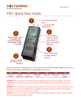
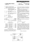
CAMELEON Power Supply Units User Manual Document No 0351.00.95-02.1 1/13 MERAWEX Sp. z o.o. 44-122 Gliwice ul. Toruńska 8 tel. (0-32) 239-94-00 fax (0-32) 239-94-09 [email protected] http://www.merawex.com.pl USER MANUAL CAMELEON - Universal modular power supplies with output voltage up to 60V 23.01.2014 Table of contents 1. 1.1. 1.2. 2. 3. 4. 5. 6. 7. 7.1. 7.2. 7.3. 7.4. SAFETY PRECAUTIONS ............................................................................................................ 2 ENVIRONMENTAL PROTECTION................................................................................................ 2 MANUFACTURER'S REMARKS .................................................................................................. 2 GENERAL DESCRIPTION AND INTENDED USE.............................................................................. 3 ELECTRICAL PARAMETERS ...................................................................................................... 3 OPERATING CONDITIONS ......................................................................................................... 3 OVERALL DIMENSIONS AND MOUNTING ..................................................................................... 4 CONNECTION .......................................................................................................................... 4 TYPES OF POWER SUPPLIES ................................................................................................... 5 SINGLE-OUTPUT POWER SUPPLIES .......................................................................................... 6 POWER SUPPLIES WITH BATTERY COOPERATION CAPABILITY .................................................... 6 POWER SUPPLIES WITH BATTERY COOPERATION CAPABILITY WITH DIGITAL COMMUNICATION .... 11 POWER SUPPLIES FOR PARALLEL OPERATION ........................................................................ 11 Prepared by: Mr. Zdzisław Klimasara Evaluated by: Mr. Michał Kiczka Verified by: Mr. Dariusz Cygankiewicz Accepted by: Mr. Grzegorz Szandar Document No 0351.00.95-02.1 CAMELEON Power Supply Units User Manual Document No 0351.00.95-02.1 2/13 1. SAFETY PRECAUTIONS Please read this Manual thoroughly before installation. Failure to comply with the safety precautions listed in this Manual could result in accident or serious personal injuries. The manufacturer is not responsible for damages or personal injuries resulting from improper use of this equipment, not complying with the User Manual. Installation of the device must be done in accordance with the detailed information provided in the sections 5 and 6. This device must be installed and serviced by qualified personnel only. The device must be obligatorily connected to the earth terminal of the mains. Do not open the device during operation. All DC and AC cables must be disconnected from the device before opening the housing. Do not cover the ventilation holes allowing for adequate cooling, as this may lead to overheating and damage of the device. Do not insert any items into the openings of the housing. Do not place the device on wet or damp surfaces. Do not expose the device to high temperatures or direct sunlight. Do not touch hot parts of the housing (heat sinks) as this may cause burns. Before connecting the device to the mains, it is necessary to check the quality of all connections made (mains power supply, load, battery and indication system). The space around the device should be kept clean. When replacing fuses accessible to the user, make sure to use only fuses of the same type and rating. All warranty and post-warranty repairs (including replacement of fuses inside the power supplies) shall be performed by the service personnel or specialized partner authorized by the manufacturer. The device may not be used for purposes other than those described in the section 2. 1.1. ENVIRONMENTAL PROTECTION The product packaging is made of materials that can be recycled. Used packaging, after segregation, must be delivered to an appropriate waste treatment facility. Worn out product is considered waste which cannot be disposed of in municipal waste containers, but must be submitted to the local recipient of electronic and electrical waste. Appropriate disposal of waste electrical and electronic equipment (WEEE) will contribute to avoiding harmful impacts on public health and natural environment, resulting from inappropriate storage and processing of this kind of equipment. 1.2. MANUFACTURER'S REMARKS The manufacturer reserves the right to make design and technological changes that do not deteriorate the product quality. Before choosing a particular type of power supply, it is recommended to contact the supplier in order to obtain confirmation of proper selection of the device for the desired application. CAMELEON Power Supply Units User Manual Document No 0351.00.95-02.1 3/13 2. GENERAL DESCRIPTION AND INTENDED USE CAMELEON universal modular power supplies are a family of products of uniform construction, covering the power range from 125 to 600W. They are intended for use in telecommunications and industrial applications including use with battery banks in uninterrupted power supply systems. Depending on the type, they can be used in fire detection and protection systems that meet the requirements of EN 54-4+A2 and EN 12101-10 (Environmental class 1). The basic parameters of single-output power supplies are given below. On this basis, other types of power supplies are produced, using the standard power boards, including some additional functions (parallel operation, battery charging, etc.) 3. ELECTRICAL PARAMETERS 151 AC-powered Input voltage range Power factor at nominal conditions Protective earth leakage current Efficiency under nominal conditions Version 12V Version 24V Version 48V DC-powered Input voltage range Efficiency under nominal conditions Version 12V Version 24V Version 48V Output parameters Maximum output current Version 12V Version 24V Version 48V Maximum output power Version 12V Version 24V Nominal voltage 48V Overvoltage protection Version 12V Version 24V Version 48V Line regulation Load regulation Ripple voltage (RMS) Ripple voltage (peak-to-peak) Outputs of relay (remote) indication Relay outputs current-carrying capacity *) Variant 300 200 400 600 184...230...253V 47…53Hz Min 0.99 Min 0.97 ~1mA Min 0.66 >78% >83% >85% > 79% >82% >85% > 80% >86% >87% 165…220…297V 187..220..297V >78% >83% >85% >80% >82% >85% >78% >83% >86% 10A 6A 3A 12A 8A 4A 16A 12A 6A 24A*) 16A 8A 32A*) 24A*) 12A 125W 150W 150W 150W 200W 200W 200W 300W 300W 300W 400W 400W 400W 600W 600W <100mV <0.4V <20mV 16.5…18.5V 33…39V 67…72V < 20mV <0.3V <15mV <150mV <0.4V <10mV 15V/1A, 30V/1A, 60V/0.5A at resistive load Instantaneous load. The maximum continuous load can be limited due to the connector type applied (see: section 6. Connection). Note: In case of the DC supply, the polarity of its connection is irrelevant 4. OPERATING CONDITIONS Recommended storage temperature Ambient temperature during operation *) Relative humidity (non condensing) Direct exposure to sunlight Surges during operation Electrical safety according to EN 60950-1 *) with power reduction for temperatures lower than -15C and higher than 55C. +5°C ÷ +40°C -25°C ÷ +70°C 30% ÷ 80% Unacceptable Unacceptable I CAMELEON Power Supply Units User Manual Document No 0351.00.95-02.1 4/13 55 5. OVERALL DIMENSIONS AND MOUNTING 90 M3/ max 6 41. 5 100 H=111 4 holes M3/ max 6 4 holes W=66 110 31. 5 12 D=203 (262) MECHANICAL PROPERTIES DEPENDING ON A VERSION VARIANT DIMENSIONS: WHD PROTECTION 200, 300 151 400, 600 66 111 203 mm IP 20 66 111 262 mm IP 20 pr ess DEGREE The power supply unit can be fixed with four M3 screws to each of the side panels or by means of a TS-35 rail holder. The power supply unit should be kept in a vertical position due to its interior and external heat sink cooling conditions. Screw mounting TS-35 mounting 6. CONNECTION The mains connection must be carried out using the protective cable (3-wire connection: L, N, PE). Since the power supply units have screw terminals connected to the mains accessible, all manipulations with connections can be performed by the trained service personnel only. All power supply units are available with two different power connection variants (mains, output, external battery bank): with screw terminals and plug connectors. Control and indication connectors are always of the same type. CAMELEON Power Supply Units User Manual TERMINALS Document No 0351.00.95-02.1 5/13 APPLIED (PHOENIX CONTACT) OUTPUT TYPE BASIC VERSION Screw terminals: DMKDS 2.5 2 Max 2.5mm Mains supply Power supply unit output and battery connection Control and indication outputs Digital communication output Screw terminals: DMKDS 2.5 2 Max 2.5mm Max 26A Connectors MSTB 2.5/x-ST-5.08 2 Max 2.5mm OPTIONAL VERSION Plug PC 4/3-ST-7.62 2 Max 4.0mm , 20A Plug PC 5/2-STCL-7.62 2 Max 6.0mm , 41A Connector MC 1.5/3-ST-3.81 2 Max 1.5mm 7. TYPES OF POWER SUPPLIES Based on the single-output power supplies, by adding a specialised modules, other types of power supplies with various additional features are produced. This is summarised in the table below. ADDITIONAL FEATURES DESIGNATION No Designation A AZ PZ B C R S DESCRIPTION Single-output with battery cooperation capability - supports the external LED indication, power failure and battery failure relay outputs with battery cooperation capability for use in fire detection and protection systems - measurement of battery resistance, supports the external LED indication, power and battery failure relay outputs with battery cooperation capability for use in fire detection and protection systems - resistance measurement, input of external signal of failure, power failure and collective failure relay outputs with battery cooperation capability - with power failure relay output, but without battery supervision module equipped with digital communication output for parallel operation with remote control capability specialised version (available on request) NOTES No additional features. Approved for use in fire detection and protection systems (compliant with EN 54-4/A2) that requires the implementation of optical indication. Approved for use in fire detection and protection systems (compliant with EN 54-4/A2) that require general fault relay output. RS-485 (as standard), RS-232 or binary OC output (open collector). When connected up to 15 units Subsequent versions: S1, S2, etc. Product marking description e.g.: ZM48V6A-300B-100 ZM 48V 6A -300 B -100 product group designation nominal output voltage nominal output current: value associated with the design and output voltage variant designation designation of additional features designation of specific code of the installation and assembly version: - first item: 0 – screw terminals; 1 - sockets - second item: 0 – standard version; E – for mounting in the EURO cassette - third item: 0 – standard version; 1, 2, 3, etc. – subsequent custom-made versions The subsequent zeroes on the right side can be omitted. CAMELEON Power Supply Units User Manual Document No 0351.00.95-02.1 6/13 7.1. SINGLE-OUTPUT POWER SUPPLIES The power supplies, apart from the units with the battery cooperation capability, allow users to set the output voltage by using the DIP switch accessible from the bottom of the housing and the U0 potentiometer available on the front panel. The potentiometer's adjustment range is ±5% of the value set by using the DIP switch. OUTPUT VOLTAGE SETTINGS SWITCH CONFIGURATION OUTPUT VOLTAGE DESCRIPTION 12V 24V 48V Nominal voltage 13.5V 27.0V 54.0V Floating voltage of VLRA battery bank 14.4V 28.8V 57.6V Charging voltage of lead battery bank All power supplies feature the output characteristics of UPI type (voltage stabilisation, power limiting and current stabilisation) with additional limitation of the short-circuit current to about 2/3 of the nominal current value. The actual levels of power and current limits are slightly higher than their nominal values. The characteristics of power limitation are automatically adjusted downwards when the temperature inside the power supply unit rises above 75ºC. Indication: - green LED ON is on when the mains voltage is supplied and the converter is functional; - yellow LED OCP is on when the power supply unit is overloaded (the power or current limitation circuit is active); - relay ON is energised when the mains voltage is supplied and the converter is functional; The drawing of the contacts next to the relay socket shows their layout in the de-energised state, i.e. for the power supply unit which is off. 7.2. POWER SUPPLIES WITH BATTERY COOPERATION CAPABILITY The power supplies with battery cooperation capability are equipped with an additional output for connecting an external battery, the temperature probe input and the internal relay disconnecting the battery after its discharge. The supervision of the battery is carried out by a microprocessor. In this version, the user cannot adjust the output voltage on his/her own as in case of the singleoutput power supply – the switch accessible from the bottom of the housing is not active. However, it is possible to select a precise value of voltage suitable for the connected battery bank by using the Uo potentiometer located on the front panel. The potentiometer is calibrated for the voltage of a single battery cell (V/cell) in the floating mode at the temperature of 25C. The scale includes 5 positions in the range from 2.2 to 2.4 V/cell with the resolution of 50mV/cell. Despite smooth rotation of the potentiometer, the selection is limited to these 5 positions only (the potentiometer acts as a switch). The recommended setting for the VRLA batteries is 2.25V/cell. If the power supply unit comes with a temperature probe (the TEMP PROBE socket), the voltage specific for the temperature of 25°C is automatically adjusted with a factor of -4mV/°C/cell. The adjustment takes place only in the temperature range for which fixed threshold values will not be exceeded: minimum 2.2V/cell and maximum 2.4V/cell. The bulk charging is interrupted when the temperature exceeds 40°C. The power supply switches into the bulk charging mode that runs automatically when, after restoring the mains supply, the charging current exceeds 50% of the maximum charging current. The bulk charging voltage is 2.36V/cell at temperature of 25°C and similarly to the floating mode voltage depends on the temperature. The picture below shows the bulk charging process. CAMELEON Power Supply Units User Manual Document No 0351.00.95-02.1 7/13 In the initial period the power supply maintains current of a fixed value and the voltage of the battery being charged is rising until it reaches the desired bulk charging voltage. From this moment the current starts to fall until it reaches a fixed minimum level of the end of the charging process. Then the output voltage of the power supply unit is switched to a value corresponding to the floating mode. After an instantaneous current decay, for some types of batteries, it may return for a certain time. In the battery mode (power failure) the voltage of the battery being discharged decreases. When it reaches the level of 1.85V/cell it activates the battery discharge warning and at the voltage of 1.75V/cell, the relay disconnects the battery to protect it from damage due to deep discharge. The battery can be connected to the power supply unit either when it is disconnected from the mains and also when it is already in use. The battery will be connected by the relay of the power supply unit only when the voltage of the connected battery will be higher than the specific minimum voltage level set (see table below). The power supply unit can also operate without a battery connected. In this case it will maintain the set voltage at its output terminals, but the battery terminals will remain disconnected. Thus, the actual level of the output voltage depends on the present battery state. This is depicted in the table below. The table also includes the maximum values of the quiescent current consumed by the power supply during the battery mode. This current decreases below 1mA after automatic battery disconnection. BATTERY AND OUTPUT VOLTAGES OF POWER SUPPLY IN VARIOUS OPERATION STATES. FLOATING NOMINAL OUTPUT VOLTAGE MIN. BATTERY VOLTAGE MODE OPERATION BULK CHARGING QUIESCENT CURRENT MAX. DISCHARGE INDICATION LVD < 11.1V < 22.2V < 44.4V < 10.5V < 21.0V < 42.0V MIN. … MAX. 12 V 24 V 48 V 13.2…14.4V 26.4…28.8V 52.8…57.6V 10.8V 21.6V 43.2V 100mA 35mA 25mA The battery circuits are protected with fuses which are accessible for users on the front panel. The fast fuses (F) of the dimensions of 6.3x32mm are used for the purpose. The table includes a list of fuse values in all types of the power supplies. FUSES IN BATTERY CIRCUITS VERSION NOMINAL VOLTAGE OF THE POWER SUPPLY 151 200 300 400 600 12V 24V 48V 12.5A 8A 4A 16A 10A 5A 20A 16A 8A 32A 20A 10A 32A 32A 16A CAMELEON Power Supply Units User Manual Document No 0351.00.95-02.1 8/13 The user has the possibility to choose on his/her own the maximum charging current of the connected battery bank among 4 values by using the switch accessible on the top of the housing. The current value set is valid regardless of the charging mode in which the power supply unit is operating. CHARGING CURRENT SELECTION SWITCH POSITION CHARGING CURRENT *) 25 % 50 % 75 % 100 % *) The charging current as a part of the nominal current of the power supply. Power supplies with battery cooperation capability are produced in 4 versions distinguished by accessories, the indication method and some of the functions associated with an intended use of the product. CAMELEON Power Supply Units User Manual Document No 0351.00.95-02.1 9/13 LIST OF POWER SUPPLY MODELS INTENDED FOR USE WITH BATTERY BANKS. Power supply with battery cooperation capability Power supply for fire detection and protection systems Power supply for fire detection and protection systems compliant with EN 54-4/A2 compliant with EN 54-4/A2 - no battery circuit resistance measurement; - LED indication of general fault (mains and battery) FLT; - external LED indication system repeating a fault indication on the front panel; - separate relay indication of mains fault MAINS FLT and battery fault BAT FLT. - battery circuit resistance measurement; - LED indication of general fault (mains and battery) FLT; - external LED indication system repeating a fault indication on the front panel; - separate relay indication of mains fault MAINS FLT and battery fault BAT FLT. - battery circuit resistance measurement; - LED indication of general fault (mains and battery) FLT; - collective relay indication of the mains and battery GEN FLT; - external fault input (on the potential of negative output bus) EXT FLT Symbol: B Symbol: A Symbol: AZ Example: ZM24V24A-600B Example: ZM24V24A-600A Example: ZM24V24A-600AZ Power supply basic version - with battery cooperation capability but without battery supervision function with battery supervision function and additional LED indication Symbol: PZ Example: ZM24V24A-600PZ CAMELEON Power Supply Units User Manual Document No 0351.00.95-02.1 10/13 Battery backup power supply operating mode indication The below table summarizes the complete list of all the battery cooperation power supplies’ indications, including their power boards. Some of the events refer only to the power supplies indicated in the table. LED INDICATION OF POWER SUPPLY OPERATING MODE LED DESCRIPTION LIGHT COLOUR INDICATION MAINS green on off OCP yellow on off FLT yellow on 1/1s CHRG yellow both colours off on 1/1s 0.5/0.5s off 1/1s 0.5/0.5s BAT yellow on blue EVENT METHOD 1/1s mains power present, converter in operating state no mains power or converter fault power supply in the power or current limitation mode no faults battery mode (no mains or converter fault) low battery voltage no battery no battery circuit continuity battery fuse blown too high battery circuit resistance (in the AZ and PZ versions only) no temperature probe or temperature probe faulty external fault indication (in the PZ versions only) INDICATION PRIORITY - 1 (highest priority) 2 no charging bulk charging in progress floating mode charging rectifier overheated 2 no faults - battery mode (mains failure or converter fault) low battery voltage (in the battery mode only) {Ubat<1.85V/cell} no battery (prior to LVD activation only) {Ubat<1.8V/cell} battery circuit discontinuity (not applies to the B version) battery fuse blown (in the B version only) too high battery circuit resistance (in the AZ and PZ versions only) 3 1 2 1 4 NOTICE 1. The numerical values shown above refer to the time of the on and off phase of blinking light indication, expressed in seconds. 2. The lack of the temperature probe activates the LED FLT indication and the power supply switches into the operation characteristic for the temperature of 25 C. 3. The indication will not be activated if the temperature probe is not connected. The power supply unit operates as at the temperature of 25C. 4. During the normal operation, the OCP LED is off all the time. 5. The external LED indication in the A and AZ power supply versions represents LED indication of the same name, located on the front panel of the power supply. 6. Indication of charging system operating mode is active only if the power supply has recognised the battery bank connected. The rectifier overheat indication is enabled all the time. 7. Battery circuit resistance measurement is required by EN 54-4+A2. The maximum resistance of several tens to hundreds of milliohms varies for different power supplies and depends on their nominal output voltage and power. CAMELEON Power Supply Units User Manual Document No 0351.00.95-02.1 11/13 RELAY INDICATION OF OPERATING MODE RELAY DESCRIPTION POWER SUPPLY VERSION EVENT - mains power failure - converter fault MAINS FLT A, AZ, B, PZ - battery control system fault (the indications of the battery operation mode and the lack of the temperature probe are not included) - battery control system fault - mains power failure - converter fault - external fault input open BAT FLT GEN FLT A, AZ PZ The events are indicated via relay disabling (voltage-free state). The present states of contacts in this case are shown on the diagram located next to the given relay connection. The relays are fitted with 3 contact pins which provide both normally open (NO) and normally closed (NC) configuration by changing a location of the 2-contact plug. This is depicted in the table below. INDICATION RELAY CONTACTS’ STATES CONNECTION VIEW RELAY STATE ON OFF CONTACT CONFIGURATIONS NO NC 7.3. POWER SUPPLIES WITH BATTERY COOPERATION CAPABILITY WITH DIGITAL COMMUNICATION All the power supplies designed to be used with batteries can be equipped with a data transmission connection. The standard version features an RS-485 interface supporting the ASCII protocol and 9600 bit/s transmission. It is possible to use an RS-232 interface or a binary OC output. The data transmission output features full galvanic isolation from the other power supply circuits. The exemplary front panel - marked as AZC with the RS-485 interface – has been shown on the left. 7.4. POWER SUPPLIES FOR PARALLEL OPERATION All the power supply basic functions resulting from the power board used are the same as the functions of the single output power supply. This version of the power supply features an additional CONTROL connection and a special circuit enabling parallel connection of several PSUs with even current sharing The circuit also enables for the external control of the output voltage level, e.g. by a microprocessor controller or potentiometer. The voltage control may apply to several PSUs connected in parallel as well as to the single PSU of this type. The connection also provides the stabilised +5V output of current capacity of 10 mA, which may be used e.g. to power the voltage control potentiometer or another control circuit. When several PSUs are connected in parallel with simultaneous voltage control, it is recommended to CAMELEON Power Supply Units User Manual Document No 0351.00.95-02.1 12/13 also connect the +5V output in parallel, apart from the Ureg line, which ensures that this voltage will be present in case of a possible fault of any of the PSUs. DESCRIPTION OF CONTROL CONNECTOR OUTPUTS NUMBER 1 2 3 4 5 6 SYMBOL RFLT SB EP Uctr M FUNCTION state of the POWER BOARD*) not connected parallel operation bus +5V/10mA output Uo voltage control Ground All pins in the connector are resistant to short circuit or voltage applied from the output of the power supply. The SB bus can be used only to interconnect the power supplies. Do not connect it with any other external circuits and elements. *) Open collector type output with 150Ω resistor. Examples of using the CONTROL connector. The proper operation of the parallel power supply system, in addition to connecting the SB line, requires the interconnection of all Uo power supplies’ outputs in the way appropriate for the load current. It is preferable to use the star topology, so that all lengths of the output wires of individual power supplies are equal which will ensure similar voltage drops and does not deteriorate the accuracy of the current share. In a correctly assembled system, this share is maintained with accuracy of 5% compared to the nominal current of a single power supply unit. In a parallel power supply system one of the power supply unit automatically assumes the master role (controller). An essential prerequisite for even current sharing is to set identical output voltages of all power supply units on both the output voltage level switch and the potentiometer on the front panel (see Description of the single-output model). The indication of normal operation OK is activated on all slave (controlled) units and deactivated on the master unit. During continuous operation or at load change the state of the indication may change. The role of the master unit can be taken over by another unit. This is done automatically, also in the case of switching off or failure of any power supply unit. In the case of parallel operation, it is possible to interconnect up to 15 units. CAMELEON Power Supply Units User Manual Document No 0351.00.95-02.1 13/13 Operating status of the control system is indicated by two LEDs OK and FLT. TABLE OF OPERATING STATUS INDICATION OF THE CONTROL SYSTEM DESCRIPTION OF LED COLOUR INDICATOR OK green INDICATION off no external control and no connection of the SB bus external control has been activated or the SB bus has been on connected 1/1s off on FLT EVENT METHOD red 1/1s blinking every 0.4s correct current sharing during parallel operation current sharing fault during parallel operation +5V auxiliary voltage EP output overloaded normal operation +5V auxiliary voltage EP output overloaded failure of the power supply unit (at presence of voltage from another source on the output) power supply unit overheated externally forced indication The numerical values shown above refer to the time of the on and off phase of blinking light indication, expressed in seconds. In order to use the RFLT line indicating the operating mode of the POWER BOARD, it must be connected through an external pull up resistor to a 5V source and its logical state must be detected. This line may be also used to trigger the FLT LED indication or to disable the control circuit of the selected power supply unit. The latter function may be useful in battery systems which require minimization of the current consumption during the absence of the mains. The indication triggering is carried out by short-circuiting of the RFLT line with the ground potential M for 50…200 ms. After detecting this signal, FLT LED lights on for 0.4 s. If such triggering is repeated 3 times within 2s, the control circuit will be disconnected completely. In order to maintain this disconnection, the voltage must be present on the PSU's output, e.g. supplied from the battery bank connected. TABLE SUMMARIZING RLFT STATES STATE H L n(H)min=0.1 n(H)min <n(H)< n(H)max n(H)max=0.9 DESCRIPTION mains fault power supply unit fault, mains present power supply unit temperature below 30C power supply unit temperature between 30C and 95C power supply unit temperature exceeds 95C H: high state (high impedance); L: low state; n(H): duty cycle of square wave. Remote control of Uo output voltage is carried out with the Ureg line. It is possible to apply external control voltage in the range of 0..5V (bidirectional regulation) or to load this line with a resistor which allows only to increase the output voltage. Although the system in a given control voltage range allows for adjustment within a relatively wide range, the minimum and maximum values listed below should not be exceeded. PERMISSIBLE RANGES OF OUTPUT VOLTAGES NOMINAL POWER SUPPLY VOLTAGE 12 V 24 V 48 V PERMISSIBLE OUTPUT VOLTAGE MINIMUM MAXIMUM 10.5 V 21 V 42 V 15 V 30 V 60 V Please note that the use of voltage adjustment input within the full range requires setting the output voltage selector switch (see: single-output power supply) to the nominal value. Any other setting may lead to the incorrect operation of the POWER BOARD or activation of its overvoltage protection.