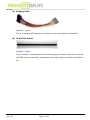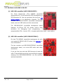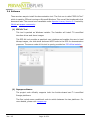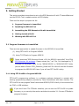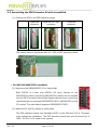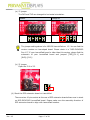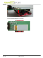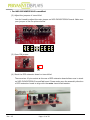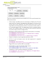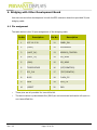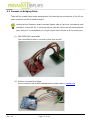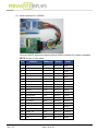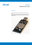
1
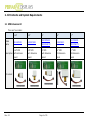
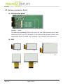
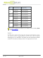
EPD Extension Kit User Manual Date 2015/03/05 Revision 03 龍亭新技股份有限公司 Pervasive Displays, Inc. 4F, No. 28, Chuangye Rd., Tainan Science Park, Tainan City (74144), Taiwan (R.O.C.) Tel: +886-6-279-5399 / Fax: +886-6-505-5300 / http://www.pervasivedisplays.com Rev.: 03 Page: 1 of 30 Index 1. Introduction 3 2. Kit Contents and System Requirements 4 2.1 EPD Extension Kit 4 2.2 Hardware included in the kit 5 2.3 Hardware excluded in the kit 8 2.4 Software 9 3. 4. 5. 2.5 System Requirements 10 Getting Started 11 3.1 Program firmware to LaunchPad 11 3.1.1 Using FET-Pro430 to Program MSP430 11 3.1.2 Using TI CCStudio to Program MSP430 14 3.2 Installing EPD Kit Tool 15 3.3 Assembling the EPD Extension Kit with LaunchPad 16 3.4 Getting started with Kit 20 3.5 Working with EPD Kit Tool 22 Bridging with Other Development Board 26 4.1 Pin assignment 26 4.2 Connect via Bridging Cable 27 Glossary of Acronyms 30 Rev.: 03 Page: 2 of 30 1. Introduction Thank you for purchasing the EPD Extension Kit for low-power electrophoretic paper display (EPD) solutions. This document provides an overview of the Kit and is organized into five main sections: (1) the Kit contents and system requirements, (2) setup and preparation, (3) program firmware, (4) working with the Kit to drive EPD and (5) bridging with other development kit. You will find a glossary of acronyms and references at the end of this document. The EPD Extension Kit consists EPD extension board and 2” (1.44”, 1.9”, 2.6” and 2.7”) EPD. The EPD extension board supports driving Pervasive Displays Inc. (PDI)’s 1.44, 1.9, 2.0, 2.6 and 2.7 inch EPD modules. It has 20 pins socket at the rear side to stack on Texas Instruments (TI)’s LaunchPad board. It also provides a 20 control pins connection with your product or development kit to drive EPD via SPI interface. Rev.: 03 Page: 3 of 30 2. Kit Contents and System Requirements 2.1 EPD Extension Kit There are five models: Model Name 1.44” 1.9” S1144CS021 S1190CS021 1.44” EPD 1.9” EPD 2” EPD 2.6” EPD 2.7” EPD with Extension with Extension with Extension with Extension board board board board Description with Extension board 2” S1200CS021 SG020AS0T2 Kit content Rev.: 03 Page: 4 of 30 2.6” S1260CS021 2.7” S1270CS021 SM027AS0T2 2.2 Hardware included in the kit (1) EPD Extension Board Quantity: 1 piece The board has embedded EPD driving circuit, 40 pins EPD connector, two 10 pins socket and one 20 pins I/O connector. It also features 8M bits flash memory and temperature sensor on board. The 90 degree 20 pin connector will without box. (2) EPD 1.44” 2.0” 2.7” 1.9” Rev.: 03 2.6” Page: 5 of 30 Size PDI Model Name Material Film E1144CS021 Aurora Mb(V231) EK014BS011 Aurora Ma(V230) E1190CS021 Aurora Mb(V231) E1200CS021 Aurora Mb(V231) EG020BS011 Aurora Ma(V230) E1260CS021 Aurora Mb(V231) E1271CS021 Aurora Mb(V231) EM027BS013 Aurora Ma(V230) 1.44” 1.9” 2.0” 2.6” 2.7” For how to recognize the material of your display by the rear labels, please visit this webpage. Quantity: 1 The EPD panel is made by PDI connects with extension board displaying content. User does not need to program different size EPD driver codes to attached development kit (ex. LaunchPad). The packets from the demonstration software contain EPD information and display content in the appropriate size format. Rev.: 03 Page: 6 of 30 (3) Bridging Cable Quantity: 1 piece It’s for measuring EPD signals or bridging to other development kit/product. (4) 40 pins Pin Header Quantity: 1 piece If your product or development kit has female type pin header and want to connect with EPD extension board for development, this male-male pin header is provided in kit. Rev.: 03 Page: 7 of 30 2.3 Hardware excluded in the kit (1) MSP 430 LaunchPad (MSP-EXP430G2553) It’s Texas Instruments (TI)’s MSP430 LaunchPad development kit. To get started with EPD development by EPD Extension Kit, user can purchase this box from TI’s official website or its distribution channels. The box contains one MSP-EXP430G2 LaunchPad development board, one mini-USB cable and other accessories. The MSP-EXP430G2 LaunchPad development board features: 14-/20-pin DIP (N) socket, built-in flash emulation for debugging and programming, 2 programmable LEDs, 1 power LED, 1 programmable button and 1 reset button. (2) MSP 430 LaunchPad (MSP-EXP430F5529LP) It’s also TI’s MSP430 LaunchPad development kit with more powerful MSP430 MCU F5 series. Visit this link for more information. The box contains one MSP-EXP430F5529LP LaunchPad development board, one micro-USB cable and other accessories. If you are first time with this EPD Extension kit and will order TI LaunchPad to work with, we would highly suggest choosing this MSP-EXP430F5529LP, not the previous MSP-EXP430G2553. Rev.: 03 Page: 8 of 30 2.4 Software There are two ways to install the demonstration tool. The first one is called “EDP Kit Tool” which is made by PDI and running on Microsoft Windows. This one will be introduced in this document later. The second one is available under Apache License, Version 2.0 hosted by GitHub at repaper community. (1) EDP Kit Tool This tool is packed as Windows installer. The Installer will install TI LaunchPad interface driver and demo images. This EPD Kit tool provides a graphical user interface and enables the user to load bitmap images, run slide show and send ASCII code to the EPD for demonstration purposes. The source code of this tool is openly provided on PDI official website. (2) Repaper software The project code officially supports both the Arduino-based and Ti LaunchPad Energia platforms. The files include some conditional code to switch between the two platforms. For more details, please visit repaper.org. Rev.: 03 Page: 9 of 30 2.5 System Requirements To use the EPD Kit tool, the following hardware and software elements are required: (1) A computer running Microsoft® Windows® (XP or above). (2) From a hardware standpoint, a Windows® computer with at least one free USB port to connect with the LaunchPad board. Rev.: 03 Page: 10 of 30 3. Getting Started This section provides instructions to set up the EPD Extension Kit with TI LaunchPads and use the EPD Kit Tool to update content on EPD display. There are five steps to prepare the Kit: 1. Program firmware to LaunchPad 2. Installing the EPD Kit Tool 3. Assembling the EPD Extension Kit with LaunchPad 4. Getting started with Kit 5. Working with EPD Kit Tool 3.1 Program firmware to LaunchPad There are two approaches to update firmware to the MSP430 of LaunchPad. (1) Using FET-Pro430 to Program MSP430 (2) Using TI CCStudio to Program MSP430 Please download “EPD Extension Board v2.00 for MSP430 LaunchPad” from PDi’s EPD Extension Kit webpage. Please extract the “.rar” file. It’s developed by TI CCStudio v6.0x project code. In the “MSP430F5529” or “MSP430G2553” folder, you are able to find an “EPD_Extension_Board.out” file. We will need the firmware to program the MSP430 MCU later if you will use FET-Pro430 utinity. 3.1.1 Using FET-Pro430 to Program MSP430 FET-Pro430 programming software is a software package designed to operate with existing programming adapters provided by Texas Instruments and other vendors. The FET-Pro430 Lite can program Texas Instruments MSP430/CC430 family of microcontrollers via JTAG or USB interface. If you don’t have TI’s CCStudio installed, you can use this FET-Pro430 to update firmware, or you can skip this section and direct to section 3.1.2 to use CCStudio to program firmware. Rev.: 03 Page: 11 of 30 Software Installation (1) Download the FET-Pro430 Lite software from Elprotronic. Elprotronic Inc.’s website. It’s free and about 16MB file size. (2) Double click on FET-Pro430 Lite installer. The setup wizard appears automatically. Click to begin the installation process. (3) Once the installation program starts, on-screen instructions will guide you through the remainder of the installation. You must accept license agreement before using software. Startup FET-Pro430 Lite and program firmware (1) Use an USB to mini-USB (or micro-USB) cable that provided in the TI LaunchPad box to connect between computer’s USB Port and LaunchPad’s USB port. USB cable USB port mini-USB port Computer (2) If you have installed the EPD Kit Tool (Section 3.2), the “MSP430 Application UART” driver had installed in your computer and can be found under Ports (COM & LPT) in your Device Manager. (3) To start the FET-Pro430 Lite, click on the Lite/FET-Pro430 Elprotronic icon. The programming dialogue box shows as below: Rev.: 03 Page: 12 of 30 (4) Select the group of Microcontroller Type to - If connecting with MSP-EXP430G2553 LaunchPad, choose “MSP430G2xx” and the second dropdown list to “MSP430G2553”. - If connecting with MSP-EXP430F5529LP LaunchPad, choose “MSP430F5xx” and the second dropdown list to “MSP430F5529”. (5) Click to select the firmware “.out” or “.hex” file to program the LaunchPad. In the Open dialogue, select “TI’s CCE (*.out)” at Files of type and point the file path to select the out file (“EPD_Extension_Board.out”) you will program onto MSP430 MCU. (6) Make sure you have connected well the USB with LaunchPad board. Click to start programming firmware. (7) Please make sure you get the status “Pass” which means the programming process is run successfully. The .out file programming to LaunchPad is for Aurora Mb(V231) type EPD. If your connected EPD is Aurora Ma(V230), you will need TI CCStudio IDE development tool to load our source project code and change parameter in code to work with Aurora Ma(V230) type displays. Rev.: 03 Page: 13 of 30 3.1.2 Using TI CCStudio to Program MSP430 (1) Please get ready the Texas Instruments Code Composer Studio (CCStudio) project code for LaunchPad kit. The default Workspace name is “EPD Extension Board”. We suggest upgrading your CCStudio to version 6.0 above which is also our compiled environment with MSP430 compiler v4.3.5. (2) Start your CCStudio. You will be asked to select a workshop. Please point to the CCStudio workspace folder of this kit and click [OK]. (3) After entering the CCStudio IDE tool, the Project Explorer shows the code structure likes below. (4) Find “#define Gx_Aurora_Mx” in "conf_EPD.h" file under [src] folder. Change to the correct type of EPD you are connecting. The options are G2_Aurora_Ma and G2_Aurora_Mb. Please visit this link to check with the type of your display. (5) To compile the code and download the firmware to the LaunchPad, right click on Rev.: 03 Page: 14 of 30 the project root folder from Project Explorer, on the pop-up menu to select [Build Configurations] / [Set Active] / Select the correct LaunchPad that you are connected. (6) After ensuring the correct LaunchPad model has shown on project name, select from menu [Project] / [Build All (F9)] and wait for building complete and make sure there is no errors in the “Problems” window. (7) Click on the [Debug] button of tool bar or right click on the project to select [Debug As] / [1 Code Composer Debug Session]. (8) A progress information window will pop up and start to download firmware code to the MSP430 MCU of LaunchPad board. Once the download process is done successfully, this window will be closed. The LaunchPad board is now built and tested of the firmware code. You can start debugging the code. Click the Terminate button go back to CCStudio Edit. 3.2 Installing EPD Kit Tool (1) Download the installer of EPD Kit Tool from PDi Extension kit page. The installer name is “EPD Kit Tool v#.# Installer” where # is number for tool version. (2) Double click the installer to start the installation. (3) Follow the instructions on the screen to install the program. The installer will also install the driver (MSP430 Application UART) for the LaunchPad to your computer. (4) If you connect the LaunchPad with computer via USB port now, the Windows® operation system will start to search the driver. You will find the “MSP430 Application UART” or “MSP Application UART” device is installed under Ports (COM & LPT) in your Device Manager. Rev.: 03 Page: 15 of 30 3.3 Assembling the EPD Extension Kit with LaunchPad (1) Connect the EPD to the EPD extension board Open the Slide the FPC into Close the connector connector connector The picture below is connected with a 2” EPD on EPD extension board. For MSP-EXP430G2553 LaunchPad: (2) Make sure the MSP430G2553 IC on LaunchPad Both PDIP14 (14 pins) and PDIP20 (20 pins) devices of the MSP430G2xx Value Line and the MSP430F20xx family can be inserted into the DIP IC socket of LaunchPad. Please make sure you connect the LaunchPad with an inserted MSP430G2553 MCU (M430G2553) to the IC1 socket. The code default supports MSP430G2553 MCU. (3) Adjust the J3 and J5 jumpers of LaunchPad The EPD extension board uses hardware UART, so the RXD and TXD of J3 jumper must change the orientation. The EPD extension board also uses the same pin of LED2. The P1.6 of J5 needs to be opened. Rev.: 03 Page: 16 of 30 (a) J3 jumper The RXD and TXD are changed to horizontal orientation. Default Change to The jumper setting above is for MSP430 LaunchPad rev. 1.5. You can find the version number on Launchpad board. Please check it is “MSP-EXP430G2 Rev.1.5”. If your LaunchPad board is older than this version, please find the schematic of your LaunchPad board and jumped [TXD]-[P1.1] and [RXD]-[P1.2]. (b) J5 jumper Open the P1.6 of J5. (4) Stack the EPD extension board on LaunchPad There are two 10 pins socket at the rear of EPD extension board allows user to stack on MSP-EXP430G2 LaunchPad board. Please make sure the assembly direction of EPD extension board to align with LaunchPad headers. Rev.: 03 Page: 17 of 30 The final installation diagram is as follows. Rev.: 03 Page: 18 of 30 For MSP-EXP430F5529LP LaunchPad: (2) Adjust the jumpers of LaunchPad You don’t need to adjust the main jumper on MSP-EXP430F5529LP board. Make sure your jumper is like the picture below. (3) Open JP8 jumper (4) Stack the EPD extension board on LaunchPad There are two 10 pins socket at the rear of EPD extension board allows user to stack on MSP-EXP430F5529LP LaunchPad board. Please make sure the assembly direction of EPD extension board to align with the outer LaunchPad headers. Rev.: 03 Page: 19 of 30 3.4 Getting started with Kit This section will introduce the EPD Kit Tool and how to update content by this tool. After installing the EPD Kit Tool, the default program directory is located at “C:\Program Files\Pervasive Displays\EPD Kit Tool”. There is some demonstration images at “EPD Kit Tool\images” folder of User’s Documents. (1) Overview of EPD Kit Tool Scan the connected development kit/device Update functions to EPD Detailed communication packets for developer Preview the image will be updated on EPD (2) Connect the kit to your computer USB cable USB Mini-USB Computer Please use the USB cable with the LaunchPad box to connect with the USB port of Rev.: 03 Page: 20 of 30 your computer and the mini-USB/micro-USB port of LaunchPad. (3) Detect the development board Click the [Scan] button to detect the supported connecting development board. or If the TI LaunchPad connects correctly, you will find the Device shows “TI_MSP_EXP430F5529LP(COMxx)” or “TI_MSP_EXP430G2(COMxx)” in the dropdown list. The COM port number should be different from this example. Remember to click [Connect] button to get connection with the LaunchPad. The [Connect] button will be changed to [Disconnect]. You can click on it to disconnect with LaunchPad if you don’t want to work with it later. or After connecting with the LaunchPad, the Detail Log box will show some information likes firmware version and ambient temperature. It means you can start working with this kit set and tool now. (4) Select the correct EPD size Please choose the EPD size that you just connected with the EPD extension board. The size selected must match the EPD size. The dropdown list has 1.44”, 1.9”, 2”, 2.6” and 2.7” items and will show the corresponding resolution. Rev.: 03 Page: 21 of 30 3.5 Working with EPD Kit Tool There are four group functions to update content on EPD with the EPD kit tool. Drawing: to load image immediately; draw line, square, circle by provided coordinate Slideshow: to preload images and set the slideshow effect on or off ASCII: type ASCII code and show the code on EPD without whole image update Others: to load image by defined index; show temperature, firmware version and some control commands (1) Drawing You can click the [Load Image] button to select an image to show on EPD right away. Select the same size image matches the EPD size you just selected by last step. The default pop-up window will point you to the “Images” directory of User Document generated by installer. The resolution information: EPD size Image resolution 1.44” 128 * 96 1.9” 144 * 128 2” 200 * 96 2.6” 232 * 128 2.7” 264 * 196 The preview window will show your selected image and convert it to 1 bit bitmap Rev.: 03 Page: 22 of 30 image format. This image will be sent to EPD immediately. You can also select one of the three types “Line”, “Square” and “Circle”, and give the start and end coordinate to draw image. The X and Y limit the number to the maximum resolution of EPD size. Click [Preview] button to confirm the drawing result. Click [Send] button to send this drawing to EPD. (2) Slideshow The left side area is used for uploading image to flash memory by assigned index. After uploading images, the right side area is used for defining how to play the slideshow effect. Give the index number starts from 0 to 3. This tool allows preloading 4 images to flash memory. Type 0 and click [Load Image] to select an image. The image selected must match the panel size. The same steps to give number and click [Load Image], until 3 if you want to show 4 images continuously. Every time you select an image, the image will be displayed on the EPD. Set the range of numbers you want to apply the slideshow. For example, from 0 to 3rd slide. Give an interval time by seconds between each image. Click [ON] to enable the slideshow effect right away. You can check whether the EPD is to display different image according to the defined time interval. Now, this slideshow function is able to play automatically without the EPD Kit Tool running. You can connect an USB power adaptor with LaunchPad board via USB port. Click [OFF] to disable the slideshow function after connecting the kit and running with the EPD Kit Tool. Rev.: 03 Page: 23 of 30 (3) ASCII Different from sending image to EPD that we just practiced, the ASCII function is to send ASCII code to EPD directly, not sending an image. The ASCII font has built-in kit, so the communication packets could be very short. Click [Load Image] to select an image. Give a coordinate X and Y to have the following content (ASCII code) shows on EPD. For example, when X=30 and Y=0 (pixels) and type “1234567890ABCDE” characters, and then click [Preview]. You will find the string you just typed overwriting on the image at (30, 0) position. Click [Send] button to see the output immediately. The preview area is just for reference, not the actual output effect. It is just a simulation result. The actual output on EPD is without text background transparent effect for the ASCII codes. If you want to remove some characters, try to use space. For example: the first ASCII codes outputs to EPD screen is “Hello World!”. If you want to show “Hello!” and would like to clear the rest of characters after the exclamation mark, you can type “Hello! ” follows 6 spaces after the exclamation mark in the content text box and try to send it on EPD for reviewing. (a) This ASCII function presents partial update on EPD, not global update (full screen update). It is a demonstration only to show how to work with ASCII graphic library in code. (b) If you are connecting AuroraMa(V230) type display, this ASCII will do nothing on display due to V230 display doesn’t support Partial Update in this EPD Kit Tool. (c) For more information or how to implement Partial Update, please visit PDi website for more details. Rev.: 03 Page: 24 of 30 (4) Others The other commands and functions are located here for user to get information from EPD extension board. Custom Image: It’s different from the load image at “Drawing” tab. The load image function at “Drawing” tab updates the image based on a continuous loop memory space to store image data. The Custom Image function here is to store image data by user assigned memory location. You can give the index number (0 to 7) and load image to EPD. The image data will store in assigned memory location. After uploading images, you can type the index number you want and click [Show Image] to show the image directly. EPD Board: to detect whether the EPD extension board stacks on LaunchPad. Reload: to reload the current image that had shown on EPD. F/W Ver: to get the firmware version that had programmed in supported development kit. Rev.: 03 Trigger LED: to turn on/off the LED1 on LaunchPad. Clear All Flash: to clear all of the data in flash memory. Temperature: to get the ambient temperature information. Page: 25 of 30 4. Bridging with Other Development Board User can connect other development kit with the EDP extension board via provided 20 pins bridging cable. 4.1 Pin assignment The table below is the 20 pins assignment of the bridging cable. Pin No. Description Pin No. Description 1 VCC 10-3.3V 11 PANEL_ON 2 (LED1) 12 DISCHARGE 3 (UART_RX) 13 BORDER_CONTROL 4 (UART_TX) 14 SPI_MISO 5 (SW2) 15 SPI_MOSI 6 TEMPERATURE 16 (RST/SBWTDIO) 7 SPI_CLK 17 (TEST/SBWTCK) 8 BUSY 18 FLASH_CS 9 PWM 19 /EPD_CS /RESET 20 GND 10 These pins are all provided for LaunchPad kit. The above values in parentheses like (SW2) are not connected and can be left open on non-LaunchPad kits. Rev.: 03 Page: 26 of 30 4.2 Connect via Bridging Cable There will be a table listed under development kit gives the pin connections of the 20-pin male connector on EPD Extension board. Looking at the Extension board oriented display side up (as front view above) and connector on the left. Pin 1 is the top left pin (the left column are all odd numbered pins) and pin 2 is immediately to its right (right hand column is all the even pins). (1) MSP-EXP430G2 LaunchPad The LaunchPad is able to connect by this type as well. (2) Arduino Leonardo/Uno/Mega How to connect with Arduino-based board, please refer to repaper.org Rev.: 03 Page: 27 of 30 (3) Atmel Xplained Pro (SAM4L) Connect the EPD Extension board to Atmel SAM4L Xplained Pro header marked as EXT3 via the 20 pins cable. Pin 1 Function VCC SAM4L pin VCC Kit pin EXT3_20 2 Rev.: 03 Color Red White 3 - - - Grey 4 - - - Purple 5 - - - Blue 6 Temperature PB03 EXT3_3 Green 7 SPI_CLK PA18 EXT3_18 Yellow 8 BUSY PA06 EXT3_9 Orange 9 PWM PA08 EXT3_7 Brown 10 /RESET PC16 EXT3_6 Black 11 PANEL_ON PA09 EXT3_8 Red 12 DISCHARGE PC15 EXT3_5 White 13 BORDER_CONTROL PB04 EXT3_4 Grey 14 SPI_MISO PA19 EXT3_17 Purple 15 SPI_MOSI PA20 EXT3_16 Blue 16 - - - Green 17 - - - Yellow 18 FLASH_CS PA10 EXT3_10 Orange 19 /EPD_CS PA17 EXT3_15 Brown 20 GND GND EXT3_19 Black Page: 28 of 30 (4) Silicon Labs EFM32 Giant Gecko Starter Kit (EFM32GG-STK3700) Pin Rev.: 03 Function Gecko pin Kit pin Color 1 VCC VCC Exp_20 Red 2 LED1 PC0 Exp_3 White 3 - - - Grey 4 - - - Purple 5 - - - Blue 6 Temperature PD4 Exp_12 Green 7 SPI_CLK PD2 Exp_8 Yellow 8 BUSY PC6 Exp_15 Orange 9 PWM PD3 Exp_10 Brown 10 /RESET PD5 Exp_14 Black 11 PANEL_ON PD6 Exp_16 Red 12 DISCHARGE PD7 Exp_17 White 13 BORDER_CONTROL PB12 Exp_13 Grey 14 SPI_MISO PD1 Exp_6 Purple 15 SPI_MOSI PD0 Exp_4 Blue 16 - - - Green 17 - - - Yellow 18 FLASH_CS PB11 Exp_11 Orange 19 /EPD_CS PC5 Exp_9 Brown 20 GND GND Exp_1 Black Page: 29 of 30 5. Glossary of Acronyms CCS, CCStudio Texas Instruments’ Code Composer StudioTM IDE development tool MCU Microcontroller unit PDI/PDi Pervasive Displays, Inc. TI Texas Instruments Corporation EPD Electrophoretic paper display Rev.: 03 Page: 30 of 30