1
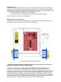
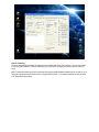
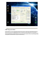
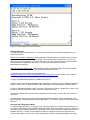
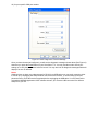
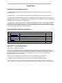
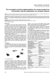
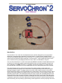
U.S. Water Rockets’
User Manual
Introduction:
The ServoChron™ 2 is a low cost time delayed dual servo controller designed for use as a parachute
deployment or staging actuator mechanism for Water Rockets, or Water Rocket Propelled Vehicles.
There are other potential applications for the ServoChron™ 2 , but this document primarily focuses on the
Water Rocket dual parachute deploy application. The ServoChron™ 2 was created specifically to make
servo controlled recovery and staging mechanisms easy to build, and affordable for everyone.
The core of the ServoChron™ 2 is the Texas Instruments MSP430 LaunchPad. This $4.30US board is an
inexpensive microcontroller hobbyist experimenting platform that you program application firmware into
with a USB cable. The FREE ServoChron™ 2 application firmware file created by U.S. Water Rockets
turns the MSP430 LaunchPad into a user programmable dual servo deployment system timer/controller.
The custom firmware acts as a timer and servomotor driver which monitors a trigger switch and
individually actuates two separate servo motors when a preconfigured delay time for each has elapsed
following the trigger condition. The trigger switch is most often used to detect the launch of the Water
Rocket and the timer delay is set to the predicted time to reach apogee. One servomotor usually is used to
deploy a small drogue parachute at apogee, and the second servo motor is used to deploy a larger main
parachute some time later. This arrangement allows the rocket to quickly but controllably descend on the
drogue parachute closer to the ground, where the larger parachute takes over and slows the final portion
of descent to a rate which minimizes the chance of damage to the rocket upon landing. This arrangement
is designed to prevent the rocket from drifting far from the launch area due to winds by reducing the time
spend descending, but still providing a gentle landing. Another application commonly requiring dual servos
is to deploy two independent parachute systems at apogee for redundancy. There are limitless
applications to explore.
The ServoChron™ 2 was designed and tested by the renowned U.S. Water Rockets, which have been
featured on internationally broadcast programs like MythBusters. ServoChron™ 2 is the result of many
years of experience in setting Water Rocket World Records as well as recreational and scientific Water
Rocket experiments.
ServoChron™ 2 Features:
•
•
•
•
•
•
•
•
•
•
•
•
•
•
•
Dual servo control
Built on ultra-affordable MSP430 LaunchPad Platform ($4.30)
Operates on 3.7V-6.0V DC. You may use various power sources notably a single
lightweight Lithium Polymer rechargeable cell.
User defined servo positions for each servo
User programmable delay for each servo from 0.000 to 30.000 seconds in 1 millisecond
increments
USB Firmware update (with included cable! No special programming hardware to buy!)
Edge sensitive trigger input with automatic polarity detect
Trigger input capable of sensing contact open or close events shorter than 10
nanoseconds
Innovative 2-button operator interface with easy to remember setup
3 Status LEDs
UART (Serial) diagnostics mode
Dimensions: 2.0 x 2.6 inches (50.80 x 66.04 mm)
Weight : 0.635 oz (18 grams)
Includes testing and arming operational modes
Fully RoHS compliant. Contains legal levels of lead and hazardous materials
Purchasing information:
The ServoChron™ 2 costs NOTHING including FREE Download.
You will need to purchase your own MSP430 LaunchPad board, servos, and battery. See the assembly
section for full parts list and prices. The total Bill of Materials for a complete dual deploy system,
assembled, and ready to fly will be approximately $12.90US.
ServoChron™ 2 Controls:
All configuring of the user parameters is done using the custom designed Operator Interface of the
ServoChron™ 2. The interface controls consist of two pushbuttons and 3 LEDs.
The pushbuttons are defined as follows:
• S1 = Reset (Right) – This button will reset the ServoChron™ 2 and is used to set up the delay
timers.
• S2 = Mode (Left) – This button is used to change modes and set up all configuration parameters.
The LEDs are defined as follows:
• Power – This green USB near the USB connector LED illuminates whenever power is applied to
the ServoChron™ 2
• Red = Servo ‘A” Status indicator – This LED is used to configure Servo 'A'
• Green = Servo ‘B’ Status indicator – This LED is used to configure Servo 'B'
Figure 1: The Operator Interface
Configuration Modes:
The ServoChron™ 2 has two configuration modes which must be set up prior to first use. Once
configured, the settings are stored in nonvolatile memory and will be remembered each time you power up
or reset the ServoChron™ 2, or until you choose to modify the settings. The operator interface was
designed to maximize ease of use, and eliminate the need for any special tools, cables, cheat-sheets,
software, or even a computer. The ServoChron™ 2 configuration modes are:
•
Servo Positioning Definition Mode: This mode is used to define where the servomotor “home”
and “deployed” positions are. Follow these steps to configure the two positions:
1. Hold down the Mode button while connecting power to the ServoChron™ 2. The Red LED
will light steadily to indicate the Servo ‘A’ home position is being set.
2. Tap the Mode button to change the “home” position in 30 degree increments until you
reach the desired angle.
3. Press and Hold the Mode button for longer than 1 second to save the “home” position.
The Red LED will now go dark, and Servo ‘A’ will move into the "deployed" position.
Configure the “deployed” position the same way as described for the “home” position.
4. The Green LED will low illuminate indicating that you are now configuring the “home”
position of Servo ‘B’. The positions for Servo ‘B’ are configured the same was as they are
for Servo ‘A’. Set both positions for Servo ‘B’ now.
•
Delay Timer Setting Mode: This mode is used to program the delay time from trigger until each
servo activation event. Follow these steps to configure the delay:
1. Press and hold the Mode Button in and tap the Reset Button
2. Continue to hold in the Mode button, and release it when the delay time for Servo ‘A’ has
elapsed.
3. Wait additional time and then tap the Mode button to set the Servo ‘B’ delay time when
the desired delay has elapsed. The LEDs for each servo will flash at 1 second intervals to
assist in timing the delays.
Operation Modes:
•
Standby Operating Mode: This mode is entered by default as power up. When this mode is active,
the servo will move to the “home” position and The Red and Green LEDs will display a blinking
pattern to remind you what the delay timer settings are. The pattern is one flash per second blink
rate for the duration of each timer delay, followed by a two second pause with both LEDs on. This
blinking pattern repeats forever. When this mode is activated, the state of the launch detect
switch is read constantly and any change is detected. When a change is sensed, the triggered
mode is activated.
Note: short delay times will result in a very small period of the LED “Off” off between 2 second
pauses.
•
Triggered Mode: When triggered mode is activated, the status LEDs will begin to rapidly blink as
the timer delays are counting down. When each timer delay has elapsed, the associated servo will
move to the Deployed Position and once both servos have been actuated, the ServoChron™ 2
will go into Deployed Mode.
•
Deployed mode is the final mode after the ServoChron™ 2 has actuated both servos. In this
mode, both LEDs will blink once every 4 seconds to indicate the deployed mode is active. Both
servos will be held in the "deployed" position for 2 minutes and then the servo outputs will be
deactivated to conserve battery power. You must press the Reset Button or cycle power to exit
this mode.
•
Test/Arming Mode: This mode is available when the ServoChron™ 2 is in Standby Operating
Mode and the Mode Button is pressed and held in. When this condition is detected, the servos will
be forced to move to their "deployed" positions. You can use this to test your deploy systems, or
you can use this mode to arm your deploy mechanisms if you have designed them with a positive
latch. When the Mode button is released, the ServoChron™ 2 automatically goes back into to
Standby Operating Mode.
Error Codes:
The Red LED indicates all error conditions by turning on steadily and briefly flashing OFF a number of
times in a repeating cycle. The number of OFF flashes will reveal the error code. The possible error codes
are:
•
•
2 Flashes = Time Configuration Error
3 Flashes = Servo Configuration Error
Troubleshooting:
Symptom:
I get a Time
Configuration Error
I get a Servo
Configuration Error.
Possible causes:
You have set one or both
time delay for longer than 30
seconds
You are powering up for the
first time after loading
firmware.
You have set the “Home”
and “Deployed” positions of
one or more servos to the
same location.
You are powering up for the
first time after loading
firmware.
Corrective Action:
Reconfigure the delay times and be sure
to set them both to values less than 30
seconds.
Reprogram the servo positions and be
sure that each servo has different
locations for each of the two positions.
ServoChron™ 2 Theory of Operation:
•
In normal use, the ServoChron™ 2 powers up and directs the servomotors to move to their
"home" positions.
•
ServoChron™ 2 monitors the trigger input for a state change. In a typical Water Rocket this could
be an acceleration or vibration switch or a simple pushbutton held depressed by the launcher.
When the Water Rocket is launched, the trigger condition is detected.
•
ServoChron™ 2 begins timing for the preconfigured interval calculated to approximate the time to
apogee. When the Servo ‘A’ time interval has elapsed, the rocket would be at apogee, and
ServoChron™ 2 directs the Servo ‘A’ to move to the "deployed" position. The mechanical motion
of the servomotor is now used to release a drogue parachute. Later, when the Servo ‘B’ interval
has elapsed, the rocket will have descended for a while, and ServoChron™ 2 directs t Servo ‘B’ to
move to the "deployed" position, releasing the larger main parachute.
Assembly Instructions:
Tools Required:
• Wire Cutter / Stripper
• Soldering Iron
• Solder
Recommended Parts List:
To assemble a complete ServoChron™ 2 Dual Deploy System, a number of components are needed. The
design has been thoroughly tested using the components listed below. Where noted, you may be able to
locate equivalent replacement components which could suit your specific application.
• 1x MSP-EXP430G2 - MSP430 LaunchPad Value Line Development kit
• 1x MULTICOMP - R13-509A-05-BR - SWITCH, PUSHBUTTON, SPST, 3A, 250V (Or equivalent)
• 1x Turnigy 160mAh 1S 130C Lithium Polymer Cell (Or Equivalent)
• 12 inches of #22 Gauge Wire
• 2x HXT900 9g / 1.6kg / .12sec Micro Servo (Or equivalent)
Optional Parts List:
In addition to the components listed above, we chose to add the components listed below to the design.
These components are merely extension leads for the battery and servo which allow the components to
be plugged and unplugged easily, resulting in a modular design. If you omit these extension leads, you will
need to solder the components together permanently using #22 gauge wire.
• Mini Plug Extension for Micro Battery 10cm (5pcs/bag)
• JR-Type Servo Extension 10CM Servo Lead (JR) 32AWG Ultra Light (10pcs/bag)
Note: See Appendix A for a complete Bill of Materials
MSP430 LaunchPad Wiring Diagram:
There are only 10 connections which must be made to the MSP430 LaunchPad Evaluation Kit Printed
Circuit Board. These connections are illustrated in the diagram below.
Figure 3. MSP430 LaunchPad Wiring Diagram
MSP430 LaunchPad Firmware Programming:
The core of the ServoChron™ 2 Deploy System is the MSP430G2231 microcontroller from Texas
instruments. This microcontroller contains flash memory which must be programmed with the
ServoChron™ 2 firmware to create the deploy system. Texas Instruments has created a very low cost
evaluation board which contains all the circuitry needed to program the MSP430G2231, which is used as
the main board for the ServoChron™ 2. Once you have connected the battery, servo, and launch detect
switch to the MSP430 LaunchPad, the only step which remains is to download the firmware into the
microcontroller. There are several ways to download the firmware, but this document references a FREE
stand alone application which can download the firmware file with a single mouse click. This manual
section details where to obtain the software and how it is used to download firmware.
Hardware Required:
• MSP430 LaunchPad Evaluation Kit
• PC with Windows XP or later Operating System
Software Required:
• Elprotronics FET-Pro430 Lite (from elprotronics.com)
• Firmware Project File (from USWaterRockets.com)
Step 1: Download the Programming Software Tool
Go to the website http://www.elprotronics.com/download.html and download the free program called “FETPro430 Lite”. When the download has completed, read the installation instructions and follow the
procedures for installing the software and the USB drivers included.
Figure 4. FET-Pro430 Lite Download
Step 2: Run the FET-Pro430 Lite Software
Find the programming tool icon on your desktop or in the program start menu of your PC and execute the
application. Note: please make sure that you have followed all the USB driver installation instructions
before running the application or connecting the USB cable to the MSP430 LaunchPad.
Figure 5. FET-Pro430 Lite Dialog
Step 3: Load the firmware project file into the programming application
Go to the “File” menu of the FET-Pro430 Lite application and click on “Open Project”. You will then be
presented with a file open dialog with which you will navigate to the directory where the firmware project
file is stored. You select the firmware you wish to load and click “Open”. The project file will then load into
the programming application.
Figure 6. FET-Pro430 Lite Project File Open
Step 4: Program the Microcontroller
Disconnect any batteries from the ServoChron™ 2 and connect a USB cable from your PC to the USB
port. Warning: You must NEVER connect the battery and the USB cable at the same time. You can
damage your PC or the ServoChron™ 2, or cause the battery to explode. Once you have connected
the USB cable you can press the “AUTO PROG.” button to load the firmware file. The programming tool
will report “PASS” when the operation is complete.
Figure 7. FET-Pro430 Lite Auto Program
Step 5: Finishing
Close the programming software and disconnect the USB cable from your computer. You are now ready
to use your ServoChron™ 2. Before launching, you will need to configure the servo positions and time
delay
Note: Please save these instructions and keep the programming software installed and up to date on your
computer, because this tool will be used to program ServoChron™ 2 Firmware Updates as well as future
U.S. Water Rockets projects.
Figure 8. FET-Pro430 Lite Successful Programming
UART Diagnostics Mode:
The ServoChron™ 2 can communicate directly with a personal computer using the MSP430 Application
UART which is built into the MSP430 LaunchPad. This feature provides USB to RS-232 conversion
hardware connected to the MSP430G2231 microcontroller which communicates over a backchannel link
over the USB debugger interface. With this mode, you can get a readout of all the current settings as well
as diagnostic error codes which may help in troubleshooting.
Figure 10. UART Diagnostics Terminal Output
Software Required:
To enable the UART Debug Interface, you may need to install one or two software packages on your
Windows based PC:
Serial Terminal Software Application: Most installations of Windows prior to Vista will include a terminal
application as part of the basic windows package. This is usually called "Hyterterminal". If you do not
already have a terminal program on your PC, there are many open source terminal programs available.
We recommend an application called Tera Term, which you can download from here:
http://ttssh2.sourceforge.jp
MSP430 Application UART Driver: This software is needed to enable the USB to Serial Port Converter
hardware built into the MSP430. To install the MSP430 Application UART:
1) Download the driver software from the following link:
http://www.uswaterrockets.com/shared/MSP430_LaunchPad_Drivers.zip and extract it into a folder on
your PC.
2) Plug in your MSP430 LaunchPad to a USB port on your PC.
3) Open "Control Panel>System>Hardware>Device Manager" and find the entry for "MSP430 Application
UART" in either "Ports" or "USB Controllers" (the exact location varies depending on windows version)
4) Click on "MSP430 Application UART" and under "Drivers" there will be an "Update Driver" option. Click
this button and select the option to load a driver from a specific location.
5) Select the location where you saved the extracted drivers from step 1, and click OK. The drivers will
now install.
6) A port name/number will be assigned to the MSP430 Application UART and will be displayed in the
Device Manager. It would typically be called COMx (where 'x' is a number). Write this value down for later
reference.
Using the UART Diagnostics Mode:
To use the Diagnostic UART you must open your Terminal Program and set the communications port to
the "COMx" value assigned to the MSP430 Application UART (from Step 6 above). When you select that
port as the terminal communications port, you will also neet to set the parameters that the ServoChron™ 2
firmware requires. To do this, find the dialog box where you configure the serial port properties and
configure the settings. You will need to open the dialog and configure the following settings (see Figure
10) for your specific COM port number:
Figure 10. UART Diagnostics Terminal Settings
Once you have the terminal configured, you will see the diagnostic messages shown above (See Figure 9)
whenever you press the Reset Button on your ServoChron™ 2. You may use this mode to check your
settings or to verify they are correct before a launch. You may also look for diagnostic messages which will
display if an error is detected.
Notes:
Windows does not have very robust support for RS-232 over USB and so you can easily cause the driver
to freeze up by unplugging the USB port while connected to the terminal. To avoid locking up the port,
please be sure to close the terminal completely before unplugging the USB cable. You may also have to
re-install the MSP430 Application UART software drivers if you move the USB connection to a different
USB port on your PC.
Appendices
Appendix A: System Requirements:
1) Texas Instruments MSP430 LaunchPad Evaluation Kit. This $4.30 circuit board is the core of the
ServoChron™ 2.
2) Power Source – 3.7V to 6.0V battery. Confirm that it has sufficient current to power two servos.
3) Servo Motors – We recommend a micro servo designed for use with a single LiPo cell. These servos
are optimized for use with a 3.7V battery. Older servos designed for 5V systems may work but will require
additional cells (more weight), and modified wiring.
4) Trigger switch – This can be an off the shelf switch mounted to the rocket in such a way as to change
state when the rocket leaves the ground, or something even simpler such as a bit of wire affixed to the
ground that is loosely connected between the two connections for the trigger switch so that the connection
is broken when the rocket lifts off and starts the timer..
Appendix B: Bill Of Materials (Dual Servo)
Suggested Parts
Qty Part
1 MSP-EXP430G2
1 R13-509A-05-BR
1 T1601S-30
1 HK9727
2 HK9710
2 HXT900
Description
MSP430 LaunchPad Value Line Development kit)
SWITCH, PUSHBUTTON, SPST, 3A, 250V
Turnigy 160mAh 1S 130C Lithium Polymer Cell
Mini Plug Extension for Micro Battery 10cm
JR-Type Servo Extension 10CM Servo Lead
HXT900 9g / 1.6kg / .12sec Micro Servo
Total Price:
Price ea.
$4.30US
$0.95US
$1.47US
$0.40US
$0.20US
$2.69US
$12.90US
Appendix C: Licensing Agreement
SERVOCHRON 2 LICENSING AGREEMENT
The files and documentation for ServoChron™ and variants thereof are provided free to use and distribute without modification in
any way. You may distribute them freely but are prohibited from manufacturing or distributing products or media containing or
derived from the ServoChron™ project without express written consent from U.S. Water Rockets. Any distribution or use of the
ServoChron™ project must give proper attribution to U.S. Water Rockets, and a link to the U.S. Water Rockets website
(www.USWaterRockets.com) must be included.
Please contact U.S. Water Rockets to obtain permission if you wish to create ServoChron™ based products.
ServoChron, and the ServoChron Logos are ™ and © 2011-2012 U.S. Water Rockets All rights reserved.
U.S. Water Rockets, and U.S. Water Rockets Logo are ™ and © 2011 U.S. Water Rockets All rights reserved.
Notice: The information contained in this project is provided "AS IS" without warranty, express or implied. U.S. Water Rockets
makes no warranty as to the reliability, accuracy, timeliness, usefulness, adequacy, completeness or suitability of the information.