1
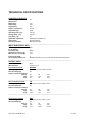
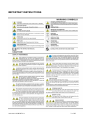
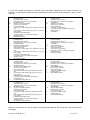
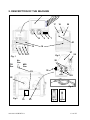
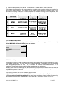
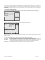
USER MANUAL TM 236 PULSE SYNERGIC/GEN 910.100.335GB REV01 1 of 44 Fimer SpA Via Brigatti, 59 20050 RONCO BRIANTINO (MILAN) Italy Tel. +39 0396079326 Fax. +39 0396079334 www.fimer.com [email protected] 910.100.335GB REV01 2 of 44 USER AND MAINTENANCE MANUAL Firmer S.p.A. would like to thank you for choosing this welding machine: if used according to the instructions reported in this user and maintenance manual, it will accompany you in your work for many years without any problem. The manual is an integral part of the equipment and must always accompany the machine each time it is moved or resold. The user is responsible for making sure the machine is complete and in good working order. Fimer S.p.A. has the right to make changes at any time and without notice. The rights of translation, reproduction and adaptation, in whole or in part and with any means (including scanned documents, copies, film and microfilm) are reserved and prohibited without Fimer’s written authorisation. TABLE OF CONTENTS DECLARATION OF CONFORMITY ............................................................................................................. 4 NOMINAL DATA ............................................................................................................................................ 5 TECHNICAL SPECIFICATIONS.................................................................................................................... 6 IMPORTANT INSTRUCTIONS ...................................................................................................................... 7 1. GENERAL FEATURES AND NOTES ON CONSULTING THE MANUAL ......................................... 10 2. DESCRIPTION OF THE MACHINE......................................................................................................... 12 3. DESCRIPTION OF THE VARIOUS TYPES OF WELDING................................................................... 15 3.1 MIG/MAG WELDING............................................................................................................15 3.1.1 MANUAL SHORT-ARC MIG WELDING .....................................................................16 3.1.2. SYNERGIC SHORT ARC MIG WELDING..................................................................18 3.1.3 MANUAL PULSED MIG WELDING.............................................................................20 3.1.4 SYNERGIC PULSED MIG WELDING ..........................................................................21 3.2 TIG WELDING .......................................................................................................................24 3.2.1TRADITIONAL TIG WELDING .....................................................................................25 3.2.2 PULSED TIG WELDING ................................................................................................26 3.3 MMA WELDING ....................................................................................................................27 3.3.1 MANUAL MMA WELDING ..........................................................................................28 3.3.2 SYNERGIC MMA WELDING ........................................................................................29 4. POWER SUPPLY CONNECTION ............................................................................................................ 30 5. OUTPUT CONNECTIONS ........................................................................................................................ 30 5.1 CONNECTION FOR MIG WELDING WITH TRADITIONAL TORCH ............................30 5.2 CONNECTION FOR MIG WELDING WITH SPOOL OR PUSH-PULL TORCH..............30 5.3 CONNECTION FOR TIG WELDING ...................................................................................31 5.4 CONNECTION FOR MMA WELDING ................................................................................31 6. INSTALLATION OF THE WELDING WIRE .......................................................................................... 32 7. CONNECTION OF THE GAS CYLINDER AND REGULATOR ........................................................... 33 8. WELDING PROCESSES ........................................................................................................................... 35 8.1 Manual MIG welding...............................................................................................................35 8.2 Synergic MIG welding.............................................................................................................36 8.3 MMA WELDING ....................................................................................................................37 8.4 TIG WELDING .......................................................................................................................38 9. REPLACEMENT OF SHEATH INSIDE THE TORCH CABLE.............................................................. 39 10. REMOTE CONNECTION........................................................................................................................ 40 11.1 MIG WELDING WITH STANDARD TORCH ...................................................................40 11.2 MIG WELDING WITH SPOOL OR PUSH-PULL TORCH ...............................................40 11.3 TIG WELDING .....................................................................................................................40 11.4 MMA WELDING ..................................................................................................................40 11. TROUBLESHOOTING ............................................................................................................................ 41 12. BLOCK DIAGRAM ................................................................................................................................. 42 13. MEMORISATION OF THE WORKING POINT .................................................................................... 42 910.100.335GB REV01 3 of 44 DECLARATION OF CONFORMITY 910.100.335GB REV01 4 of 44 NOMINAL DATA 910.100.335GB REV01 5 of 44 TECHNICAL SPECIFICATIONS CONSTRUCTION DATA WEIGHT [Kg]: Dimensions: Width [mm]: Depth [mm]: Height [mm]: 23 Degree of protection: IP 21S Height ASL [m]: 1000 Operating temp. [°C]: -10/+40 Storage temp. [°C]: -20/+55 Test temp. [°C]: 40 270 560 480 Applicable regulations: EN.60974-1 EN.60974-10 Group/class: Group 2 Class A Thermal protection: Built-in thermostat ______________________________________________________________________________________________ INPUT ELECTRICAL DATA: Line voltage: No. of phases: Frequency [Hz]: Effective line current [A]: Maximum line current [A]: 230 1 50/60 21.6 40.3 Input power [kVA]: Power supply protections: 5 Delayed 25A fuses or Co K Curve 25A magneto-thermal switches ____________________________________________________________________________________________ OUTPUT DATA: Static Characteristics: Wire diameter: Drop 0.6-0.8-1.0-1.2 First welding method: Welding range: No-load voltage [V]: MIG/MAG from 15A / 14.75V to 235A / 25.75V 55 Output currents and voltages: Duty [%]: I2 [A]: U2 [V]: 35 220 25 60 160 22 100 130 20.5 ______________________________________________________________________________________________ Second welding method: TIG Welding range: No-load voltage [V]: from 15A / 10.6V to 235A / 19.4V 55 Output currents and voltages: Duty [%]: 35 60 100 I2 [A]: 220 160 130 U2 [V]: 18.8 16.4 15.2 ____________________________________________________________________________________________ Third welding method: Welding range: No-load voltage [V]: Duty [%]: I2 [A]: U2 [V]: 910.100.335GB REV01 MMA from 15A / 10.6V to 185A / 17.4V 55 35 60 100 185 138 109 27.4 25.52 24.36 6 of 44 IMPORTANT INSTRUCTIONS 910.100.335GB REV01 7 of 44 910.100.335GB REV01 8 of 44 910.100.335GB REV01 9 of 44 1. GENERAL FEATURES AND NOTES ON CONSULTING THE MANUAL The TM236 welding machines use INVERTER technology. They are extremely compact and versatile machines that can be used in all situations where high performances must be achieved in a limited amount of space. These welders are for Synergic MIG/MAG (Short-Arc and Pulsed), conventional MIG/MAG (Short-Arc and Pulsed), TIG and MMA (Synergic and conventional) welding. The innovative interface system allows a simple and intuitive use of the machine with the possibility to personalise nearly every welding parameter. All the main parameters of the machine are stored on a special memory card (SD-Card); in this way, your machine will always be up-to-date with the most recent developments in the welding field (e.g. synergic curves for new materials, etc.). The removal of the memory card prevents the machine from operating, which therefore makes it an effective antitheft system and protection device against improper use. The wire spool of 300 mm necessary for MIG welding is lodged internally. The advanced control techniques adopted allow reaching quality results that until today were only reserved to much larger and more expensive machines, while maintaining a very high level of reliability and ease of use. This machine allows executing the following types of welding: MIG Welding: short-arc, manual MIG Welding: pulsed, manual MIG Welding: short-arc, synergic MIG Welding: pulsed, synergic TIG Welding: Lift-Arc TIG Welding: Lift-arc, pulsed MMA Welding: Manual MMA Welding: Synergic A traditional and push-pull or spool torch can also be used for MIG welding. This user manual contains in-depth information on the adjustments and operating modes of the machine: its complete reading will allow you to appreciate its extreme flexibility and practicality of use. Please note that the figures most frequently referred to (figures 1 to 4) are grouped together on page 12. 910.100.335GB REV01 10 of 44 If you do not consider it necessary to read the manual completely, depending on the type of welding to be executed, we recommend reading at least the following sections (as well as the warnings on page 6 of this manual): MIG Welding: short-arc, manual TIG Welding 1. 2. 3. 3.1. 3.1.1. 4. 5. 5.1 1. 2. 3. 3.2 3.2.1 4. 5. 5.3 7. 8. 8.4 5.2 6. 7. 8. 8.1 General features Description of the machine Description of the various types of welding MIG/MAG welding Manual short-arc MIG welding Power supply connection Output connections Connection for MIG welding with traditional torch and gas Connection for MIG welding with Spool or Push-pull torch and gas Installation of the welding wire Connection of the gas cylinder and regulator Welding process Manual MIG welding General features Description of the machine Description of the various types of welding TIG Welding Traditional TIG welding Power supply connection Output connections Connection for TIG welding Connection of the gas cylinder and regulator Welding process TIG Welding MIG Welding: pulsed, manual Pulsed TIG welding 1. 2. 3. 3.1 3.1.3 4. 5. 5.1 1. 2. 3. 3.2 3.2.2 4. 5. 5.3 7. 8. 8.4 5.2 6. 7. 8. 8.1 General features Description of the machine Description of the various types of welding MIG/MAG welding Manual pulsed MIG welding Power supply connection Output connections Connection for MIG welding with traditional torch and gas Connection for MIG welding with Spool or Push-pull torch and gas Installation of the welding wire Connection of the gas cylinder and regulator Welding process Manual MIG welding General features Description of the machine Description of the various types of welding TIG Welding Pulsed TIG welding Power supply connection Output connections Connection for TIG welding Connection of the gas cylinder and regulator Welding process Pulsed TIG welding MIG Welding: short-arc, synergic Manual MMA welding 1. 2. 3. 3.1. 3.1.2 4. 5. 5.1 1. 2. 3. 3.3 3.3.1 4. 5. 5.4 8. 8.3 5.2 6. 7. 8. 8.2 General features Description of the machine Description of the various types of welding MIG/MAG welding Synergic short-arc MIG welding Power supply connection Output connections Connection for MIG welding with traditional torch and gas Connection for MIG welding with Spool or Push-pull torch and gas Installation of the welding wire Connection of the gas cylinder and regulator Welding process Synergic MIG welding with gas General features Description of the machine Description of the various types of welding MMA Welding Manual MMA welding Power supply connection Output connections Connection for MMA welding Welding process Manual MMA welding MIG Welding: pulsed, synergic Synergic MMA welding 1. 2. 3. 3.1. 3.1.4 4. 5. 5.1 1. 2. 3. 3. 3.3.2 4. 5. 5.4 8. 8.3. 5.2 6. 7. 8. 8.2 General features Description of the machine Description of the various types of welding MIG/MAG welding Synergic, pulsed MIG welding Power supply connection Output connections Connection for MIG welding with traditional torch and gas Connection for MIG welding with Spool or Push-pull torch and gas Installation of the welding wire Connection of the gas cylinder and regulator Welding process Synergic MIG welding with gas General features Description of the machine Description of the various types of welding MMA Welding Synergic MMA welding Power supply connection Output connections Connection for MMA welding Welding process Synergic MMA welding Attention: The machine can only be used for the purposes described in this manual and must not be used to thaw pipes. 910.100.335GB REV01 11 of 44 2. DESCRIPTION OF THE MACHINE 1 23456 17 9 10 18 20 8 7 21 - + 15 16 27 12 13 14 11 Fig. 1 No Gas TIG Gas 26 Fig.2 28 MIG Gas 23 30 29 22 Fig.4 Fig.3 19 910.100.335GB REV01 25 Fig.4A Fig.4B 12 of 44 FIGURE 1: 1. Graphic display: The display shows different screens depending on whether the machine is in welding mode or setting mode. In welding mode, the display is divided into five main parts: Part 1 Pronto a saldare > 150 26.0 A INIZIO INDIETRO MEM+ Buttons V Adjustable value Part 3 Arc force Hot start 20% 20% T hot start 0.5s Highlighted value Part 5 MMA Manuale Part 2 Part 4 Part 1: State of the machine Part 2: Meaning of the active buttons (buttons 2, 3, 4, 5 of fig. 1) Part 3: Value of the measurements set Part 4: Type of welding Part 5: Indicates the values set for the various welding parameters (to change the set value, highlight the value with knob 10 and press to confirm; the value is highlighted as a negative. Change the value by turning the knob and confirm the new value by pressing knob 10 again). Adjustable value: Indicates the welding parameter that can be changed with knob 9. Highlighted value: Indicates the welding parameter that is being changed with knob 10. During the setting mode, the display shows different screens according to the value being set at that moment (see the following sections relating to the various welding methods). The display also shows: - At start-up, the Fimer logo and the Firmware revision are displayed. 2. 3. 4. 5. 6. 7. 8. 9. Command button: Its meaning is reported in the first line of Part 2 of the display; normally, the pressing of this button returns to the main screen. Command button: Its meaning is reported in the second line of Part 2 of the display; normally, the pressing of this button returns to the previous screen. Command button: Its meaning is reported in the third line of Part 2 of the display; when this button is pressed, it memorises the current machine settings (up to a maximum of 32). Command button: Its meaning is reported in the fourth line of Part 2 of the display; this button allows the gas to flow without the need to press the torch button. Wire feed button: When active, the wire (MIG) can be advanced. SD slot: This slot, covered by a special plastic cover, must contain the SD-Card supplied with the machine; without this card, the machine remains inactive and a special signal is reported on the display. USB port: only for technical assistance. Knob for setting the main welding parameter: the main welding parameter can be set with this knob: MMA Welding: sets the welding current. TIG Welding: sets the welding current. Manual MIG welding: sets the welding voltage. Synergic MIG welding: sets the thickness of the piece to be welded. 910.100.335GB REV01 13 of 44 10. 11. 12. 13. 14. 15. 16. Knob for setting the other welding parameters: The remaining welding parameters can be set with this knob; turn the knob to select the parameter and press to confirm, turn the knob again to change the set value and press again to confirm the new value. “+” front inlet: MMA Mode: Electrode holder TIG Mode: Ground clamp MIG Mode with gas: Not used MIG Mode without gas: Ground clamp “-” front inlet: MMA Mode: Ground clamp TIG Mode: TIG torch MIG Mode with gas: Ground clamp MIG Mode without gas: Not used Remote connector: This connector allows using the following types of torches: MIG torch (GAN Spool) MIG torch (Push-Pull) TIG torch GAS outlet: MMA Mode: inactive (internal tap positioned on NO GAS) MIG Mode with gas: inactive (internal tap positioned on MIG GAS) MIG Mode without gas: inactive (internal tap positioned on NO GAS) TIG Mode: Gas connection to the welding torch (Internal tap positioned on TIG GAS) Euroconnector: quick connector for welding torch. This connector is used to supply welding gas to the torch, the electrical contacts of the torch button and the welding current. Air grills FIGURE 2: 16. 17. 18. 20. 21. Air grills ON-OFF switch: turns the machine on and off. Input cable: connection cable to the mains power equipped with plug. Connector for supplying power to the liquid cooling system (Optional): Warning: the connector contains dangerous voltages: NEVER use it for purposes other than those for which it was specifically designed. Welding gas inlet MMA Mode: Not used TIG Mode: GAS connection to the cylinder MIG Mode with gas: GAS connection to the cylinder MIG Mode without gas: Not used FIGURE 3: 19. 22. 23. 25. 26. 27. 28. 29. 30. Nominal data Wire spool Gas tap: The gas tap has three positions MIG GAS Position: sends welding gas coming from connection 21 of the cylinder to the Euroconnector (use this position for MIG welding with gas) NO GAS Position: interrupts the gas flow (use this position for MMA welding and MIG welding without gas) TIG GAS Position: sends welding gas coming from connection 21 of the cylinder to inlet 14 location on the front (use this position for TIG welding) Wire Feeder Wire pressure regulators: allow regulating the tension of the welding wire. Wire-feeder motor Upper wire feed rollers Lower wire feed rollers Wire inlet of the wire feeder motor 910.100.335GB REV01 14 of 44 3. DESCRIPTION OF THE VARIOUS TYPES OF WELDING This chapter briefly describes the various welding methods and the main settings that need to be set in order to execute them. The reading of this chapter is not sufficient for knowing how to use the machine correctly. Therefore, it is also important to read the following sections (especially, the chapters regarding the methods for connecting the torches and ground cables). N WELDING PROCESS 1 MMA 2 TIG 3 MIG Euroconnector 15 of fig 1 NOT USED Front inlet + 11 of fig 1 Front inlet 12 of fig. 1 ELECTRODE HOLDER GROUND CABLE NOT USED GROUND CABLE TORCH CABLE NOT USED TORCH CABLE GROUND CABLE 3.1 MIG/MAG WELDING To select this welding method go to the selection menu (if necessary, press button 2: start). Select MIG-MAG with knob 10 and press to confirm. Ready to weld MMA MIG-MAG TIG START BACK . OPTIONS MIG/MAG welding: In MIG/MAG (Metal Inert Gas and Metal Active Gas) welding, a metal electrode consisting of a wire is melted in a weld pool. The wire electrode is continuously fed by a welding torch at a constant and controlled speed. As the wire is fed, it touches the piece to weld and an electric arc is produced. The arc melts the wire which is then deposited on the workpiece. Welding with continuous feeding of the wire allows using a higher current density than that used in welding with coated electrodes. This allows increasing weld penetration and reducing the number of passes required to fill the join. This welding machine can use the following types of wire: 1. Solid wire: must always be used with protective gas – connection of line 3, Fig. 5. 2. Flux-cored wire for welding with gas: its central part contains a mineral product for improving the welding characteristics (must always be used with gas) – connection of line 3 of Fig. 5. 910.100.335GB REV01 15 of 44 For an excellent welding performance, it is recommended to use welding spray. This will increase the sealing capacity and reduce weld spatter. There are four main MIG-MAG welding methods: 1 Manual short-arc 2 Synergic Short-Arc 3 Pulsed, manual 4 Pulsed, Synergic Turn knob 10 to select one of the different MIG-MAG welding methods; press to confirm the selection. Select MIG-MAG procedure . Short arc ma Short arc si Arc puls. m Arc puls. s Mig-mag-01 . Mig-mag-02 . START BACK OPTIONS MIG-MAG The MIG-MAG-01, MIG-MAG-02 etc.... welding methods can be saved by the user; up to 32 different settings can be saved using button 4 of fig. 1. 3.1.1 MANUAL SHORT-ARC MIG WELDING To access this operating mode, turn knob 10 to make the selection shown in the figure. Select MIG-MAG procedure . . Short arc ma Short arc si Arc puls. m Arc puls. s Mig-mag-01 . Mig-mag-02 . START BACK OPTIONS Once the selection has been made, this screen is displayed: Ready to weld > 96 15.5 A V 2.3 Inductance 2/4 strokes START BACK MEM+ 5.0 2t m/’ MIG-MAG S.A.M. P1/2 910.100.335GB REV01 16 of 44 Menu 2/2 can be accessed by pressing knob 10 for 3 seconds and turning it: pre gas t post gas t downslope t burn back t Timer Water pump 0.0s 0.5s 0.5s 25ms 5.0s ON P2/2 During manual welding, the welding current (whose value is always shown on the display) can be regulated via knob 9 shown in fig. 1; the display also shows the relative arc voltage and wire speed. To regulate the wire speed, turn knob 10 to select the “wire speed” parameter, press the knob to confirm the value selected, turn the knob again to set the desired speed and press again to confirm. The welding current and wire speed must be regulated according to the thickness of the piece to be welded. Larger pieces require a higher welding current and a faster wire speed. The wire speed must be adjusted during welding to obtain the best result. The quality of the welding can be improved even further by regulating the “Inductance” parameter according to the instructions reported in section 8.1 (the electronic inductance can be regulated by following the same procedure as that for setting the wire speed). The 2/4 stroke parameter allows setting the operation in 2-stroke or 4-stroke mode. 2t: In the “2-stroke” operating mode, the torch button welds for the entire time it is pressed. 4t: In the “4-stroke” operating mode, the welding process starts with the first pressing of the torch button and stops when this button is pressed for a second time. The “Crater Filler” function is active in this mode. When the torch button is pressed for the second time (at the end of welding), the current decreases from the set value until it reaches zero in a time set between zero and ten seconds by the “current downslope t”. Menu 2/2 can be accessed by pressing knob 10 for 3 seconds and turning it: pre gas t: setting of the time in which, upon the pressing of the torch button, the gas flows without the arc being established. post gas t: setting of the time in which, upon release of the torch button, the gas continues to flow after the arc has been turned off. current downslope t: setting of the time in which, upon release of the torch button, the current decreases by the set value until reaching zero (only in 4-stroke mode). burn back t: setting of the burn-back time. Timer: timer setting: the timer sets the maximum time for continuous welding (i.e. limits the time spent welding with the torch button pressed). Water pump: if ON, the water pump is enabled, if OFF, the cooling water pump is disabled. 910.100.335GB REV01 17 of 44 3.1.2. SYNERGIC SHORT ARC MIG WELDING To access this operating mode, turn knob 10 to make the selection shown in the figure. Select MIG-MAG procedure . . Short arc ma Short arc si Arc puls. m Arc puls. s Mig-mag-01 . Mig-mag-02 . START BACK OPTIONS MIG-MAG Once the selection has been made, the display shows the page for selecting the welding wire material. Select the type of wire Fe SS AlMg AlSi CuAl Cusi3 InoxA Fe A . START BACK OPTIONS MIG-MAG S.A.S (The parameters that do not appear on the screen can be accessed by turning knob 10.) Once the type of wire has been selected (by pressing knob 10), the page for setting the diameter of the welding wire opens. Select wire diameter 0.6mm 0.8mm 1.0mm 1.2mm 1.6mm . START BACK OPTIONS MIG-MAG S.A.S SS Once selected, this screen is displayed: Ready to weld > Arc length 2/4 strokes Wire speed Inductance 47 16.3 1.1 START A BACK MEM+ V mm -20% 2t 3.0m/’ 5.0 MIG-MAG S.A.M. Fe 0.6mm P1/2 910.100.335GB REV01 18 of 44 Menu 2/2 can be accessed by pressing knob 10 for 3 seconds and turning it: pre gas t post gas t downslope t burn back t Timer Water pump 0.0s 0.5s 0.5s 25ms 5.0s ON P2/2 Synergic MIG welding allows easily adapting the welding parameters to the different materials to be welded. During welding with synergic regulation, knob 9 shown in fig. 1 allows adjusting the wire thickness (i.e. the welding power). The wire speed is automatically adjusted to the set power in relation to the type and diameter of the wire selected. The percentage of the arc length can be changed via the “arc length” parameter. The welding quality can be improved even further by regulating the “Electronic Inductance” parameter (to regulate the electronic inductance follow the same procedure as that for setting the wire speed). The 2/4 stroke parameter allows setting the operation in 2-stroke or 4-stroke mode. 2t: In the “2-stroke” operating mode, the torch button welds for the entire time it is pressed. 4t: In the “4-stroke” operating mode, the first pressing of the torch button starts the welding process, and a second pressing stops the welding process. The “Crater Filler” function is active in this mode: when the torch button is pressed for the second time (at the end of welding), the current decreases from the set value until it reaches zero in a time set between zero and ten seconds by the “current downslope t”. Menu 2/2 can be accessed by pressing knob 10 for 3 seconds and turning it: pre gas t: setting of the time in which, upon the pressing of the torch button, the gas flows without the arc being established. post gas t: setting of the time in which, upon release of the torch button, the gas continues to flow after the arc has been turned off. current downslope t: setting of the time in which, upon release of the torch button, the current decreases by the set value until reaching zero (only in 4-stroke mode). burn back t: setting of the burn-back time. Timer: timer setting: the timer sets the maximum time for continuous welding (i.e. limits the time spent welding with the torch button pressed). Water pump: if ON, the water pump is enabled, if OFF, the cooling water pump is disabled. 910.100.335GB REV01 19 of 44 3.1.3 MANUAL PULSED MIG WELDING To access this operating mode, turn knob 10 to make the selection shown in the figure. Select MIG-MAG procedure . . . Short arc ma Short arc si Arc puls. m Arc puls. s Mig-mag-01 . Mig-mag-02 . START BACK OPTIONS MIG-MAG Once selected, this screen is displayed: Ready to weld > 97 15.1 Wire speed back ground I burn back I burn back t 2/4 strokes P1/2 A START BACK MEM+ V 3.0m/’ 30A 300A 20ms 2t MIG-MAG A.P.M. Menu 2/2 can be accessed by pressing knob 10 for 3 seconds and turning it: pre gas t post gas t downslope t burn back t Timer Water pump Arc length 0.0s 0.5s 0.5s 25ms 5.0s ON +20% P2/2 During welding with manual regulation, potentiometer 11 shown in fig. 1 regulates the arc voltage (whose value appears on the display); the display also shows the relative welding current. To regulate the wire speed, turn knob 10 to select the “wire speed” parameter, press the knob to confirm the value selected, turn the knob again to set the desired speed and press to confirm. The other parameters shown in the figure can also be regulated via knob 10. back-ground I: setting of the base current; i.e. the current that is maintained continually for the entire duration of the welding and that is increased during the pulse peak. I peak: setting of the peak current, i.e. the value that the welding current is increased during the pulse peak. burn-back I: setting of the burn-back current. burn back t: setting of the burn-back time (expressed as a percentage). continuous (i.e. limits the time that can be welded with the torch button pressed). 2/4 strokes: setting of the 2-stroke or 4-stroke operating mode. 2t: In the “2-stroke” operating mode, the torch button welds for the entire time it is pressed. 910.100.335GB REV01 20 of 44 4t: In the “4-stroke” operating mode, the first pressing of the torch button starts the welding process, and a second pressing stops the welding process. The “Crater Filler” function is active in this mode. when the torch button is pressed for the second time (at the end of welding), the current decreases from the set value until it reaches zero in a time set between zero and ten seconds by the “current downslope t”. Menu 2/2 can be accessed by pressing knob 10 for 3 seconds and turning it: pre gas t: setting of the time in which, upon the pressing of the torch button, the gas flows without the arc being established. post gas t: setting of the time in which, upon release of the torch button, the gas continues to flow after the arc has been turned off. current downslope t: setting of the time in which, upon release of the torch button, the current decreases by the set value until reaching zero (only in 4-stroke mode). Timer: timer setting: the timer sets the maximum welding time Water pump: if ON, the water pump is enabled, if OFF, the cooling water pump is disabled. Arc length: setting this parameter (variable from -100% up to +100%) allows shortening (negative values) or lengthening (positive values) the welding arc. 3.1.4 SYNERGIC PULSED MIG WELDING To access this operating mode, turn knob 10 to make the selection shown in the figure. Select MIG-MAG procedure . . Short arc ma Short arc si Arc puls. m Arc puls. s Mig-mag-01 . Mig-mag-02 . START BACK OPTIONS Once the selection has been made, the display shows the page for selecting the welding wire material. Select the type of wire Fe SS AlMg AlSi CuAl Cusi3 InoxA Fe A 910.100.335GB REV01 . START BACK OPTIONS MIG-MAG S.A.S 21 of 44 (The parameters that do not appear on the screen can be accessed by turning knob 10) Once the type of wire has been selected (by pressing knob 10), the page for setting the diameter of the welding wire opens. Select wire diameter 0.6mm 0.8mm 1.0mm 1.2mm 1.6mm . START BACK OPTIONS MIG-MAG S.A.S SS Once the type of wire has been selected, this screen is displayed: Ready to weld > 47 16.3 1.1 Wire Speed Length 2/4 strokes Wire speed Arc START A BACK MEM+ V mm 10% -20% 2t 3.0m/’ MIG-MAG S.A.M. SS 0.8mm P1/2 Menu 2/2 can be accessed by pressing knob 10 for 3 seconds and turning it: back-ground I pre gas t post gas t downslope t burn back t Wire speed timer Water pump 0% 0.0s 0.5s 0.5s 25ms 10% 5.0s ON P2/2 Synergic Pulsed MIG welding allows obtaining a very “clean” welding (i.e. without any spattering of the melted materials). Pulsed welding is particularly suitable for welding materials such as stainless steel (Ni-Cr), aluminium (Al) and copper silicone (Cu-Si3), but is not suitable for ferrous materials (SG2, SG3) During welding with synergic regulation, knob 9 shown in fig. 1 allows adjusting the wire thickness (i.e. the welding power). The wire speed is automatically adjusted to the set power depending on the type and diameter of the wire selected. The wire speed can be changed slightly via the “wire speed” parameter. The other parameters shown in the figure can also be regulated via knob 10: Arc length: setting this parameter (variable from -10 up to +9) allows shortening (negative values) or lengthening (positive values) the welding arc. 2/4 strokes: setting of the 2-stroke or 4-stroke operating mode. 2t: In the “2-stroke” operating mode, the torch button welds for the entire time it is pressed. 910.100.335GB REV01 22 of 44 4t: In the “4-stroke” operating mode, the first pressing of the torch button starts the welding process, and a second pressing stops the welding process. The “Crater Filler” function is active in this mode: when the torch button is pressed for the second time (at the end of welding), the current decreases from the set value until it reaches zero in a time set between zero and ten seconds by the “current downslope t”. Menu 2/2 can be accessed by pressing knob 10 for 3 seconds and turning it: back-ground I: setting of the base current i.e. the current that is maintained continually for the entire duration of the welding process and which is increased during the pulse peak (a variation of ±20% can be made in relation to the value automatically set). pre gas t: setting of the time in which, upon the pressing of the torch button, the gas flows without the arc being established. post gas t: setting of the time in which, upon release of the torch button, the gas continues to flow after the arc has been turned off. current downslope t: setting of the time in which, upon release of the torch button, the current decreases by the set value until reaching zero (only in 4-stroke mode). burn back t: setting of the burn-back time (expressed as a percentage). Timer: timer setting: the timer sets the maximum time for continuous welding (i.e. limits the time spent welding with the torch button pressed). Water pump: if ON, the water pump is enabled, if OFF, the cooling water pump is disabled. 910.100.335GB REV01 23 of 44 3.2 TIG WELDING To select this welding method, go to the selection menu (if necessary, press button 2: start). Select TIG using knob 10 and press to confirm. Ready to weld MMA MIG-MAG TIG START BACK . OPTIONS Arc welding with inert gas (Argon) and infusible tungsten electrode (often shortened to TIG welding: Tungsten Inert Gas) is a welding procedure where the heat is produced by an arc that strikes against a non-consumable electrode and the piece to be welded. The welding is executed by melting the edges of the workpiece and inserting other materials coming from filler irons, thus creating the join. The arc is established by touching the workpiece with the electrode. The TIG procedure is suitable for any type of working position and can be applied on very thin metal sheets. TIG welding is characterised by its high level of arc control, powerful and concentrated heat source and greater control of the quality of the filling material. This makes the TIG procedure particularly suitable for precision welding on a wide range of thicknesses, for welding in difficult positions and on pipes that require high welding penetration. This procedure allows using a variety of different materials such as iron, nickel alloy, copper, titanium, magnesium, etc. However, this type of welding is not suitable for aluminium. During welding, the potentiometer (11 in figure 1) regulates the welding current. The correct connection of the torch and ground cable is shown in line 2 of figure 5. The machine does not include the TIG torch necessary for welding; this can be purchased separately. 910.100.335GB REV01 24 of 44 3.2.1TRADITIONAL TIG WELDING To access this operating method, turn knob 10 to make the selection shown in the figure. Select TIG procedure Lift arc Lift arc pul START BACK . OPTIONS TIG Once selected, this screen is displayed: Ready to weld > 2/4 strokes pre gas t post gas t 150 16.0 START A BACK MEM+ V 2t 3s 2s TIG Lift Arc P1/2 Menu 2/2 can be accessed by pressing knob 10 for 3 seconds and turning it: initial I final t downslope t Water pump 30A 20A 0.5s ON P2/2 During welding, knob 9 shown in figure 1 allows regulating the welding current (whose value is continually displayed on the display); the display also shows the relative arc voltage. The other parameters shown in the figure can also be regulated via knob 10: 2/4 strokes: pre gas t: post gas t: setting of the 2-stroke or 4-stroke operating mode. 2t: In the “2-stroke” operating mode, the torch button welds for the entire time it is pressed. 4t: In the “4-stroke” operating mode, the first pressing of the torch button starts the welding process, and a second pressing of this button stops the welding process. setting of the time in which, upon the pressing of the torch button, the gas flows without the arc being established. setting of the time in which, upon release of the torch button, the gas continues to flow after the arc has been turned off. Menu 2/2 can be accessed by pressing knob 10 for 3 seconds and turning it: Initial I: setting of the initial value of the current when the torch button (only active in 4stroke mode). final I: setting of the final value of the current after the current_downslope_t of the torch button (only active in 4-stroke mode). 910.100.335GB REV01 25 of 44 downslope t: Water pump: setting of the time in which, upon release of the torch button, the current decreases by the set value until reaching the “final I” value (only in 4-stroke mode). if ON, the water pump is enabled, if OFF, the cooling water pump is disabled. 3.2.2 PULSED TIG WELDING To access this operating method, turn knob 10 to make the selection shown in the figure. Select TIG procedure START BACK Lift arc Lift arc pul . OPTIONS TIG Once the selection has been made, the following welding screen opens: Ready to weld > 150 16.0 2/4 strokes pre gas t post gas t START A BACK MEM+ V 2t 3s 2s TIG Lift Arc P1/2 Menu 2/2 can be accessed by pressing knob 10 for 3 seconds and turning it: back ground I initial I final I current downslope t: total period t pulse period t Water pump Timer 80A 30A 20A 0.5s 12ms 5ms ON 5.0s P2/2 During welding, knob 9 shown in figure 1 regulates the welding current (whose value appears on the display); the display also shows the relative arc voltage. The other parameters shown in the figure can also be regulated via knob 10: 2/4 strokes: setting of the 2-stroke or 4-stroke operating mode. 2t: In the “2-stroke” operating mode, the torch button welds for the entire time it is pressed. 4t: In the “4-stroke” operating mode, the first pressing of the torch button starts the welding process, and a second pressing of this button stops the welding process. 910.100.335GB REV01 26 of 44 pre gas t: post gas t: setting of the time in which, upon the pressing of the torch button, the gas flows without the arc being established. setting of the time in which, upon release of the torch button, the gas continues to flow after the arc has been turned off. Menu 2/2 can be accessed by pressing knob 10 for 3 seconds and turning it: back-ground I: setting of the base current i.e. the current that is maintained continually for the entire duration of the welding process and that is increased during the pulse peak. Initial I: setting of the initial value of the current when the torch button (only active in 4stroke mode). final I: setting of the final value of the current after the current_downslope_t of the torch button (only active in 4-stroke mode). current downslope t: setting of the time in which, upon release of the torch button, the current decreases by the set value until reaching the “final I” value (only in 4stroke mode). current upslope t: setting of the time in which, upon pressing of the torch button, the current increases by the “initial I” value until it reaches the set value (only in 4-stroke mode). total period t: setting of the pulse period. pulse period t: setting of the duration of the pulse. Water pump: if ON, the water pump is enabled, if OFF, the cooling water pump is disabled. Timer: timer setting: the timer sets the maximum time for continuous welding (i.e. limits the time spent welding with the torch button pressed). 3.3 MMA WELDING To select this welding method go to the selection menu (if necessary, press button 2: start). Select MMA with knob 10 and press to confirm. Ready to weld MMA MIG-MAG TIG . START BACK OPTIONS Arc welding with MMA (Metal Manual Arc) coated electrode or SMAW (Shielded Metal Arc Welding) is a manual welding procedure that makes use of the heat generated by an electric arc that strikes against a coated fusible electrode and the piece to be welded. This procedure is commonly used in welding because of its versatility. In fact, it allows making joints in any position: in the machine shop, outdoors, in confined areas or hard to access areas. A vast range of electrodes is also available on the market for meeting the most varied requirements. The striking of the arc occurs by bringing the electrode close to the workpiece. During welding, the following functions are active: Arc Force: allows increasing the welding current to prevent the arc from extinguishing itself. Hot Start: allows temporarily increasing the percentage of the welding current that the machine can force once the arc has been established. This helps igniting the arc quickly and reliably. Antisticking: allows decreasing the output current if the operator makes an error and sticks the electrode to the workpiece; this decrease allows removing the electrode from the holder without creating sparks which can damage the electrode holder. 910.100.335GB REV01 27 of 44 The correct connection of the electrode holder and the ground cable is shown in line 1 of figure 5: in this way, the electrode holder is connected to the positive pole and the ground cable to the negative pole. Always check the correct connection on the electrode packet and, if necessary, invert them. 3.3.1 MANUAL MMA WELDING To access this operating mode, turn knob 10 to make the selection shown in the figure. Select MMA procedure Manual Synergic START BACK . OPTIONS MMA Once the selection has been made, the following welding screen opens: Ready to weld > Arc Force Hot start Hot start t 151 26.0 START A BACK MEM+ V 20% 20% 0.5s MMA Manual Knob 9 shown in figure 1 allows regulating the welding current (thicker welding pieces require higher currents). The other parameters shown in the figure can also be regulated via knob 10: Arc Force: allows increasing the percentage of the current (proportional to the set current) that the welding machine can force in order to keep the arc well established. Hot Start: allows increasing the percentage of the welding current (proportional to the set current) that the welding machine can force once the arc has been established. Hot start T: allows setting the time in which the hot start current can be forced. 910.100.335GB REV01 28 of 44 3.3.2 SYNERGIC MMA WELDING To access this operating mode, turn knob 10 to make the selection shown in the figure. Select MMA procedure START BACK Manual Synergic . OPTIONS MMA Once selected, the display shows the page for selecting the type of electrode. Select MMA procedure START BACK Rutile Basic Inox Cellulosic Aluminium . OPTIONS MMA Synergic Once the type of electrode has been selected (by pressing knob 10), the page for setting the diameter of the electrode opens. Select MMA procedure 1.5mm 2.0mm 2.5mm 3.2mm 4.0mm 5.0mm 6.0mm 8.0mm START BACK . OPTIONS MMA Synergic In this way, the welding process has all the data necessary for setting the correct value of the welding current. Ready to weld > Arc Force Hot start Hot start t 56 26.0 START A BACK MEM+ V 20% 20% 0.5s MMA Synergic Basic 2.0mm Knob 9 shown in figure 1 allows fine-tuning the welding current. 910.100.335GB REV01 29 of 44 The other parameters shown in the figure can also be regulated via knob 10: Arc Force: allows increasing the percentage of the current (proportional to the set current) that the welding machine can force in order to keep the arc well established. Hot Start: allows increasing the percentage of the welding current (proportional to the set current) that the welding machine can force once the arc has been established. Hot start T: allows setting the time in which the hot start current can be forced. 4. POWER SUPPLY CONNECTION Before connecting the machine, check the voltage, number of phases and frequency of the power supply. The power supply voltage allowable is indicated in the “Technical Specifications” section of this manual and on the machine’s nominal data label. Check that the welding machine has been correctly connected to the ground terminal. Also, check that the plug supplied with the machine is compatible with the local mains power outlet. Make sure there is sufficient power to run the machine. The “Technical Specifications” section of this manual contains information on the type of power supply protection devices to use. The machine comes with a special power cord (18 of Figure 2) which should not be extended. If an extension cord is necessary, use one that has the same or a larger cross-section than the machine’s power cord depending on the length of the cord. Use a “+” bipolar ground cord with a cross-section equal to or greater than 2.5 mm². 5. OUTPUT CONNECTIONS The welding cables are connected by means of a quick coupling system that uses special connectors. 5.1 CONNECTION FOR MIG WELDING WITH TRADITIONAL TORCH 1) Connect the ground cable to the appropriate “-” connector positioned on the front panel (12 of Fig 1). Align the key with the groove and insert; tighten the connector by turning it in a clockwise direction until it stops. Do not over tighten! 2) Connect the torch to the connector positioned on the front panel (15 of fig. 1) by turning it in a clockwise direction until it stops. Do not over tighten! Attention: The machine comes with a standard MIG welding torch (Fig. 4). This accessory will have a long duration if the periodic checks are conducted on the gas nozzle (Fig. 4A) and the wire-guide tip (Fig. 4B). These parts must be kept clean and intact. Replace the wire-guide when the wire does not slide properly. 5.2 CONNECTION FOR MIG WELDING WITH SPOOL OR PUSH-PULL TORCH 1) Connect the ground cable to the appropriate “-” connector (12 shown in figure 1). Insert by aligning the key with the groove and tighten by turning in a clockwise direction until it stops. Do not over tighten! 2) Connect the torch to the connector positioned on the front panel (15 shown in fig. 1) by turning it in a clockwise direction until it stops. Do not over tighten! 3) Connect the signal connector of the torch to the appropriate female jack (19). 4) Turn the tap (23 shown in figure 3) to the “MIG GAS” position (counter-clockwise direction). If the Spool torch cannot be connected with connector 15 and therefore, it is not possible to proceed with step 2, follow these instructions: 1) Connect the ground cable to the appropriate “-” connector (12 shown in figure 1). 910.100.335GB REV01 30 of 44 2) 3) 4) 5) Insert by aligning the key with the groove and tighten by turning in a clockwise direction until it stops. Do not over tighten! Connect the torch cable to the “+” connector (11 shown in figure 1). Insert by aligning the key with the groove and tighten by turning in a clockwise direction until it stops. Do not over tighten! Connect the gas hose of the torch to the appropriate inlet (14 shown in figure 1). Connect the signal connector of the torch button to the appropriate female jack (13). Turn the tap (23 shown in figure 3) to the “TIG GAS” position (clockwise direction). 5.3 CONNECTION FOR TIG WELDING 1) Connect the ground cable to the appropriate “+” connector positioned on the front panel (11 of Fig 1). Align the key with the groove and insert; tighten the connector by turning it in a clockwise direction until it stops. Do not over tighten! 2) Connect the torch to the “-” connector positioned on the front panel (12 of Fig. 1). 3) Insert by aligning the key with the groove and tighten by turning in a clockwise direction until it stops. Do not over tighten! 4) Connect the gas hose of the torch to the appropriate inlet (14 shown in figure 1). 5) Connect the signal connector of the torch button to the appropriate female jack (13). 6) Turn the tap (23 shown in figure 3) to the “TIG GAS” position (clockwise direction). 5.4 CONNECTION FOR MMA WELDING 1) Connect the cable of the electrode holder to the “+” connector located on the front panel (11 of Fig. 1). Insert by aligning the key with the groove and tighten by turning in a clockwise direction until it stops. Do not over tighten! 2) Connect the ground cable to the appropriate “-” connector positioned on the front panel (12 of Fig 1). Align the key with the groove and insert; tighten the connector by turning it in a clockwise direction until it stops. Do not over tighten! 3) Turn the tap (23 shown in figure 3) to the “NO GAS” position (central position). Attention: Some types of electrodes require the negative polarity on the electrode holder and the positive polarity on the ground cable: if so, invert the connection. Make sure to follow the instructions on the electrode packet for the correct polarity! 910.100.335GB REV01 31 of 44 6. INSTALLATION OF THE WELDING WIRE Only for MIG welding: in case of MMA or TIG welding, skip this whole section. Attention: Before installing the wire, always remove the gas nozzle (Fig. 4A) and the wire-guide tip (Fig. 4b) from the welding torch (Fig. 4). 1. Disconnect the power supply cord (18 of Fig. 2) 2. Unscrew the knob positioned at the centre of the spool holder (22 of Fig. 3), if necessary, remove the used spool. 3. Remove the plastic protection of the new spool and position the spool on the holding reel (22 of Fig. 3). Replace the knob. Remember that the Allen screw positioned at the centre of the reel is the braking system of the wire. Screw it to obtain the best braking condition: if tightened too much, it can cause too much braking which tends to block the motor of the wire-feeder. However, if not tightened enough, the wire may not stop immediately at the end of the welding process. 4. Unscrew the knobs of the wire-feeder (26 of Fig. 3) and turn them towards the outside. This lifts the upper wire-feeder rollers (28 of Fig. 3). Remove any wire remaining in the previous welding spool. 5. Insert the wire in the inlet tube (30 of Fig. 3) of the wire-feeder motor and let it slide under the wire-feeder rollers. 6. Lower the upper rollers (28 of Fig. 3) and close the plastic knobs (26 of Fig. 3) of the wire pressure regulator. Tighten gently; if too tight, the wire may block and cause damage to the motor; however, if too loose, the rollers will not be able to pull the wire. 7. Connect the power supply cord, turn on the switch (17 of Fig. 2) and press the wire advancement button (6 of Fig. 1). At this point, the welding wire will slide into the torch cable. When it exits from the torch, release the button. Turn off the machine and replace the wire-guide tip (Fig. 4B) and gas nozzle (Fig. 4A) on the torch. Attention: Keep the torch away from your face to prevent injuring yourself with the wire. Attention: When in movement, the wire-feed rollers may crush your fingers. N.B. Periodically check the state of the wire-feed rollers and replace them when they are worn out; failure to replace the rollers may compromise the correct feeding of the wire. N.B. When changing the wire diameter, make sure the value corresponding to the diameter of the wire used is facing towards the outside of the machine. Remember that the rollers with a “V” shaped cavity are suitable for pulling iron or steel wires. While, rollers with a “U” shaped cavity are suitable for aluminium wires. 910.100.335GB REV01 32 of 44 7. CONNECTION OF THE GAS CYLINDER AND REGULATOR Only for MIG and TIG welding. In case of MMA welding, skip this whole section. Fig.6 Cylinder and pressure reducer Before connecting the gas cylinder, first choose the most suitable type of gas for the welding to be executed. This section contains some recommendations. MIG WELDING OF CARBON STEEL: For welding this type of material, use a welding gas mixture consisting of ARGON (80%) +CO2 (20%). This gas mixture allows obtaining well-joined and aesthetically pleasing weld beads. Pure CO2 can be used which will result in tight beads and more penetrating welds, but with a significant amount of spatter. MIG WELDING OF STAINLESS STEEL AND WELD BRAZING WITH CU-S13 WIRES: For welding these types of materials, use a welding gas mixture consisting of ARGON (98%) +CO2 (2%) or ARGON (98% min) + O2 (2%). MIG WELDING OF ALUMINIUM: For welding this type of material, use pure ARGON as a protection gas. TIG WELDING: Before connecting the gas cylinder, check that it contains pure Argon gas. Do not use other gases. Refer to Figure 6 and carefully follow the procedure below: 1. Connect the pressure gauge (2) to the cylinder (3). Tighten the nut (6) connecting the gauge (2) to the cylinder (3). Be careful to not over tighten; too much force could damage the valve (1) of the cylinder. 2. Connect the gas hose (4) to the gauge (2) and secure with a pipe clamp (5). 3. Connect the other end of the gas hose (4) to the appropriate inlet positioned on the back of the machine (21 of Fig. 2), and secure with a pipe clamp. 4. Open the valve (1) of the cylinder (3). Press the torch button and check that the gas flows correctly. Attention: The cylinders contain highly pressurised gas. Handle with care. Improper handling 910.100.335GB REV01 33 of 44 could lead to serious accidents. Do not place the cylinders on top of each other and do not expose to excessive heat, flames or sparks. Do not allow the cylinders to strike against each other. Contact your gas supplier for more information on how to use and handle the cylinders. Attention: Do not use the cylinder if you find oil leaks, grease or damaged parts. Immediately contact your gas supplier if these conditions exist. 910.100.335GB REV01 34 of 44 8. WELDING PROCESSES 8.1 Manual MIG welding N.B. These instructions are for reference only and are applicable for welding thicknesses up to around 4 mm. The regulation depends on the materials, wire thickness, connection, position and welding gas. Step 1: Selection of the current Convert the thickness of the material to be welding in Ampere (A) according to this proportion: 0.025 = 1A e.g. 3mm = 125A Step 2: Selection of the wire diameter Ampere (Min-Max) 40-90 A 60-140A 80-160A 100-200A Wire diameter 0.6mm 0.8mm 1mm 1.2mm . Step 3: Selection of wire speed Wire diameter 0.6mm 0.8mm 1mm 1.2mm Recommended value 90mm/min per ampere 50mm/min per ampere 40mm/min per ampere 30mm/min per ampere Wire speed 90x120=11m/min 50x120=6m/min 40x120=5m/min 30x120=3.5m/min . Step 4: Selection of electronic inductance Material Ferrous materials (SG2 SG3) Stainless steel (Ni-Cr) Aluminium (Al) Copper-Silicone (Cu-Si3) Copper-Aluminium (CU-AI8) Regulation of electronic inductance min med Med med max med max med max Figure 7: Reference values for the current, wire diameter, wire speed and electronic inductance 910.100.335GB REV01 35 of 44 To weld in MIG manual mode, follow these steps: 1. Set the welding current in relation to the thickness of the workpiece and the diameter of the wire using knob 9 shown in figure 1 (Step 1 of Fig. 7). Display 16 of Fig. 1 shows the current value. 2. Depending on the current, select the diameter of the wire (Step 2 of Fig. 7). 3. Depending on the diameter of the wire, set the advancement speed using knob 10 of Fig. 1. 4. According to the material used, adjust the electronic inductance. 5. Connect the ground terminal to the workpiece. 6. Start welding keeping the length of the electric arc between 5 and 10 mm. 7. If necessary, adjust the wire speed (knob 10 of Fig. 1). To obtain the best welding result: adjust potentiometer 10 until you hear a strong and regular buzzing noise (similar to the sound of oil being fried). It is recommended to carry out some test welds on a metallic sheet that has been removed of any coating, rust or paint. To obtain the best results, follow these tips: 1. Keep the torch at a 45° angle from the workpiece. Keep the gas nozzle (Fig. 4A) at a distance of circa 6 mm from the workpiece. 2. Continuously move the torch. 3. Weld with a small zigzag movement in order to adjust the size of the weld bead to the desired value. 4. Do not weld in the presence of strong wind. Strong wind could carry the gas away from the weld pool which could lead to porous welding. 5. Keep the wire clean: never use rusty wires. 6. Do not bend or twist the torch cable. 7. When changing the wire spool, clean the wire-guide tube with compressed air. 8. Periodically remove any dust from the air inlets using low-pressure compressed air. Always direct the jet of air from the inside of the machine towards the outside in order to prevent dirt from being pushed inside the welding machine. Pulsed Mode: This operating mode is only for expert users: it is mainly used as an alternative to MIG-Synergic Pulsed welding in rare cases when, due to special type of materials, a satisfying result cannot be found using the pre-set programs. In this operating mode, knob 9 of figure 1 sets the welding current. Knob 10 of figure 1 sets all the other parameters as described in section 3.1.3. 8.2 Synergic MIG welding Synergic MIG welding allows automatically adjusting the machine settings to the different materials and different thicknesses to be welded. Compared to manual welding, it has a pre-set program menu capable of satisfying practically any type of welding requirement. However, as described in more detail below, a certain liberty is available for changing the parameter set automatically. To weld in Synergic MIG mode, follow these steps: 1 – Depending on the material to be welded, select one of the following programs using Knob 10 shown in figure 1 (section 3.1.2): • FE: this program is for welding with solid iron wire. • SS: this program is for welding with stainless steel wire (Ni-Cr). • Al-Mg: this program is for welding with aluminium magnesium wire. • Al-Si: this program is for welding with aluminium silicone wire. • Al: this program is for welding with aluminium wire. 910.100.335GB REV01 36 of 44 • Cu-Al: this program is for welding with copper-aluminium wire. • Cu-Si3: this is for welding with Cu-Si3. This material is suitable for weld brazing, especially galvanised sheet-iron for automobiles. • Inox A: this program is for welding with flux-cored steel wire. • Fe A: this program is for welding with flux-cored iron wire. 2 – Set the diameter of the welding wire (section 3.1.2). 3 – Set the thickness of the workpiece using knob 9 shown in figure 1 (section 3.1.2). 4 – Connect the ground terminal to the workpiece. 5 – Start to weld, keeping the electric arc at a length between 5 and 10 mm. This usually achieves a very good welding result; however, the result may require further finetuning, if so, proceed as follows: 6 – If too much incandescent material is generated, increase the inductance value by setting the appropriate parameter via knob 10 shown in figure 1 (section 3.1.2). If instead, there are difficulties in sustaining the arc, decrease the inductance value. To obtain the best results, follow these tips: 1. Keep the torch at a 45° angle from the workpiece. Keep the gas nozzle (Fig. 4A) at a distance of around 6 mm from the workpiece. 2. Continuously move the torch. 3. Weld with a small zigzag movement in order to adjust the size of the weld bead to the desired value. 4. Do not weld in the presence of strong wind. Strong wind could carry the gas away from the weld pool which could lead to porous welding. 5. Keep the wire clean: never use rusty wires. 6. Do not bend or twist the torch cable. 7. When changing the wire spool, clean the wire-guide tube with compressed air. 8. Periodically remove any dust from the air inlets using low-pressure compressed air. Always direct the jet of air from the inside of the machine towards the outside in order to prevent dirt from being pushed inside the welding machine. 8.3 MMA WELDING Diameter (mm) 1.6 2.0 2.5 3.25 4.0 5.0 Current (A) 35-50 40-70 60-100 80-140 120-170 180-250 Fig. 8: Welding currents in relation to the electrode diameter To weld in MMA manual mode, follow these steps: 1. Select the manual MMA welding mode as described in section 3.3. 2. Using knob 9 shown in figure 1, set the welding current in relation to the type of electrode and thickness of the workpiece (the current value set appears on the display). Figure 8 shows the indicative current values suitable for the various electrode diameters: however, always check to see if different values are reported on the electrode packet. 3. Connect the ground terminal to the piece to weld. 4. Position the electrode in the electrode holder. 5. Start to weld keeping a distance of 3-4 mm between the electrode and the workpiece. Weld with a small zigzag movement in order to adjust the size of the weld bead to the desired value. 6. To end the welding process, interrupt the arc by moving the electrode away from the workpiece. 910.100.335GB REV01 37 of 44 To weld in Synergic MMA mode, follow these steps: 1. Select the Synergic MMA welding mode as described in section 3.3. 2. Set the type of electrode using knob 9 shown in figure 1 (section 3.3.2). 3. Connect the ground terminal to the piece to weld. 4. Position the electrode in the electrode holder. 5. Start to weld keeping a distance of 3-4 mm between the electrode and the workpiece. Weld with a small zigzag movement in order to adjust the size of the weld bead to the desired value. 6. To end the welding process, interrupt the arc by moving the electrode away from the workpiece. Attention: If using “Basic” electrodes, before resuming an interrupted welding process, remove any excess from the protection cover by tapping the electrode on a metallic surface (otherwise, it will not be possible to re-establish the welding arc). 8.4 TIG WELDING To weld in TIG mode, follow these steps: 1. Select the TIG program via knob 9 shown in figure 1. 2. Using this knob, select Lift-Arc or Pulsed Lift Arc program. 3. Set the welding current via knob 10 shown in figure 1. 4. Connect the ground terminal to the workpiece. 5. Press the torch button in order to start the gas flow and regulate the flow via the tap positioned on the cylinder (indicatively, 6 litres/minute). 6. Rest the ceramic of the torch on the workpiece and turn in order to bring the tungsten electrode in contact with the workpiece. 7. Slowly lift the tip of the tungsten electrode from the workpiece using the ceramic end of the TIG torch as a lever. 8. Once the arc has been established, the current gradually rises until it reaches the set value. 9. Start to weld keeping the same distance from the weld pool that is being created. 910.100.335GB REV01 38 of 44 9. REPLACEMENT OF SHEATH INSIDE THE TORCH CABLE Follow these instructions to replace the sheath of the wire guide: Torch side: remove gas nozzle (A) Unscrew the wire-guide tip (B) A B C Connector side (C): unscrew the end nut (D, E) and take hold of the end of the sheath with some pliers and start to extract it (F). Complete the extraction of the sheath (G) F D E Insert the new sheath and push it all the way down (H). Re-screw the wire-guide tip (B) onto the torch. Complete by re-screwing the gas nozzle (A). G H Figure 9: Replacement of wire-guide sheath 910.100.335GB REV01 39 of 44 10. REMOTE CONNECTION A _ M + F B Fig 10 G C Sw E D P Figure 10 shows the connections of the remote connector (13 shown in figure ). Where: Sw is the torch button P is the potentiometer for controlling the current M is the external wire-feeder motor 11.1 MIG WELDING WITH STANDARD TORCH The connector is not used because all the necessary contacts are made using Euroconnector 13 shown in figure 1. 11.2 MIG WELDING WITH SPOOL OR PUSH-PULL TORCH If using a Spool torch supplied by Fimer, the connection to the remote connector is direct. If not, connect the two wires of the torch button to terminals A and E of the connector, the negative of the torch’s wire-feeder motor to terminal F and the positive to terminal G (as shown in figure 10). Some types of torches also allow regulating the welding power at a distance. Turn the potentiometer on the torch to set the welding power in a range between zero and the set value. This requires connecting the potentiometer (P) to the torch as shown in figure 10. The value of the potentiometer is not critical: components between 2.2kOhm and 10kOhm 1/2W can be used. 11.3 TIG WELDING Connector 13 in Figure 1 connects the torch’s welding button to the machine by means of terminals A and E shown in figure 10. The connection is made automatically by connecting the TIG welding torch. 11.4 MMA WELDING Remote connector 13 shown in figure 1 allows bringing the current regulation close to the welding point. This requires connecting the potentiometer (P) to the torch as shown in figure 10. The value of the potentiometer is not critical: components between 2.2kOhm and 10kOhm 1/2W can be used. Turn the potentiometer on the torch to set the welding current in a range between zero and the set value. 910.100.335GB REV01 40 of 44 11. TROUBLESHOOTING The most common problems you may encounter and the relative solutions are listed below. DEFECT CAUSE SOLUTION Machine turns off [Display: OFF] 1) No power on the mains power source 1) Restore the mains power [Display: network error] 2) Check the mains voltage 2) Restore the mains power The machine suddenly stops operating after prolonged use [Display: temperature rise or overheating of inverter] The machine does not work [display: inverter under power] 1) The machine has overheated due to excessive use and the thermal protection has kicked in 1) Let the machine cool down until the error message disappears 1) MIG: Short circuit on the welding torch 2) MMA: electrode in contact with the ground connection 1) Dirt on the wire-guide tip. 1) Check the torch 2) Move the electrode away from the ground connection 1) Blow with air; replace nozzle 2) Too much friction on the spool 2) Loosen 3) Faulty torch 1) Faulty gas nozzle 3) Check the wire-guide sheath 1) Replace 2) Burning in the gas nozzle 3) Dirt on the throat of the wire-feed roller 2) Replace 3) Clean 4) Throat of the wire-feed roller worn 1) Bad contact between the ground clamp and the workpiece 2) Short circuit between the contact nozzle and the gas guide tube 1) No gas shield due to encrustations in the gas nozzle. 2) Incorrect angle distance of the torch 4) Replace 1) Tighten the clamp and control The wire does not advance when the wirefeed roller turns. Wire works in jerks or sporadically No arc Porous weld bead 3) Not enough gas 4) Wet pieces Hot cracks Low penetration Low melting rate Side incisions Breaks Too much spatter [display: no SD card] [display: low water pressure] 910.100.335GB REV01 5) Welding arc too long 1) Pieces dirty 2) Welding with very high thermal input 3) Poor quality welding wire 4) Base materials with elevated quantities of carbon, sulphur and other impurities. 1) Current too low 2) Irregular wire power supply 3) Major differences in the edges 4) Bevel too small 1) Brusque movements of the torch 2) Incorrect inductance value 3) Oxidized material 1) Welding speed too fast 1) Unsuitable type of wire 2) Poor quality of the workpieces 1) Current too high 2) Incorrect inductance value 3) Torch too angled 1) The SD card was removed See the manual of the cooling unit 2) Clean or replace the contact nozzle and wire-guide nozzle. 1) Remove the encrustations 2) The distance between the torch and the piece must be 5-10 mm; the angle must not be less than 60° in respect to the workpiece. 3) Increase the quantity 4) Dry with a hot air pistol or other instruments 5) Shorten the arc 1) Clean 2) Reduce the welding current 3) Change the welding wire 1) Increase the current 2) See previous points 1) Move the torch continuously 2) Change the inductance value 3) Clean 1) Reduce the welding speed 1) Change the type of wire 1) Reduce the current 2) Increase the inductance 3) Straighten the torch 1) Insert the SD card 41 of 44 12. BLOCK DIAGRAM M 5 4 AC Input 6 9 1 2 3 + Output - 8 7 1 2 3 4 5 6 7 8 9 Input switch Input and control power board Power module Solenoid valve Wire-feeder motor Display Auxiliary transformer Fans Current sensor (mounted on block 2) 13. MEMORISATION OF THE WORKING POINT As illustrated in the previous sections, the welding machine allows significantly personalising the working point (in both manual operation and synergic operation). The best working point for a workpiece can be saved in the memory and quickly retrieved later. Follow these instructions to save a new working point: Ready to weld > 96 Save with name [ABCD ] Wire speed Inductance 2/4 strokes P1/2 A V 3.0m/’ 5.0 2t < > back sp OK MIG-MAG S.A.M. 1 - Press the MEM+ key (4 in figure 1). 2 – Turn knob 10 (figure 1) to select the first letter of the name in which you want to save the working point. 3 – Press knob 10 to confirm the selection of the letter. 4 - Repeat steps 2 and 3 until the entire name has been spelled out. 5 – Confirm the name by pressing the “OK” key. From this moment onwards, the working point is memorised with its own name and is displayed together with the other welding procedures. Meaning of the buttons: back sp: cancels the last letter entered. >: moves the cursor to the right <: moves the cursor to the left OK: confirms the name of the working point 910.100.335GB REV01 42 of 44 910.100.335GB REV01 43 of 44 910.100.335GB REV01 44 of 44