1
8-Port 10/100Mbps
+ 2 Gigabit TP/SFP combo
Managed Ethernet Switch
WGSD-1022
User's Manual
Trademarks
Copyright © PLANET Technology Corp. 2006.
Contents subject to which revision without prior notice.
PLANET is a registered trademark of PLANET Technology Corp.
All other trademarks belong to their
respective owners.
Disclaimer
PLANET Technology does not warrant that the hardware will work properly in all environments and
applications, and makes no warranty and representation, either implied or expressed, with respect to the
quality, performance, merchantability, or fitness for a particular purpose.
PLANET has made every effort to ensure that this User's Manual is accurate; PLANET disclaims liability
for any inaccuracies or omissions that may have occurred.
Information in this User's Manual is subject to change without notice and does not represent a
commitment on the part of PLANET. PLANET assumes no responsibility for any inaccuracies that may be
contained in this User's Manual. PLANET makes no commitment to update or keep current the
information in this User's Manual, and reserves the right to make improvements to this User's Manual
and/or to the products described in this User's Manual, at any time without notice.
If you find information in this manual that is incorrect, misleading, or incomplete, we would appreciate
your comments and suggestions.
FCC Warning
This equipment has been tested and found to comply with the limits for a Class A digital device, pursuant
to Part 15 of the FCC Rules. These limits are designed to provide reasonable protection against harmful
interference when the equipment is operated in a commercial environment. This equipment generates,
uses, and can radiate radio frequency energy and, if not installed and used in accordance with the
Instruction manual, may cause harmful interference to radio communications. Operation of this
equipment in a residential area is likely to cause harmful interference in which case the user will be
required to correct the interference at whose own expense.
CE Mark Warning
This is a Class A product. In a domestic environment, this product may cause radio interference, in which
case the user may be required to take adequate measures.
WEEE Warning
To avoid the potential effects on the environment and human health as a result of the
presence of hazardous substances in electrical and electronic equipment, end users
of electrical and electronic equipment should understand the meaning of the
crossed-out wheeled bin symbol. Do not dispose of WEEE as unsorted municipal
waste and have to collect such WEEE separately.
Revision
PLANET 8-Port 10/100Mbps + 2 Gigabit TP/SFP combo Managed Ethernet Switch User's Manual
FOR MODEL: WGSD-1022
REVISION: 1.0 (AUGUST.2006)
Part No. 2081-A34030-000
TABLE OF CONTENTS
1. INTRODUCTION ................................................................................................................................ 16
Packet Contents...............................................................................................................................16
How to Use This Manual.................................................................................................................. 16
Product Feature ...............................................................................................................................17
Product Specification ....................................................................................................................... 18
2. INSTALLATION ................................................................................................................................... 20
2.1 Product Description.................................................................................................................... 20
2.1.1 Product Overview ............................................................................................................ 20
2.1.2 Switch Front Panel........................................................................................................... 21
2.1.3 LED Indications................................................................................................................ 21
2.1.4 Switch Rear Panel ........................................................................................................... 21
2.2 Install the Switch ........................................................................................................................ 22
2.2.1 Desktop Installation ......................................................................................................... 22
2.2.2 Rack Mounting................................................................................................................. 23
2.2.3 Installing the SFP transceiver .......................................................................................... 24
3. CONFIGURATION .............................................................................................................................. 26
3.1 Management Access Overview.................................................................................................. 26
3.1.1 Administration Console .................................................................................................... 27
3.1.2 Direct Access ................................................................................................................... 27
3.2 Web Management...................................................................................................................... 28
3.3 SNMP-Based Network Management ......................................................................................... 28
3.4 Protocols.................................................................................................................................... 28
3.4.1 Virtual Terminal Protocols ................................................................................................ 28
3.4.2 SNMP Protocol ................................................................................................................ 29
3.4.3 Management Architecture ................................................................................................ 29
4. Web Configuration .............................................................................................................................. 30
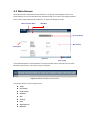
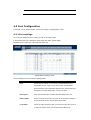
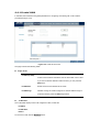
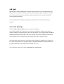
4.1 Main Screen...............................................................................................................................32
4.2 Setup ......................................................................................................................................... 33
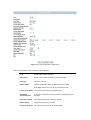
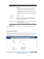
4.2.1 Summary ......................................................................................................................... 33
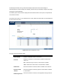
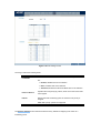
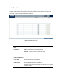
4.2.2 Network Settings.............................................................................................................. 34
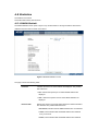
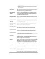
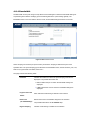
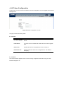
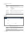
4.2.3 Time................................................................................................................................. 36
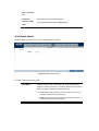
4.3 Port Configuration ...................................................................................................................... 39
4.3.1 Port settings..................................................................................................................... 39
4.3.2 Link Aggregation .............................................................................................................. 43
4.3.3 LACP ...............................................................................................................................45
4.4 VLAN Configuration ................................................................................................................... 46
4.4.1 Create VLAN.................................................................................................................... 47
4.4.2 Port setting....................................................................................................................... 48
4.4.3 Ports to VLAN .................................................................................................................. 49
4.4.4 VLAN to Ports .................................................................................................................. 50
4.4.5 GVRP .............................................................................................................................. 51
4.5 Statistics..................................................................................................................................... 54
4.5.1 RMON Statisti .................................................................................................................. 54
4.5.2 RMON History.................................................................................................................. 56
4.5.3 RMON Alarm.................................................................................................................... 58
4.5.4 RMON Events.................................................................................................................. 61
4.5.5 Port Utilization.................................................................................................................. 63
4.5.6 802.1x Statistic................................................................................................................. 64
4.5.7 GVRP Statistics ............................................................................................................... 65
4.6 ACL ............................................................................................................................................ 67
4.6.1 IP Based ACL .................................................................................................................. 67
4.6.2 MAC Based ACL.............................................................................................................. 70
4.7 Security...................................................................................................................................... 72
4.7.1 ACL Binding ..................................................................................................................... 72
4.7.2 Radius ............................................................................................................................. 73
4.7.3 TACACS+ ........................................................................................................................ 75
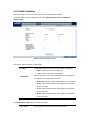
4.7.4 802.1x settings................................................................................................................. 77
4.7.5 Port Security .................................................................................................................... 79
4.7.6 Multiple Hosts .................................................................................................................. 81
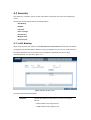
4.7.7 Storm control.................................................................................................................... 82
4.8 QoS............................................................................................................................................ 84
4.8.1 CoS Settings.................................................................................................................... 84
4.8.2 Queue Setting.................................................................................................................. 86
4.8.3 DSCP Settings................................................................................................................. 87
4.8.4 Bandwidth ........................................................................................................................ 88
4.8.5 Basic Mode ...................................................................................................................... 89
4.8.6 Advanced Mode ............................................................................................................... 90
4.9. Spanning Tree........................................................................................................................... 96
4.9.1 STP Status....................................................................................................................... 96
4.9.2 The Global STP ............................................................................................................... 98
4.9.3 STP Port Settings ............................................................................................................ 99
4.9.4 RSTP Port settings ........................................................................................................ 102
4.9.5 MSTP Properties ........................................................................................................... 104
4.9.6 MSTP Instance Settings ................................................................................................ 105
4.9.7 MSTP Interface Settings ................................................................................................ 107
4.10 Multicast................................................................................................................................. 110
4.10.1 IGMP Snooping ........................................................................................................... 110
4.10.2 Bridge Multicast ........................................................................................................... 111
4.10.3 Bridge Multicast Forward All ........................................................................................ 114
4.11 SNMP..................................................................................................................................... 115
4.11.1 Global Parameters ....................................................................................................... 115
4.11.2 Views ........................................................................................................................... 116
4.11.3 Group Profile................................................................................................................ 118
4.11.4 Group Membership ...................................................................................................... 119
4.11.5 Communities ................................................................................................................ 121
4.11.6 Notification Filter .......................................................................................................... 123
4.11.7 Notification Recipient ................................................................................................... 124
4.12 Admin..................................................................................................................................... 127
4.12.1 User Authentication...................................................................................................... 127
4.12.2 Static Address .............................................................................................................. 128
4.12.3 Dynamic Address......................................................................................................... 130
4.12.4 Logging ........................................................................................................................ 131
4.12.5 Port Mirroring ............................................................................................................... 133
4.12.6 Cable Test.................................................................................................................... 134
4.12.7 Save Configuration ...................................................................................................... 135
4.12.8 Firmware Upgrade ....................................................................................................... 136
4.12.9 Reboot ......................................................................................................................... 138
4.12.10 Factory Defaults......................................................................................................... 138
4.12.11 Server Logs................................................................................................................ 139
4.12.12 Memory Logs ............................................................................................................. 141
4.12.13 Flash Logs ................................................................................................................. 141
5. COMMAND STRUCTURE ................................................................................................................ 143
5.1 Connect to PC’s RS-232 serial port ......................................................................................... 143
5.2 Using the CLI ........................................................................................................................... 144
5.2.1 CLI Command Modes.................................................................................................... 144
5.2.2 Starting the CLI .............................................................................................................. 147
5.2.3 Editing Features............................................................................................................. 148
5.3 AAA Commands....................................................................................................................... 151
5.3.1 aaa authentication login ................................................................................................. 151
5.3.2 aaa authentication enable.............................................................................................. 152
5.3.3 login authentication........................................................................................................ 154
5.3.4 enable authentication..................................................................................................... 154
5.3.5 ip http authentication...................................................................................................... 155
5.3.6 ip https authentication .................................................................................................... 156
5.3.7 show authentication methods ........................................................................................ 157
5.3.8 password ....................................................................................................................... 158
5.3.9 enable password............................................................................................................ 159
5.3.10 username..................................................................................................................... 159
5.3.11 show users accounts.................................................................................................... 160
5.4 Address Table Commands ....................................................................................................... 161
5.4.1 bridge address ............................................................................................................... 161
5.4.2 bridge multicast filtering ................................................................................................. 162
5.4.3 bridge multicast address ................................................................................................ 162
5.4.4 bridge multicast forbidden address ................................................................................ 163
3.4.5 bridge multicast forward-unregistered............................................................................ 164
5.4.6 bridge multicast forbidden forward-unregistered............................................................ 165
5.4.7 bridge multicast forward-all ............................................................................................ 166
5.4.8 bridge multicast forbidden forward-all ............................................................................ 167
5.4.9 bridge aging-time ........................................................................................................... 167
5.4.10 clear bridge .................................................................................................................. 168
5.4.11 port security ................................................................................................................. 169
5.4.12 port security routed secure-address ............................................................................ 169
5.4.13 show bridge address-table........................................................................................... 170
5.4.14 show bridge address-table static ................................................................................. 171
5.4.15 show bridge address-table count ................................................................................. 172
5.4.16 show bridge multicast address-table............................................................................ 173
5.4.17 show bridge multicast filtering...................................................................................... 174
5.4.18 show ports security ...................................................................................................... 175
5.5 Clock Commands..................................................................................................................... 176
5.5.1 clock set......................................................................................................................... 176
5.5.2 clock source................................................................................................................... 176
5.5.3 clock timezone ............................................................................................................... 177
5.5.4 clock summer-time......................................................................................................... 178
5.5.5 sntp authentication-key.................................................................................................. 179
5.5.6 sntp authenticate ........................................................................................................... 180
5.5.7 sntp trusted-key ............................................................................................................. 181
5.5.8 sntp client poll timer ....................................................................................................... 181
5.5.9 sntp broadcast client enable .......................................................................................... 182
5.5.10 sntp anycast client enable ........................................................................................... 183
5.5.11 sntp client enable (interface) ........................................................................................ 183
5.5.12 sntp unicast client enable ............................................................................................ 184
5.5.13 sntp unicast client poll.................................................................................................. 185
5.5.14 sntp server ................................................................................................................... 185
5.5.15 show clock ................................................................................................................... 186
5.5.16 show sntp configuration ............................................................................................... 187
5.5.17 show sntp status .......................................................................................................... 188
5.6 Configuration and Image Files ................................................................................................. 189
5.6.1 copy ...............................................................................................................................189
5.6.4 show startup-config........................................................................................................ 193
5.7 Ethernet Configuration Commands.......................................................................................... 195
5.7.1 interface ethernet........................................................................................................... 195
5.7.2 interface range ethernet................................................................................................. 195
5.7.3 shutdown ....................................................................................................................... 196
5.7.4 description ..................................................................................................................... 197
5.7.5 speed............................................................................................................................. 197
5.7.6 duplex ............................................................................................................................ 198
5.7.7 negotiation ..................................................................................................................... 199
5.7.8 flowcontrol...................................................................................................................... 200
5.7.9 mdix ...............................................................................................................................200
5.7.10 back-pressure .............................................................................................................. 201
5.7.11 port jumbo-frame.......................................................................................................... 202
5.7.12 clear counters .............................................................................................................. 202
5.7.13 set interface active....................................................................................................... 203
5.7.14 show interfaces configuration ...................................................................................... 204
5.7.15 show interfaces status ................................................................................................. 205
5.7.16 show interfaces description.......................................................................................... 206
5.7.17 show interfaces counters ............................................................................................. 207
5.7.18 show ports jumbo-frame .............................................................................................. 210
5.7.20 port storm-control broadcast enable ............................................................................ 211
5.7.21 port storm-control broadcast rate................................................................................. 211
5.7.22 show ports storm-control.............................................................................................. 212
5.8 GVRP Commands ................................................................................................................... 213
5.8.1 gvrp enable (global) ....................................................................................................... 213
5.8.2 gvrp enable (interface)................................................................................................... 214
5.8.3 garp timer ...................................................................................................................... 214
5.8.4 gvrp vlan-creation-forbid ................................................................................................ 215
5.8.5 gvrp registration-forbid................................................................................................... 216
5.8.7 clear gvrp statistics ........................................................................................................ 217
5.8.8 show gvrp configuration ................................................................................................. 217
5.8.9 show gvrp statistics........................................................................................................ 218
5.8.10 show gvrp error-statistics ............................................................................................. 219
5.9 IGMP Snooping Commands .................................................................................................... 220
5.9.1 ip igmp snooping (Global) .............................................................................................. 220
5.9.2 ip igmp snooping (Interface) .......................................................................................... 221
5.9.3 ip igmp snooping mrouter .............................................................................................. 222
5.9.4 ip igmp snooping host-time-out...................................................................................... 222
5.9.5 ip igmp snooping mrouter-time-out ................................................................................ 223
5.9.6 ip igmp snooping leave-time-out .................................................................................... 224
5.9.7 show ip igmp snooping mrouter ..................................................................................... 224
5.9.8 show ip igmp snooping interface.................................................................................... 225
5.9.9 show ip igmp snooping groups ...................................................................................... 226
5.10 IP Addressing Commands ..................................................................................................... 227
5.10.1 ip address .................................................................................................................... 227
5.10.2 ip address dhcp ........................................................................................................... 227
5.10.3 ip default-gateway........................................................................................................ 229
5.10.4 show ip interface.......................................................................................................... 229
5.10.5 arp ...............................................................................................................................230
5.10.6 arp timeout................................................................................................................... 231
5.10.7 clear arp-cache ............................................................................................................ 232
5.10.8 show arp ...................................................................................................................... 232
5.11 LACP Commands .................................................................................................................. 233
5.11.1 lacp system-priority ...................................................................................................... 233
5.11.2 lacp port-priority ........................................................................................................... 234
5.11.3 lacp timeout.................................................................................................................. 234
5.11.4 show lacp ethernet ....................................................................................................... 235
5.11.5 show lacp port-channel ................................................................................................ 236
5.12 Line Commands..................................................................................................................... 236
5.12.1 line ...............................................................................................................................236
5.12.2 speed ........................................................................................................................... 237
5.12.3 exec-timeout ................................................................................................................ 238
5.12.4 show line...................................................................................................................... 238
5.13 Management ACL Commands ............................................................................................... 240
5.13.1 management access-list .............................................................................................. 240
5.13.2 permit (management) .................................................................................................. 241
5.13.3 deny (management)..................................................................................................... 242
5.13.4 management access-class .......................................................................................... 243
5.13.5 show management access-list..................................................................................... 243
User Guidelines ...................................................................................................................... 244
5.13.6 show management access-class ................................................................................. 244
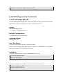
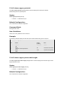
5.14 PHY Diagnostics Commands................................................................................................. 245
5.14.1 test copper-port tdr ...................................................................................................... 245
5.14.2 show copper-ports tdr .................................................................................................. 246
5.14.3 show copper-ports cable-length................................................................................... 246
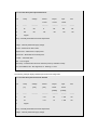
5.14.4 show fiber-ports optical-transceiver ............................................................................. 247
5.15 Port Channel Commands....................................................................................................... 249
5.15.1 interface port-channel .................................................................................................. 249
5.15.2 interface range port-channel ........................................................................................ 250
5.15.3 channel-group.............................................................................................................. 250
5.15.4 show interfaces port-channel ....................................................................................... 251
5.16 Port Monitor Commands ........................................................................................................ 252
5.16.1 port monitor.................................................................................................................. 252
5.16.2 show ports monitor ...................................................................................................... 253
5.17 QoS Commands .................................................................................................................... 255
5.17.1 qos...............................................................................................................................255
5.17.2 show qos...................................................................................................................... 255
5.17.3 wrr-queue cos-map...................................................................................................... 256
5.17.4 wrr-queue bandwidth ................................................................................................... 257
5.17.5 priority-queue out num-of-queues................................................................................ 258
5.17.6 show qos interface....................................................................................................... 259
5.17.7 qos map dscp-queue ................................................................................................... 262
5.17.8 qos trust (Global) ......................................................................................................... 263
5.17.9 qos trust (Interface)...................................................................................................... 264
5.17.10 qos cos ...................................................................................................................... 264
5.17.11 qos cos override......................................................................................................... 265
5.17.12 show qos map............................................................................................................ 266
5.18 Radius Commands ................................................................................................................ 267
5.18.1 radius-server host ........................................................................................................ 267
5.18.2 radius-server key ......................................................................................................... 269
5.18.3 radius-server retransmit ............................................................................................... 269
5.18.4 radius-server source-ip ................................................................................................ 270
5.18.5 radius-server timeout ................................................................................................... 271
5.18.6 radius-server deadtime ................................................................................................ 271
5.18.7 show radius-servers..................................................................................................... 272
5.19 RMON Commands................................................................................................................. 273
5.19.1 show rmon statistics..................................................................................................... 273
5.19.2 rmon collection history ................................................................................................. 275
5.19.3 show rmon collection history........................................................................................ 276
5.19.4 show rmon history........................................................................................................ 277
5.19.5 rmon alarm................................................................................................................... 280
5.19.6 show rmon alarm-table ................................................................................................ 282
5.19.7 show rmon alarm ......................................................................................................... 282
5.19.8 rmon event................................................................................................................... 284
5.19.9 show rmon events........................................................................................................ 285
5.19.10 show rmon log ........................................................................................................... 286
5.19.11 rmon table-size........................................................................................................... 288
5.20 SNMP Commands ................................................................................................................. 288
5.20.1 snmp-server community .............................................................................................. 288
5.20.2 snmp-server contact .................................................................................................... 290
5.20.3 snmp-server location ................................................................................................... 291
5.20.4 snmp-server enable traps ............................................................................................ 291
5.20.5 snmp-server trap authentication .................................................................................. 292
5.20.6 snmp-server host ......................................................................................................... 292
5.20.7 snmp-server set ........................................................................................................... 294
5.20.8 show snmp................................................................................................................... 294
5.21 Spanning-Tree Commands .................................................................................................... 296
5.21.1 spanning-tree............................................................................................................... 296
5.21.2 spanning-tree mode ..................................................................................................... 296
5.21.3 spanning-tree forward-time .......................................................................................... 297
5.21.4 spanning-tree hello-time .............................................................................................. 298
5.21.5 spanning-tree max-age ................................................................................................ 298
5.21.6 spanning-tree priority ................................................................................................... 299
5.21.7 spanning-tree disable .................................................................................................. 300
5.21.8 spanning-tree cost ....................................................................................................... 300
5.21.9 spanning-tree port-priority............................................................................................ 301
5.21.10 spanning-tree portfast ................................................................................................ 302
5.21.11 spanning-tree link-type............................................................................................... 302
5.21.13 spanning-tree bpdu .................................................................................................... 304
5.21.14 clear spanning-tree detected-protocols...................................................................... 304
5.21.15 show spanning-tree ................................................................................................... 305
5.22 SSH and SLOGIN Commands............................................................................................... 307
5.22.1 ip ssh port .................................................................................................................... 307
5.22.2 ip ssh server ................................................................................................................ 308
5.22.3 crypto key generate dsa .............................................................................................. 308
5.22.4 crypto key generate rsa ............................................................................................... 309
5.22.5 ip ssh pubkey-auth....................................................................................................... 310
5.22.6 crypto key pubkey-chain ssh........................................................................................ 310
5.22.7 user-key ....................................................................................................................... 311
5.22.8 key-string ..................................................................................................................... 312
5.22.9 show ip ssh .................................................................................................................. 313
5.22.10 show crypto key mypubkey........................................................................................ 314
5.22.11 show crypto key pubkey-chain ssh ............................................................................ 314
5.23 System Management ............................................................................................................. 315
5.23.1 ping .............................................................................................................................. 315
5.23.2 traceroute..................................................................................................................... 317
5.23.3 telnet ............................................................................................................................ 319
5.23.4 resume......................................................................................................................... 322
5.23.5 reload........................................................................................................................... 323
5.23.6 hostname ..................................................................................................................... 323
5.23.7 show users................................................................................................................... 324
5.23.8 show sessions ............................................................................................................. 324
5.23.9 show system ................................................................................................................ 325
5.23.10 show version.............................................................................................................. 327
5.24 Syslog Commands................................................................................................................. 327
5.24.1 logging on .................................................................................................................... 327
5.24.2 logging ......................................................................................................................... 328
5.24.3 logging console............................................................................................................ 329
5.24.4 logging buffered ........................................................................................................... 330
5.24.5 logging buffered size.................................................................................................... 330
5.24.6 clear logging ................................................................................................................ 331
5.24.7 logging file.................................................................................................................... 332
5.24.8 clear logging file........................................................................................................... 332
5.24.9 show logging................................................................................................................ 333
5.24.10 show logging file ........................................................................................................ 334
5.24.11 show syslog-servers................................................................................................... 335
5.25 TACACS Commands ............................................................................................................. 336
5.25.1 tacacs-server host ....................................................................................................... 336
5.25.2 tacacs-server key......................................................................................................... 337
5.25.3 tacacs-server timeout................................................................................................... 338
5.25.4 tacacs-server source-ip................................................................................................ 339
5.25.5 show tacacs ................................................................................................................. 340
5.26 User Interface Commands ..................................................................................................... 341
5.26.1 enable .......................................................................................................................... 341
5.26.2 disable ......................................................................................................................... 342
5.26.3 configure ...................................................................................................................... 342
5.26.4 login ............................................................................................................................. 343
5.26.5 exit(configuration) ........................................................................................................ 343
5.26.6 exit(EXEC) ................................................................................................................... 344
5.26.7 end...............................................................................................................................345
5.26.8 help .............................................................................................................................. 345
5.26.9 history .......................................................................................................................... 346
5.26.10 history size................................................................................................................. 346
5.26.12 show history............................................................................................................... 347
5.26.13 show privilege ............................................................................................................ 348
5.27 VLAN Commands .................................................................................................................. 348
5.27.1 vlan database .............................................................................................................. 348
5.27.2 vlan .............................................................................................................................. 349
5.27.3 default-vlan disable...................................................................................................... 350
5.27.4 interface vlan ............................................................................................................... 350
5.27.5 interface range vlan ..................................................................................................... 351
5.27.6 name............................................................................................................................ 352
5.27.7 switchport mode........................................................................................................... 352
5.27.8 switchport access vlan ................................................................................................. 353
5.27.9 switchport trunk allowed vlan ....................................................................................... 354
5.27.10 switchport trunk native vlan........................................................................................ 354
5.27.11 switchport general allowed vlan ................................................................................. 355
5.27.12 switchport general pvid .............................................................................................. 356
5.27.13 switchport general ingress-filtering disable ................................................................ 357
5.27.14 switchport general acceptable-frame-type taggedonly............................................... 357
5.27.15 switchport forbidden vlan ........................................................................................... 358
5.27.16 map protocol protocols-group .................................................................................... 359
5.27.17 switchport general map protocols-group vlan ............................................................ 360
5.27.18 ip internal-usage-vlan ................................................................................................ 361
5.27.19 show vlan................................................................................................................... 361
5.27.20 show vlan internal usage ........................................................................................... 362
5.27.22 show interfaces switchport......................................................................................... 363
5.28 Web Server Commands......................................................................................................... 364
5.28.1 ip http server ................................................................................................................ 364
5.28.2 ip http port.................................................................................................................... 365
5.28.3 ip https server .............................................................................................................. 365
5.28.4 ip https port .................................................................................................................. 366
5.28.5 crypto certificate generate ........................................................................................... 367
5.28.6 show ip http.................................................................................................................. 367
5.28.7 show ip https................................................................................................................ 368
5.29 802.1x Commands................................................................................................................. 369
5.29.1 aaa authentication dot1x.............................................................................................. 369
5.29.2 dot1x system-auth-control............................................................................................ 370
5.29.3 dot1x port-control......................................................................................................... 370
5.29.4 dot1x re-authentication ................................................................................................ 371
5.29.5 dot1x timeout re-authperiod ......................................................................................... 372
5.29.6 dot1x re-authenticate ................................................................................................... 372
5.29.7 dot1x timeout quiet-period ........................................................................................... 373
5.29.8 dot1x timeout tx-period ................................................................................................ 374
5.29.9 dot1x max-req.............................................................................................................. 375
5.29.10 dot1x timeout supp-timeout........................................................................................ 375
5.29.11 dot1x timeout server-timeout...................................................................................... 376
5.29.12 show dot1x................................................................................................................. 377
5.29.13 show dot1x users....................................................................................................... 379
5.29.14 show dot1x statistics .................................................................................................. 380
5.29.15 dot1x auth-not-req ..................................................................................................... 382
5.29.17 dot1x multiple-hosts ................................................................................................... 383
5.29.18 dot1x single-host-violation ......................................................................................... 383
5.29.19 show dot1x advanced ................................................................................................ 384
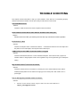
TROUBLE SHOOTING ......................................................................................................................... 386
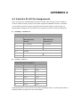
APPENDEX A ....................................................................................................................................... 387
A.1 Switch's RJ-45 Pin Assignments ............................................................................................. 387
A.2 RJ-45 cable pin assignment .................................................................................................... 388
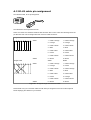
A.3 Available Modules.................................................................................................................... 389
1. INTRODUCTION
Packet Contents
Check the contents of your package for following parts:
• Managed Fast Ethernet Switch x1
• CD-ROM user's manual x1
• Quick installation guide x1
• 19" rack mounting kit x1
• AC adapter x1
• RS-232 console x 1
• Rubber feet x 4
If any of these are missing or damaged, please contact your dealer immediately, if possible, retain the
carton including the original packing material, and use them against to repack the product in case there is
a need to return it to us for repair.
How to Use This Manual
This User Manual is structured as follows:
• Section 2, Installation
The section explains the functions of the Switch and how to physically install the Switch.
• Section 3, Configuration
The section contains the information about the software function of the Switch.
• Section 4, Switch Operation
The section contains specifications of the Switch.
• Appendex A
The section contains cable information of the Switch.
In the following section, terms "SWITCH" with upper case denotes the WGSD-1022 Managed Ethernet
switch. Terms with lower case "switch" means other Ethernet switch devices.
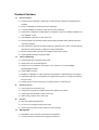
Product Feature
Generic Features
Complies with the IEEE 802.3, IEEE 802.3u, IEEE 802.3ab, IEEE 802.3z Gigabit Ethernet
standard
8-Port 10/100Mbps TP interfaces with auto-negotiation.
2 10/100/1000Mbps TP ports and 2 SFP shared combo interfaces
Supports auto-negotiation and Half-Duplex / Full-Duplex modes for all 10Base-T/100Base-TX
and 1000Base-T ports.
Auto-MDI/MDI-X detection on each RJ-45 port
Prevents packet loss with back pressure (Half-Duplex) and IEEE 802.3x PAUSE frame flow
control (Full-Duplex)
High performance Store and Forward architecture, broadcast storm control, runt/CRC filtering
eliminates erroneous packets to optimize the network bandwidth
8K MAC address table, automatic source address learning and ageing
1Mbit embedded memory for packet buffers
Layer-2 Switching
Supports IEEE 802.1Q Tagged based VLAN
GVRP protocol for VLAN Management
Support up to 4 Trunk groups, each trunk for up to maximum 4 port with 800Mbps
bandwidth(Duplex Mode)
Support IGMP Snooping
IEEE802.1d, IEEE802.1w, classic Spanning Tree Algorithm or Rapid Spanning Tree support
Supports the IEEE 802.1s specification for multiple spanning trees on a single port (spanning
tree per VLAN).
Port Mirroring to monitor the incoming or outgoing traffic on a particular port
Quality of Service
4 priority queues on all switch ports.
Support for strict priority and weighted round robin (WRR) CoS policies
Support QoS and bandwidth control on each port
Traffic-policing policies on the switch port
Security
802.1x Port-Based Authentication
L2-L4 ACL to management the per-flow traffic
Port Security to limit the number of clients to access network
Management
WEB-Based, Telnet, Console Command Line management
Console interface for Switch basic management and setup
Access through SNMPv1,v2c and v3 security set and get requests.
Four groups (history, statistics, alarms, and events) of embedded remote monitoring (RMON)
agents for network monitoring and traffic analysis
Built-in Trivial File Transfer Protocol (TFTP) client
Virtual Cable Test (VCT) technology provides the mechanism to detect and report potential
cabling issues, such as cable opens, cable shorts, etc. on Copper Links
EMI standards comply with FCC, CE class A,WEEE RoHS
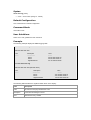
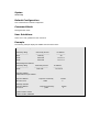
Product Specification
Product
WGSD-1022
8-Port 10/100Mbps + 2 Gigabit TP / SFP combo Managed Ethernet Switch
Hardware Specification
Ports
8 10/ 100Base-TX RJ-45 Auto-MDI/MDI-X ports
Gigabit ports
2 10/100/1000Mbps ports and 2 SFP interfaces
Switch Processing
Scheme
Store-and-forward
Switch fabric
5.6Gbps / Non-Blocking
Throughput
4.17Mpps / Wire-Speed
Address Table
8K entries
Share data Buffer
1 Mbit
Flow Control
Back pressure for Half-Duplex, IEEE 802.3x Pause Frame for Full-Duplex
Dimension
267 x 170 x 45mm (W x D x H), 1U height
Weight
1.2 KG
Power Requirement
100~240V AC, 50-60, Auto-sensing
Power Consumption
13.2 Watts / 45 BTU
Management Interface
Console. Telnet, SSH, Web, SSL, SNMP
Smart function
System Configuration
Port configuration
Port Status
Console interface
Port disable/enable. Auto-negotiation 10/100Mbps full and half duplex mode
selection. Flow control Disable / Enable. Bandwidth control on each port.
Display each port’s speed duplex mode, link status, Flow control status. Auto
negotiation status, trunk status.
VLAN
802.1q Tagged Based VLAN ,up to 255 VLAN groups
Port trunking
Support 4 groups of 4-Port trunk support
QoS
Traffic classification based on Port Number, 802.1p priority, DS/TOS field in
IP Packet
IGMP Snooping
Allow to disable or enable.
Standards Conformance
Regulation Compliance
FCC Part 15 Class A, CE
IEEE802.3 10BASE-T
IEEE802.3u 100BASE-TX/100BASE-FX
IEEE802.3z Gigabit SX/LX
IEE802.3ab Gigabit 1000T
Standards Compliance
IEEE802.3x Flow Control and Back pressure
IEEE802.3ad Port trunk with LACP
IEEE802.1d Spanning tree protocol
IIEEE802.1w Rapid spanning tree protocol
IEEE802.1p Class of service
IEEE802.1Q VLAN Tagging
Environment
Regulation Compliance
FCC Part 15 Class A, CE
Operating Temperature
0℃~50℃,
Storage Temperature
-40℃~70℃,
Operating Humidity
5% to 90%, relative humidity, non-condensing
Storage Humidity
5% to 90%, relative humidity, non-condensing
2. INSTALLATION
This section describes the functionalities of the Switch's components and guides how to install it on the
desktop or shelf. Basic knowledge of networking is assumed. Please read this chapter completely before
continuing.
2.1 Product Description
The PLANET WGSD-1022 is a 8-Port 10/100Mbps with 2 shared SFP/copper GbE interface Gigabit
Ethernet Switch. It boasts a high performance switch architecture that is capable of providing
non-blocking switch fabric and wire-speed throughput as high as 5.6Gbps. Its two built-in GbE uplink
ports also offer incredible extensibility, flexibility and connectivity to the Core switch or Servers.
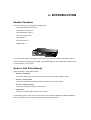
2.1.1 Product Overview
PLANET WGSD-1022 is loaded with powerful traffic management and QoS features to enhance services
offered by telcos. It provides 4 priority queues per port for different types of traffics, allowing
administrators to set policies for classified filtering and rule-based rate limitation. The WGSD-1022
prioritizes applications with WFQ (Weighted Fair Queuing) scheduling algorithm to allocate more
bandwidth to key traffics such as voice transmission, empowering the enterprise to take full advantages
of the limited network resources and guarantee the best performance.
PLANET WGSD-1022 offers comprehensive Access Control List (ACL) for enforcing security to the edge.
Its protection mechanisms comprised of port-based 802.1x user and device authentication. The
administrators can now construct highly secured corporate networks with time and effort considerably
less then before.
With its built-in web-based management, the PLANET WGSD-1022 offers an easy-to-use,
platform-independent management and configuration facility. The PLANET WGSD-1022 supports
standard Simple Network Management Protocol (SNMP) and can be managed via any standard-based
management software. For text-based management, the WGSD-1022 can also be accessed via Telnet
and the console port. For secure remote management, the WGSD-1022 support SSL and SSH
connection which encrypt the packet content at each session.
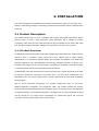
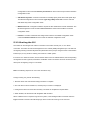
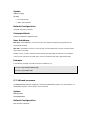
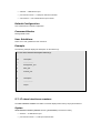
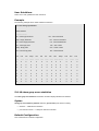
2.1.2 Switch Front Panel
Figure 2-1 shows the front panel of the switch.
38400, N, 8, 1
Intelligent 8-Port 10/100Mbps+2 Gigabit Ethernet Switch
G1
LNK/ACT
mini-GBIC
G2
mini-GBIC
100
G1/G2
LNK/ACT
1000
PWR
1
2
3
4
5
6
7
8
9
9
10
10
Figure 2-1 WGSD-1022 front panel.
2.1.3 LED Indications
System
LED
Color
PWR
Green
Function
Lights to indicate that the Switch has power.
Per 10/100Mbps port
LED
Color
Function
Lights to indicate the link through that port is successfully established.
LNK/ACT
Green
Blink: indicate that the switch is actively sending or receiving data over that
port.
100
Orange
Lights to indicate the port is running in 100Mbps speed.
Off: indicate that the port is operating at 10Mbps.
Per 10/100/1000Base-T port /SFP interfaces
LED
Color
Function
Lights to indicate the link through that port is successfully established.
LNK/ACT
Green
Blink: indicate that the switch is actively sending or receiving data over that
port.
1000
Orange
Lights to indicate the port is running in 1000Mbps speed.
Off: indicate that the port is operating at 10Mbps or 100Mbps.
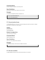
2.1.4 Switch Rear Panel
Figure 2-2 shows the rear panel of the switch
Figure 2-2 WGSD-1022 rear panel.
Power Notice:
1.
The device is a power-required device, it means, it will not work till it is powered. If your
networks should active all the time, please consider using UPS (Uninterrupted Power Supply)
for your device. It will prevent you from network data loss or network downtime.
2.
In some area, installing a surge suppression device may also help to protect your switch from
being damaged by unregulated surge or current to the Switch or the power adapter.
2.2 Install the Switch
This section describes how to install the Ethernet Switch and make connections to it. Please read the
following topics and perform the procedures in the order being presented.
2.2.1 Desktop Installation
To install the Switch on desktop or shelf, please follows these steps:
Step1: Attach the rubber feet to the recessed areas on the bottom of the switch.
Step2: Place the switch on the desktop or the shelf near an AC power source.
Step3: Keep enough ventilation space between the switch and the surrounding objects.
#Note:
When choosing a location, please keep in mind the environmental restrictions
discussed in Chapter 1, Section 4, and Specification.
Step4: Connect the Switch to network devices.
A.
Connect one end of a standard network cable to the 10/100 RJ-45 ports or Gigabit RJ-45 / SFP
mini-GBIC slot on the front of the Switch
B.
Connect the other end of the cable to the network devices such as printer servers, workstations
or routers…etc.
#Note:
Connection to the Switch requires UTP Category 5 network cabling with RJ-45 tips.
For more information, please see the Cabling Specification in Appendix A.
Step5: Supply power to the switch.
A.
Connect one end of the power cable to the switch.
B.
Connect the power plug of the power cable to a standard wall outlet.
When the switch receives power, the Power LED should remain solid Green.
2.2.2 Rack Mounting
To install the switch in a 19-inch standard rack, please follows the instructions described below.
Step1: Place the switch on a hard flat surface, with the front panel positioned towards the front side.
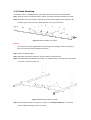
Step2: Attach the rack-mount bracket to each side of the switch with supplied screws attached to the
package. Figure 2-5 shows how to attach brackets to one side of the switch.
Figure 2-5 Attach brackets to the switch.
Caution:
You must use the screws supplied with the mounting brackets. Damage caused to the parts by
using incorrect screws would invalidate the warranty.
Step3: Secure the brackets tightly.
Step4: Follow the same steps to attach the second bracket to the opposite side.
Step5: After the brackets are attached to the Switch, use suitable screws to securely attach the brackets
to the rack, as shown in Figure 2-6
Figure 2-6 Mounting the Switch in a Rack
Step6: Proceeds with the steps 4 and steps 5 of session 2.2.1 Desktop Installation to connect the
network cabling and supply power to the switch.
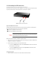
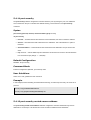
2.2.3 Installing the SFP transceiver
The sections describe how to insert an SFP transceiver into an SFP slot.
The SFP transceivers are hot-plug e and hot-swappable. You can plug-in and out the transceiver to/from
any SFP port without having to power down the Switch. As the Figure 2-7 appears.
Figure 2-7 Plug-in the SFP transceiver
Approved PLANET SFP Transceivers
PLANET WGSD-1022 support both single mode and multi mode SFP transceiver. The following list of
approved PLANET SFP transceivers is correct at the time of publication:
■MGB-SX SFP (1000BASE-SX SFP transceiver )
■MGB-LX SFP (1000BASE-LX SFP transceiver )
#Note:
It recommends using PLANET SFPs on the Switch. If you insert a SFP transceiver
that is not supported, the Switch will not recognize it.
Before connect the other switches, workstation or Media Converter.
1.
Make sure both side of the SFP transfer are with the same media type, for example: 1000Base-SX to
1000Base-SX, 1000Bas-LX to 1000Base-LX.
2.
Check the fiber-optic cable type match the SFP transfer model.
¾
To connect to 1000Base-SX SFP transfer, use the multi-mode fiber cable- with one side must
be male duplex LC connector type.
¾
To connect to 1000Base-LX SFP transfer, use the single-mode fiber cable-with one side
must be male duplex LC connector type.
Connect the fiber cable
1.
Attach the duplex LC connector on the network cable into the SFP transceiver.
2.
Connect the other end of the cable to a device – switches with SFP installed, fiber NIC on a
workstation or a Media Converter..
3.
Check the LNK/ACT LED of the SFP slot on the front of the Switch. Ensure that the SFP transceiver
is operating correctly.
4.
Check the Link mode of the SFP port if the link failed. Co works with some fiber-NICs or Media
Converters, set the Link mode to “1000 Force” is needed.
3. CONFIGURATION
This chapter explains the methods that you can use to configure management access to the switch. It
describes the types of management applications and the communication and management protocols that
deliver data between your management device (work-station or personal computer) and the system. It
also contains information about port connection options.
This chapter covers the following topics:
Management Access Overview
Key Concepts
Key Guidelines for Implementation
Administration Console Access
Web Management Access
SNMP Access
Standards, Protocols, and Related Reading
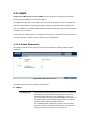
3.1 Management Access Overview
The switch gives you the flexibility to access and manage the switch using any or all of the following
methods:
An administration console
Web browser interface
An external SNMP-based network management application
The administration console and Web browser interface support are embedded in the switch software and
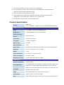
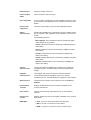
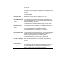
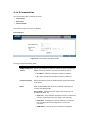
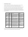
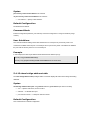
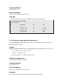
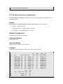
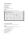
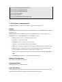
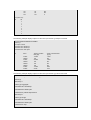
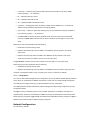
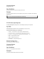
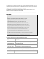
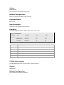
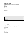
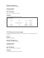
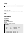
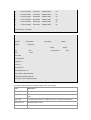
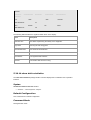
are available for immediate use. Each of these management methods has their own advantages. Table
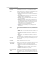
3-1 compares the three management methods.
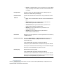
Method
Advantages
Disadvantages
Console
‧No IP address or subnet needed
‧Must be near switch or use dial-up
‧Text-based
connection
‧Telnet functionality and HyperTerminal
‧Not convenient for remote users
built into Windows 95/98/NT/2000/ME/XP
‧Modem connection may prove to be
operating systems
unreliable or slow
‧Secure
Web
‧Ideal for configuring the switch remotely
‧Security can be compromised
Browser
‧Compatible with all popular browsers
(hackers need only know the IP address
‧Can be accessed from any location
and subnet mask)
‧Most visually appealing
‧May encounter lag times on poor
connections
SNMP
‧Communicates with switch functions at
‧Requires SNMP manager software
Agent
the MIB level
‧Least visually appealing of all three
‧Based on open standards
methods
‧Some settings require calculations
‧Security can be compromised
(hackers need only know the
community name)
Table 3-1 Management Methods Comparison
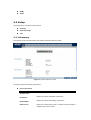
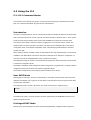
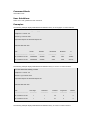
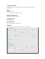
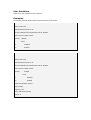
3.1.1 Administration Console
The administration console is an internal, character-oriented, and command line user interface for
performing system administration such as displaying statistics or changing option settings. Using this
method, you can view the administration console from a terminal, personal computer, Apple Macintosh,
or workstation connected to the switch's console (serial) port.
There are two ways to use this management method: via direct access or modem port access. The
following sections describe these methods. For more information about using the console, refer to
Chapter 5 Command Line Interface Console Management.
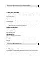
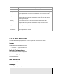
3.1.2 Direct Access
Direct access to the administration console is achieved by directly connecting a terminal or a PC
equipped with a terminal-emulation program (such as HyperTerminal) to the switch console (serial) port.
When using this management method, a null-modem cable is required to connect the switch to the PC.
After making this connection, configure the terminal-emulation program to use the following parameters:
The default parameters are:
384,00 bps
8 data bits
No parity
1 stop bit
You can change these settings, if desired, after you log on. This management method is often preferred
because you can remain connected and monitor the system during system reboots. Also, certain error
messages are sent to the serial port, regardless of the interface through which the associated action was
initiated. A Macintosh or PC attachment can use any terminal-emulation program for connecting to the
terminal serial port. A workstation attachment under UNIX can use an emulator such as TIP.
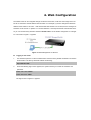
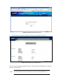
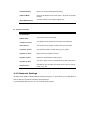
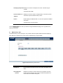
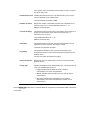
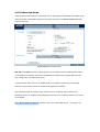
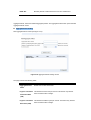
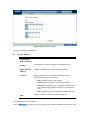
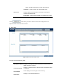
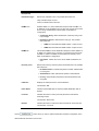
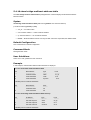
3.2 Web Management
The switch provides a browser interface that lets you configure and manage the switch remotely. After
you set up your IP address for the switch, you can access the switch's Web interface applications directly
in your Web browser by entering the IP address of the switch. You can then use your Web browser to list
and manage switch configuration parameters from one central location, just as if you were directly
connected to the switch's console port.
Web Management requires either Microsoft Internet Explorer 4.01 or later or Netscape Navigator 4.03 or
later.
3.3 SNMP-Based Network Management
You can use an external SNMP-based application to configure and manage the switch. This
management method requires the SNMP agent on the switch and the SNMP Network Management
Station to use the same community string. This management method, in fact, uses two community strings:
the get community string and the set community string. If the SNMP Net-work management Station only
knows the set community string, it can read and write to the MIBs. However, if it only knows the get
community string, it can only read MIBs. The default gets and sets community strings for the switch are
public.
3.4 Protocols
The switch supports the following protocols:
Virtual terminal protocols, such as Telnet
Simple Network Management Protocol (SNMP)
3.4.1 Virtual Terminal Protocols
A virtual terminal protocol is a software program, such as Telnet, that allows you to establish a
management session from a Macintosh, a PC, or a UNIX workstation. Because Telnet runs over TCP/IP,
you must have at least one IP address configured on the switch before you can establish access to it with
a virtual terminal protocol.
#Note:
Terminal emulation differs from a virtual terminal protocol in that you must connect a
terminal directly to the console (serial) port.
3.4.2 SNMP Protocol
Simple Network Management Protocol (SNMP) is the standard management protocol for multi-vendor IP
networks. SNMP supports transaction-based queries that allow the protocol to format messages and to
transmit information between reporting devices and data-collection programs. SNMP runs on top of the
User Datagram Protocol (UDP), offering a connectionless-mode service.
3.4.3 Management Architecture
All of the management application modules use the same Messaging Application Programming Interface
(MAPI). By unifying management methods with a single MAPI, configuration parameters set using one
method (console port, for example) are immediately displayable by the other management methods (for
example, SNMP agent of Web browser).
The management architecture of the switch adheres to the IEEE open standard. This compliance
assures customers that the switch is compatible with, and will interoperate with other solutions that
adhere to the same open standard.
4. Web Configuration
The WGSD-1022 can be configured through an Ethernet connection, make sure the manager PC must
be set on same the IP subnet address with the switch. For example, if you have changed the default IP
address of the Switch to 192.168.1.1 with subnet mask 255.255.255.0 via console, then the manager PC
should be set at 192.168.1.x (where x is a number between 1 and 253) with subnet mask 255.255.255.0.
Or you can use the factory default IP address 192.168.1.254 to do the relative configuration on manager
PC. The sceen in Figure 4-1 appears.
Figure 4-1 Web Management via ethernet
1.
Logging on the switch
Use Internet Explorer 5.0 or above Web browser. Enter the factory-default IP address to access the
Web interface. The factory-default IP Address as following:
http://192.168.1.254
2.
When the following login screen appears, the system will ask you to enter the username and
password.
Default User name: admin
Default Password: admin
The login screen in Figure 4-2 appears.
Figure 4-2 WGSD-1022 Web Login screen
3.
After entering the username and password, the main screen appears as Figure 4-3.
Figure 4-3 Web Main Screen of WGSD-1022
Now, you can use the Web management interface to continue the switch management or manage the
switch by console interface.
#Note:
It is recommended to use Internet Explore 6.0 or above to access WGSD-1022.
4.1 Main Screen
The Switch provides a Web-based browser interface for configuring and managing the Switch. This
interface allows you to access the switch using the Web browser of your choice. This chapter describes
how to use the switch’s Web browser interface to con-figure and manage the switch.
Main Functions Menu
Sub Menu
Port Link Status
Main Screen
Description
Figure 4-1
Save Config
Via the Web-Management, the administrator can setup the WGSD-1022 by select the functions those
listed in the Main Function. The screen in Figure 4-2 appears.
Figure 4-2 WGSD-1022 Main Funcrions Menu
The following functions can be configured here:
Setup
Port Config
VLAN Config
Statistics
ACL
Security
QoS
Spanning Tree
Multicast
SNMP
Admin
4.2 Setup
The Setup menus include the tree sub-menus:
Summary
Network Settings
Time
4.2.1 Summary
The summary screen provides Device and System Information about the Switch.
Figure 4-3 System Summary screen
The page contains the following informations:
Device Information
• System Name
Display your system name
• IP Address
Display the current IP address of the device
• Subnet Mask
Display the subnet mask setting of the device
• DNS Servers
Display the current DNS Servers, no matter by manual setting or
assigned by the DHCP server
• Default Gateway
Display the current default gateway setting
• Address Mode
Show the IP Address mode of the system – By Static or Dynamic
(DHCP)
• Base MAC Address
The MAC address of the Switch displays here
System Information
• Serial Number
The unique box serial number for this switch
• Model Name
The product name of this switch
• Hardware Version
The release version maintenance number of the hardware
• Boot Version
The version of boot system currently running on the switch
• Firmware Version
The operating system currently running on the switch
• System Location
Display where the Switch is located
• System Contact
Display the administrative contact person
• System Up Time
The time in days, hours and minutes since the last switch reboot
• Current Time
Specifies the time and date. The format is hour, minute, second,
month, day, year
4.2.2 Network Settings
The Basic Setup Table include the Network Settings (see figure 4-3), which allows you to assign DHCP or
static IP settings to interfaces and assign default gateways.
In the Networking Setting screen, you can set these parts as below:
Figure 4-4 Network Setting screen
The page includes the following fields:
Identification:
• System Name
Type your system name
• System Location
Type where the Switch is located
• System Contact
Enter the administrative contact person
• System Object ID
Tthe system object identifier is in this field
• Base MAC Address
The MAC address of the Switch displays here
IP Configuration:
• Management VLAN
Where you can select the Management VLAN.
The default Managemanet VLAN is VLAN 1
• IP Address Mode
Where select Static or Dynamic IP address configuration.
The Default Mode is Static
• Host Name
In this field you can enter the DHCP Host Name
• IP Address
Enter the IP address when you want to use a static address.
The default IP Address is 192.168.1.254
• Subnet Mask
Enter the IP subnet mask for the interface.
The factory default value is 255.255.255.0
• Deafault Gateway
Enter the default gateway for the IP interface.
The factory default value is 0.0.0.0
• DNS Server
Enter the IP Address of the DNS Server. The Domain Name System
(DNS) converts user-defined domain names into IP addresses.
4.2.3 Time
In the Basic Setup Table, you can see the Time Setup (see figure 4-5), by which you can configure the
time settings for the Switch.
You can select SNTP Servers: Server1 for the primary SNTP server and Server2 for the secondary SNTP
server.
Figure 4-5 Time screen
The Time page includes the following fields:
Set Time
• Use System Time
Specifies that the system time is not set by an external source but the
Local time settings.
• Use SNTP Time
Local Time
• Hours / Minuntes /
Seconds
Specifies that the system time is set via an SNTP server
Defines the system time. The field format is HH:MM:SS, for example,
21:15:03.
• Month / Day / Year
Defines the system date. The field format is Day:Month:Year, for
example, 04 May 2050.
• Time Zone
The difference between Greenwich Mean Time (GMT) and local time.
For example, the Time Zone Offset for Paris is GMT +1, while the
local time in Taipei is GTM +8.
Daylight Saving
• Daylight Saving
Enables the Daylight Savings Time (DST) on the device based on the
devices location. The possible field values are:
• USA -- The device switches to DST at 2 a.m. on the first Sunday
of April, and reverts to standard time at 2 a.m. on the last
Sunday of October.
• European -- The device switches to DST at 1:00 am on the last
Sunday in March and reverts to standard time at 1:00 am on the
last Sunday in October. The European option applies to EU
members, and other European countries using the EU standard.
• Other -- The DST definitions are user-defined based on the
device locality. If Other is selected, the From and To fields must
be defined.
• Time Set Offset
For non USA and European countries, the amount of time for DST
can be set in minutes. The value range is (1-1440).
The default time is 60 minutes.
• From
Defines the time that DST begins in countries other than USA or
Europe, in the format DayMonthYear in one field and time in another.
For example, DST begins on the 25th October 2007 5:00 am, the two
fields will be 25Oct07 and 5:00. The possible field values are:
• Date -- The date at which DST begins. The possible field range
is 1-31.
• Month -- The month of the year in which DST begins. The
possible field range is Jan-Dec.
• Year-- The year in which the configured DST begins.
• Time -- The time at which DST begins. The field format is
Hour:Minute, for example, 05:30.
• To
Defines the time that DST ends in countries other than USA or
European in the format DayMonthYear in one field and time in
another. For example, DST ends on the 23rd March 2008 12:00 am,
the two fields will be 23Mar08 and 12:00. The possible field values
are:
• Date -- The date at which DST ends. The possible field range is
1-31.
• Month -- The month of the year in which DST ends. The
possible field range is Jan-Dec.
• Year-- The year in which the configured DST ends.
• Time -- The time at which DST starts. The field format is
Hour:Minute, for example, 05:30.
• Recurring
Defines the time that DST starts in countries other than USA or
Europe where the DST is constant year to year. The possible field
values are:
• From
Defines the time that DST begins each year. For example, DST
begins locally every second Sunday in April at 5:00 am. The possible
field values are:
• Day -- The day of the week from which DST begins every year.
The possible field range is Sunday-Saturday.
• Week -- The week within the month from which DST begins
every year. The possible field range is 1-5.
• Month -- The month of the year in which DST begins every year.
The possible field range is Jan.-Dec.
• Time -- The time at which DST begins every year. The field
format is Hour:Minute, for example, 02:10.
Defines the recurring time that DST ends each year. For example,
DST ends locally every fourth Friday in October at 5:00 am. The
possible field values are:
• To
• Day -- The day of the week at which DST ends every year. The
possible field range is Sunday-Saturday.
• Week -- The week within the month at which DST ends every
year. The possible field range is 1-5.
• Month -- The month of the year in which DST ends every year.
The possible field range is Jan.-Dec.
• Time -- The time at which DST ends every year. The field format
is Hour:Minute, for example, 05:30.
SNTP Server
• Server1
Enter a user-defined SNTP server IP addresses or hostname. Up to
twot SNTP servers can be defined.
The primary server provides SNTP information.
• Server2
The backup server provides SNTP information.
• Poll Interval
Defines the interval (in seconds) at which the SNTP server is polled
for Unicast information.
(60-86400)
#Note:
The device supports the Simple Network Time Protocol (SNTP). SNTP assures
accurate network device clock time synchronization up to the millisecond. Time
synchronization is performed by a network SNTP server. SNTP operates only as a
client, and cannot provide time services to other systems.
4.3 Port Configuration
In this field, you can see these parts, such as port settings, Link aggregation, LACP.
4.3.1 Port settings
To use the port settings screen for setting up each of the switch’s ports.
It shows these parts: port, description, admin status, link status, speed, duplex,
MDI/MDIX, Flow control, type, LAG, PVE (see Figure 4-6):
Figure 4-6 Port Settings screen
The Port Settings screen contains the following fields:
• Port
Shows the port number. You can click on the Detail button of the
appropriate port (G1, G2) to use an SFP module, and the Detail
button shows the Port Configuration Detail screen, which include port,
description, port type, admin status, current port status ……
• Description
Click up the Detail button to make a brief description of the port
• Admin Status
When to choose the UP button, the port can be accessed normally, to
choose the Down button, the port will be taken offline
• Link Status
Shows an active connection when you choose the UP button, there is
no active connection or the port has been taken offline by an
Admiinistrator when you choose the Down button
• Speed
Shows the connection speed of the port and the speed can be
configured only when auto-negotiation is disabled on that port
• Duplex
The port duplex mode, Full (transmission occurs in both directions
simultaneously) or Half (transmission occurs in only one direction at a
time). This mode can be configured only when auto-negotiation is
disabled and port speed is set to 10Mbps or 100Mbps.
It cannot be configured on Link Aggregation Groups (LAGs)
• MDI/ MDIX
Shows the MDI/MDIX status of the port. To use the MDI setting if the
port is connected to an end station. To use the MDIX setting if the port
is connected to a hub or another switch
• Flow control
Shows the flow control status of the port. It is active when the port
uses Full Duplex Mode
• Type
Shows the port type
• LAG
Shows whether the port is part of a LAG
• PVE
It bypasses the Forwarding Database and forwards all unicast,
multicast, and broadcast traffic to an uplink when a port is a Private
VLAN Edge (PVE) port, Uplinks can be ports or LAGs.
• Detail
It will open the port configuration detail screen
Click the Detail button for more detail port configuration.
Port Configuration Detail screen (see figure 4-7)
Figure 4-7 Per Port Configuration detail screen
The Port Configuration screen contains the following fields:
• Port
Indicates the number of the port
• Description
Where can be entered by clicking on the Detail button
• Port Type
This is the port type
• Admin Status
The port can be taken offline by selecting the Down option.
When Up is selected, the port can be accessed normally.
• Current Port Status
The current status of the port is displayed here
• Reactivate
Suspended Port
If you want to reactivate a port that has been suspended, click the
checkbox
• Operational Status
This indicates whether or not the port is active
• Admin Speed
Change the speed of the port here
• Current Port Speed
The current speed of the port is displayed here
• Admin Duplex
Change the duplex mode here
• Current Duplex
Mode
Tthis is the duplex mode of the port
• Auto Negotiation
You can enable or disable the port’s Auto Negotiation feature. If using
an SFP module, Auto Negotiation for the specific port should be set to
disable
• Current Auto
Negotiation
This is the current setting of the port’s Auto Negotiation feature
• Admin
Advertisement
Specifies the capabilities to be advertised by the port. Multiple options
may be selected or Max Capability can be selected to cover all of the
options.
The available options are:
Max Capability, which indicates that the port speeds and duplex
mode settings can be accepted.
10 Half, indicates that the port is advertising a 10Mbps half duplex
mode setting.
10 Full, indicates that the port is advertising a 10Mbps full duplex
mode setting.
100 Half, indicates that the port is advertising a 100Mbps half
duplex mode setting.
100 Full, indicates that the port is advertising a 100Mbps full duplex
mode setting.
1000 Full, indicates that the port is advertising a 1000Mbps full
duplex mode setting
• Current
Advertisement
The port advertises its capabilities to its neighbor port to begin the
negotiation process. This field displays the current advertisement
settings.
• Neighbor
Advertisement
Tthe neighbor port (the port to which the selected interface is
connected) advertises its capabilities to the port to start the
negotiation process. This field displays the neighbor’s current settings
• Back Pressure
The Back Pressure feature of the selected port can be enabled or
disabled
• Current Back
Pressure
Displays whether Back Pressure is enabled or disabled on the
currently selected port
• Flow Control
The Flow Control feature of the selected port can be enabled or
disabled
• Current Flow
Control
Displays whether Flow Control is enabled or disabled on the currently
selected port
• MDI/ MDIX
• Auto - the port to automatically detect the cable type.
• MDI - if the port is connected to an end station.
• MDIX - if the port is connected to a hub or another switch
• Current MDI/MDIX
This is the current MDI/MDIX status of the port
• PVE
For Gigabit Ethernet switches ONLY. When a port is a Private VLAN
Edge (PVE) port, it bypasses the Forwarding Database and forwards
all unicast, multicast, and broadcast traffic to an uplink. Uplinks can
be ports or LAGs.
Click the Save Settings button to save your changes.
4.3.2 Link Aggregation
When you enter the Link Aggregation, you can see these parts (see figure 4-8), such as:
LAG, shows whether the port is part of a LAG.
Figure 4-8 Link Aggregation screen
The Link Aggregation page contains the following fields:
• LAG
Indicates the number of the LAG interface. Up to eight LAG interface
can be configured.
• Description
Indicates the description of the LAG ports
• Administrative
Status
Up indicates that the port is available and down shows administrator
has taken the port offline. You can click the Save Settings option to
save this option.
• Type
The port types that comprise the LAG.
• Link Status
Shows an active connection when you choose the UP button, there is
no active connection or the port has been taken offline by an
Admiinistrator when you choose the Down button
• Speed
Shows the connection speed of the port and the speed can be
configured only when auto-negotiation is disabled on that port
• Duplex
The port duplex mode, Full (transmission occurs in both directions
simultaneously) or Half (transmission occurs in only one direction at a
time). This mode can be configured only when auto-negotiation is
disabled and port speed is set to 10Mbps or 100Mbps.
• Flow control
Shows the flow control status of the port. It is active when the port
uses Full Duplex Mode
• LAG Mode
Shows the current mode of the LAG interface
Click the Detail button for more detail port configuration.
Linkl Aggregation detail configuration
At per-LAG detail configuration page, the administrator can select ports to be the members of the LAG
interface. The scree appears as follow:
4.3.3 LACP
Aggregated Links can be manually setup or automatically established on the relevant links by enabling
Link Aggregation Control Protocol (LACP).
Aggregate ports can be linked into link-aggregation port-groups. Each group is comprised of ports with
the same speed, set to full-duplex operation.
The LACP screen contains fields for configuring LACP LAG s (see figure 4-9)
Figure 4-9 LACP configuration screen
The page contains the following fields:
• LACP System
Priority
Indicates the global LACP priority value. The possible range is 165535 and the default value is 1.
• Port
Set the port number which need to timeout and the priority values are
assigned
• LACP Port Priority
Where set the LACP priority value for the port and the field range is
1-65535
• LACP Timeout
Administrative LACP timeout. A short or long timeout value can be
selected. Long is the default
• Admin Key
A channel will only be formed between ports having the same admin
key, in other words, this only applies to ports located on the same
switch.
4.4 VLAN Configuration
A Virtual LAN (VLAN) is a logical network grouping that limits the broadcast domain. It allows you to
isolate network traffic so only members of the VLAN receive traffic from the same VLAN members.
Basically, creating a VLAN from a switch is logically equivalent of reconnecting a group of network
devices to another Layer 2 switch. However, all the network devices are still plug into the same switch
physically.
The WGSD-1022 supports 802.1Q (tagged-based) and GVRP Dynamic VLAN setting in web
management page. In the default configuration, VLAN support is “802.1Q”.
IEEE 802.1Q VLANs
IEEE 802.1Q (tagged) VLAN are implemented on the Switch. 802.1Q VLAN require tagging, which
enables them to span the entire network (assuming all switches on the network are IEEE
802.1Q-compliant).
VLAN allow a network to be segmented in order to reduce the size of broadcast domains. All packets
entering a VLAN will only be forwarded to the stations (over IEEE 802.1Q enabled switches) that are
members of that VLAN, and this includes broadcast, multicast and unicast packets from unknown
sources.
VLAN can also provide a level of security to your network. IEEE 802.1Q VLAN will only deliver packets
between stations that are members of the VLAN. Any port can be configured as either tagging or
untagging. The untagging feature of IEEE 802.1Q VLAN allows VLAN to work with legacy switches that
don't recognize VLAN tags in packet headers. The tagging feature allows VLAN to span multiple
802.1Q-compliant switches through a single physical connection and allows Spanning Tree to be enabled
on all ports and work normally.
Any port can be configured as either tagging or untagging. The untagging feature of IEEE 802.1Q VLAN
allows VLAN to work with legacy switches that don’t recognize VLAN tags in packet headers. The tagging
feature allows VLAN to span multiple 802.1Q-compliant switches through a single physical connection
and allows Spanning Tree to be enabled on all ports and work normally.
Frame Income
Income Frame is tagged
Income Frame is untagged
Leave port is tagged
Frame remains tagged
Tag is inserted
Leave port is untagged
Tag is removed
Frame remain untagged
Frame Leave
In this field, there are five items, such as Create VLAN, Port setting, Ports to VLAN, VLAN to Ports,
GVRP…
4.4.1 Create VLAN
In this table, the information and global parameters for configuring and working with VLAN s will be
provided (see figure 4-10).
Figure 4-10 Create VLAN screen
The page contains the following fields:
Single VLAN
• VLAN ID (2-4094)
You can configure the ID number of the VLAN by this item. Up to 256
VLANs can be created. This field is used to add VLANs one at a time.
If you want to add the defined VLAN ID number, you can press the
Add button.
• VLAN Name
Where shows the user-defined VLAN name
• VLAN Range
Indicates a range of VLANs configured. To add the defined range of
VLAN ID numbers, press the Add Range button
VLAN Table
The VLAN Table displays a list of all configured VLANs, include the
• VLAN ID,
• VLAN Name,
• Status
To remove a VLAN, click the Remove button.
4.4.2 Port setting
In this port setting screen (refer to figure 4-11), the parameters managing ports that are part of a VLAN
will be provided, and you can set the default VLAN ID (PVID). All untagged packets arriving to the device
are tagged by the ports PVID.
Figure 4-11 VLAN Port Setting screen
The page contains the following fields:
• Port
Displays the port number included in the VLAN
• Mode
Indicates the port mode. Possible values are:
• General - The port belongs to VLANs, and each VLAN is
user-defined as tagged or untagged (full 802.1Q mode).
• Access - The port belongs to a single untagged VLAN. When a
port is in Access mode, the packet types which are accepted on
the port (packet type) cannot be designated. It is also not
possible to enable/ disable ingress filtering on an access port.
• Trunk - The port belongs to VLANs in which all ports are tagged
(except for an optional single native VLAN).
• Acceptable Frame
Type
Packet type accepted on the port. Possible values are:
• Admit Tag Only - indicates that only tagged packets are
accepted on the port.
• Admit All - indicates that both tagged and untagged packets are
accepted on the port.
• PVID
Assigns a VLAN ID to untagged packets. The possible values are 2 to
4094. VLAN 4095 is defined as per standard and industry practice as
the discard VLAN. Packets classified to the Discard VLAN are
dropped
• Ingress Filtering
Enables or disables Ingress filtering on the port. Ingress filtering
discards packets which do not include an ingress port
• LAG
Indicates the LAG to which the VLAN is defined
Port Mode
Access
General
Trunk
VLAN Membership
Belongs to a single untagged VLAN
Allowed to belongs to multiple untagged
VLANs at the same time
Allowed to belongs to multiple Tagged
VLANs at the same time
Frame Leave
Untagged
( Tag=PVID be removed)
Untagged
(Tag=PVID be removed)
Tagged
(Tag=PVID or Original VID be remained)
4.4.3 Ports to VLAN
The Ports to VLAN screen contains fields for configuring ports to a VLAN. The port default VLAN ID
(PVID) is configured on the Create VLAN screen. All untagged packets arriving to the device are tagged
by the ports PVID. The Ports to VLAN screen contains a Port Table for VLAN parameters for each port.
Ports are assigned VLAN membership by selecting and configuring the presented configuration options,
you can refer to figure 4-12.
Figure 4-12 Ports to VLAN screen
The page contains the following fields:
• VLAN
Where means the VLAN number
• Access
Indicates the port belongs to a single untagged VLAN. When a port is
in Access mode, the packet types which are accepted on the port
cannot be designated. Ingress filtering cannot be enabled/disabled on
an access port.
• Trunk
Which indicates the port belongs to VLANs in which all ports are
tagged, except for one port that can be untagged
• General
Which indicates the port belongs to VLANs, and each VLAN is
user-defined as tagged or untagged (full 802.1Q mode)
• Tagged
Defines the interface as a tagged member of a VLAN. All packets
forwarded by the interface are tagged. The packets contain VLAN
information
• Untagged
Packets forwarded by the interface are untagged
• Forbidden
Forbidden ports are not included in the VLAN
• Exclude
Excludes the interface from the VLAN. However, the interface can be
added to the VLAN through GVRP
4.4.4 VLAN to Ports
The VLAN to Ports screen (see figure 4-13) contains fields for configuring VLANs to a port. This screen
displays these parts, such as:
Figure 4-13 VLA N to Ports
The page contains the following fields:
• Port
Displays the interface number
• Mode
By which indicates the port to VLAN mode. Possible field values are:
• General - By which indicates the port belongs to VLANs, and
each VLAN is user-defined as tagged or untagged (full 802.1Q
mode).
• Access - Indicates the port belongs to a single untagged VLAN.
When a port is in Access mode, the packet types which are
accepted on the port cannot be designated. Ingress filtering
cannot be enabled/disabled on an access port.
• Trunk - Which indicates these ports belong to VLANs in which all
ports are tagged, except for one port that can be untagged.
• Join VLAN
Defines the VLANs to which the interface is joined.
• VLANs
Displays the PVID tag
• LAG
Indicates whether the port is a member of a LAG. If it is a member of a
LAG, it cannot be configured to a VLAN. The LAG to which belongs
can be configured to a VLAN
Press the “Join VLAN” button to selecet and add VLAN to per port. The screen in Figure 4-14 appears.
Figure 4-14 Join VLAN to Port screen
4.4.5 GVRP
GARP VLAN Registration Protocol (GVRP) is specifically provided for automatic distribution of VLAN
membership information among VLAN-aware bridges. GVRP allows VLAN-aware bridges to
automatically learn VLANs to bridge ports mapping, without having to individually configure each bridge
and register VLAN membership.
The Global System LAG information displays the same field information as the ports, but represent the
LAG GVRP information.
The GVRP screen (refer to 4-15) is divided into two areas, GVRP and GVRP Table. The field definitions
for both areas are the same.
Figure 4-15 GVRP configuration screen
The page contains the following fields:
• Enable GVRP
Enables and disables GVRP on the device
• Interface
Displays the interface on which GVRP is enabled. Possible field
values are:
Port - indicates the port number on which GVRP is enabled.
LAG - indicates the LAG number on which GVRP is enabled.
• GVRP State
When the checkbox is checked, GVRP is enabled on the interface
• Dynamic VLAN
When the checkbox is checked, Dynamic VLAN creation is enabled
Creation
• GVRP Registration
on the interface
When the checkbox is checked, VLAN registration through GVRP is
enabled on the device..
• Update
The Update button adds the configured GVRP setting to the table at
the bottom of the screen
4.5 Statistics
The Statistic of the switch
This field includes these parts as below:
4.5.1 RMON Statistic
The RMON Statistics screen (refer to figure 4-16) contains fields for viewing information about device
utilization and errors that occurred on the device.
Figure 4-16 RMON Statistics screen
The page contains the following fields:
• Interface
Indicates the device for which statistics are displayed. The possible
field values are:
• Port - defines the specific port for which RMON statistics are
displayed.
• LAG - defines the specific LAG for which RMON statistics are
displayed.
• Refresh Rate
Defines the amount of time that passes before the interface statistics
are refreshed. The possible field values are:
• No Refresh, indicates that the RMON statistics are not refreshed.
• 15 Sec, which indicates that the RMON statistics are refreshed
every 15 seconds.
• 30 Sec, which indicates that the RMON statistics are refreshed
every 30 seconds.
• 60 Sec, which indicates that the RMON statistics are refreshed
every 60 seconds.
• Drop Events
which displays the number of dropped events that have occurred on
the interface since the device was last refreshed
• Received Bytes
Displays the number of octets received on the interface since the
device was last refreshed. This number includes bad packets and
FCS octets, but excludes framing bits
(Octets)
• Received Packets
Displays the number of packets received on the interface, including
bad packets, Multicast and broadcast packets, since the device was
last refreshed
• Broadcast Packets
Which displays the number of good broadcast packets received on
the interface since the device was last refreshed. This number does
not include Multicast packets
Received
• Multicast Packets
Received
Displays the number of good Multicast packets received on the
interface since the device was last refreshed
• CRC & Align Errors
which displays the number of CRC and Align errors that have
occurred on the interface since the device was last refreshed
• Undersize Packets
Displays the number of undersized packets (less than 64 octets)
received on the interface since the device was last refreshed
• Oversize Packets
Displays the number of oversized packets (over 1518 octets) received
on the interface since the device was last refreshed.
• Fragments
Indicates the number of fragments (packets with less than 64 octets,
excluding framing bits, but including FCS octets) received on the
interface since the device was last refreshed
• Jabbers
Indicates the total number of received packets that were longer than
1518 octets. This number excludes frame bits, but includes FCS
octets that had either a bad Frame Check Sequence (FCS) with an
integral number of octets (FCS Error) or a bad FCS with a
non-integral octet (Alignment Error) number. The field range to detect
jabbers is between 20 ms and 150 ms
• Collisions
Displays the number of collisions received on the interface since the
device was last refreshed
• Frames of xx Bytes
Number of xx-byte frames received on the interface since the device
was last refreshed.
Clear Counters button, this option will reset all of the statistic counts.
Refresh Now button, which use this option to refresh the statistics.
4.5.2 RMON History
The RMON History contains information about samples of data taken from ports. For example, the
samples may include interface definitions or polling periods.
The RMON History Control screen is divided into RMON History and Log Table.
Log Table includes the following parts (see figure 4-17)
Figure 4-17 RMON History screen
The page contains the following fields:
RMON History
• Source Interface
Displays the interface from which the history samples were taken.
The possible field values are:
Port, specifies the port from which the RMON information was taken.
LAG, specifies the port from which the RMON information was taken.
• Sampling Interval
Indicates (in seconds) the time that samplings are taken from the
ports. The field range is 1-3600.
The default is 1800 seconds (equal to 30 minutes)
• Sampling Requested Displays the number of samples to be saved. The field range is
1-65535.
The default value is 50
• Current Number of
Samples
• Owner
Displays the current number of samples taken. View History button.
This button opens the RMON History screen
Where displays the RMON station or user that requested the RMON
information.
The field range is 0-20 characters
Use the Add to List button when you add the configured RMON sampling to the Log Table at the
bottom of the screen
RMON History Table
The RMON History screen (see figure 4-18) contains interface specific statistical network samplings.
Each table entry represents all counter values compiled during a single sample.
Figure 4-18 RMON History Table screen
• Sample No
Which indicates the sample number from which the statistics were
taken
• Received Bytes
Displays the number of octets received on the interface since the
device was last refreshed. This number includes bad packets and
FCS octets, but excludes framing bits
(Octets)
• Received Packets
Displays the number of packets received on the interface since the
device was last refreshed, including bad packets, Multicast and
Broadcast packets
• Broadcast Packets
Displays the number of good Broadcast packets received on the
interface since the device was last refreshed. This number does not
include Multicast packets
• Multicast Packets
Displays the number of good Multicast packets received on the
interface since the device was last refreshed
• CRC Align Errors
Which displays the number of CRC and Align errors that have
occurred on the interface since the device was last refreshed.
• Undersize Packets
Displays the number of undersized packets (less than 64 octets)
received on the interface since the device was last refreshed
• Oversize Packets
Displays the number of oversized packets (over 1518 octets)
received on the interface since the device was last refreshed
• Fragments
Displays the number of fragments (packets with less than 64 octets,
excluding framing bits, but including FCS octets) received on the
interface since the device was last refreshed.
• Jabbers
Displays the total number of received packets that were longer than
1518 octets. This number excludes frame bits, but includes FCS
octets that had either a bad Frame Check Sequence (FCS) with an
integral number of octets (FCS Error) or a bad FCS with a
non-integral octet (Alignment Error) number. The field range to detect
jabbers is between 20 ms and 150 ms.
4.5.3 RMON Alarm
The RMON Alarm screen (see figure 4-19) contains fields for setting network alarms. Network alarms
occur when a network problem, or event, is detected. Rising and falling thresholds generate events.
Figure 4-19 RMON Alarm screen
The page contains the following fields:
• larm Entry
Indicates a specific alarm
• Source Interface
Displays the interface for which RMON statistics are displayed. The
possible field values are:
• Port, displays the selected port of the RMON statistics.
• LAG, displays the RMON statistics for the selected LAG.
• Counter Name
Displays the selected MIB variable
• Sample Type
Defines the sampling method for the selected variable and comparing
the value against the thresholds. The possible field values are:
• Absolute, compares the values directly with the thresholds at the
end of the sampling interval.
• Delta, subtracts the last sampled value from the current value. The
difference in the values is compared to the threshold.
• Rising Threshold
Displays the rising counter value that triggers the rising threshold
alarm. The rising threshold is presented on top of the graph bars.
Each monitored variable is designated a color
• Rising Event
Displays the mechanism in which the alarms are reported. The
possible field values are:
• LOG. Indicates there is not a saving mechanism for either the
device or in the management system. If the device is not reset, the
entry remains in the Log Table.
• TRAP, indicates that an SNMP trap is generated, and sent via the
Trap mechanism. The Trap can also be saved using the Trap
mechanism.
• Both, indicates that both the Log and Trap mechanism are used to
report alarms.
• Falling Threshold
Displays the falling counter value that triggers the falling threshold
alarm. The falling threshold is graphically presented on top of the
graph bars. Each monitored variable is designated a color.
• Falling Event
Displays the mechanism in which the alarms are reported. The
possible field values are:
• LOG, indicates there is not a saving mechanism for either the
device or in the management system. If the device is not reset,
the entry remains in the Log Table.
• TRAP, indicates that a SNMP trap is generated, and sent via the
Trap mechanism. The Trap can also be saved using the Trap
mechanism.
• Both, indicates that both the Log and Trap mechanism are used
to report alarms.
• Startup Alarm
Displays the trigger that activates the alarm generation. Rising is
defined by crossing the threshold from a low-value threshold to a
higher-value threshold
• Interval
Defines the alarm interval time in seconds
• Owner
Dhere displays the device or user that defined the alarm
Use the Add to List button when you add the RMON Alarms Table entry.
4.5.4 RMON Events
The RMON Events screen (see figure 4-20) contains fields for defining RMON events.
Figure 4-20 RMON Event screen
The page contains the following fields:
Add Event:
• Event Entry
Displays the event
• Community
where displays the community to which the event belongs
• Description
Displays the user-defined event description
• Type
Describes the event type. Possible values are:
• None, where indicates that no event occurred.
• Log, indicates that the event is a log entry.
• Trap, indicates that the event is a trap.
• Log and Trap, indicates that the event is both a log entry and a
trap.
• Owner
Where displays the device or user that defined the event. Use the Add
to List button when you add the configured RMON event to the Event
Table at the bottom of the screen (see figure 4-21)
The Event Table area contains the following additional field:
• Time
Where displays the time that the event occurred
Press the RMON Event Log button to display the log store in the flash. Only the Event type is Log or
Log and Trap, then the entries appear. The screen in Figure 4-21 appears.
Figure 4-21 RMON Event Log Screen
4.5.5 Port Utilization
The Port Utilization screen (see figure 4-22) indicates the amount of resources each interface is currently
consuming. Ports in green are functioning normally, while ports in red are currently transmitting an
excessive amount of network traffic.
Figure 4-22 Port Utilization screen
The page includes the following fields:
• Refresh Rate
Indicates the amount of time that passes before the port utilization
statistics are refreshed. The possible field values are:
• No Refresh - indicates that the statistics are not refreshed.
• 15 Sec - indicates that the statistics are refreshed every 15
seconds.
• 30 Sec - indicates that the statistics are refreshed every 30
seconds.
• 60 Sec - indicates that the statistics are refreshed every 60
seconds.
4.5.6 802.1x Statistic
The 802.1X Statistic screen (see figure 4-23) contains information about EAP packets received on a
specific port.
Figure 4-23 802.1x Statistics screen
The page includes the following fields:
• Port
Indicates the port, which is polled for statistics
• Refresh Rate
Indicates the amount of time that passes before the EAP statistics are
refreshed. The possible field values are:
• No Refresh, indicates that the EAP statistics are not refreshed.
• 15 Sec, which indicates that the EAP statistics are refreshed
every 15 seconds.
• 30 Sec, which indicates that the EAP statistics are refreshed
every 30 seconds.
• 60 Sec, which indicates that the EAP statistics are refreshed
every 60 seconds
• Name
Displays the measured 802.1x statistic
• Description
Describes the measured 802.1x statistic
• Packet
Displays the amount of packets measured for the particular 802.1x
statistic
4.5.7 GVRP Statistics
The GVRP Statistics screen (see figure 4-24) contains device statistics for GVRP.
The GVRP Statistics screen is divided into two areas, GVRP Statistics Table and GVRP Error
Statistics Table.
Figure 4-24 GVRP Statistics screen
The following fields are relevant for both tables:
• Interface
Specifies the interface type for which the statistics are displayed
• Port, indicates port statistics are displayed.
• LAG, indicates LAG statistics are displayed.
• Refresh Rate
Indicates the amount of time that passes before the GVRP statistics
are refreshed. The possible field values are:
• No Refresh, indicates that the GVRP statistics are not refreshed.
• 15 Sec, which indicates that the GVRP statistics are refreshed
every 15 seconds.
• 30 Sec, which indicates that the GVRP statistics are refreshed
every 30 seconds.
• 60 Sec, which indicates that the GVRP statistics are refreshed
every 60 seconds.
The GVRP Statistics Table contains the following fields:
• Join Empty
Which displays the device GVRP Join Empty statistics
• Empty
Displays the device GVRP Empty statistics
• Leave Empty
By which displays the device GVRP Leave Empty statistics
• Join In
By which displays the device GVRP Join In statistics
• Leave In
By which displays the device GVRP Leave in statistics
• Leave All
By which displays the device GVRP Leave all statistics
The GVRP Error Statistics Table contains the following fields:
• Invalid Protocol ID
Where displays the device GVRP Invalid Protocol ID statistics
• Invalid Attribute
Where displays the device GVRP Invalid Attribute ID statistics. Invalid
Type
• Attribute Value
Displays the device GVRP Invalid Attribute Value statistics. Invalid
Attribute Length, where displays the device GVRP Invalid Attribute
Length statistics
• Invalid Events
Where displays the device GVRP Invalid Events statistics. The Clear
All Counters button resets all tables
4.6 ACL
An ACL consists of a set of rules which are matched sequentially against a packet. When a packet meets
the match criteria of a rule, the specified rule action (Permit/Deny) is taken and the additional rules are
not checked for a match. On this menu the interfaces to which an ACL applies must be specified, as well
as whether it applies to inbound or outbound traffic. Rules for the ACL are specified/created using the
ACL Rule Configuration menu.
4.6.1 IP Based ACL
The IP Based ACL (Access Control List) screen (see figure 4-25) contains information for defining IP
Based ACLs.
Figure 4-25 IP-Base ACL screen
The Page contains the following fields:
• ACL Name
Displays the user-defined IP based ACLs
• New ACL Name
Defines a new user-defined IP based ACL
• Delete ACL
By which deletes the selected ACL
• Action
Indicates the action assigned to the packet matching the ACL.
Packets are forwarded or dropped. In addition, the port can be
shutdown, a trap can be sent to the network administrator, or a packet
assigned rate limiting restrictions for forwarding. The options are as
follows:
• Permit, by which forwards packets which meet the ACL criteria.
• Deny, which drops packets which meet the ACL criteria.
• Shutdown, where drops packet that meets the ACL criteria, and
disables the port to which the packet was addressed. Ports are
reactivated from the Port Management screen.
• Protocol
By which creates an ACE (Access Control Event) based on a
specific protocol
• Select from List
Where selects from a protocols list on which ACE can be based. The
possible field values are:
• Any, matches the protocol to any protocol.
• EIGRP, which indicates that the Enhanced Interior Gateway
Routing Protocol (EIGRP) is used to classify network flows.
• ICMP, which indicates that the Internet Control Message Protocol
(ICMP) is used to classify network flows.
• IGMP, which indicates that the Internet Group Management
Protocol (IGMP) is used to classify network flows.
• TCP, which indicates that the Transmission Control Protocol is
used to classify network flows.
• OSPF, by which matches the packet to the Open Shortest Path
First (OSPF) protocol.
• UDP, which indicates that the User Datagram Protocol is used to
classify network flows.
• Protocol ID to Match, adds user-defined protocols to which
packets are matched to the ACE. Each protocol has a specific
protocol number which is unique. The possible field range is
0-255.
• TCP Flags
This filters packets by TCP flag. Filtered packets are either forwarded
or dropped. Filtering packets by TCP flags increases packet control,
and network security. The values that can be assigned are:
• Set, which enables filtering packets by selected flags.
• Unset, disables filtering packets by selected flags.
• Don’t care, which indicates that selected packets do not
influence the packet filtering process.
The TCP Flags that can be selected are:
• Urg, indicates the packet is urgent.
• Ack, indicates the packet is acknowledged.
• Psh, indicates the packet is pushed.
• Rst, indicates the connection is dropped.
• Syn, indicates request to start a session.
• Fin, indicates request to close a session.
• Source Port
Defines the TCP/UDP source port to which the ACE is matched. This
field is active only if 800/6-TCP or 800/17-UDP is selected in the
Select from List drop-down menu.
The possible field range is 0 - 65535
• Destination Port
Defines the TCP/UDP destination port. This field is active only if
800/6-TCP or 800/17-UDP is selected in the Select from List
drop-down menu.
The possible field range is 0 - 65535
• Source IP Address
Matches the source port IP address to which packets are addressed
to the ACE
• Wildcard Mask
Defines the source IP address wildcard mask. Wildcard masks
specify which bits are used and which bits are ignored.
A wild card mask of 255.255.255.255 indicates that no bit is
important.
A wildcard of 0.0.0.0 indicates that all the bits are important.
For example, if the source IP address 149.36.184.198 and the
wildcard mask is 255.36.184.00, the first eight bits of the IP address
are ignored, while the last eight bits are used.
• Destination IP
Address
Matches the destination port IP address to which packets are
addressed to the ACE
• Wildcard Mask
Defines the destination IP address wildcard mask
• Match DSCP
Matches the packet DSCP value to the ACE. Either the DSCP value
or the IP Precedence value is used to match packets to ACLs.
The possible field range is 0-63
• Match IP
Precedence
Matches the packet IP Precedence value to the ACE. Either the
DSCP value or the IP Precedence value is used to match packets to
ACLs.
The possible field range is 0-7
Use the Add to List button when you add the configured IP Based ACLs to the IP Based ACL Table at
the bottom of the screen.
4.6.2 MAC Based ACL
The MAC Based ACL screen (see figure 4-27) allows a MAC based ACL to be defined. ACEs can be
added only if the ACL is not bound to an interface.
Figure 4-26 MAC-Base ACL screen
The Page contains the following fields:
• ACL Name
Displays the user-defined MAC based ACLs
• New ACL Name
Specifies a new user-defined MAC based ACL name.
• Delete ACL
By which deletes the selected ACL
• Action
Indicates the ACL forwarding action. Possible field values are:
• Permit, by which forwards packets which meet the ACL criteria.
• Deny, drops packets which meet the ACL criteria.
• Shutdown, where drops packet that meet the ACL criteria, and
disables the port to which the packet was addressed.
• Source MAC
Address
• Wildcard Mask
Matches the source MAC address to which packets are addressed to
the ACE.
Defines the source IP address wildcard mask. Wildcard masks
specify which bits are used and ignored.
A wild card mask of 255.255.255.255 indicates that no bit is
important.
A wildcard of 0.0.0.0 indicates that all the bits are important.
For example, if the source IP address 149.36.184.198 and the
wildcard mask is 255.36.184.00, the first eight bits of the IP address
are ignored, while the last eight bits are used.
• Dest. MAC Address Where matches the destination MAC address to which packets are
addressed to the ACE.
Wildcard Mask, which defines the destination IP address wildcard
mask.
• VLAN ID
Which matches the packet’s VLAN ID to the ACE.
The possible field values are 2 to 4094.
• Ether Type
Where specifies the packet’s Ethernet type.
Use the “Add to List” button to add the configured MAC Based ACLs to the MAC Based ACL Table at
the bottom of the screen.
4.7 Security
This section is to control the security access of the switch, includes the user access and management
control.
The Security function contains links to the following topics:
• ACL Binding
• RADIUS
• TACACS+
• 802.1x Settings
• Port Security
• Multiple Hosts
• Storm Control
4.7.1 ACL Binding
When an ACL is bound to an interface, all the ACE (Access Control Event) rules that have been defined
are applied to the selected interface. Whenever an ACL is assigned on a port, LAG or, VLAN, flows from
that ingress interface that do not match the ACL are matched to the default rule, which is Drop
unmatched packets. You can refer to figure 4-27.
Figure 4-27 ACL Binding screen
The Page contains the following fields:
• Interface
Indicates the interface to which the ACL is bound. The selection
includes:
• Port, indicates port to apply the ACL
• LAG, indicates LAG to apply the ACL
• ACL Name
Indicates the ACL which is bound to the interface. The selection
includes:
• IP Based ACL
• MAC Based ACL
Use the Add to List button to add the ACL Binding configuration to the ACL Binding Table at the bottom
of the screen.
4.7.2 Radius
Remote Authorization Dial-In User Service (RADIUS) servers provide additional security for networks.
RADIUS servers provide a centralized authentication method for web access (see figure 4-28).
Figure 4-28 RADIUS screen
The Page contains the following fields:
• IP Address
The Authentication Server IP address.
• Priority
Displays the server priority. The possible values are 0-65535, where 1
is the highest value. The RADIUS Server priority is used to configure
the server query order
• Authentication Port Identifies the authentication port. The authentication port is used to
verify the RADIUS server authentication.
The authenticated port default is 1812
• Number of Retries
Defines the number of transmitted requests sent to RADIUS server
before a failure occurs. The possible field values are 1 - 10.
Three is the default value.
• Timeout for Reply
This defines the amount of the time in seconds the device waits for an
answer from the RADIUS server before retrying the query, or
switching to the next server.
The possible field values are 1 - 30.
Three is the default value.
• Dead Time
This defines the amount of time (minutes) that a RADIUS server is
bypassed for service requests. The range is 0-2000.
The Dead Time default is 0 minutes.
• Key String
This defines the default key string used for authenticating and
encrypting all RADIUS communications between the device and the
RADIUS server.
This key must match the RADIUS encryption.
• Source IP Address
Defines the source IP address that is used for communication with
RADIUS servers.
• Usage Type
Specifies the RADIUS server authentication type. The default value is
Login. The possible field values are:
• Login, indicates that the RADIUS server is used for
authenticating user name and passwords.
• 802.1X, indicates that the RADIUS server is used for 802.1X
authentication.
• All, where indicates that the RADIUS server is used for
authenticating user name and passwords, and 802.1X port
authentication.
Use the Add to List button when you add the RADIUS configuration to the RADIUS Table at the bottom
of the screen.
4.7.3 TACACS+
The device provides Terminal Access Controller Access Control System (TACACS+) client support.
TACACS+ provides centralized security for validation of users accessing the device. TACACS+ provides
a centralized user management system, while still retaining consistency with RADIUS and other
authentication processes. The TACACS+ protocol ensures network integrity through encrypted protocol
exchanges between the device and TACACS+ server. You can refer to figure 4-29.
Figure 4-29 TACACS+ screen
The Page contains the following fields:
• Host IP Address
Indicates the TACACS+ Server IP address
• Priority
Displays the order in which the TACACS+ servers are used. The
default is 0
• Source IP Address
By which displays the device source IP address used for the
TACACS+ session between the device and the TACACS+ server.
• Key String
This defines the authentication and encryption key for TACACS+
server. The key must match the encryption key used on the
TACACS+ server
• Authentication Port Displays the port number through which the TACACS+ session
occurs
• The Timeout for
Reply
This displays the amount of time that passes before the connection
between the device and the TACACS+ server times out.
The field range is 1-30 seconds.
• Status
Displays the connection status between the device and the TACACS+
server. The possible field values are:
• Connected, there is currently a connection between the device
and the TACACS+ server.
• Not Connected, there is not currently a connection between the
device and the TACACS+ server.
• Single Connection
Maintains a single open connection between the device and the
TACACS+ server when selected the Add to List button to add the
TACACS+ configuration to the TACACS+ table at the bottom of the
screen.
4.7.4 802.1x settings
Port based authentication enables authenticating system users on a per-port basis via an external
server. Only authenticated and approved system users can transmit and receive data. Ports are
authenticated via the RADIUS server using the Extensible Authentication Protocol (EAP). Refer to
figure 4-30.
Figure 4-30 802.1x setting screen
The Page contains the following fields:
• Enable 802.1x
Place a checkmark in the check box to enable 802.1x, authentication
• Port
Indicates the port name
• Status Port Control
This specifies the port authorization state. The possible field values
are as follows:
• Force-Authorized, the controlled port state is set to
Force-Authorized (forward traffic).
• Force-Unauthorized, the controlled port state is set to
Force-Unauthorized (discard traffic).
• Enable Periodic
Re-authentication
Permits immediate port re-authentication. The Setting Timer button
opens the Setting Timer screen to configure ports for 802.1x
functionality.
Setting Timer
On this screen, it includes port, re-authentication, resending EAP ….
(Refer to figure 4-31)
Figure 4-31 Setting Timer parameter screen
The Page contains the following fields:
• Quiet Period
Specifies the number of seconds that the switch remains in the quiet
state following a failed authentication exchange
(Range: 0-65535).
• Resending EAP
Specifies the number of seconds that the switch waits for a response
to an EAP - request/ identity frame, from the supplicant (client), before
resending the requests.
• Max EAP Requests
Which the total amount of EAP requests sent. If a response is not
received after the defined period, the authentication process is
restarted.
The field default is 2 retries.
• Supplicant Timeout Which displays the number of seconds that lapses before EAP
requests are resent to the supplicant (Range: 1-65535).
The field default is 30 seconds.
• Server Timeout
Which specifies the number of seconds that lapses before the switch
resends a request to the authentication server (Range: 1-65535).
The field default is 30 seconds.
4.7.5 Port Security
Work security screen (see figure 4-32) can be increased by limiting access on a specific port only to
users with specific MAC addresses. MAC addresses can be dynamically learned or statically
configured. Locked port security monitors both received and learned packets that are received on
specific ports. Access to the locked port is limited to users with specific MAC addresses. These
addresses are either manually defined on the port, or learned on that port up to the point when it is
locked.
When a packet is received on a locked port, and the packet source MAC address is not tied to that port
(either it was learned on a different port, or it is unknown to the system), the protection mechanism is
invoked, and can provide various options.
Unauthorized packets arriving at a locked port are either:
Forwarded, Discarded with no trap, Discarded with a trap,Cause the port to be shut down.
Figure 4-32 Port Security screen
Locked port security also enables storing a list of MAC addresses in the configuration file. The MAC
address list can be restored after the device has been reset.
Disabled ports are activated from the Port Security page.
• Interface
Where displays the port or LAG name
• Lock Interface
Which selecting this option locks the specified interface.
• Learning Mode
Where defines the locked port type. The Learning Mode field is
enabled only if Locked is selected in the Interface Status field. The
possible field values are:
• Classic Lock, by which locks the port using the classic lock
mechanism. The port is immediately locked,
regardless of the number of addresses that have already been
learned.
• Limited Dynamic Lock, which locks the port by deleting the
current dynamic MAC addresses associated with the port. The
port learns up to the maximum addresses allowed on the port.
Both relearning and aging MAC addresses are enabled.
• Max Entries
Specifies the number of MAC addresses that can be learned on the
port. The Max Entries field is enabled only if Locked is selected in the
Interface Status field. In addition, the Limited Dynamic Lock mode is
selected.
The default is 1.
• Action on Violation
Where indicates the action to be applied to packets arriving on a
locked port. The possible field values are:
• Discard, which discards packets from any unlearned source.
This is the default value.
• Forward Normal, forwards packets from an unknown source
without learning the MAC address.
• Discard Disable, which discards packets from any unlearned
source and shuts down the port. The port remains shut down
until reactivated, or until the device is reset.
• Enable Trap
This enables traps when a packet is received on a locked port.
• Trap Frequency
Which the amount of time (in seconds) between traps.
The default value is 10 seconds
#Note:
In order to change the Learning Mode, the Lock Interface must be set to unlocked.
Once the mode is changed, the Lock Interface can be reinstated.
4.7.6 Multiple Hosts
The Multiple Hosts screen (see figure 4-33) allows network managers to configure advanced port-based
authentication settings for specific ports and VLANs.
Figure 4-33 Multiple Hosts screen
The Page contains the following fields:
• Port
Displays the port number for which advanced port-based
authentication is enabled.
• Enable Multiple
When checked, indicates that multiple hosts are enabled. Multiple
hosts must be enabled in order to either disable the ingress-filter, or to
use port-lock security on the selected port.
Hosts
• Action on Violation
This defines the action to be applied to packets arriving in single-host
mode, from a host whose MAC address is not the supplicant MAC
address. The possible field values are:
• Discard, which discards the packets. This is the default value.
• Forward, by which forwards the packet.
• Discard Disable, discards the packets and shuts down the port.
The ports remains shut down until reactivated, or until the device
is reset.
• Enable Traps
When checked, indicates that traps are enabled for Multiple Hosts
• Trap Frequency
Defines the time period by which traps are sent to the host. The Trap
Frequency (1-1000000) field can be defined only if multiple hosts are
disabled.
The default is 10 seconds.
• Status
Where indicates the host status.
4.7.7 Storm control
A BroadcastStorm is a result of an excessive amount of broadcast messages simultaneously transmitted
across a network by a single port. Forwarded message responses are heaped onto the network, straining
network resources or causing the network to time out.
The system measures the incoming Broadcast and Multicast frame rate separately on each port, and
discard frames when the rate exceeds a user-defined rate.
The Storm Control page provides fields for enabling and configuring Storm Control. The screen in Figure
4-34 appears.
Figure 4-34 Storm Control screen
The Page contains the following fields:
• Port
Displays the port number for which storm control is enabled
• Broadcast Control
This indicates whether broadcast packet types are forwarded on the
specific interface.
• Mode
By which specifies the Broadcast mode currently enabled on the
device. The possible field values are:
• Unknown Unicast, Multicast & Broadcast, counts Unicast,
Multicast, and Broadcast traffic.
• Multicast & Broadcast, counts Broadcast and Multicast traffic
together.
• Broadcast Only, counts only Broadcast traffic.
• Rate Threshold
Where the maximum rate (packets per second) at which unknown
packets are forwarded. The range is 70 -100000.
The default value is 3500.
4.8 QoS
Network traffic is usually unpredictable, and the only basic assurance that can be offered is best effort
traffic delivery. To overcome this challenge, Quality of Service (QoS) is applied throughout the network.
This ensures that network traffic is prioritized according to specified criteria, and that specific traffic
receives preferential treatment.
And Cos Settings, Queue settings, Dscp Settings, Bandwidth, Basic Mode, Advanced mode are
provided.
4.8.1 CoS Settings
The terms Class of Service (CoS) and QoS are used in the following:
CoS provides varying Layer 2 traffic services. CoS refers to classification of traffic to traffic-classes,
which are handled as an aggregate whole, with no per-flow settings. CoS is usually related to the 802.1p
service that classifies flows according to their Layer 2 priority, as set in the VLAN header. QoS refers to
Layer 2 traffic and above. QoS handles per-flow settings, even within a single traffic class.
The CoS Settings screen (see figure 4-35) contains fields for enabling or disabling CoS. In addition, the
Trust mode can be selected. The Trust mode relies on predefined fields within the packet to determine
the egress queue settings. (To configure the Trust Mode, see 4.8.5.)
The CoS Settings screen has two areas, CoS Settings and CoS to Queue.
Figure 4-35 CoS Settings screen
The Page contains the following fields:
• CoS Mode
This indicates if QoS is enabled on the interface. The possible values
are:
• Disable, disables QoS on the interface.
• Basic, enables QoS on the interface.
• Advanced, enables the Advanced Mode QoS on the interface.
• Class of Service
Specifies the CoS priority tag values, where zero is the lowest and 7
is the highest
• Queue
Defines the traffic forwarding queue to which the CoS priority is
mapped.
Four traffic priority queues are supported
The Restore Defaults button restores the device factory defaults for mapping CoS values to a
forwarding queue.
CoS Default:
The Table contains the following fields:
• Interface
Interface to which the CoS configuration applies
• Default CoS
Determines the default CoS value for incoming packets for which a
VLAN tag is not defined. The possible field values are 0-7.
The default CoS is 0
• Restore Defaults
Restores the device factory defaults for mapping CoS values to a
forwarding queue.
• LAG
LAG to which the CoS configuration applies.
4.8.2 Queue Setting
The Queue Setting screen (see figure 4-36) contains fields for defining the QoS queue forwarding types.
Figure 4-36 Quere Setting screen
The page contains the following fields:
• Strict Priority
This indicates that traffic scheduling for the selected queue is based
strictly on the queue priority.
• WRR
This indicates that traffic scheduling for the selected queue is based
strictly on the WRR.
• Queue
Shows the queue for which the queue settings are displayed.
The possible field range is 1 - 4.
• WRR Weight
Which displays the WRR weights to queues
Default Rate 1:2:4:8
• % of WRR
Bandwidth
Displays the amount of bandwidth assigned to the queue.
These values are fixed and are not user- defined.
• 6.67%
• 13.33%
• 26.67%
• 53.33%
4.8.3 DSCP Settings
The DSCP Settings screen (see figure 4-37) enables mapping DSCP values to specific queues
Figure 4-37 DSCP Settings screen
The DSCP Settings screen contains the following fields:
• DSCP
Indicates the Differentiated Services Code Point value in the incoming
packet.
• Queue
.,.
Maps the DSCP value to the selected queue
4.8.4 Bandwidth
The Bandwidth screen (refer to figure 4-38) allows network managers to define the bandwidth settings for
a specified egress interface. Modifying queue scheduling affects the queue settings globally. The
Bandwidth screen is not used with the Service mode, as bandwidth settings are based on services.
Figure 4-38 Bandwidth screen
Queue shaping can be based per queue and/or per interface. Shaping is determined by the lower
specified value. The queue shaping type is selected in the Bandwidth screen, include interface, port, LAG,
Rate Limit, Ingress Rate Limit Status, Rate Limit….
The page contains the following fields:
• Interface
Indicates the interface for which the queue shaping information is
displayed. The possible field values are:
• Port, indicates the port for which the bandwidth settings are
displayed.
• LAG, indicates the LAG for which the bandwidth settings are
displayed.
• Ingress Rate Limit
which indicates if rate limiting is defined on the interface
Status
• Rate Limit
(62-1000000 Kbps)
• Egress Shaping
Defines the amount of bandwidth assigned to the interface.
The possible field values are 62-1000000 Kbps.
Indicates if rate limiting is enabled on the interface.
Rate on Selected
Port
• Committed
Information Rate
Defines CIR as the queue shaping type.
The possible field value is 64 - 1,000,000 Kbps.
(CIR)
4.8.5 Basic Mode
The Basic Mode screen (see figure 4-39) contains the following fields:
Figure 4-39 Basic Mode screen
The page contains the following fields:
• Trust Mode
Displays the trust mode. If a packet’s CoS tag and DSCP tag are
mapped to different queues, the Trust Mode determines the queue to
which the packet is assigned. Possible values are:
• CoS, which sets trust mode to CoS on the device and the CoS
mapping determined the packet queue.
• DSCP, sets trust mode to the DSCP on the device. The DSCP
mapping determines the packet queue.
4.8.6 Advanced Mode
Advanced QoS mode (see figure 4-40) provides rules for specifying flow classification and assigning rule
actions that relate to bandwidth management. The rules are based on the Access Control Lists (see
Access Control Tab)
Figure 4-40 Advance Mode screen
MAC ACLs and IP ACLs can be grouped together in more complex structures, called policies. Policies
can be applied to an interface. Policy ACLs are applied in the sequence they appear within the policy.
Only a single policy can be attached to a port.
In advanced QoS mode, ACLs can be applied directly to an interface in the Security -ACL Binding.
However, a policy and ACL cannot be simultaneously applied to an interface.
After assigning packets to a specific queue, services such as configuring output queues for the
scheduling scheme, or configuring output shaping for burst size, CIR, or CBS per interface or per queue,
can be applied.
Out of Profile DSCP Assignments, this button opens up the DSCP Map screen. (see figure 4-41):
Figure 4-41 Out of Profile DSCP Assignments screen
The page contains the following fields:
• DSCP In
This displays the DSCP In value.
The value is form 0-63.
• DSCP Out
This displays the current DSCP out value. A new value can be
selected from the pull-down menu
The Policy Settings button opens the Policy Name screen (see figure 4-42):
Figure 4-42 Policy Settings screen
The page contains the following fields:
• Policy Name
defines a new Policy name
• Add to List
this button will add the policy to the Policy Name table
• Select Policy
which selects an existing Policy by name
• New Policy Name
which defines a new Policy name
• Class Map
where selects an existing Class Map by name
Class Map setting
New Class Map, by which the New Class Map button opens the New Class Map screen (see figure
4-33)
Figure 4-43 Class Map Settings screen
The page contains the following fields:
• Class Map Name
defines a new Class Map name
• Preferred ACL
which indicates if packets are first matched to an IP based ACL or a
MAC based ACL, the possible field values are:
• IP Based ACLs, matches packets to IP based ACLs first, then
matches packets to MAC based ACLs.
• MAC Based ACLs, matches packets to MAC based ACLs first,
then matches packets to IP based ACLs.
• IP ACL
Matches packets to IP based ACLs first, and then matches packets to
MAC based ACLs.
• Match
Criteria used to match IP addresses and /or MAC addresses with an
ACL’s address. The possible field values are:
• And, both the MAC-based and the IP-based ACL must match a
packet.
• Or, either the MAC-based or the IP-based ACL must match a
packet.
• MAC ACL
Matches packets to MAC based ACLs and to IP based ACLs
Aggregate Policer, where user-defined aggregate policers. The Aggregate Policer button opens the New
Aggregate Policer screen.
Aggregate Policer Setting
New Aggregate Policer screen (see figure 4-44):
Figure 4-44 Aggregate Policer Settings screen
The page contains the following fields:
• Aggregate Policer
Where enter a name in this field.
Name
• Ingress Committed
Information Rate
This defines the CIR in bits per second. This field is only relevant
when the Police value is Single.
(CIR)
• Ingress Committed
Burst Size (CBS)
This defines the CBS in bytes per second. This field is only relevant
when the Police value is Single.
• Exceed Action
Action assigned to incoming packets exceeding the CIR.
This field is only relevant when the Police value is Single. Possible
values are:
• Drop, which drops packets exceeding the defined CIR value.
• Remark DSCP, where remarks packet’s DSCP values exceeding
the defined CIR value.
• None, forwarding packets exceeding the defined CIR value.
4.9. Spanning Tree
Spanning Tree Protocol (STP) provides tree topography for any arrangement of bridges. STP also
provides one path between end stations on a network, eliminating loops.
Loops occur when alternate routes exist between hosts. Loops in an extended network can cause
bridges to forward traffic indefinitely, resulting in increased traffic and reducing network efficiency.
The device supports the following Spanning Tree versions:
• Classic STP, by which provides a single path between end stations, avoiding and eliminating loops.
• Rapid STP, which detects and uses network topologies that provide faster convergence of the
spanning tree, without creating forwarding loops.
• Multiple STP, which provides full connectivity for packets allocated to any VLAN. Multiple STP is
based on the RSTP. In addition, Multiple STP transmits packets assigned to different VLANs through
different MST regions. MST regions act as a single bridge.
4.9.1 STP Status
The STP Status screen (see figure 4-45) describes the STP status on the device.
Figure 4-45 STP Status screen
The page contains the following fields:
• Spanning Tree State By which indicates if STP is enabled on the device.
• Spanning Tree Mode By which indicates the STP mode by which STP is enabled on the
device
• Bridge ID
Where identifies the Bridge priority and MAC address.
• Designated Root
This indicates the ID of the bridge with the lowest path cost to the
instance ID.
• Root Port
Where indicates the port number that offers the lowest cost path from
this bridge to the Root Bridge. It is significant when the Bridge is not
the Root.
The default is zero.
• Root Path Cost
Where the cost of the path from this bridge to the root.
• Root Maximum Age This indicates the device Maximum Age Time. The Maximum Age
Time indicates the amount of time in seconds a bridge waits before
(sec)
sending configuration messages.
The default max age is 20 seconds. The range is 6 to 40 seconds.
• Root Hello Time
(sec)
This indicates the device Hello Time. The Hello Time indicates the
amount of time in seconds
a root bridge waits between configuration messages.
The default is 2 seconds. The range is 1 to 10 seconds.
• Root Forward delay This indicates the device forward delay time. The Forward Delay Time
indicates the amount of time in seconds a bridge remains in a
(sec)
listening and learning state before forwarding packets.
The default is 15 seconds. The range is 4 to 30 seconds.
• Topology Changes
Counts
• Last Topology
Change
which indicates the total amount of STP state changes that have
occurred
Which indicates the amount of time that has elapsed since the bridge
was initialized or reset, and the last topographic change occurred.
The time is displayed in a day hour minute second format, for
example, 2 days 5 hours 10 minutes and 4 seconds.
4.9.2 The Global STP
The Global STP screen (see figure 4-46) contains parameters for enabling STP on the device.
Global Setting Spanning Tree State, which indicates if STP is enabled on the device.
Figure 4-46 Global STP screen
The page contains the following fields:
Global Setting
• STP Operation Mode This indicates the STP mode by which STP is enabled on the device.
The possible field values are:
• Classic STP, where enables Classic STP on the device. This is
the default value.
• Rapid STP, where enables Rapid STP on the device.
• Multiple STP, where enables Multiple STP on the device.
• BPDU Handling
This determines how BPDU packets are managed when STP is
disabled on the port/ device. BPDUs are used to transmit spanning
tree information. The possible field values are:
• Filtering, where filters BPDU packets when spanning tree is
disabled on an interface. This is the default value.
• Flooding, where floods BPDU packets when spanning tree is
disabled on an interface.
• Path Cost Default
Values
This specifies the method used to assign default path costs to STP
ports. The possible field values are:
• Short, specifies 1 through 65,535 range for port path costs.
This is the default value.
• Long, specifies 1 through 200,000,000 range for port path costs.
The default path costs assigned to an interface varies according
to the selected method.
Bridge Settings
• Priority
Specifies the bridge priority value. When switches or bridges are
running STP, each is assigned a priority. After exchanging BPDUs,
the device with the lowest priority value becomes the Root Bridge.
The port priority value is provided in increments of 4096. For
example, 4096, 8192, 12288, etc. The range is 0 to 65535.
The default value is 32768.
• Hello Time
This specifies the device Hello Time. The Hello Time indicates the
amount of time in seconds a root bridge waits between configuration
messages.
The default is 2 seconds. The range is 1 to 10 seconds.
• Max Age
Where specifies the device Maximum Age Time. The Maximum Age
Time indicates the amount of time in seconds a bridge waits before
sending configuration messages.
The default max age is 20 seconds. The range is 6 to 40 seconds.
• Forward Delay
This specifies the device forward delay time. The Forward Delay Time
indicates the amount of time in seconds a bridge remains in a
listening and learning state before forwarding packets.
The default is 15 seconds. The range is 4 to 30 seconds.
4.9.3 STP Port Settings
Network administrators can assign STP settings to specific interfaces using the STP Interface Settings
screen (see figure 4-47). The STP Interface Settings page contains the following fields:
Figure 4-47 STP Port Settings screen
The page contains the following fields:
• Interface
Indicates the port or LAG on which STP is enabled
• STP
which indicates if STP is enabled on the port
• Port Fast
Indicates if Fast Link is enabled on the port. If Fast Link mode is
enabled for a port, the Port State is automatically placed in the
Forwarding state when the port link is up. Fast Link optimizes the STP
protocol convergence. STP convergence can take 30-60 seconds in
large networks.
• Port State
Displays the current STP state of a port. If enabled, the port state
determines what forwarding action is taken on traffic. Possible port
states are:
• Disabled, indicates that STP is currently disabled on the port.
The port forwards traffic while learning MAC addresses.
• Blocking, where indicates that the port is currently blocked and
cannot forward traffic or learn MAC addresses. Blocking is
displayed when Classic STP is enabled.
• Listening, where indicates that the port is in Listening mode. The
port cannot forward traffic nor can it learn MAC addresses.
• Learning, where indicates that the port is in whose mode. The
port cannot forward traffic, however it can learn new MAC
addresses.
• Forwarding, the port that can forward traffic and learn new MAC
addresses.
• Speed
Indicates the speed at which the port is operating
• Path Cost
Indicates the port contribution to the root path cost. The path cost is
adjusted to a higher or lower value, and is used to forward traffic
when a path being rerouted.
Value Rage : 1-20000000
Default Path Cost - The default path cost of the port is automatically
set by the port speed and the default path cost method. The default
values for path costs are:
- Ethernet - 2000000
- Fast Ethernet - 200000
- Gigabit Ethernet - 20000
• Default Path Cost
When selected the default path cost is implemented
• Priority
Indicates priority value of the port. The priority value influences the
port choice when a bridge has two ports connected in a loop. The
priority value is between 0 -240. The priority value is provided in
increments of 16.
• Designated Bridge
ID
Indicates the bridge priority and the MAC Address of the designated
bridge.
• Designated Port ID
Indicates the selected port’s priority and interface.
• Designated Cost
Where indicates the cost of the port participating in the STP topology.
Ports with a lower cost are less likely to be blocked if STP detects
loops.
• Forward Transitions This indicates the number of times the port has changed from the
Blocking state to Forwarding state.
STP Port status table
Figure 4-48 STP Port status screen
4.9.4 RSTP Port settings
While the classic spanning tree prevents Layer 2 forwarding loops in a general network topology,
convergence can take between 30-60 seconds. This time may delay detecting possible loops, and
propagating status topology changes. Rapid Spanning Tree Protocol (RSTP) detects and uses network
topologies that allow a faster STP convergence without creating forwarding loops (refer to figure 4-49).
Figure 4-49 RSTP Port Settings screen
The page contains the following fields:
• Interface
Where displays the port or LAG on which Rapid STP is enabled.
• Role
Where indicates the port role assigned by the STP algorithm in order
to provide to STP paths. The possible field values are:
• Root, where provides the lowest cost path to forward packets to
root switch.
• Designated, where indicates that the port or LAG via which the
designated switch is attached to the LAN.
• Alternate, which provides an alternate path to the root switch
from the root interface.
• Backup, which provides a backup path to the designated port
path toward the Spanning Tree leaves. Backup ports occur only
when two ports are connected in a loop by a point-to-point link.
Backup ports also occur when a LAN has two or more
connections connected to a shared segment.
• Disabled, which indicates the port is not participating in the
Spanning Tree.
• Mode
Where indicates the current Spanning Tree mode. The Spanning Tree
mode is selected in the Global STP screen. The possible field values
are:
• Classic STP, which indicates that Classic STP is enabled on the
device.
• Rapid STP, which indicates that Rapid STP is enabled on the
device.
• Multiple STP, which indicates that Multiple STP is enabled on
the device.
• Fast Link
This indicates if Fast Link is enabled or disabled for the port or LAG. If
Fast Link is enabled for a port, the port is automatically placed in the
forwarding state.
• Port State
Indicates if RSTP is enabled on the interface.
• Point-to-Point
Indicates if a point-to-point links are established, or permits the device
to establish a point-to-point link. The possible field values are:
Admin Status
• Auto. Point-to-point links are automatically established by the
device.
• Enabled, enables the device to establish a point-to-point link.
• Disabled, where disables point-to-point link.
• Point-to-Point Oper Indicates the Point-to-Point operating state. To run a migration test,
press Activate next to the Activate Protocol Migration Test field. The
Status
test sends Link Control Protocol (LCP) packets to test if a data link is
enabled.
To establish communications over a point-to-point link, the originating PPP first
#Note:
sends Link Control Protocol (LCP) packets to configure and test the data link. After a
link is established and optional facilities are negotiated as needed by the LCP, the
originating PPP sends Network Control Protocols (NCP) packets to select and
configure one or more network layer protocols. When each of the chosen network
layer protocols has been configured, packets from each network layer protocol can
be sent over the link. The link remains configured for communications until explicit
LCP or NCP packets close the link, or until some external event occurs. This is the
actual switch port link type. It may differ from the administrative state.
4.9.5 MSTP Properties
MSTP provides differing load balancing scenarios. For example, while port A is blocked in one STP
instance, the same port is placed in the Forwarding State in another STP instance. The MSTP Properties
screen (see figure 4-50) contains information for defining global MSTP settings, region names, MSTP
revisions, and maximum hops.
Figure 4-50 MSTP Properties
The page contains the following fields:
• Region Name
Where provides a user-defined STP region name
• Revision
Where defines unsigned 16-bit number that identifies the revision of
the current MST configuration. The revision number is required as
part of the MST configuration.
The possible field range 0-65535.
• Max Hops
Which indicates the total number of hops that occur in a specific
region before the BPDU is discarded. Once the BPDU is discarded,
the port information is aged out. The possible field range is 1-40.
The field default is 20 hops
• IST Master
Where identifies the Spanning Tree Master instance. The IST Master
is the specified instance roo
4.9.6 MSTP Instance Settings
MSTP opreation maps VLANs into STP instances (see figure 4-51) Packets assigned to various VLANs
are transmitted along different paths within Multiple Spanning Trees Regions (MST Regions), Regions
are one or more Multiple Spanning Tree bridges by which frames can be transmitted. In configuring MST,
the MST region to which the device belongs is defined. A configuration consists of the name, revision,
and region to which the device belongs.
Network Administrators can define MSTP Instances settings using the MSTP Instance Settings screen.
Figure 4-51 MSTP Instance Settings screen
The page contains the following fields:
Instance Configuration
Press the VLAN Instance Configuration button, a new window popup. Assgin selected VLAN to specify
MST Instance at the VLAN Instatnce Configuration page. The screen in Figure 4-52 appears.
Figure 4-52 MSTP VLAN Instance Configuration screen
• Instance ID
Included VLANs
• Included VLAN
Defines the VLAN group to which the interface is assigned.
Where maps the selected VLAN to the selected instance. Each VLAN
belongs to one instance.
Instance Settings
• Bridge Priority
Specifies the selected spanning tree instance device priority. The field
range is 0-61440.
• Designated Root
which indicates the ID of the bridge with the lowest path cost to the
instance ID
Bridge ID
• Root Port
Where indicates the selected instance’s root port
• Root Path Cost
Indicates the selected instance’s path cost.
• Bridge ID
Indicates the bridge ID of the selected instance.
• Remaining Hops
Indicates the number of hops remaining to the next destination.
4.9.7 MSTP Interface Settings
Network Administrators can assign MSTP Interface settings using the MSTP Interface Settings screen
(see figure 4-53).
Figure 4-53 MSTP Interfance Settings screen
The MSTP Interface Settings screen contains the following fields:
• Instance ID
Lists the MSTP instances configured on the device. Possible field
range is 0-15.
• Interface
Indicates the interface for which the MSTP settings are displayed.
The possible field values are two types:
• Port - Specifies the port for which the MSTP settings are
displayed.
• LAG - Specifies the LAG for which the MSTP settings are
displayed.
• Port State
where indicates whether the port is enabled for the specific instance
• Type
indicates if the port is a point-to-point port, or a port connected to a
hub. The possible field values are:
• Boundary Port, attaches MST bridges to LAN in an outlying
region. If the port is a boundary port, it also indicates whether the
device on the other side of the link is working in RSTP or STP
mode.
• Master Port, where provides connectivity from a MSTP region to
the outlying CIST root.
• Internal, indicates the port is an internal port.
• Role
Indicates the port role assigned by the STP algorithm in order to
provide to STP paths. The possible field values are:
• Root, provides the lowest cost path to forward packets to root
device.
• Designated, indicates the port or LAG via which the designated
device is attached to the LAN.
• Alternate, provides an alternate path to the root device from the
root interface.
• Backup, provides a backup path to the designated port path
toward the Spanning Tree leaves. Backup ports occur only when
two ports are connected in a loop by a point-to-point link.
Backup ports also occur when a LAN has two or more
connections connected to a shared segment.
• Disabled, which indicates the port is not participating in the
Spanning Tree.
• Interface Priority
Defines the interface priority for specified instance.
The default value is 128.
• Path Cost
Indicates the port contribution to the Spanning Tree instance. The
range should always be 1200,000,000.
• Designated Bridge
Where indicates that the bridge ID number that connects the link or
shared LAN to the root.
ID
• Designated Port ID
By which indicates that the Port ID number on the designated bridge
that connects the link or the shared LAN to the root.
• Designated Cost
Indicates that the default path cost is assigned according to the
method selected on the Spanning Tree Global Settings screen.
• Forward Transitions This indicates the number of times the port has changed from the
Forwarding state to Blocking state.
• Remaining Hops
Indicates the hops remaining to the next destination.
MSTP Interface status table
The page displays the current MST Interfaces configuration and status.
Figure 4-54 MSTP Interfance configuration screen
4.10 Multicast
The Multicast of the switch
On this field, included IGMP Snooping, Bridge Multicast, Forward All…
4.10.1 IGMP Snooping
When IGMP Snooping (see figure 4-55) is enabled globally, all IGMP packets are forwarded to the CPU.
The CPU analyzes the incoming packets and determines which ports want to join which Multicast groups,
which ports have Multicast routers generating IGMP queries, which routing protocols are forwarding
packets and Multicast traffic.
Ports requesting to join a specific Multicast group issue an IGMP report, specifying that Multicast group is
accepting members. This results in the creation of the Multicast filtering database.
Figure 4-55 IGMP Snooping screen
The page contains the following fields:
IGMP Global
• IGMP Snooping
Status
VLAN IGMP Settings
Indicates if IGMP Snooping is enabled or Disabled on the device.
• VLAN ID
Specifies the VLAN ID.
• IGMP Status
Indicates if IGMP snooping is enabled on the VLAN.
• Auto Learn
Indicates if Auto Learn is enabled on the device. If Auto Learn is
enabled, the device automatically learns where other Multicast groups
are located.
Enables or disables Auto Learn on the Ethernet device.
• Host Timeout
Indicates the amount of time host waits to receive a message before
timing out.
The default time is 260 seconds.
• MRouter Timeout
Indicates the amount of the time the Multicast router waits to receive a
message before it times out.
The default value is 300 seconds.
• Leave Timeout
Indicates the time the host waits, after requesting to leave the IGMP
group and not receiving a Join message from another station, before
timing out. If a Leave Timeout occurs, the switch notifies the Multicast
device to stop sending traffic. The Leave Timeout value is either
user-defined, or an immediate leave value.
The default timeout is 10 seconds.
#Note:
IGMP Snooping can be enabled only if Bridge Multicast Filtering is enabled.
4.10.2 Bridge Multicast
The Bridge Multicast screen (see figure 4-56) displays the ports and LAGs attached to the Multicast
service group in the Ports and LAGs tables. The Port and LAG tables also reflect the manner in which the
port or LAGs joined the Multicast group. Ports can be added either to existing groups or to new Multicast
service groups.
This screen permits new Multicast service groups to be created, also assigns ports to a specific Multicast
service address group, and included two areas, Configuring Multicast and Multicast Table.
Figure 4-56 Bridge Multicast screen
The Page contains the following fields:
Configure Multicast
• Enable Bridge
Multicast Filtering
The check box allows to enable Bridge Multicast Filtering function.
• VLAN ID
This identifies a VLAN to be configured to a Multicast service.
• Bridge Multicast
Address
Identifies the Multicast group MAC address/IP address.
• Interface
Displays Interface that can be added to a Multicast service.
The configuration options are as follows:
• Static, indicates the port is user-defined.
• Dynamic, indicates the port is configured dynamically.
• Forbidden, forbidden ports are not included the Multicast group,
even if IGMP snooping designated the port to join a Multicast
group.
• None, displays the port is not configured for Multicast service.
• LAG
Displays LAG that can be added to a Multicast service.
The fields are the same for both areas.
Use the Add to List button when you want to assigns ports to a specific Multicast service address group.
Multicast Table
Figure 4-57 Bridge Multicast screen
Example:
Adding Bridge Multicast Addresses
1.
Click the check box to enable the Bridge Multicast Filtering.
2.
Define the VLAN ID and New Bridge Multicast Address fields.
3.
Check a port to Static to join the port to the selected Multicast group.
4.
Click “Add to List” button.
5.
Click the “Save Config” to apply the sttings.
The bridge Multicast address is assigned to the Multicast group, and the device is updated.
Defining Ports to Receive Multicast Service
1.
Define the VLAN ID and the Bridge Multicast Address fields.
2.
Check and click a port to Static to join the port to the selected Multicast group.
3.
Click “Add to List” button.
4.
Click the “Save Config” to apply the sttings.
5.
Select the VLAN ID to check if the entries be added.
The port is assigned to the Multicast group, and the device is updated.
Assigning LAGs to Receive Multicast Service
1.
Define the VLAN ID and the Bridge Multicast Address fields.
2.
Check and click the LAG to Static to join the port to the selected Multicast group.
3.
Click “Add to List” button.
4.
Click the “Save Config” to apply the sttings.
The LAG is assigned to the Multicast group, and the device is updated.
4.10.3 Bridge Multicast Forward All
The Bridge Multicast Forward All Screen contains fields for attaching ports or LAGs to a device attached
to a neighboring Multicast router/switch. Once IGMP Snooping is enabled, Multicast packets are
forwarded to the appropriate port or VLAN. Refer to figure 4-58.
Figure 4-58 Multicast Bridge Forward All screen
The Bridge Multicast Forward All Screen contains the following fields:
• VLAN ID
For which Multicast parameters are displayed. This identifies a VLAN
to be configured to a Multicast service.
• Interface
Displays Interface that can be added to a Multicast service.
The configuration options are as follows:
• Static, indicates the port is user-defined.
• Dynamic, indicates the port is configured dynamically.
• Forbidden, forbidden ports are not included the Multicast group,
even if IGMP snooping designated the port to join a Multicast
group.
• None, displays the port is not configured for Multicast service.
• LAG
Displays LAG that can be added to a Multicast service.
4.11 SNMP
Simple Network Management Protocol (SNMP) provides a method for managing network devices.
Devices supporting SNMP run a local software (agent).
The SNMP agents maintain a list of variables, which are used to manage the device. The variables are
defined in the Management Information Base (MIB). The MIB contains the variables controlled by the
agent. The SNMP protocol defines the MIB specification format, as well as the format used to access the
information over the network.
Access rights to the SNMP agents are controlled by access strings. To communicate with the device, the
Embedded Web Server submits a valid community string for authentication.
4.11.1 Global Parameters
The Global Parameters screen (see figure 4-59) contains parameters for defining SNMP notification
parameters.
Figure 4-59 SNMP Global Parameter
The Global Parameter Screen contains the following fields:
SNMPV3
• Local Engine ID
Indicates the local device engine ID. The field value is a hexadecimal
string. Each byte in hexadecimal character strings consists of two
hexadecimal digits. Each byte can be separated by a period or a
colon. The Engine ID must be defined before SNMPv3 is enabled. For
stand-alone devices, select a default Engine ID that is comprised of
Enterprise number and the default MAC address.
For a stackable system configure the Engine ID, and verify that the
Engine ID is unique for the administrative domain. This prevents two
devices in a network from having the same Engine ID.
• Use Default
Uses the device generated Engine ID. It’s defined per standard as:
First 4 octets — first bit = 1, the rest is IANA Enterprise number. To
locate the IANA Enterprise number by referring to the Vendor website,
or use the show SNMP command using a CLI interface.
The default Engine ID is based on the device MAC address.
Notification
• SNMP Notifications which indicates if the device can send SNMP notifications
• Authentication
Notifications
which indicates if SNMP Authentication failure notification is enabled
on the device
4.11.2 Views
SNMP Views provide access or block access to device features or feature aspects. For example, a view
can be defined that states that SNMP Group A has Read Only (R/O) access to Multicast groups, while
SNMP Group B has Read-Write (R/W) access to Multicast groups. Feature access is granted via the MIB
name, or MIB Object ID ( refer to figure 4-60)
Figure 4-60 SNMP View screen
The page contains the following fields:
• View Name
Indicates the user-defined views. The options are as follows:
• Default - which displays the default SNMP view for read and
read/write views.
• DefaultSuper - indicates the default SNMP view for
administrator views.
• Subtree ID Tree
Indicates the device feature OID included or excluded in the selected
SNMP view. The options to select the following Subtree:
• Select from List
Select the Subtree from the list provided.
• Insert
Enables a Subtree not included in the Select from List field to be
entered.
• View Type
This indicates if the defined OID branch will be included or excluded
in the selected SNMP view.
Use the
the bottom of the screen.
button when you want to add the Views configuration to the Views Table at
4.11.3 Group Profile
The Group Profile screen (see figure 4-61) provides information for creating SNMP groups and assigning
SNMP access control privileges to SNMP groups. Groups allow network managers to assign access
rights to specific device features, or features aspects.
Figure 4-61 Group Profile screen
The page contains the following fields:
• Group Name
• Security Model
Displays the user-defined group to which access control rules are
applied. The field range is up to 30 characters.
Defines the SNMP version attached to the group. The possible field
values are:
• SNMPv1, defined for the group.
• SNMPv2, defined for the group.
• SNMPv3, defined for the group.
• Security Level
Defines the security level attached to the group. Security levels apply
to SNMPv3 only. The possible field values are:
• No Authentication, which indicates that neither the
Authentication nor the Privacy security levels are assigned to the
group.
• Authentication, which authenticates SNMP messages, and
ensures the SNMP messages original is authenticated.
• Privacy
Where encrypts SNMP messages
• Operation
Defines the group access rights. The possible field values are:
• Read. The management access is restricted to read-only, and
changes cannot be made to the assigned SNMP view.
• Write. The management access is read-write and changes can
be made to the assigned SNMP view.
• Notify. Sends traps for the assigned SNMP view.
4.11.4 Group Membership
The Group Membership screen (see figure 4-62) provides information for assigning SNMP access control
privileges to SNMP groups.
Figure 4-62 Group Membership
The page contains the following fields:
• User name
By which provides a user-defined local user list
• Engine ID
Indicates either the local or remote SNMP entity to which the user is
connected. Changing or removing the local SNMP Engine ID deletes
the SNMPv3 User Database.
• Local - Indicates that the user is connected to a local SNMP
entity.
• Remote - Indicates that the user is connected to a remote SNMP
entity. If the Engine ID is defined, remote devices receive inform
messages
• Group Name
Contains a list of user-defined SNMP groups. SNMP groups are
defined in the SNMP Group Profile page.
• Authentication
Indicates the Authentication method used. The possible field values
are:
Method
• None, that no authentication method is used to authenticate the
port.
• MD5 Password, that port authentication is performed via
HMAC-MD5-96 password authentication.
• SHA Password, that port authentication is performed via
HMAC-SHA-96 password authentication.
• MD5 Key, that port authentication is performed via the
HMAC-MD5 algorithm.
• SHA Key, that port authentication is performed via
HMAC-SHA-96 authentication.
• Password
Define the local user password. Local user passwords can contain up
to 159 characters.
• Authentication Key
Define the HMAC-MD5-96 or HMAC-SHA-96 authentication level.
The authentication and privacy keys are entered to define the
authentication key.
If only authentication is required, 16 bytes are defined.
If both privacy and authentication are required, 32 bytes are defined.
Each byte in hexadecimal character strings is two hexadecimal digits.
Each byte can be separated by a period or a colon.
• Privacy Key
Defines the Privacy Key (LSB).
If only authentication is required, 20 bytes are defined.
If both privacy and authentication are required, 36 bytes are defined.
Each byte in hexadecimal character strings is two hexadecimal digits.
Each byte can be separated by a period or colon.
Use the
button when you want to add the Group Membership configuration to the
respective table at the bottom of the screen.
4.11.5 Communities
The Communities screen contains three areas:
• Communities
• Basic Table
• Advanced Table
The screens in Figure 4-63 and 4-64 sppears
Communities
Figure 4-63 Communities configuration screen
The page contains the following fields:
• SNMP Management Defines the management station IP address for which the advanced
SNMP community is defined. There are two definition options:
Station
• IP Address - Define the management station IP address.
• All - which includes all management station IP addresses.
• Community String
Defines the password used to authenticate the management station
to the device.
• Basic
which enables SNMP Basic mode for a selected community and
contains the following fields:
Access Mode - Defines the access rights of the community. The
possible field values are:
• Read Only - which indicates management access is restricted to
read-only, and changes cannot be made to the community.
• Read Write - management access is read-write and changes
can be made to the device configuration, but not to the
community.
• SNMP Admin - user has access to all device configuration
options, as well as permissions to modify the community.
View Name - contains a list of user-defined SNMP views.
• Advanced
Enables SNMP Advanced Mode for a selected community and
contains the following fields:
Group Name - defines advanced SNMP communities group names.
Use the
button when you want to add the Communities configuration to the
respective Table at the bottom of the screen.
Base Table
Figure 4-64 Communities table screen
The page contains the following fields:
• Management Station Displays the management station IP address for which the basic
SNMP community is defined.
• Community String
Displays the password used to authenticate the management station
to the device.
• Access Mode
Where displays the access rights of the community.
• View Name
Displays the user-defined SNMP view.
Advanced Table
• Management Station Displays the management station IP address for which the basic
SNMP community is defined.
Community String, which displays the password used to authenticate
the management station to the device.
• Group Name
Displays advanced SNMP communities group name
4.11.6 Notification Filter
The Notification Filter screen (see figure 4-65) permits filtering traps based on OIDs. Each OID is linked
to a device feature or a feature aspect. The Notification Filter screen also allows network managers to
filter notifications.
Figure 4-65 Notification Filter screen
The page contains the following fields:
• Filter Name
This contains a list of user-defined notification filters.
• New Filter Name
Add a new user-defined notification filter name.
• New Object
Identifier Subtree
Displays the OID for which notifications are sent or blocked. If a filter
is attached to an OID, traps or informs are generated and sent to the
trap recipients. Object IDs are selected from either the Select from
List or the Object ID List. There are two configuration options:
Select from List, select the OID from the list provided.
Object ID, you can enter an OID not offered in the Select from List
option.
Use the
• Filter Type
Indicates if informs or traps are sent regarding the OID to the trap
recipients.
• Excluded
Restricts sending OID traps or informs
• Included
Sends OID traps or informs.
button when you want to add the Notification Filter configuration to the
Notification Filter Table at the bottom of the screen.
4.11.7 Notification Recipient
The Notification Recipient screen (see figure 4-66 and 4-67) contains information for defining filters that
determine whether traps are sent to specific users, and the trap type sent.
Figure 4-66 Notification Recipient
The page contains the following fields:
• Recipient IP
Which indicates the IP address to whom the traps are sent.
• Notification Type
Defines the notification sent. The possible field values are:
Traps, indicates traps are sent.
Informs, indicates informs are sent.
• SNMP v1.2
Enables SNMP v1.2 as the Notification Recipient. Either SNMP v1.2
or SNMPv3 can be enabled at any one time, but not both at the same
time. If String and Notification Version fields are enabled for
configuration:
• Community String, where identifies the community string of the
trap manager.
• Notification Version, determines the trap type. The possible
field values are:
• SNMP V3
SNMP V1, which indicates SNMP Version 1 traps are sent.
SNMP V2, which indicates SNMP Version 2 traps are sent.
This enables SNMPv3 as the Notification Recipient. Either SNMPv1.2
or SNMP V3, enabled at any one time, but not both at the same time.
If SNMP V3, which is enabled, the User Name and Security Level
fields are enabled for configuration:
• User Name - defines the user to whom SNMP notifications are
sent.
• Security Level
Defines the means by which the packet is authenticated. The possible
field values are:
• No Authentication. Indicates the packet is neither authenticated
nor encrypted.
• Authentication, which indicates the packet is authenticated.
• Privacy, which indicates the packet is both authenticated and
encrypted.
• UDP Port
Displays the UDP port used to send notifications.
The default is 162.
• Filter Name
Indicates if the SNMP filter for which the SNMP Notification filter is
defined.
• Timeout
Indicates the amount of time (seconds) the device waits before
resending informs.
The default is 15 seconds.
• Retries
Indicates the amount of times the device resends an inform request.
The default is 3 seconds
Use the
button when you want to add the Notification Recipient configuration to the
relevant table at the bottom of the screen.
Figure 4-67 Notification Recipient
4.12 Admin
The Admin section provides information for devining system parameters including User account and file
management, device software. Under Admin the folling topics are provided to devine and view the
system informatin:
User Authentication
Static Address
Dynamic Address
Logging
Port Mirroting
Cable Test
Storm Control
Save Configuration
Firmware Uograde
Server Logs
Memory Logs
Flash Logs
4.12.1 User Authentication
The User Authentication screen (see figure 4-68) is used to modify user passwords.
Figure 4-68 User Authentication screen
The page contains the following fields:
• Authentication Type Defines the user authentication methods. Also you can choose
combinations of all the authentication methods. The possible field
values are:
• Local, authenticates the user at the device level. The device
checks the user name and password for authentication.
• RADIUS, where authenticates the user at the RADIUS server.
• TACACS+, which authenticates the user at the TACACS+ server.
• None, assigns none authentication method to the authentication
profile.
Use the
• User Name
Displays the user name.
• Password
Specifies the new password. The password is not displayed. As it
entered an “*” corresponding to each character is displayed in the
field. (Range: 1-159 characters)
• Confirm Password
This confirms the new password. The password entered into this field
must be exactly the same
as the password entered in the Password field.
button when you want to add the user configuration to the Local User’s
Table.
4.12.2 Static Address
A static address can be assigned to a specific interface on this switch. Static addresses are bound to the
assigned interface and cannot be moved. When a static address is seen on another interface, the
address will be ignored and will not be written to the address table (see figure 4-69)
Figure 4-69 Static Address screen
The page contains the following fields:
Displays the interface to which the entry refers:
• Interface
• Port, to which the specific port number the forwarding database
parameters refer.
• LAG, to which the specific LAG number the forwarding database
parameters refer. MAC Address, which displays the MAC
address to which the entry refers.
• VLAN ID
Displays the VLAN ID number to which the entry refers.
• VLAN Name
Which displays the VLAN name to which the entry refers
• Status
Displays how the entry was created. The possible field values are:
• Permanent, the MAC address is permanent.
• Delete on Reset, the MAC address is deleted when the device is
reset.
• Delete on Timeout, the MAC address is deleted when a timeout
occurs.
• Secure, the MAC Address is defined for locked ports.
Query
Specifies the interface is queried. There are two interface types from
which to select.
• Port
• Port, displays the specific port number.
• LAG, the specific LAG number.
• MAC Address
Specifies the MAC address for which the table is queried. VLAN ID,
which specifies the VLAN ID for which the table is queried.
• Address Table Sort
Specifies the means by which the Dynamic MAC Address Table is
sorted. The address table can be sorted by -
Key
• VLAN
• Address
• Interface
Use the
button to apply the static MAC address settings.
4.12.3 Dynamic Address
The Dynamic Address Table contains the MAC addresses learned by monitoring the source address for
traffic entering the switch. When the destination address for inbound traffic is found in the database, the
packets intended for that address are forwarded directly to the associated port. Otherwise, the traffic is
flooded to all ports.
The Dynamic Address screen (see figure 4-70) contains parameters for querying information in the
Dynamic MAC Address Table, including the interface type, MAC addresses, VLAN, and table storing. The
Dynamic MAC Address table contains information about the aging time before a dynamic MAC address
is erased, and includes parameters for querying and viewing the Dynamic MAC Address table. The
Dynamic MAC Address table contains address parameters by which packets are directly forwarded to the
ports. The Dynamic Address Table can be sorted by interface, VLAN, and MAC Address.
Figure 4-70 Dynamic Address screen
The page contains the following fields:
• Address Aging
Specifies the amount of time (in seconds) the MAC addresses
remains in the Dynamic MAC Address table before it times out, if no
traffic from the source is detected.
The default value is 300 seconds.
• Clear Table
Query
If checked, clears the MAC address table
• Port
Specifies the interface for which the table is queried. There are two
interface types from which to select:
• Port - displays the specific port number
• LAG - displays the specific LAG number.
• MAC Address
Specifies the MAC address for which the table is queried
• VLAN ID
Specifies the VLAN ID for which the table is queried.
• Address Table Sort
Specifies the means by which the Dynamic MAC Address table is
sorted by address, VLAN, or interface.
Key
4.12.4 Logging
The System Logs enable viewing device events in real time, and recording the events for later usage.
System Logs record and manage events and report errors or informational messages (see figure 4-71).
Figure 4-71 Loggin screen
Event messages have a unique format, as per the SYSLOG protocols recommended message format for
all error reporting. For example, System logs and local device reporting messages are assigned a
severity code, and include a message mnemonic, which identifies the source application generating the
message. It allows messages to be filtered based on their urgency or relevancy. Each message severity
determines the set of event logging devices that are sent per each event logging.
The page contains the following fields:
• Logging
Indicates if device global logs for Cache, File, and Server Logs are
enabled.
Console logs are enabled by default.
• Emergency
The system is not functioning.
• Alert
The system needs immediate attention
• Critical
The system is in a critical state.
• Error
A system error has occurred.
• Warning
A system warning has occurred
• Notice
The system is functioning properly, but system notice has occurred.
• Informational
Provides device information.
• Debug
Provides detailed information about the log. If a Debug error occurs,
contact Customer Tech Support.
4.12.5 Port Mirroring
Port mirroring monitors and mirrors network traffic by forwarding copies of incoming and outgoing
packets from one port to a monitoring port. Port mirroring can be used as diagnostic tool and/or a
debugging feature. Port
mirroring also enables switch performance monitoring (refer to figure 4-72).
Network administrators configure port mirroring by selecting a specific port to copy all packets, and
different ports from which the packets are copied.
Figure 4-72 Port Mirroring screen
The page contains the following fields:
• Source Port
Defines the port to which traffic is mirrored.
• Type
Indicates the port mode configuration for port mirroring. The possible
field values are:
• RxOnly, defines the port mirroring on receiving ports. This is the
default value.
• TxOnly, defines the port mirroring on transmitting ports.
• Both, which defines the port mirroring on both receiving and
transmitting ports. Target Port, defines the port from which traffic
is mirrored.
4.12.6 Cable Test
The Cable Test screen (see figure 4-73) shows you results from performance tests on copper cables. The
maximum cable length that can be tested is 120 meters. Cables are tested when the ports are in the
down state, except for the Approximate Cable Length test.
Figure 4-73 Cable Test screen
The page contains the following fields:
• Port
This is the port to which the cable is connected.
• Test Result
• OK - indicates that the cable passed the test.
• No Cable - means no cable connected to the port.
• Open Cable -means the cable is connected on only one side.
• Short Cable - indicates that a short has occurred in the cable.
• Cable Fault Distance This is the distance from the port at which the cable error occurred
• Last Update
This is the last time the port was tested
• Cable Length
This is the approximate length of the cable.
The Cable Length test can be performed only when the port is up and
operating at 1Gbps
4.12.7 Save Configuration
On this screen, you can choose two methods to save the configuration: Via TFTP Upgrade and Via HTTP.
See figure 4-74
Figure 4-74 Save Configuration via TFTP
The page contains the following fields:
Via TFTP
• Via TFTP Upgrade
Select this option to upgrade the switch from a file located on a TFTP
Server.
• TFTP Server
The TFTP Server IP Address that contains the source file to upgrade
from.
• Source File
Specifies the name of the upgrade file on the TFTP Server.
• Destination File
Where specifies the name of the configuration file. The default is
StartupCfg.
Via HTTP
This HTTP Firmware Upgrade screen is used for saving configuration information using your Web
browser. See figure 4-75
Figure 4-75 Save Configuration via HTTP
• Upgrade
Select this option to upgrade the switch from a file on the local hard
drive.
• Backup
This is used to backup the configuration to the local hard drive.
• Source File
Type in the name and path of the file or Browse to locate the upgrade
file.
Use the Proceed button to save configuration via TFTP or HHTP that be selected.
4.12.8 Firmware Upgrade
The Firmware Upgrade screen contains the following fields:
See figure 4-76
Figure 4-76 Firmware Upgrade via TFTP
The page contains the following fields:
Via TFTP
• Via TFTP
Defines the upgrade through a TFTP Server.
• File Type
Select file type to be upgraded through a TFTP Server. The possible
field values are :
• Software Image
• Boot Code
• TFTP Server
The TFTP Server IP Address that contains the source file to upgrade
from.
• Source File
Specifies the name of the upgrade file on the TFTP Server.
• Destination File
Type in the name and path of the file or Browse to locate the upgrade
file.
Via HTTP
See figure 4-77
Figure 4-77 Firmware Upgrade via HTTP
• Via HTTP
Allows you to upgrade the firmware using your Web browser.
• Source File Name
Specifies the file to be downloaded
Use the Proceed button to upgrade the firmware via TFTP or HHTP that be selected.
4.12.9 Reboot
The Reboot screen (see figure 4-78) resets the device whose configuration is automatically saved before
the device is rebooted.
Figure 4-78 Reboot screen
"Note:
There is a known issue. Sometimes after the “Reboot” button be pressed, it costs lot
time to stop the curent tasks. So it might be rebooted after more then 5 minutes.
4.12.10 Factory Defaults
The Factory Reset screen (see figure 4-79) allows network managers to reset the device to the factory
defaults settings, but if you restore factory defaults results in erasing the configuration file.
Although restoring the factory defaults will erase your configuration, you can save a backup of your
current configuration settings from the Admin - Save Configuration screen.
Figure 4-79 Factory Default screen
4.12.11 Server Logs
The Global Log Parameters page contains fields for enabling logs globally, and fields for defining log
parameters. The Severity log messages are listed from the highest severity to the lowest.
Event messages have a unique format, as per the SYSLOG RFC recommended message format for all
error reporting. For example, Syslog+ local device reporting. Messages are assigned a severity code,
and include a message mnemonic, which identifies the source application generating the message.
Messages are filtered based on their urgency or relevancy. The severity of each message determines the
set of event logging devices to which are sent for each event logging device. The following table contains
the Log Severity Levels:
Severity Type
Severity
Level
Description
Example
Emergency
0
The system is not functioning.
Memories overflow.
Alert
1
The system needs immediate
attention.
Main system memory
pool overflow.
Critical
2
The system is in a critical state.
Cannot bind to SNMP.
Error
3
A system error has occurred.
Failed to delete entry.
Warning
4
A system warning has occurred.
Port down.
Notice
5
The system is functioning properly,
but system notice has occurred.
Bad route.
Informational
6
Provides device information.
Link up.
Debug
7
Provides detailed information about
the log. If a Debug error occurs,
contact Dell Online Technical Support
Method list created.
The Server Logs screen (see figure 4-80) contains information for viewing and configuring the Remote
Log Servers. New log servers can be defined, and the log severity sent to each server.
Figure 4-80 Server Logs screen
There are five items, as below:
• Server
Specifies the server to which logs can be sent.
• UDP Port (1-65535)
Defines the UDP port to which the server logs are sent. The possible
range is 1 to 65535.
The default value is 514.
Defines a user-defined application from which system logs are sent to
the remote server. Only one facility can be assigned to a single
server. If a second facility level is assigned, the first facility is
overridden. All applications defined for a device utilize the same
facility on a server. The possible field values are Local 0 - Local 7.
• Facility
The field default is Local 7.
• Description
Where provides a user-defined server description.
• Minimum Severity
Indicates the Minimum severity from which logs are sent to the server.
For example, if Notice is selected, all logs from a Notice severity and
higher are sent to the remote server.
If you want to add the Server Log configuration to the Server Log Table, use the Add to List button at the
bottom of the screen.
"Note:
When a severity level is selected, all severity level choices above the selection are
selected automatically.
4.12.12 Memory Logs
The Memory Log screen (see figure 4-81) contains all system logs in a chronological order that are saved
in RAM (Cache), Log Index which shows the log number, Log Time at which the log was generated,
Severity which shows the log severity, and the description that shows log message text.
Figure 4-81 Memory Logs screen
The page contains the following fields:
• Log Index
The log number in the Log File Table.
• Log Time
Specifies the time at which the log was entered in the Log File Table.
• Severity
Specifies the log severity.
• Description
The log message text.
4.12.13 Flash Logs
The Flash Log screen (see figure 4-82) contains information about log entries saved to the Log File in
FLASH, the time that the log generated, the log severity, and description of the log message. The
Message Log is available after reboot.
Figure 4-82 Flash Logs screen
5. COMMAND STRUCTURE
The WGSD-1022 is a managed Ethernet Switch that can be controlled by the RS-232 console interface,
telnet interface, and Web interface. This chapter describer how to configure the Switch through these
interfaces.
When you are ready to configure the smart functions of the Switch, make sure you had connected the
supplied RS-232 serial cable to the RS-232 port at the front panel of your WGSW-24010 Switch and your
PC.
5.1 Connect to PC’s RS-232 serial port
Hyper Terminal
In Windows 98/2000/XP, launch “HyperTerminal”, create a new connection, and adjust settings as below:
Baud per second: 38400
Data bits: 8
Parity: None
Stop bits: 1
Flow Control: None
5.2 Using the CLI
5.2.1 CLI Command Modes
The Command Line Interface (CLI) syntax, conventions and terminology are described in this section.
Each CLI command is illustrated using the structure outlined below.
Introduction
To assist in configuring devices, the CLI command-line interface is divided into different command modes.
Each command mode has its own set of specific commands. Entering a question mark "?" at the system
prompt (console prompt) displays a list of commands available for that particular command mode.
From each mode a specific command is used to navigate from one command mode to another. The
standard order to access the modes is as follows: User EXEC mode, Privileged EXEC mode, Global
Configuration mode, and Interface Configuration mode. The following figure illustrates the command
mode access path.
When starting a session, the initial mode is the User EXEC mode. Only a limited subset of commands is
available in User EXEC Mode. This level is reserved for tasks that do not change the configuration. To
enter the next level, the Privileged EXEC mode, a password is required.
The Privileged mode gives access to commands that are restricted on EXEC mode and provides access
to the device Configuration mode.
The Global Configuration mode manages the device configuration on a global level. For specific interface
configurations enter the next level, the Interface Configuration Mode.
The Interface Configuration mode configures specific interfaces in the device.
User EXEC Mode
After logging into the device, the user is automatically in user EXEC command mode unless the user is
defined as a privileged user. In general, the user EXEC commands allow the user to perform basic tests,
and list system information.
The user-level prompt consists of the device "host name" followed by the angle bracket (>).
console >
The default host name is "Console" unless it has been changed using the hostname command in the
Global Configuration mode.
Privileged EXEC Mode
Because many of the privileged commands set operating parameters, privileged access is password
protected to prevent unauthorized use. The password is not displayed on the screen and is case
sensitive.
Privileged users are entered directly into the Privileged EXEC mode. To enter the Privileged EXEC mode
commands from the User EXEC mode perform the following: At the prompt enter the command enable
and press <Enter>. A password prompt is displayed. Enter the password and press <Enter>. The
password is displayed as "*". The privileged EXEC mode prompt is displayed. The Privileged EXEC
mode prompt consists of the device "host name" followed by "#".
console #
To return from Privileged mode to User EXEC mode, use the following disable commands.
The following example illustrates how to access Privileged mode and return back to the User EXEC
mode:
console > enable
enter Password: * * * * *
console #
console # disable
console >
Exit is used to move back from any mode to a previous level mode, except from Privileged EXEC to User
EXEC mode, for example from Interface Configuration mode to Global Configuration mode, and from
Global Configuration mode to Privileged EXEC mode.
Global Configuration Mode
Global configuration commands apply to features that affect the system as a whole, rather than just a
specific interface. The Privileged EXEC mode command configure is used to enter the Global
Configuration mode.
The Global Configuration mode commands perform the following:
At the Privileged EXEC mode prompt enter the command configure and press <Enter>. The Global
Configuration mode prompt is displayed. The Global Configuration mode prompt consists of the device
"host name" followed by the word "(config)" and "#".
console #
To return from Global Configuration mode to Privileged EXEC mode, the user can use one of the
following commands:
exit
end
Ctrl+Z
The following example illustrates how to access Global Configuration mode and teturn back to the
Privileged EXEC mode:
console #
console # configure
console(config) # exit
console #
Interface Configuration Mode and Specific Configuration
Modes
Interface Configuration commands are to modify specific interface operations. The following are the
Interface Configuration modes:
Line Interface—Contains commands to configure the management connections. These include
commands such as line speed, timeout settings, etc. The Global Configuration mode command
line is used to enter the line configuration command mode.
VLAN Database—Contains commands to create a VLAN as a whole. The Global Configuration
mode command vlan database is used to enter the VLAN Database Interface Configuration
mode.
Management Access List—Contains commands to define management access-lists. The Global
Configuration mode command management access-list is used to enter the Management
Access List Configuration mode.
Ethernet—Contains commands to manage port configuration. The Global Configuration mode
command interface ethernet enters the Interface Configuration mode to configure an Ethernet
type interface.
Port Channel—Contains commands to configure port-channels, for example, assigning ports to a
VLAN or port-channel. Most of these commands are the same as the commands in the Ethernet
interface mode, and are used to manage the member ports as a single entity. The Global
Configuration mode command interface port-channel is used to enter the port-channel Interface
Configuration mode.
SSH Public Key-chain—Contains commands to manually specify other device SSH public keys.
The Global Configuration mode command crypto key pubkey-chain ssh is used to enter the
SSH Public Key-chain Configuration mode.
MAC Access-List—Configures conditions required to allow traffic based on MAC addresses. The
Global Configuration mode command mac-access list is used to enter the MAC access-list
configuration mode.
Interface—Contains commands that configure the interface. The Global Configuration mode
command interface ethernet is used to enter the interface configuration mode.
5.2.2 Starting the CLI
The switch can be managed over a direct connection to the switch console port, or via a Telnet
connection. The switch can also be managed via an out-of-band (OOB) management port. The switch is
managed by entering command keywords and parameters at the prompt. Using the switch command-line
interface (CLI) is very similar to entering commands on a UNIX system.
If access is via a Telnet connection, ensure that the device has an IP address defined, that corresponding
management access is granted, and that the workstation used to access the device is connected to the
device prior to beginning using CLI commands.
Note: The following steps are for use on the console line only.
To begin running CLI, perform the following:
1. Start the device and wait until the startup procedure is complete.
2. The User Exec mode is entered into, and the prompt "console>" is displayed.
3. Configure the device and enter the necessary commands to complete the required tasks.
4. When finished, exit the session with the quit or exit command.
When a different user is required to log onto the system, in the Privileged EXEC Command mode the
login command is entered. This effectively logs off the current user and logs on the new user.
5.2.3 Editing Features
Entering Commands
A CLI command is a series of keywords and arguments. Keywords identify a command, and arguments
specify configuration parameters. For example, in the command "show interfaces status ethernet e5,"
show, interfaces and status are keywords, ethernet is an argument that specifies the interface type,
and e5 specifies the port.
When entering commands, the Giga ports are referred to with a prefix "g", and the 10/100 Mbps ports are
referred to with a prefix "e". The ports are preceded by the unit number. The unit number for a standalone
device is 1.
To enter commands that require parameters, enter the required parameters after the command keyword.
For example, to set a password for the administrator, enter:
console(config)# username admin password smith
When working with the CLI, the command options are not displayed. The command is not selected by a
menu but is manually entered. To see what commands are available in each mode or within an interface
configuration, the CLI does provide a method of displaying the available commands, the command
syntax requirements and in some instances parameters required to complete the command. The
standard command to request help is the ?.
There are three instances where the help information can be displayed:
Keyword lookup—The character ? is entered in place of a command. A list of all valid commands
and corresponding help messages are displayed.
Partial keyword lookup—A command is incomplete and the character ? is entered in place of a
parameter. The matched parameters for this command are displayed.
To assist in using the CLI, there is an assortment of editing features. The following features are
described:
Terminal Command Buffer
Command Completion
Keyboard Shortcuts
Every time a command is entered in the CLI, it is recorded on an internally managed Command History
buffer. Commands are stored in the buffer which is maintained on a First In First Out (FIFO) basis. These
commands can be recalled, reviewed, modified, and reissued. This buffer is not preserved across device
resets.
Keyword
Source or destination
Up-arrow key
Recalls commands in the history buffer, beginning with the most recent command.
Ctrl+P
Repeats the key sequence to recall successively older commands.
Down-arrow
Returns to more recent commands in the history buffer after recalling commands with
key
the up-arrow key. Repeating the key sequence will recall successively more recent
commands.
By default, the history buffer system is enabled, but it can be disabled at any time. For information about
the command syntax to enable or disable the history buffer, see history.
There is a standard default number of commands that are stored in the buffer. The standard number of
10 commands can be increased to 256. By configuring 0, the effect is the same as disabling the history
buffer system. For information about the command syntax for configuring the command history buffer,
see history size.
To display the history buffer, see show history.
Negating the Effect of Commands
For many configuration commands, the prefix keyword no can entered to cancel the effect of a
command or reset the configuration to the default value. This guide describes the negation effect for
all applicable commands.
Command Completion
If a command is entered and it is not complete, if the command is invalid, or if some parameters of the
command are invalid or missing, the appropriate error message is displayed. This assists in entering
the correct command. By pressing the <Tab> button, an incomplete command is entered. If the
characters already entered are not enough for the system to identify a single matching command,
press "?" to display the available commands matching the characters already entered.
Incorrect or incomplete commands are automatically re-entered next to the cursor. If a parameter must
be added, the parameter can be added to the basic command already displayed next to the cursor. The
following example indicated that the command interface ethernet requires the parameter <port-num>.
(config) # interface ethernet
%missing mandatory parameter
(config) # interface ethernet e5
Keyboard Shortcuts
The CLI has a range of keyboard shortcuts to assist in editing the CLI commands. The following table
describes the CLI shortcuts.
Keyboard
Key Description
Up-arrow key
Recalls commands in the history buffer, beginning with the most recent
command. Repeat the key sequence to recall successively older commands.
Down-arrow key
Returns to more recent commands in the history buffer after recalling commands
with the up arrow key. Repeating the key sequence will recall successively more
recent commands.
Ctrl+A
Moves the cursor to the beginning of the command line.
Ctrl+E
Moves the cursor to the end of the command line.
Ctrl+Z / End
Returns back to the Privileged EXEC mode from all modes.
Backspace key
Moves the cursor back one space.
CLI Command Conventions
When entering commands there are certain command entry standards which apply to all commands. The
following table describes the command conventions.
Convention
Description
[]
In a command line, square brackets indicate an optional entry.
{}
In a command line, curly brackets indicate a selection of compulsory parameters
separated by the | character. One option must be selected. For example:
flowcontrol {auto|on|off} means that for the flowcontrol command either auto,
on or off must be selected.
Italic font
Indicates a parameter.
<Enter>
Any individual key on the keyboard. For example click <Enter>.
Ctrl+F4
Any combination keys pressed simultaneously on the keyboard.
Screen
Indicates system messages and prompts appearing on the console.
Display
all
When a parameter is required to define a range of ports or parameters and all is
an option, the default for the command is all when no parameters are defined.
For example, the command interface range port-channel has the option of
either entering a range of channels, or selecting all. When the command is
entered without a parameter, it automatically defaults to all.
5.3 AAA Commands
5.3.1 aaa authentication login
The aaa authentication login global configuration command defines login authentication. To return to
the default configuration, use the no form of this command.
Syntax
aaa authentication login {default | list-name} method1 [method2...]
no aaa authentication login {default | list-name}
Default — Uses the listed authentication methods that follow this argument as the default list of
methods when a user logs in.
list-name—Character string used to name the list of authentication methods activated when a
user logs in.
method1 [method2...]—Specify at least one from the following table:
Keyword
Source or destination
enable
Uses the enable password for authentication.
line
Uses the line password for authentication.
local
Uses the local username database for authentication
none
Uses no authentication.
radius
Uses the list of all RADIUS servers for authentication. Uses username
tacacs
Uses the list of all TACACS servers for authentication. Uses username
Default Configuration
The local user database is checked. This has the same effect as the command aaa authentication login
listname local.
Note: On the console, login succeeds without any authentication check if the authentication method is
not defined.
Command Mode
Global Configuration mode
User Guidelines
The default and optional list names created with the aaa authentication login command are used with
the login authentication command.
Create a list by entering the aaa authentication login list-name method command for a particular
protocol, where list-name is any character string used to name this list. The method argument identifies
the list of methods that the authentication algorithm tries, in the given sequence.
The additional methods of authentication are used only if the previous method returns an error, not if it
fails. To ensure that the authentication succeeds even if all methods return an error, specify none as the
final method in the command line.
Example
The following example configures authentication login.
console (config) # aaa authentication login default radius local enable none
5.3.2 aaa authentication enable
The aaa authentication enable global configuration command defines authentication method lists for
accessing higher privilege levels. To return to the default configuration use the no form of this command.
Syntax
aaa authentication enable {default | list-name} method1 [method2...]
no aaa authentication enable default
default — Uses the listed authentication methods that follow this argument as the default list of
methods,when using higher privilege levels.
list-name — Character string used to name the list of authentication methods activated, when
using accesshigher privilege levels.
method1 [method2...]—Specify at least one from the following table:
Keyword
Source or destination
Enable
Uses the enable password for authentication.
Line
Uses the line password for authentication
None
Uses no authentication
Radius
Uses the list of all radius servers for authentication. Uses username “$enabx$.” Where
x is the privilege level
Tacacs
Uses the list of all TACACS+ servers for authentication. Uses username “$enabx$.”
Where x is the privilege level.
Default Configuration
If the default list is not set, only the enable password is checked. This has the same effect as the
command aaa authentication enable default enable.
On the console, the enable password is used if it exists. If no password is set, the process still succeeds.
This has the same effect as using the command aaa authentication enable default enable none.
Command Mode
Global Configuration mode
User Guidelines
The default and optional list names created with the aaa authentication enable command are used with
the enable authentication command.
Create a list by entering the aaa authentication enable list-name method command where list-name is
any character string used to name this list. The method argument identifies the list of methods that the
authentication algorithm tries, in the given sequence.
The additional methods of authentication are used only if the previous method returns an error, not if it
fails. To ensure that the authentication succeeds even if all methods return an error, specify none as the
final method in the command line.
All aaa authentication enable default requests sent by the router to a RADIUS server include the
username
"$enabx$.", where x is the requested privilege level.
Example
The following example sets authentication when accessing higher privilege levels.
console (config) # aaa authentication enable default enable
5.3.3 login authentication
The login authentication line configuration command specifies the login authentication method list for a
remote telnet or console. To return to the default specified by the authentication login command, use the
no form of this command.
Syntax
login authentication {default | list-name}
no login authentication
default — Uses the default list created with the authentication login command.
list-name — Uses the indicated list created with the authentication login command.
Default Configuration
Uses the default set with the command authentication login.
Command Mode
Line Configuration mode
User Guidelines
Changing login authentication from default to another value may disconnect the telnet session.
Example
The following example specifies the default authentication method for a remote Telnet or console.
console (config) # line cnsole
console (config-line) # login authentication default
5.3.4 enable authentication
The enable authentication line configuration command specifies the authentication method list when
accessing a higher privilege level from a remote telnet or console. To return to the default specified by the
enable authentication command, use the no form of this command.
Syntax
enable authentication {default | list-name}
no enable authentication
default — Uses the default list created with the authentication enable command.
list-name — Uses the indicated list created with the authentication enable command.
Default Configuration
Uses the default set with the command authentication enable.
Command Mode
Line Configuration mode
User Guidelines
There are no user guidelines for this command.
Example
The following example specifies the default authentication method when accessing a higher privilege
level from a remote Telnet or console.
console (config) # line cnsole
console (config-line) # enable authentication default
5.3.5 ip http authentication
The ip http authentication global configuration mode command specifies authentication methods for
http. To return to the default, use the no form of this command.
Syntax
ip http authentication method1 [method2...]
no ip http authentication
method1 [method2...] — Specify at least one from the following table
Keyword
Source or destination
local
Uses the local username database for authentication
none
Uses no authentication
radius
Uses the list of all RADIUS servers for authentication
tacacs
Uses the list of all TACACS servers for authentication
Default Configuration
The local user database is checked. This has the same effect as the command ip http authentication
local.
Command Mode
Global Configuration mode
User Guidelines
The additional methods of authentication are used only if the previous method returns an error, not if it
fails. To ensure that the authentication succeeds even if all methods return an error, specify none as the
final method in the command line.
Example
The following example configures the http authentication.
console (config) # ip http authentication radius local
5.3.6 ip https authentication
The ip https authentication global configuration command specifies authentication methods for https
servers. To return to the default, use the no form of this command.
Syntax
ip https authentication method1 [method2...]
no ip https authentication
method1 [method2...] — Specify at least one from the following table:
Keyword
Source or destination
local
Uses the local username database for authentication
none
Uses no authentication
radius
Uses the list of all RADIUS servers for authentication
tacacs
Uses the list of all TACACS servers for authentication
Default Configuration
The local user database is checked. This has the same effect as the command ip https authentication
local.
Command Mode
Global Configuration mode
User Guidelines
The additional methods of authentication are used only if the previous method returns an error, not if it
fails. To ensure that the authentication succeeds even if all methods return an error, specify none as the
final method in the command line.
Example
The following example configures https authentication.
console (config) # ip https authentication radius local
5.3.7 show authentication methods
The authentication methods privilege EXEC command displays information about the authentication
methods.
Syntax
show authentication methods
Default Configuration
This command has no default configuration.
Command Mode
Privileged EXEC mode
User Guidelines
There are no user guidelines for this command.
Example
The following example displays the authentication configuration.
console# show authentication methods
Login Authentication Method Lists
----------------------------------Default: Radius, Local, Line
Console_Login: Line, None
Enable Authentication Method Lists
----------------------------------Default: Radius, Enable
Console_Enable: Enable, None
Line
------------------------Console
Telnet
SSH
Login Method List
---------------------------------------Console_Login
Default
Default
Enable Method List
----------------------------------Console_Enable
Default
Default
HTTP: Radius, local
HTTPS: Radius, local
802.1x: Radius
5.3.8 password
The password line configuration command specifies a password on a line. To remove the password, use
the no form of this command.
Syntax
password password [encrypted]
no password
password — Password for this level, from 1 to 159 characters in length.
encrypted — Encrypted password to be entered, copied from another device configuration.
Default Configuration
This command has no default configuration.
Command Mode
Line Configuration mode
User Guidelines
There are no user guidelines for this command.
Example
The following example specifies a password "abc" on a line.
console (config-line) # password abc
5.3.9 enable password
The enable password global configuration command sets a local password to control access to normal
and privilege levels. To remove the password requirement, use the no form of this command.
Syntax
enable password [level level] password [encrypted]
no enable password [level level]
password — Password for this level, from 1 to 159 characters in length.
level level — Level for which the password applies. If not specified the level is 15 (Range: 1-15).
encrypted — Encrypted password entered, copied from another device configuration.
Default Configuration
This command has no default configuration.
Command Mode
Global Configuration mode
User Guidelines
There are no user guidelines for this command.
Example
The following example sets a local level 15 password "abc" to control access to user and privilege levels.
console (config-line) # enable password level 15 abc
5.3.10 username
The username global configuration command establishes a username-based authentication system. To
remove a user name use the no form of this command.
Syntax
username name [password password] [privilege level] [encrypted]
no username
name — The name of the user.
password — The authentication password for the user, from 1 to 159 characters in length.
level — The user level (Range: 1 -15).
encrypted — Encrypted password entered, copied from another device configuration.
Default Configuration
The default privilege level is 1.
Command Mode
Global Configuration mode
User Guidelines
Up to 30 users can be defined on the device.
Example
The following example configures user "bob" with the password "lee" and user level 15 to the system.
console (config)# username bob password lee level 15
5.3.11 show users accounts
The show users accounts privileged EXEC command displays information about the local user
database.
Syntax
show users accounts
Default Configuration
This command has no default configuration.
Command Mode
Privileged EXEC mode
User Guidelines
There are no user guidelines for this command.
Example
The following example displays the local users configured with access to the system.
console (config)# show users accounts
Username
Privilege
---------------
-------------
Bob
15
Robert
15
5.4 Address Table Commands
5.4.1 bridge address
The bridge address VLAN interface configuration command adds a static MAC-layer station source
address to the bridge table. To delete the MAC address, use the no form of the bridge address
command (using the no form of the command without specifying a MAC address deletes all static MAC
addresses belonging to this VLAN).
Syntax
bridge address mac-address {ethernet interface | port-channel port-channel-number} [permanent |
delete-onreset | delete-on-timeout | secure]
no bridge address [mac-address]
mac-address — A valid MAC address.
Interface — A valid Ethernet port.
port-channel-number — A valid port-channel number.
permanent — The address can only deleted by the no bridge address command.
delete-on-reset — The address is deleted after reset.
delete-on-timeout — The address is deleted after "age out" time has expired.
secure — The address is deleted after the port changes mode to unlock learning (no port
security command). This parameter is only available when the port is in learning locked mode.
Default Configuration
No static addresses are defined. The default mode for an added address is permanent.
Command Mode
Interface configuration (VLAN) mode
User Guidelines
There are no user guidelines for this command.
Example
The following example adds a permanent static MAC-layer station source address 3aa2.64b3.a245 on
port e8 to the bridge table.
console (config)# interface vlan 2
console (config-vlan)# bridge address 3aa2.64b3.a245 ethernet e8 permanent
5.4.2 bridge multicast filtering
The bridge multicast filtering global configuration command enables filtering of multicast addresses. To
disable filtering of multicast addresses, use the no form of the bridge multicast filtering command.
Syntax
bridge multicast filtering
no bridge multicast filtering
Default Configuration
Disabled. All multicast addresses are flooded to all ports of the relevant VLAN.
Command Mode
Global Configuration mode
User Guidelines
If multicast routers exist on the VLAN and IGMP-snooping is not enabled, the bridge multicast
forward-all command should be used to enable forwarding all multicast packets to the multicast routers.
Example
In this example, bridge multicast filtering is enabled.
console (config)# bridge multicast filtering
5.4.3 bridge multicast address
The bridge multicast address interface configuration command registers MAC-layer multicast
addresses to the bridge table, and adds static ports to the group. To unregister the MAC address, use the
no form of the bridge multicast address command.
Syntax
bridge multicast address {mac-multicast-address | ip-multicast-address}
bridge multicast address {mac-multicast-address | ip-multicast-address} [add | remove] {ethernet
interface-list | port-channel port-channel-number-list}
no bridge multicast address {mac-multicast-address | ip-multicast-address}
add — Adds ports to the group. If no option is specified, this is the default option.
remove — Removes ports from the group.
mac-multicast-address — MAC multicast address.
ip- multicast-address — IP multicast address.
interface-list — Separate nonconsecutive Ethernet ports with a comma and no spaces; a hyphen
is used to designate a range of ports.
port-channel-number-list — Separate nonconsecutive port-channels with a comma and no spaces;
a hyphen is used to designate a range of ports.
Default Configuration
No multicast addresses are defined.
Command Mode
Interface configuration (VLAN) mode
User Guidelines
If the command is executed without add or remove, the command only registers the group in the bridge
database. Static multicast addresses can only be defined on static VLANs.
Examples
The following example registers the MAC address:
console (config)# interface vlan 8
console (config-if)# bridge multicast address 0100.5e02.0203
The following example registers the MAC address and adds ports statically.
console (config)# interface vlan 8
console (config-if)# bridge multicast address 0100.5e02.0203 add Ethernet g1-9
5.4.4 bridge multicast forbidden address
The bridge multicast forbidden address interface configuration command forbids adding a specific
multicast address to specific ports.
Syntax
bridge multicast forbidden address {mac-multicast-address | ip-multicast-address} {add | remove}
{Ethernet interface-list | port-channel port-channel-number-list}
no bridge multicast forbidden address {mac-multicast-address | ip-multicast-address}
add — Adds ports to the group.
remove — Removes ports from the group.
mac-multicast-address — MAC multicast address.
ip- multicast-address — IP multicast address.
interface-list — Separate non consecutive valid Ethernet ports with a comma and no spaces;
hyphen is used to designate a range of ports.
port-channel-number-list — Separate non consecutive valid port-channels with a comma and no
spaces; a hyphen is used to designate a range of port-channels.
Default Configuration
No forbidden addresses are defined.
Command Modes
Interface Configuration (VLAN) mode
User Guidelines
Before defining forbidden ports, the multicast group should be registered.
Examples
In this example the MAC address 0100.5e02.0203 is forbidden on port g9 within VLAN 8.
console (config)# interface vlan 8
console (config-if)# bridge multicast address 0100.5e02.0203
console (config-if)# bridge multicast forbidden address 0100.5e02.0203 add ethernet e9
3.4.5 bridge multicast forward-unregistered
The bridge multicast forward-unregistered interface configuration command enables forwarding
unregistered multicast addresses. Use the no form of this command to return to default.
Syntax
bridge multicast forward-unregistered {add | remove} {ethernet interface-list | port-channel
port-channelnumber-list }
no bridge multicast forward-unregistered
add — Force forwarding of unregistered multicast packets.
remove — Don’t force forwarding of unregistered multicast packets.
interface-list — Separate nonconsecutive Ethernet ports with a comma and no spaces; use a
hyphen to designate a range of ports. (Range: Valid Ethernet port)
port-channel-number-list — Separate nonconsecutive port-channels with a comma and no spaces;
use a hyphen to designate a range of port-channels. (Range: Valid Port-channel number)
Default Configuration
Forward
Command Modes
Interface configuration (VLAN) mode
User Guidelines
If routers exist on the VLAN, do not change the unregistered multicast addresses state to drop on the
routers
ports.
Examples
This example enables forwarding unregistered multicast addresses within VLAN 8.
console (config)# interface vlan 8
console (config-if)# bridge multicast forward-unregistered add ethernet 1- 9
5.4.6 bridge multicast forbidden forward-unregistered
The bridge multicast forbidden forward-unregistered interface configuration command forbids a port
to be a Forwarding-unregistered-multicast-addresses port. Use the no form of this command to return to
default.
Syntax
bridge multicast forbidden forward-unregistered {add | remove} {ethernet interface-list |
port-channel portchannel- number-list }
no bridge multicast forbidden forward-unregistered
add — Forbid forwarding unregistered multicast packets.
remove — Don’t forbid forwarding unregistered multicast packets.
interface-list — Separate nonconsecutive Ethernet ports with a comma and no spaces; use a
hyphen to designate a range of ports. (Range: Valid Ethernet port)
port-channel-number-list — Separate nonconsecutive port-channels with a comma and no spaces;
use a hyphen to designate a range of port-channels. (Range: Valid Port-channel number)
Default Configuration
Not forbidden
Command Modes
Interface configuration (VLAN) mode
User Guidelines
There are no user guidelines for this command.
Examples
This example forbids port 1 to be a Forwarding-unregistered-multicast-addresses port within VLAN 8.
console (config)# interface vlan 8
console (config-if)# bridge multicast forward-unregistered add ethernet 1
5.4.7 bridge multicast forward-all
The bridge multicast forward-all interface configuration command enables forwarding of all multicast
packets on a port. To restore the default, use the no form of the bridge multicast forward-all command.
Syntax
bridge multicast forward-all {add | remove} {ethernet interface-list | port-channel
port-channel-number-list}
no bridge multicast forward-all
add — Adds ports to the group.
remove — Removes ports from the group.
interface-list — Separate non consecutive valid Ethernet ports with a comma and no spaces; a
hyphen is used to designate a range of ports.
port-channel-number-list — Separate non consecutive valid port-channels with a comma and no
spaces; a hyphen is used to designate a range of port-channels.
Default Configuration
Disable forward-all on all ports.
Command Mode
Interface Configuration (VLAN) mode
User Guidelines
There are no user guidelines for this command.
Example
In this example all multicast packets on port e8 are forwarded.
console (config)# interface vlan 2
console (config-if)# bridge multicast forward-all add ethernet e8
5.4.8 bridge multicast forbidden forward-all
The bridge multicast forbidden forward-all interface configuration command forbids a port to be a
forward-allmulticast port. To restore the default, use the no form of the bridge multicast forward-all
command.
Syntax
bridge multicast forbidden forward-all {add | remove} {ethernet interface-list | port-channel
port-channel-number-list}
no bridge multicast forward-all
add — Forbids forwarding all multicast packets.
remove — Does not forbid forwarding all multicast packets.
interface-list — Separates non consecutive valid Ethernet ports with a comma and no spaces; a
hyphen is used to designate a range of ports.
port-channel-number-list — Separates non consecutive valid port-channels with a comma and no
spaces; a hyphen is used to designate a range of port-channels.
Default Configuration
By default, this setting is disabled (for example, forwarding to the port is not forbidden).
Command Mode
Interface Configuration (VLAN) mode
User Guidelines
IGMP snooping dynamically discovers multicast router ports. When a multicast router port is discovered,
all the multicast packets are forwarded to it unconditionally.
This command prevents a port to be a multicast router port.
Example
In this example, forwarding all multicast packets to e6 are forbidden.
console (config)# interface vlan 2
console (config-if)# bridge multicast forbidden forward-all add ethernet e6
5.4.9 bridge aging-time
The bridge aging-time global configuration command sets the address table aging time. To restore the
default, use the no form of the bridge aging-time command.
Syntax
bridge aging-time seconds
no bridge aging-time
seconds — Time is number of seconds. (Range: 10 - 630 seconds)
Default Configuration
300 seconds
Command Mode
Global Configuration mode
User Guidelines
There are no user guidelines for this command.
Example
In this example the bridge aging time is set to 250.
console (config)# bridge aging-time 250
5.4.10 clear bridge
The clear bridge privileged EXEC command removes any learned entries from the forwarding database.
Syntax
clear bridge
This command has no keywords or arguments.
Default Configuration
This command has no default configuration.
Command Mode
Privileged EXEC mode
User Guidelines
There are no user guidelines for this command.
Example
In this example, the bridge tables are cleared.
console# clear bridge
5.4.11 port security
The port security interface configuration command locks the port. By locking the port, new addresses
are not learned on the port. To enable new address learning, use the no form of the port security
command.
Syntax
port security [forward | discard | discard-shutdown] [trap seconds]
no port security
forward — Forwards frames with unlearned source addresses, but does not learn the address.
discard — Discards frames with unlearned source addresses. This is the default if no option is
indicated.
discard-shutdown — Discards frames with unlearned source addresses. The port is also shut
down.
trap Seconds — Sends SNMP traps and defines the minimal amount of time in seconds between
two consecutive traps. (Range: 1 - 1,000,000)
Default Configuration
Disabled - No port security
Command Mode
Interface Configuration (Ethernet, port-channel) mode
User Guidelines
There are no user guidelines for this command.
Example
In this example, frame forwarding is enabled without learning, and with traps sent every 100 seconds on
port e18.
console (config)# interface ethernet e18
console (config-if)# port security forward trap 100
5.4.12 port security routed secure-address
The port security routed secure-address interface configuration command adds MAC-layer secure
addresses to a routed port. Use the no form of this command to delete the MAC addresses.
Syntax
port security routed secure-address mac-address
no port security routed secure-address mac-address
mac-address — Specify a MAC address.
Default Configuration
No addresses are defined.
Command Mode
Interface configuration (Ethernet, port-channel). Cannot be configured for a range of interfaces (range
context).
User Guidelines
The command enables adding secure MAC addresses to a routed ports in port security mode. The
command is available when the port is a routed port and in port security mode. The address is deleted if
the port exits the security mode or is not a routed port.
Example
In this example, the MAC-layer address 66:66:66:66:66:66 is added to port g1.
console (config)# interface ethernet g1
console (config-if)# port security routed secure-address 66:66:66:66:66:66
5.4.13 show bridge address-table
The show bridge address-table privileged EXEC command displays all entries in the bridge-forwarding
database.
Syntax
show bridge address-table [vlan vlan] [ethernet interface | port-channel port-channel-number]
vlan — Specific valid VLAN, such as VLAN 1.
Interface — A valid Ethernet port.
port-channel-number — A valid port-channel number.
Default Configuration
This command has no default configuration.
Command Mode
Privileged EXEC mode
User Guidelines
There are no user guidelines for this command.
Example
In this example, all classes of entries in the bridge-forwarding database are displayed.
console# show bridge address-table
Aging time is 250 sec
vlan
mac address
port
type
-----
-------------------
------
--------
1
0060.704C.73FF
e8
dynamic
1
0060.708C.73FF
e8
dynamic
200
0010.0D48.37FF
e8
static
5.4.14 show bridge address-table static
The show bridge address-table static privileged EXEC command displays statically created entries in
the bridge-forwarding database.
Syntax
show bridge address-table static [vlan vlan] [ethernet interface | port-channel port-channel-number]
vlan — Specific valid VLAN, such as VLAN 1.
interface — A valid Ethernet port.
port-channel-number — A valid port-channel number.
Default Configuration
This command has no default configuration.
Command Mode
Privileged EXEC mode
User Guidelines
There are no user guidelines for this command.
Example
In this example, all static entries in the bridge-forwarding database are displayed.
console# show bridge address-table static
Aging time is 300 sec
vlan
mac address
port
type
------
--------------------
------
-------
1
0060.704C.73FF
e8
permanent
1
0060.708C.73FF
e8
delete-on-timeout
200
0010.0D48.37FF
e8
delete-on-reset
5.4.15 show bridge address-table count
The show bridge address-table count privileged EXEC command displays the number of addresses
present in all VLANs or at a specific VLAN.
Syntax
show bridge address-table count [vlan vlan]
vlan — Specific VLAN.
Default Configuration
This command has no default configuration.
Command Mode
Privileged EXEC mode
User Guidelines
There are no user guidelines for this command.
Example
In this example, the number of addresses present in the VLANs are displayed.
console# show bridge address-table count
Capacity: 8192
Free: 8084
Used: 108
Secure: 0
Dynamic addresses: 97
Static addresses: 2
Internal addresses: 9
vlan
Dynamic
Static
------
--------------
---------
1
75
1
19
22
1
5.4.16 show bridge multicast address-table
The show bridge multicast address-table privileged EXEC command displays multicast MAC address
table information.
Syntax
show bridge multicast address-table [vlan vlan-id] [address mac-multicast-address |
ip-multicast-address] [format ip | mac]
vlan_id — A VLAN ID value.
mac-multicast-address — A MAC multicast address.
ip- multicast-address — An IP multicast address.
format — Multicast address format. Can be ip or mac. If format is unspecified, the default is mac.
Default Configuration
This command has no default configuration.
Command Mode
Privileged EXEC mode
User Guidelines
There are no user guidelines for this command.
Example
In this example, multicast MAC address table information is displayed.
console # show bridge multicast address-table
Vlan
-----1
19
19
MAC Address
-------------------0100.5e02.0203
0100.5e02.0208
0100.5e02.0208
Type
-------static
static
dynamic
Ports
---------e1, g2
e1-8
e9-11
Forbidden ports for multicast addresses:
Vlan
------1
19
MAC Address
-------------------0100.5e02.0203
0100.5e02.0208
Ports
---------e8
e8
console # show bridge multicast address-table format ip
Vlan
-------1
19
19
IP Address
-----------------224-239.130|2.2.3
224-239.130|2.2.8
224-239.130|2.2.8
Forbidden ports for multicast addresses:
Type
-----------static
static
dynamic
Ports
---------e1,g2
e1-8
e9-11
Vlan
-----1
19
IP Address
--------------224-239.130|2.2.3
224-239.130|2.2.8
Ports
---------e8
e8
5.4.17 show bridge multicast filtering
The show bridge multicast filtering privileged EXEC command displays the multicast filtering
configuration.
Syntax
show bridge multicast filtering vlan-id
vlan_id — A valid VLAN ID value.
Default Configuration
This command has no default configuration.
Command Mode
Privileged EXEC mode
User Guidelines
There are no user guidelines for this command.
Example
In this example, the multicast configuration for VLAN 1 is displayed.
console # show bridge multicast filtering 1
Filtering: Enabled
VLAN: 1
Forward-All
Port
Static
Status
---------
------------
-----------
e1
Forbidden
e2
Forward
Forward(s)
e3
-
Forward(d)
Filter
5.4.18 show ports security
The show ports security privileged EXEC command displays the port-lock status.
Syntax
show ports security [ethernet interface | port-channel port-channel-number]
interface — A valid Ethernet port.
port-channel-number — A valid port-channel number.
Default Configuration
This command has no default configuration.
Command Mode
Privileged EXEC mode
User Guidelines
There are no user guidelines for this command.
Example
In this example, all classes of entries in the port-lock status are displayed.
console# show ports security
Port
status
Learning
Action
Maximum
Trap
Frequency
------- -------- ------------- ----------------- --------- -------- --------e1
Disabled Lock
-
1
-
-
e2
Disabled Lock
-
1
-
-
e3
Disabled Lock
-
1
-
-
e4
Disabled Lock
-
1
-
-
e5
Disabled Lock
-
1
-
-
e6
Disabled Lock
-
1
-
-
e7
Disabled Lock
-
1
-
-
e8
Disabled Lock
-
1
-
-
5.5 Clock Commands
5.5.1 clock set
The clock set privileged EXEC command manually sets the system clock.
Syntax
clock set hh:mm:ss day month year
or
clock set hh:mm:ss month day year
hh:mm:ss — Current time in hours (military format), minutes, and seconds (0 - 23, mm: 0 - 59, ss:
0 - 59).
day — Current day (by date) in the month (1 - 31).
month — Current month using the first three letters by name (Jan, …, Dec).
year — Current year (2000 - 2097).
Default Configuration
This command has no default configuration.
Command Mode
Privileged EXEC mode
User Guidelines
There are no user guidelines for this command.
Example
The following example sets the system time to 13:32:00 on the 7th March 2005.
console# clock set 13:32:00 7 Mar 2005
5.5.2 clock source
The clock source Privileged EXEC command configures an external time source for the system clock.
Syntax
clock source {sntp}
no clock source
sntp — SNTP servers
Default Configuration
No external clock source
Command Mode
Privileged EXEC mode
User Guidelines
There are no user guidelines for this command.
Examples
The following example configures an external time source for the system clock.
console# clock source sntp
5.5.3 clock timezone
The clock timezone global configuration command sets the time zone for display purposes. To set the
time to Coordinated Universal Time (UTC), use the no form of this command.
Syntax
clock timezone hours-offset [minutes minutes-offset] [zone acronym ]
no clock timezone
hours-offse t— Hours difference from UTC. (Range: -12 – +13)
minutes minutes-offse t— Minutes difference from UTC. (Range: 0 – 59
zone acronym —The acronym of the time zone. (Range: Up to 4 characters)
Default Configuration
UTC
Command Mode
Global Configuration mode
User Guidelines
The system internally keeps time in UTC, so this command is used only for display purposes and when
the time is manually set.
Examples
The following example sets the timezone to 6 hours difference from UTC.
console# (config)# clock timezone -6 zone CST
5.5.4 clock summer-time
The clock summer-time global configuration command configures the system to automatically switch to
summer time (daylight saving time),. To configure the software to not automatically switch to summer
time, use the no form of this command.
Syntax
clock summer-time recurring {usa | eu | {week day month hh:mm week day month hh:mm}} [offset
offset] [zone acronym ]
clock summer-time date date month year hh:mm date month year hh:mm [offset offset] [zone
acronym ]
clock summer-time date month date year hh:mm month date year hh:mm [offset offset] [zone
acronym ]
no clock summer-time
recurring — Indicates that summer time should start and end on the corresponding specified
days every year.
date — Indicates that summer time should start on the first specific date listed in the command
and end on the second specific date in the command.
usa — The summer time rules are the United States rules.
eu — The summer time rules are the European Union rules.
week — Week of the month. (Range: 1 - 4, first, last)
day — Day of the week (Range: first three letters by name, like sun)
date — Date of the month (Range:1 - 31)
month — Month (Range: first three letters by name)
year — year - no abbreviation (Range: 2000 - 2097)
hh:mm — Time in military format, in hours and minutes (Range:hh: 0 - 23, mm:0 - 59)
offset offset — Number of minutes to add during summer time (Range: 1 - 1440).
zone acronym — The acronym of the time zone to be displayed when summer time is in effect. If
unspecified default to the timezone acronym. (Range: Up to 4 characters)
Default Configuration
Summer time is disabled.
offset offset—default is 60
zone acronym— If unspecified default to the timezone acronym
Command Mode
Global Configuration mode
User Guidelines
In both the date and recurring forms of the command, the first part of the command specifies when
summer time begins, and the second part specifies when it ends. All times are relative to the local time
zone. The start time is relative to standard time. The end time is relative to summer time. If the starting
month is chronologically after the ending month, the system assumes that you are in the southern
hemisphere.
USA rule for daylight saving time:
Start: First Sunday in April
End: Last Sunday in October
Time: 2 am local time
EU rule for daylight saving time:
Start: Last Sunday in March
End: Last Sunday in October
Time: 1.00 am (01:00) Greenwich Mean Time (GMT)
Examples
The following example sets summer time starting on the first Sunday in April at 2am and finishing on the
last Sunday in October at 2 am.
Console (config)# clock summer-time recurring first sun apr 2:00 last sun oct 2:00
5.5.5 sntp authentication-key
The sntp authentication-key global configuration command defines an authentication key for Simple
Network Time Protocol (SNTP). To remove the authentication key for SNTP, use the no form of this
command.
Syntax
sntp authentication-key number md5 value
no sntp authentication-key number
number — Key number (Range: 1 - 4294967295)
value — Key value (Range: Up to 8 characters)
Default Configuration
No authentication key is defined.
Command Mode
Global Configuration mode
User Guidelines
There are no user guidelines for this command.
Examples
The following example defines the authentication key for SNTP.
cnsole(config)# sntp authentication-key 8 md5 ClkKey
console(config)# sntp trusted-key 8
console(config)# sntp authenticate
5.5.6 sntp authenticate
The sntp authenticate global configuration command grants authentication for received Network Time
Protocol (NTP) traffic from servers,. To disable the feature, use the no form of this command.
Syntax
sntp authenticate
no sntp authenticate
This command has no arguments or keywords.
Default Configuration
No authentication
Command Mode
Global Configuration mode
User Guidelines
The command is relevant for both unicast and broadcast.
Examples
The following example defines the authentication key for SNTP and grants authentication.
cnsole(config)# sntp authentication-key 8 md5 ClkKey
console(config)# sntp trusted-key 8
console(config)# sntp authenticate
5.5.7 sntp trusted-key
The sntp trusted-key global configuration command authenticates the identity of a system to which
Simple Network Time Protocol (SNTP) will synchronize. To disable authentication of the identity of the
system, use the no form of this command.
Syntax
sntp trusted-key key-number
no sntp trusted-key key-number
key-number — Key number of authentication key to be trusted. (Range: 1 - 4294967295)
Default Configuration
Not trusted.
Command Mode
Global configuration mode
User Guidelines
The command is relevant for both unicast and broadcast.
Examples
The following example authenticates key 8.
Console(config)# sntp authentication-key 8 md5 ClkKey
Console(config)# sntp trusted-key 8
Console(config)# sntp authenticate
5.5.8 sntp client poll timer
The sntp client poll timer global configuration command sets the polling time for the Simple Network
Time Protocol (SNTP) client. To return to default, use the no form of this command.
Syntax
sntp client poll timer seconds
no sntp client poll timer
seconds — Polling interval in seconds (Range: 60 - 1024)
Default Configuration
1024
Command Mode
Global configuration mode
User Guidelines
There are no user guidelines for this command.
Examples
The following example sets the polling time for the Simple Network Time Protocol (SNTP) client to 120
seconds.
Console(config)# sntp client poll timer 120
5.5.9 sntp broadcast client enable
The sntp broadcast client enable global configuration command enables the Simple Network Time
Protocol
(SNTP) broadcast clients. To disable the SNTP broadcast clients, use the no form of this command.
Syntax
sntp broadcast client enable
no sntp broadcast client enble
This command has no arguments or keywords.
Default Configuration
Disabled
Command Mode
Global configuration mode
User Guidelines
The sntp broadcast client enable interface configuration command enables the device to receive
broadcast transmissions globally and on ALL interfaces.
Use the sntp client enable interface configuration command to enable sntp client on specific interface.
Examples
The following example enables the SNTP broadcast clients.
Console (config)#sntp broadcast client enable
5.5.10 sntp anycast client enable
The sntp anycast client enable global configuration command enables anycast client. To disable the
polling for SNTP broadcast client, use the no form of this command.
Syntax
sntp anycast client enable
no sntp anycast client enable
This command has no arguments or keywords.
Default Configuration
Disabled
Command Mode
Global configuration
User Guidelines
Polling time is determined by the sntp client poll timer global configuration command.
Use the sntp client enable interface configuration command to enable sntp client on specific interface.
Examples
The following example enables anycast clients.
Console (config-if)# sntp anycast client enable
5.5.11 sntp client enable (interface)
The sntp client enable interface configuration command enables the Simple Network Time Protocol
(SNTP) client on an interface. To disable the SNTP client, use the no form of this command.
Syntax
sntp client enable
no sntp client enable
This command has no arguments or keywords.
Default Configuration
Disabled
Command Mode
Interface configuration (Ethernet, Port-Channel, VLAN) mode
User Guidelines
Use the sntp client enable global configuration command to enable broadcast clients globally.
Use the sntp anycast client enable global configuration command to enable anycast clients globally.
Examples
The following example enables the SNTP client on the interface.
console (config)# sntp client enable
5.5.12 sntp unicast client enable
The sntp unicast client enable global configuration command enables the device to use the Simple
Network
Time Protocol (SNTP) to request and accept Network Time Protocol (NTP) traffic from servers. To disable
requesting and accepting Network Time Protocol (NTP) traffic from servers, use the no form of this
command.
Syntax
sntp unicast client enable
no sntp unicast client enable
This command has no arguments or keywords.
Default Configuration
Disabled
Command Mode
Global Configuration mode
User Guidelines
There are no user guidelines for this command.
Examples
The following example enables the device to use the Simple Network Time Protocol (SNTP) to request
and accept Network Time Protocol (NTP) traffic from servers.
console (config)# sntp unicast client enable
5.5.13 sntp unicast client poll
The sntp unicast client poll global configuration command enables polling for the Simple Network Time
Protocol (SNTP) predefined unicast clients. To disable the polling for SNTP client, use the no form of this
command.
Syntax
sntp unicast client poll
no sntp unicast client poll
This command has no arguments or keywords.
Default Configuration
Disabled
Command Mode
Global configuration mode
User Guidelines
Polling time is determined by the sntp client poll timer global configuration command.
Examples
The following example enables polling for the Simple Network Time Protocol (SNTP) predefined unicast
clients.
console (config)# sntp unicast client poll
5.5.14 sntp server
The sntp server global configuration command configures the device to use the Simple Network Time
Protocol (SNTP) to request and accept Network Time Protocol (NTP) traffic from a server. To remove a
server from the list of NTP servers, use the no form of this command.
Syntax
sntp server ip-address | hostname [poll] [key keyid]
no sntp server host
ip-address — IP address of the server. An out-of-band IP address can be specified as described
in the usage guidelines
hostname — Hostname of the server. (Range: 1 - 160 characters)
poll — Enable polling.
key keyed — Authentication key to use when sending packets to this peer. (Range:1 –
4294967295)
Default Configuration
No servers are defined.
Command Mode
Global Configuration mode
User Guidelines
Up to 8 sntp servers can be defined.
Use the sntp unicast client enables global configuration command to enable predefined unicast clients
globally.
To enable polling you should also use the sntp unicast client poll global configuration command for global
enabling.
Polling time is determined by the sntp client poll timer global configuration command.
To define an SNTP server on the out-of-band port, use the out-of-band IP address format:
oob/ip-address.
Examples
The following example configures the device to accept Network Time Protocol (NTP) traffic from the
server on 192.1.1.1
Console (config)# sntp server 192.1.1.1
5.5.15 show clock
The show clock user EXEC command displays the time and date from the system clock.
Syntax
show clock
Default Configuration
This command has no default configuration.
Command Mode
User EXEC mode
User Guidelines
There are no user guidelines for this command.
Example
The following example displays the time and date from the system clock.
Console# show clock
15:29:03 Jun 17 2005
5.5.16 show sntp configuration
The show sntp configuration Privileged EXEC command shows the configuration of the Simple
Network Time Protocol (SNTP), use
Syntax
show sntp configuration
This command has no keywords or arguments.
Default Configuration
This command has no default configuration.
Command Mode
Privileged EXEC mode
User Guidelines
There are no user guidelines for this command.
Examples
Console# show sntp configuration
Polling interval: 7200 seconds.
MD5 Authentication keys: 8, 9
Authentication is required for synchronization.
Trusted Keys: 8,9
Unicast Clients Polling: Enabled.
Server
Polling
Encryption Key
-----------
-----------
----------------------
176.1.1.8
Enabled
9
176.1.8.179
Disabled
Disabled
Broadcast Clients: Enabled
Broadcast Clients Poll: Enabled
Broadcast Interfaces: 1/1, 1/3
OOB SNTP servers
Server
Polling
Encryption Key
-----------
------------
----------------------
10.1.1.91
Enabled
9
Broadcast Clients: Enabled
Broadcast Clients Poll: Enabled
Broadcast Interfaces: 1/1, 1/3
5.5.17 show sntp status
The show sntp status Privileged EXEC command shows the status of the Simple Network Time
Protocol (SNTP),
Syntax
show sntp status
This command has no keywords or arguments.
Default Configuration
This command has no default configuration.
Command Mode
Privileged EXEC mode
User Guidelines
There are no user guidelines for this command.
Examples
The following example shows the status of the SNTP.
Console# show sntp status
Clock is synchronized, stratum 4, reference is 176.1.1.8
Reference time is AFE2525E.70597B34 (00:10:22.438 PDT Jul 5 1993)
Unicast servers:
Server
-----------
Preference
-----------------
Status
Last response
Offset
Delay
[mSec]
[mSec]
-----------
------------
-----------
---------------------AFE252C1.6DBDDFF2
7.33
117.79
AFE21789.643287C9
8.98
189.19
176.1.1.8
Primary
Up
176.1.8.179
Secondary
Unknown
Interface
IP address
Last response
-------------
-----------------
Broadcast:
------------------------
176.1.1.8
Primary
AFE252C1.6DBDDFF2
176.1.8.179
Secondary
AFE21789.643287C9
5.6 Configuration and Image Files
5.6.1 copy
The copy privileged EXEC command copies files from a source to a destination.
Syntax
copy source-url destination-url [snmp]
source-url — The source file location URL or reserved keyword being copied.
destination-url — The destination file URL or reserved keyword.
snmp — Used only when copying from /to startup-config. Specifies that the destination/source
file is inSNMP format.
The following table displays keywords aliases to URL:
Keyword
Source or destination
running-config
Represents the current running configuration file.
startup-config
Represents the startup configuration file.
backup-config
Represents the backup configuration file.
Image
The image is executable code which is decompressed during system startup, into the
switching and routing software that manages the device. There are always two
images stored in the device flash known as "image-1" and "image-2". The images do
not necessarily have to contain the same versions of the software. One of these
images is always marked as active and the other image serves as a back-up. The
"active" image is either the last downloaded image or the image configured as the
"active" image. The switch boot code first tries to load and run the active image.
However, if the active image is found to be corrupt, the boot code tries to load the
back-up image. If the backup image is also corrupt the boot code prompts the user to
initiate the Xmodem
transfer of a valid image through the serial connection. The image file name is in the
format 6024_abcd.dos, where abcd represents the release number.
boot
Boot file. The name of the image is in the format 6024_boot_abcd.rfb, where
abcd represents the release number.
tftp
Source or destination URL for a TFTP network server. The syntax for this alias
is tftp:[[//location]/directory]/filename.
Xmodem
Source for the file from a serial connection that uses the Xmodem protocol.
null
Null destination for copies or files. A remote file can be copied to null to determine its
size.
Default Configuration
This command has no default configuration.
Command Mode
Privileged EXEC mode
User Guidelines
The location of a file system dictates the format of the source or destination URL.
The startup-config and the backup-config files cannot be copied to the running-config file.
The entire copying process may take several minutes and differs from protocol to protocol and from
network to network.
Filenames cannot be a substring of "startup-config" or "running-config". e.g. the following filenames are
not allowed: "s", "st", "sta".
File download from a TFTP server may take a long time, and therefore fail, if there are many Quality of
Service elements (ACLs, policers, etc.) present. In this case, it is recommended to copy the TFTP file to
the backup configuration file, and then copy the backup file to the running / startup configuration file.
When using tftp to copy files, it is recommended to set the tftp server timeout to 10-20 second.
The device does not accept new commands while files are being copied; however, the user does not
receive notification that the device is busy copying, and will “ignore” the command. Note that this
behavior occurs only at the session, which initiated the copy command; response to activity on other
management sessions will result in a delay, but will not be ignored.
When a file is copied to the running configuration file or to the startup configuration file, the data in the file
is checked. If the check fails, the file is not downloaded, and the user is notified of the error. However, the
user should use caution when copying a file from a TFTP server to the backup configuration file, because
there is no check of data.An attempt to display the corrupted backup configuration file (show backup) will
result in information which is meaningless to the user (or even a blank row).
The device does not accept new commands while files are being copied; however, the user does not
receive notification that the device is busy copying, and will “ignore” the command. Note that this
behavior occurs only at the session, which initiated the copy command; response to activity on other
management sessions will result in a delay, but will not be ignored.
Understanding Invalid Combinations of Source and Destination
Some invalid combinations of source and destination exist. Specifically, the following cannot be copied:
If the source file and destination file are the same file.
xmodem cannot be a destination. Can only be copied to image, boot and null.
tftp cannot be the source and destination on the same copy.
Copy Character Descriptions:
Character
Description
!
For network transfers, an exclamation point indicates that the copy process is taking
place.
Each exclamation point indicates the successful transfer of ten packets (512 bytes each).
.
For network transfers, a period indicates that the copy process timed out. Many periods in
a
row typically mean that the copy process may fail.
Copying image file from a Server to Flash Memory
Use the copy source-url image command to copy an image file from a server to Flash memory.
Copying boot file from a Server to Flash Memory
Use the copy source-url boot command to copy a boot file from a server to Flash memory.
Copying a Configuration File from a Server to the Running Configuration
Use the copy source-url running-config command to load a "configuration file" from a network server
to the device "running configuration". The configuration is added to the "running configuration" as if the
commands were typed in the command-line interface (CLI). The resulting configuration file is a
combination of the previous "running configuration" and the loaded "configuration file", with the loaded
"configuration file" having precedence.
Copying a Configuration File from a Server to the Startup Configuration
Use the copy source-url startup-config command to copy a "configuration file" from a network server to
the device "startup configuration". These commands replace the startup configuration file with the copied
configuration file.
Storing the Running or Startup Configuration on a Server
Use the copy running-config destination-url command to copy the current configuration file to a
network server using TFTP. Use the copy startup-config destination-url command to copy the "startup
configuration" file to a network server.
The configuration file copy can serve as a backup copy.
Saving the Running Configuration to the Startup Configuration
Use the copy running-config startup-config command to copy the "running configuration" to the
"startup configuration".
Backup the Running Configuration or Startup Configuration to the Backup Configuration
Use the copy running-config file command to backup the running configuration to a backup
configuration file.
Use the copy startup-config file command to backup the startup configuration a backup configuration
file Specifying out-of-band addresses
If you want to copy from/to a server on the out-of-band port use the out-of-band IP address format:
oob/ipaddress.
Example
The following example copies a system image named file1 from the TFTP server with an IP address of
172.16.101.101 to non active image file.
Console# copy tftp://172.16.101.101/file1 image
Accessing file 'file1' on 172.16.101.101...
Loading file1 from 172.16.101.101:
!!!!!!!!!!!!!!!!!!!!!!!!!!!!!!!!!!!!!!!!!!!!!!!!!!!!!!!!!!!!!
!!!!!!!!!!!!!!!!!!!!!!!!!!!!!!!!!!!!!!!!!!!!!!!!!!!!!!!!!!!!!!!!!!!!!!!!!!
!!!!!!!!!!!!!!!!!!!!!!!!!!!!!!!!!!!!!!!!!!!!!!!!!!!!!!!!!!!!!!!!!!!!!!!!!!
!!!!! [OK]
Copy took 0:01:11 [hh:mm:ss]
Accessing file 'configfile' on oob/172.16.1.1...
Loading file1 from oob/172.16.1.1:
!!!!!!!!!!!!!!!!!!!!!!!!!!!!!!!!!!!!!!!!!!!!!!!!!!!!!!!!!!!!!
!!!!!!!!!!!!!!!!!!!!!!!!!!!!!!!!!!!!!!!!!!!!!!!!!!!!!!!!!!!!!!!!!!!!!!!!!!
!!!!!!!!!!!!!!!!!!!!!!!!!!!!!!!!!!!!!!!!!!!!!!!!!!!!!!!!!!!!!!!!!!!!!!!!!!
!!!!! [OK]
Copy took 0:0:23 [hh:mm:ss]
5.6.4 show startup-config
The show startup-config privileged EXEC command displays the startup configuration file contents.
Syntax
show startup-config
Default Configuration
There is no default configuration for this command.
Command Mode
Privileged EXEC mode
User Guidelines
There are no user guidelines for this command.
Examples
The following example displays the contents of the startup-config file.
Console# show startup-config
software version 1.1
hostname device
interface ethernet 1/1
ip address 176.242.100.100 255.255.255.0
duplex full
speed 1000
interface ethernet 1/2
ip address 176.243.100.100 255.255.255.0
duplex full
speed 1000
5.7 Ethernet Configuration Commands
5.7.1 interface ethernet
The interface ethernet global configuration command enters the interface configuration mode to
configure an Ethernet type interface.
Syntax
interface ethernet interface
interface — Valid Ethernet port.
Default Configuration
This command has no default configuration.
Command Mode
Global Configuration mode
User Guidelines
There are no user guidelines for this command.
Example
The following example enables ports g1 for configuration.
Console(config)# interface ethernet g1
Console(config-if)#
5.7.2 interface range ethernet
The interface range ethernet global configuration command enters the interface configuration mode to
configure multiple Ethernet type interfaces.
Syntax
interface range ethernet {port-range | all}
port-range—List of valid ports to add. Separate non consecutive ports with a comma and no
spaces; a hyphen is used to designate a range of ports.
all—All Ethernet ports.
Default Configuration
This command has no default configuration.
Command Mode
Global Configuration mode
User Guidelines
Commands under the interface range context are executed independently on each active interface in the
range. If the command returns an error on one of the active interfaces, it does not stop executing
commands on other active interfaces.
Example
The following example shows how ports e1 to e4 and ports g1 to g2 are grouped to receive the same
command.
Console(config)# interface range ethernet e1 – e4, g1 - g2
Console(config-if)#
5.7.3 shutdown
The shutdown interface configuration command disables interfaces. To restart a disabled interface, use
the no form of this command.
Syntax
shutdown
no shutdown
Default Configuration
The interface is enabled.
Command Mode
Interface Configuration (Ethernet, port-channel, out-of-band Ethernet) mode
User Guidelines
There are no user guidelines for this command.
Examples
The following example disables Ethernet e5.
Console(config)# interface ethernet e5
Console(config-if)# shutdown
The following example re-enables Ethernet port e5.
Console(config)# interface ethernet e5
Console(config-if)# no shutdown
5.7.4 description
The description interface configuration command adds a description to an interface. To remove the
description use the no form of this command.
Syntax
description string
no description
string—Comment or a description of the port up to 64 characters.
Default Configuration
By default, the interface does not have a description.
Command Mode
Interface Configuration (Ethernet, port-channel, out-of-band Ethernet) mode
User Guidelines
There are no user guidelines for this command.
Example
The following example adds a description to the Ethernet e5.
Console(config)# interface ethernet e5
Console(config-if)# description RD_SW#3
5.7.5 speed
The speed interface configuration command configures the speed of a given Ethernet interface when not
using auto-negotiation. To restore the default, use the no form of this command.
Syntax
speed {10 | 100 | 1000}
no speed
10—Configures the port to 10 Mbps.
100—Configures the port to 100 Mbps.
1000—Configures the port to 1000 Mbps.
Default Configuration
Maximum port capability.
Command Mode
Interface Configuration (Ethernet, port-channel, out-of-band Ethernet) mode
User Guidelines
The command "no speed" in port-channel context returns each port in the port-channel to its maximum
capability.
Before attempting to force a particular duplex mode the port operating at 10/100 Mbps, disable the
auto-negotiation on that port.
Example
The following example configures the speed operation of Ethernet e5 to force 100-Mbps operation.
Console(config)# interface ethernet e5
Console(config-if)# speed 100
5.7.6 duplex
The duplex interface configuration command configures the full/half duplex operation of a given Ethernet
interface when not using auto-negotiation. To restore the default, use the no form of this command.
Syntax
duplex {half | full}
no duplex
half—Force half-duplex operation
full—Force full-duplex operation
Default Configuration
The interface is set to full duplex.
Command Mode
Interface Configuration (Ethernet, out-of-band Ethernet) mode
User Guidelines
Before attempting to force a particular duplex mode on the port operating at 10/100 Mbps, disable the
auto-negotiation on that port.
Half duplex mode can be set only for ports operating at 10 Mbps or 100 Mbps.
Example
The following example configures the duplex operation of Ethernet e5 to force full duplex operation.
Console(config)# interface ethernet e5
Console(config-if)# duplex full
5.7.7 negotiation
The negotiation interface configuration command enables auto-negotiation operation for the speed and
duplex parameters of a given interface. To disable negotiation, use the no form of this command.
Syntax
negotiation
no negotiation
Default Configuration
auto-negotiation
Command Mode
Interface Configuration (Ethernet, port-channel, out-of-band Ethernet) mode
User Guidelines
Turning off auto-negotiation on an aggregate link may, under some circumstances, make it
non-operational. If the other side has auto-negotiation turned on, it may re-synchronize all members of
the aggregated link to half-duplex operation, and may, as per the standards, set them all inactive.
Example
The following example enables autonegotiation on Ethernet e5.
Console(config)# interface ethernet e5
Console(config-if)# negotiation
5.7.8 flowcontrol
The flowcontrol interface configuration command configures the Flow Control on a given interface. To
restore the default, use the no form of this command.
Syntax
flowcontrol {auto | on | off | rx | tx}
no flowcontrol
auto—Enables auto-negotiation of Flow Control.
on—Enables Flow Control.
off—Disables Flow Control.
rx—Enables receiving pause frames only.
tx—Enables transmitting pause frames only
Default Configuration
Flow Control is off.
Command Mode
Interface configuration (Ethernet, port-channel) mode
User Guidelines
Flow Control will operate only if duplex mode is set to FULL. Back Pressure will operate only if duplex
mode is set to HALF.
When Flow Control is ON, the head-of-line-blocking mechanism of this port is disabled.
If a link is set to NOT use auto-negotiation, the other side of the link must also be configured to not use
auto-negotiation.
To select auto, ensure negotiation for Flow Control is enabled.
Example
In the following example, Flow Control is enabled on e5.
Console(config)# interface ethernet e5
Console(config-if)# flowcontrol on
5.7.9 mdix
The mdix interface configuration command enables automatic crossover on a given interface. To disable
automatic crossover, use the no form of this command.
Syntax
mdix {on | auto}
no mdix
on—Manual mdix
auto—Auto mdi/mdix
Default Configuration
Automatic crossover is enabled
Command Mode
Interface Configuration (Ethernet) mode
User Guidelines
Mdix Auto : All possibilities to connect a PC with cross OR normal cables are supported and are
automatically detected.
Mdix ON: It is possible to connect to a PC only with a normal cable and to connect to another switch
ONLY with a cross cable.
If MDIX is set to "no mdix", the device works oppostie from the "MDIX On" behavior. It is possible to
connect to PC only with cross cable, and to connect to another switch ONLY with Normal cable
Example
In the following example, automatic crossover is enabled on g2.
Console(config)# interface ethernet g2
Console(config-if)# mdix auto
5.7.10 back-pressure
The back-pressure interface configuration command enables Back Pressure on a given interface. To
disable Back Pressure, use the no form of this command.
Syntax
back-pressure
no back-pressure
Default Configuration
Back Pressure is disabled.
Command Mode
Interface Configuration (Ethernet, port-channel) mode
User Guidelines
Back Pressure will operate only if duplex mode is set to half.
Example
In the following example Back Pressure is enabled on e5.
Console(config)# interface ethernet e5
Console(config-if)# back-pressure
5.7.11 port jumbo-frame
The port jumbo-frame global configuration command enables jumbo frames for the device. To disable
jumbo frames, use the no form of this command.
Syntax
port jumbo-frame
no port jumbo-frame
Default Configuration
Jumbo Frames are not enabled.
Command Mode
Global Configuration mode
User Guidelines
There are no user guidelines for this command.
Example
In the following example, Jumbo Frames are enabled on the device.
Console# port jumbo-frame
5.7.12 clear counters
The clear counters user EXEC mode command clears statistics on an interface.
Syntax
clear counters [ethernet interface | port-channel port-channel-number]
Interface — Valid Ethernet port.
port-channel-number — Valid port-channel trunk index.
Default Configuration
This command has no default configuration.
Command Mode
User EXEC mode
User Guidelines
There are no user guidelines for this command.
Example
In the following example, the counters for interface g1 are cleared.
console# clear counters ethernet g1
5.7.13 set interface active
The set interface active privileged EXEC mode command reactivates an interface that was suspended
by the system.
Syntax
set interface active {ethernet interface | port-channel port-channel-number}
interface — Valid Ethernet port.
port-channel-number — Valid port-channel trunk index.
Default Configuration
This command has no default configuration.
Command Mode
Privilege EXEC mode
User Guidelines
There are no user guidelines for this command.
Example
The following example activates interface e5, which is disabled.
console# set interface active ethernet e5
5.7.14 show interfaces configuration
The show interfaces configuration Privilege EXEC mode command displays the configuration for all
configured interfaces.
Syntax
show interfaces configuration [ethernet interface | port-channel port-channel-number | ]
Interface — Valid Ethernet port.
port-channel-number — Valid port-channel trunk index.
oob-interface — Out-of-band Ethernet port number.
Default Configuration
This command has no default configuration.
Command Modes
Privilege EXEC mode
User Guidelines
There are no user guidelines for this command.
Example
The following example displays the configuration for all configured interfaces:
console# show interfaces configuration
Port
-------e1
e2
e3
e4
e5
e6
e7
e8
g1
g2
Ch
-------ch1
ch2
Type
Duplex Speed Neg
---------------------------100M-Copper Full
100
Enabled
100M-Copper Full
100
Enabled
100M-Copper Full
100
Enabled
100M-Copper Full
100
Enabled
100M-Copper Full
100
Enabled
100M-Copper Full
100
Enabled
100M-Copper Full
100
Enabled
100M-Copper Full
100
Enabled
1G-Combo-C Full
1000 Enabled
1G-Combo-C Full
1000 Enabled
Type
---------
Flow
Speed Neg control
----- --------------Enabled Off
-Enabled Off
Admin
State
----Up
Up
Flow
Admin
control State
----------Off
Up
Off
Up
Off
Up
Off
Up
Off
Up
Off
Up
Off
Up
Off
Up
Off
Up
Off
Up
Back
Mdix
Pressure Mode
-------- ---Disabled Auto
Disabled Auto
Disabled Auto
Disabled Auto
Disabled Auto
Disabled Auto
Disabled Auto
Disabled Auto
Disabled Auto
Disabled Auto
ch3
ch4
ch5
ch6
ch7
ch8
-------
-------
Enabled
Enabled
Enabled
Enabled
Enabled
Enabled
Off
Off
Off
Off
Off
Off
Up
Up
Up
Up
Up
Up
The displayed port configuration information includes the following:
Port—The port number.
Port Type—The port designated IEEE shorthand identifier. For example 1000Base-T refers to
1000 Mbps baseband signaling inluding both Tx and Rx transmissions.
Duplex—Displays the port Duplex status.
Speed—Refers to the port speed.
Neg—Describes the Auto-negotiation status.
Flow Control—Displays the Flow Control status.
Back Pressure—Displays the Back Pressure status.
MDIX Mode—Displays the Auto-crossover status.
Admin State—Displays whether the port is enabled or disabled.
5.7.15 show interfaces status
The show interfaces status user EXEC command displays the status for all configured interfaces.
Syntax
show interfaces status [ethernet interface | port-channel port-channel-number | out-of-band-eth
oob-interface]
Interface — A valid Ethernet port.
port-channel-number — A valid port-channel trunk index.
oob-interface — Out of band Ethernet port number.
Default Configuration
This command has no default configuration.
Command Mode
Privilege EXEC mode
User Guidelines
There are no user guidelines for this command.
Example
The following example displays the status for all configured interfaces.
Console# show interfaces status
Port
----e1
e1
e2
Type
Duplex
-------- -----------100
Full
100
Full
100
Full
Ch
Type
------1
-------1000
Duplex
----------Full
Speed
----------100
100
100
Neg
-----------Auto
Off
Off
Speed
----------1000
Neg
--------Off
Flow
Link
Control
State
----------- ---------On
Up
Off
Down
Off
Up
Flow
Control
------------Off
Back
Mdix
Pressure
Mode
---------------------Enable
On
Disable
Off
Disable
On
Back
Pressure
-------------Disable
Link
State
--------Up
The displayed port status information includes the following:
Port—The port number.
Description—If the port has a description, the description is displayed.
Port Type—The port designated IEEE shorthand identifier. For example, 1000Base-T refers to
1000 Mbps baseband signaling inluding both Tx and Rx transmissions.
Duplex—Displays the port Duplex status.
Speed—Refers to the port speed.
Neg—Describes the Auto-negotiation status.
Flow Control—Displays the Flow Control status.
Back Pressure—Displays the Back Pressure status.
Link State—Displays the Link Aggregation status.
5.7.16 show interfaces description
The show interfaces description user EXEC command displays the description for all configured
interfaces.
Syntax
show interfaces description [ethernet interface | port-channel port-channel-number|
out-of-band--eth oobinterface]
Interface — Valid Ethernet port.
port-channel-number — A valid port-channel trunk index.
oob-interface — Out-of-band Ethernet port number.
Default Configuration
This command has no default configuration.
Command Modes
Privilege EXEC mode
User Guidelines
There are no user guidelines for this command.
Example
The following example displays the description for the interface g1.
Console# show interfaces description ethernet g1
Port
Description
------
--------------------
e1
Management_port
e2
R&D_port
e3
Finance_port
Ch
Description
-----
------------------
1
Output
5.7.17 show interfaces counters
The show interfaces counters user EXEC command displays traffic seen by the physical interface.
Syntax
show interfaces counters [ethernet interface | port-channel port-channel-number]
interface — A valid Ethernet port.
port-channel-number — A valid port-channel index.
Default Configuration
This command has no default configuration.
Command Modes
Privilege EXEC mode
User Guidelines
There are no user guidelines for this command.
Examples
The following example displays traffic seen by the physical interface:
Console# show interfaces counters
Port
InOctets
InUcastPkts
-------
-------------
---------------
InMcastPkts
----------------
InBcastPkts
-----------------
e1
183892
1289
987
8
e2
0
0
0
0
e3
123899
1788
373
19
Port
OutOctets
OutUcastPkts
OutMcastPkts
OutBcastPkts
-------
-------------
-------------------
-------------------
------------------
e4
9188
9
8
0
e5
0
0
0
0
e6
8789
27
8
0
Ch
---1
Ch
---1
InOctets
InUcastPkts
------------ ---------------27889
OutOctets
------------23739
InMcastPkts
----------------
InBcastPkts
-----------------
928
0
78
OutUcastPkts
OutMcastPkts
OutBcastPkts
--------------------
------------------
-------------------
882
The following example displays counters for port g1.
0
122
Console# show interfaces counters ethernet g1
Port
------
OutOctets
-------------
g1
183892
Port
OutOctets
------
-------------
g1
OutUcastPkts
OutMcastPkts
OutBcastPkts
-------------------
-------------------
------------------
1289
987
8
OutUcastPkts
OutMcastPkts
OutBcastPkts
-------------------
-------------------
------------------
9188
9
8
0
FCS Errors: 8
Single Collision Frames: 0
Multiple Collision Frames: 0
SQE Test Errors: 0
Deferred Transmissions: 0
Late Collisions: 0
Excessive Collisions: 0
Internal MAC Tx Errors: 0
Carrier Sense Errors: 0
Oversize Packets: 0
Internal MAC Rx Errors: 0
Received Pause Frames: 0
Transmitted Pause Frames: 0
The following table describes the fields shown in the display:
Field
Description
InOctets
Counted received octets.
InUcastPkts
Counted received unicast packets.
InMcastPkts
Counted received multicast packets.
InBcastPkts
Counted received broadcast packets.
OutOctets
Counted transmitted octets.
OutUcastPkts
Counted transmitted unicast packets.
OutMcastPkts
Counted transmitted multicast packets.
OutBcastPkts
Counted transmitted broadcast packets.
FCS Errors
Counted frames received that are an integral number of octets in length but do
not pass the FCS check.
Single Collision
Frames
Counted frames that are involved in a single collision, and are subsequently
transmitted successfully.
Late Collisions
Counted times that a collision is detected later than one slotTime into the
transmission of a packet.
Excessive Collisions
Counted frames for which transmission fails due to excessive collisions.
Internal MAC Tx Errors
Counted frames for which transmission fails due to an internal MAC sublayer
transmit error.
Oversize Packets
Counted frames received that exceed the maximum permitted frame size.
Internal MAC Rx Errors
Counted frames for which reception fails due to an internal MAC sublayer
receive error.
Received Pause
Frames
Counted MAC Control frames received with an opcode indicating the PAUSE
operation.
Transmitted Pause
Frames
Counted MAC Control frames transmitted on this interface with an opcode
indicating the PAUSE operation.
5.7.18 show ports jumbo-frame
The show ports jumbo-frame user EXEC command displays the jumbo frames configuration.
Syntax
show ports jumbo-frame
Default Configuration
This command has no default configuration.
Command Modes
User EXEC mode
User Guidelines
There are no user guidelines for this command.
Example
The following example displays the jumbo frames configuration.
Console# show ports jumbo-frame
Jumbo frames are disabled
Jumbo frames will be enabled after reset
5.7.20 port storm-control broadcast enable
The port storm-control broadcast enable interface configuration command enables broadcast storm
control. To disable broadcast storm control, use the no form of this command.
Syntax
port storm-control broadcast enable
no port storm-control broadcast enable
Default Configuration
Broadcast storm control is disabled.
Command Modes
Interface Configuration (Ethernet) mode
User Guidelines
Use the port storm-control broadcast rate interface configuration command, to set the maximum
allowable broadcast rate.
Multicast can be counted as part of the "storm" frames if the port storm-control include-multicast
global configuration command is already executed.
Example
The following example enables broadcast storm control on port e5.
Console(config)# interface ethernet e5
Console(config-if)# port storm-control broadcast enable
5.7.21 port storm-control broadcast rate
The port storm-control broadcast rate interface configuration command configures the maximum
broadcast rate. Use the no form of this command to configure the default value.
port storm-control broadcast rate rate
no port storm-control broadcast rate
rate—Maximum of kilobytes per second of broadcast and multicast traffic on a port. (Rate: 70 100000)
Default Configuration
The default storm control broadcast rate is 12000.
Command Mode
Interface Configuration (Ethernet)
User Guidelines
Use the port storm-control broadcast enable interface configuration command to enable broadcast
storm control.
The rate is rounded to the nearest 64 kbytes/sec (except 1 - 63 kbytes/sec, which is rounded to 64
bytes/sec).
Note that if the rate is 0, broadcast packets are not forwarded.
Example
The following example configures the maximum broadcast rate 100 kilobytes per second.
console(config)# interface ethernet g2
console(config-if)# port storm-control broadcast rate 100
5.7.22 show ports storm-control
The show ports storm-control privileged EXEC command displays the storm control configuration.
Syntax
show ports storm-control [ethernet interface]
ethernet interface—A valid Ethernet port.
Default Configuration
This command has no default configuration.
Command Modes
Privileged EXEC mode
User Guidelines
There are no user guidelines for this command.
Example
The following example displays the storm control configuration.
Console# show ports storm-control
Port
Broadcast Storm control [kbyes/sec]
-----
-------------------------------------------------
e1
8000
e2
Disabled
e3
Disabled
5.8 GVRP Commands
5.8.1 gvrp enable (global)
GVRP, or GARP VLAN Registration Protocol, is an industry-standard protocol designed to propagate
VLAN information from device to device. With GVRP, a single switch is manually configured with all
desired VLANs for the network, and all other switches on the network learn these VLANs dynamically.
The gvrp enable global configuration command enables GVRP globally. To disable GVRP globally on
the switch, use the no form of this command.
Syntax
gvrp enable
no gvrp enable
Default Configuration
GVRP is globally disabled.
Command Mode
Global Configuration mode
User Guidelines
There are no user guidelines for this command.
Example
The following example globally enables GVRP on the device.
Console (config)# gvrp enable
5.8.2 gvrp enable (interface)
The gvrp enable interface configuration command enables GVRP on an interface. To disable GVRP on
an interface, use the no form of this command.
Syntax
gvrp enable
no gvrp enable
Default Configuration
GVRP is disabled on all interfaces by default.
Command Mode
Interface Configuration (Ethernet, port-channel) mode
User Guidelines
An access port would not dynamically join a VLAN because it is always a member in only one VLAN.
Example
The following example enables GVRP on ethernet g8.
Console (config)# interface ethernet e8
Console (config-if)# gvrp enable
5.8.3 garp timer
The garp timer interface configuration command adjusts the GARP application join, leave, and leaveall
GARP timer values. To reset the timer to default values, use the no form of this command.
Syntax
garp timer {join | leave | leaveall} timer_value
no garp timer
join — Indicates the time in milliseconds that PDUs are transmitted. (Range: 10-2147483640)
leave — Indicates the amount of time in milliseconds that the device waits before leaving its
GARP state. The Leave Time is activated by a Leave All Time message sent/received, and
cancelled by the Join message. (Range: 10-2147483640)
leaveall — Used to confirm the port within the VLAN. The time in milliseconds between messages
sent. (Range: 10-2147483640)
timer_value — Timer values in milliseconds.
Default Configuration
The default timer values are as follows:
Join timer — 200 milliseconds
Leave timer — 600 milliseconds
Leavall timer — 10000 milliseconds
Command Mode
Interface configuration (Ethernet, port-channel) mode
User Guidelines
The following relationship for the various timer values must be maintained:
Leave time must be greater than or equal to three times the join time.
Leaveall time must be greater than the leave time.
Set the same GARP timer values on all Layer 2-connected devices. If the GARP timers are set differently
on Layer 2-connected devices, GARP application will not operate successfully.
As the number of dynamic VLANs (GVRP) increases, the leave time should be increased from the default
value.
For example, if the number of dynamic VLANs is 400, it is recommended to increase the leave time.
Example
The following example sets the leave timer for port e8 to 900 milliseconds.
Console (config)# interface ethernet e8
Console (config-if)# garp timer leave 900
5.8.4 gvrp vlan-creation-forbid
The gvrp vlan-creation-forbid interface configuration command enables or disables dynamic VLAN
creation. To disable dynamic VLAN creation, use the no form of this command.
Syntax
gvrp vlan-creation-forbid
no gvrp vlan-creation-forbid
Default Configuration
By default, dynamic VLAN creation is enabled.
Command Mode
Interface Configuration (Ethernet, port-channel) mode
User Guidelines
This command forbids dynamic VLAN creation from the interface. The creation or modification of
dynamic VLAN registration entries as a result of the GVRP exchanges on an interface are restricted only
to those VLANs for which static VLAN registration exists.
Example
The following example disables dynamic VLAN creation on port e8.
Console (config)# interface ethernet e8
Console (config-if)# gvrp vlan-creation-forbid
5.8.5 gvrp registration-forbid
The gvrp registration-forbid interface configuration command de-registers all dynamic VLANs, and
prevents dynamic VLAN registration on the port. To allow dynamic registering for VLANs on a port, use
the no form of this command.
Syntax
gvrp registration-forbid
no gvrp registration-forbid
Default Configuration
Dynamic registering and deregistering for each VLAN on the port is allowed.
Command Mode
Interface Configuration (Ethernet, port-channel) mode
User Guidelines
There are no user guidelines for this command.
Example
The following example shows how default dynamic registering and deregistering is forbidden for each
VLAN on port e8.
Console (config)# interface ethernet e8
Console (config-if)# gvrp registration-forbid
5.8.7 clear gvrp statistics
The clear gvrp statistics privileged EXEC command clears all the GVRP statistics information.
Syntax
clear gvrp statistics [ethernet interface | port-channel port-channel-number]
• interface — A valid Ethernet interface.
• port-channel-number — A valid port-channel trunk index.
Default Configuration
This command has no default configuration.
Command Mode
Privileged EXEC mode
User Guidelines
There are no user guidelines for this command.
Example
The following example clears all the GVRP statistics information on port e8.
Console# clear gvrp statistics ethernet e8
5.8.8 show gvrp configuration
The show gvrp configuration User EXEC command displays GVRP configuration information, including
timer values, whether GVRP and dynamic VLAN creation is enabled, and which ports are running GVRP.
Syntax
show gvrp configuration [ethernet interface | port-channel port-channel-number]
interface — A valid Ethernet interface.
port-channel-number — A valid port-channel trunk index.
Default Configuration
This command has no default configuration.
Command Mode
User EXEC mode
User Guidelines
There are no user guidelines for this command.
Example
The following example shows how to display GVRP configuration information:
Console# show gvrp configuration
GVRP Feature is currently enabled on the switch.
Maximum VLANs: 255,
Port(s)
GVRP
Registration
Dynamic
Status
VLAN
Timers
(milliseconds)
Creation
--------
-------------
----------------
e1
Enabled
Normal
e4
Enabled
Normal
--------------Enabled
Enabled
10000
200
600
10000
show gvrp statistics [ethernet interface | port-channel port-channel-number]
port-channel-number — A valid trunk index.
Default Configuration
This command has no default configuration.
Command Mode
User EXEC mode
Join
600
Syntax
All
200
The show gvrp statistics User EXEC command displays GVRP statistics.
interface — A valid Ethernet interface.
Leave
--------------------- ---------------- -------------
5.8.9 show gvrp statistics
Leave
User Guidelines
There are no user guidelines for this command.
Example
The following example shows GVRP statistics information:
Console# show gvrp statistics
GVRP statistics:
----------------------rJE : Join Empty Received
rJIn : Join In Received
rEmp : Empty Received
rLIn : Leave In Received
rLE : Leave Empty Received
rLA : Leave All Received
sJE : Join Empty Sent
sJIn : Join In Sent
sEmp : Empty Sent
sLIn : Leave In Sent
sLE : Leave Empty Sent
sLA : Leave All Sent
Port
rJE
rJIn
rEmp
rLIn
------
------ ------
e1
0
0
0
0
0
0
0
0
0
0
0
0
e2
0
0
0
0
0
0
0
0
0
0
0
0
e3
0
0
0
0
0
0
0
0
0
0
0
0
e4
0
0
0
0
0
0
0
0
0
0
0
0
e5
0
0
0
0
0
0
0
0
0
0
0
0
e6
0
0
0
0
0
0
0
0
0
0
0
0
e7
0
0
0
0
0
0
0
0
0
0
0
0
e8
0
0
0
0
0
0
0
0
0
0
0
0
-------- --------
rLE
rLA
------ -------
sJE
------
sJIn
sEmp
-------- ---------
sLIn
-----
sLE
-------- ------
5.8.10 show gvrp error-statistics
The show gvrp error-statistics user EXEC command displays GVRP error statistics.
Syntax
show gvrp error-statistics [ethernet interface | port-channel port-channel-number]
interface — Valid Ethernet interface.
port-channel-number — A valid port-channel trunk index.
Default Configuration
This command has no default configuration.
sLA
Command Mode
User EXEC mode
User Guidelines
There are no user guidelines for this command.
Example
The following example displays GVRP statistics information.
Console# show gvrp-error statistics
GVRP error statistics:
----------------------------Legend:
INVPROT : Invalid Protocol Id
INVPLEN : Invalid PDU Length
INVATYP : Invalid Attribute Type
INVALEN : Invalid Attribute Length
INVAVAL : Invalid Attribute Value
INVEVENT : Invalid Event
Port
INVPROT
INVATYP
INVAVAL
------
-------------
-------------
-------------
INVALEN
--------------
INVEVENT
---------------
e1
0
0
0
0
0
e2
0
0
0
0
0
e3
0
0
0
0
0
e4
0
0
0
0
0
e5
0
0
0
0
0
e6
0
0
0
0
0
e7
0
0
0
0
0
e8
0
0
0
0
0
5.9 IGMP Snooping Commands
5.9.1 ip igmp snooping (Global)
The ip igmp snooping global configuration command enables Internet Group Management Protocol
(IGMP) snooping. To disable IGMP snooping use the no form of this command.
Syntax
ip igmp snooping
no ip igmp snooping
Default Configuration
IGMP snooping is disabled.
Command Mode
Global Configuration mode
User Guidelines
There are no user guidelines for this command.
Example
The following example enables IGMP snooping.
Console (config)# ip igmp snooping
5.9.2 ip igmp snooping (Interface)
The ip igmp snooping interface configuration command enables Internet Group Management Protocol
(IGMP) snooping on a specific VLAN. To disable IGMP snooping on a VLAN interface, use the no form of
this command.
Syntax
ip igmp snooping
no ip igmp snooping
Default Configuration
IGMP snooping is disabled on all VLANs in the set context.
Command Mode
Interface configuration (VLAN) mode
User Guidelines
IGMP snooping can only be enabled on static VLANs.
Example
The following example enables IGMP snooping on VLAN 2.
Console (config)# interface vlan 2
Console (config-if)# ip igmp snooping
5.9.3 ip igmp snooping mrouter
The ip igmp snooping mrouter interface configuration command enables automatic learning of
multicast router ports in the context of a specific VLAN. To remove automatic learning of multicast router
ports, use the no form of this command.
Syntax
ip igmp snooping mrouter learn-pim-dvmrp
no ip igmp snooping mrouter learn-pim-dvmrp
Default Configuration
Automatic learning of mrouter ports is enabled.
Command Mode
Interface Configuration (VLAN) mode
User Guidelines
Multicast router ports can be configured statically by the bridge multicast forward-all command.
Example
The following example enables automatic learning of multicast router ports on VLANs.
Console (config) # interface vlan 2
Console (config-if)# ip igmp snooping mrouter learn-pim-dvmrp
5.9.4 ip igmp snooping host-time-out
The ip igmp snooping host-time-out interface configuration command configures the host-time-out. If
an IGMP report for a multicast group was not received for a host-time-out period, from a specific port, this
port is deleted from the member list of that multicast group. To reset to default host-time-out use the no
form of this command.
Syntax
ip igmp snooping host-time-out time-out
no ip igmp snooping host-time-out
Default Configuration
The default host-time-out is 260 seconds.
Command Mode
Interface Configuration (VLAN) mode
User Guidelines
The timeout should be at least greater than 2*query_interval+max_response_time of the IGMP router.
Example
The following example configures the host timeout to 300 seconds.
Console (config)# interface vlan 2
Console (config-if)# ip igmp snooping host-time-out 300
5.9.5 ip igmp snooping mrouter-time-out
The ip igmp snooping mrouter-time-out interface configuration command configures the
mrouter-time-out. The mrouter-time-out command is used for setting the aging-out time after multicast
router ports are automatically learned. To configure the default mrouter-time-out, use the no form of this
command.
Syntax
ip igmp snooping mrouter-time-out time-out
no ip igmp snooping mrouter-time-out
time-out—mrouter timeout in seconds (Range: 1 - 2147483647)
Default Configuration
The default value is 300 seconds.
Command Mode
Interface Configuration (VLAN) mode
User Guidelines
There are no user guidelines for this command.
Example
The following example configures the mrouter timeout to 200 seconds.
Console (config)# interface vlan 2
Console (config-if)# ip igmp snooping mrouter-time-out 200
5.9.6 ip igmp snooping leave-time-out
The ip igmp snooping leave-time-out command configures the leave-time-out. If an IGMP report for a
multicast group is not received within the leave-time-out period after an IGMP leave was received from a
specific port, the current port is deleted from the member list of that multicast group. To configure the
default leave-time-out, use the no form of this command.
Syntax
ip igmp snooping leave-time-out {time-out | immediate-leave}
no ip igmp snooping leave-time-out
time-out — leave-time-out in seconds. (Range: 0 - 2147483647)
immediate-leave — Specifies that the port should be immediately removed from the members list
after receivingIGMP Leave.
Default Configuration
The default leave-time-out configuration is 10 seconds.
Command Mode
Interface Configuration (VLAN) mode
User Guidelines
The leave timeout should be set greater than the maximum time that a host is allowed to respond to an
IGMP Query.
Use immediate leave only where there is only one host connected to a port.
Example
The following example configures the host leave-time-out to 60 seconds.
Console (config)# interface vlan 2
Console (config-if)# ip igmp snooping leave-time-out 60
5.9.7 show ip igmp snooping mrouter
The show ip igmp snooping mrouter User EXEC command displays information on dynamically
learned multicast router interfaces.
Syntax
show ip igmp snooping mrouter [interface vlan-id]
vlan_id — VLAN ID value.
Default Configuration
This command has no default configuration.
Command Mode
User EXEC mode
User Guidelines
There are no user guidelines for this command.
Example
The following example shows IGMP snooping mrouter information.
Console # show ip igmp snooping mrouter
VLAN
Ports
---------
-----------
2
e1
5.9.8 show ip igmp snooping interface
The show ip igmp snooping interface User EXEC command displays IGMP snooping configuration.
Syntax
show ip igmp snooping interface vlan-id
vlan_id — VLAN ID value.
Default Configuration
This command has no default configuration.
Command Mode
User EXEC mode
User Guidelines
There are no user guidelines for this command.
Example
The example displays IGMP snooping information.
Console # show ip igmp snooping interface 1
IGMP Snooping is globaly disabled
IGMP Snooping is disabled on VLAN 1
IGMP host timeout is 260 sec
IGMP Immediate leave is disabled. IGMP leave timeout is 60 sec
IGMP mrouter timeout is 300 sec
Automatic learning of multicast router ports is enabled
5.9.9 show ip igmp snooping groups
The show ip igmp snooping groups user EXEC command displays the multicast groups learned by
IGMP snooping.
Syntax
show ip igmp snooping groups [vlan vlan-id] [address ip-multicast-address]
vlan_id — VLAN ID value.
ip-multicast-address — IP multicast address.
Default Configuration
This command has no default configuration.
Command Mode
User EXEC mode
User Guidelines
To see the full multicast address table (including static addresses) use the show bridge address-table
command.
Example
The example shows IGMP snooping information.
Console # show ip igmp snooping groups
Vlan
IP Address
Querier
Ports
-------
-------------------------------------
-------------
------------
1
224-239.130|2.2.3
Yes
e1, g2
19
224-239.130|2.2.8
Yes
e5-8
5.10 IP Addressing Commands
5.10.1 ip address
The ip address interface configuration command sets an IP address. To remove an IP address, use the
no form of this command.
Syntax
ip address ip-address {mask | prefix-length}
no ip address [ip-address]
ip-address — IP address
mask — The IP address network mask. The IP address network mask 255.0.0.0 (prefix length 8)
to 255.255.255.252 (prefix length 30)
prefix-length — The number of bits that comprise the IP address prefix. The prefix length must be
preceded by a forward slash (/). (Range: 8 -30)
Default Configuration
No IP address is defined for interfaces.
Command Mode
Interface configuration (Ethernet, VLAN, port-channel, out-of-band Ethernet)
User Guidelines
An IP address cannot be configured for a range of interfaces (range context).
Example
The following example configures VLAN 1 with the IP address 131.108.1.27 and subnet mask
255.255.255.0.
Console (config)# interface vlan 1
Console (config-if)# ip address 131.108.1.27 255.255.255.0
5.10.2 ip address dhcp
The ip address dhcp interface configuration command acquires an IP address on an interface from the
Dynamic Host Configuration Protocol (DHCP) server. To deconfigure any acquired address, use the no
form of this command.
The no ip address dhcp command deconfigures any IP address that was acquired, thus sending a
DHCPRELEASE message.
Syntax
ip address dhcp [hostname host-name]
no ip address dhcp
hostname — Specifies the host name.
host-name — DHCP host name. This name need not be the same as the host name entered in
global configuration mode.
Default Configuration
This command has no default configuration.
Command Mode
Interface configuration (Ethernet, VLAN, port-channel, out-of-band Ethernet)
User Guidelines
The ip address dhcp command allows any interface to dynamically learn its IP address by using the
DHCP protocol.
Some DHCP Servers require that the DHCPDISCOVER message have a specific host name. The most
typical usage of the ip address dhcp hostname host-name command is when host-name is the host
name provided by the system administrator.
If a router is configured to obtain its IP address from a DHCP server, it sends a DHCPDISCOVER
message to provide information about itself to the DHCP server on the network.
If the ip address dhcp command is used with or without the optional keyword, the DHCP option 12 field
(host name option) is included in the DISCOVER message. By default, the specified DHCP host name is
the device globally configured host name.
When the device is reset, the DHCP command is saved in the configuration file, but the IP address is not.
It is recommended not to define a DHCP address on an inband port or LAG. If a DHCP IP address is
configured, this address is dynamically retrieved, and the "ip address dhcp" command is saved in the
configuration file. In the event of a master failure, the backup will again attempt to retrieve a DHCP
address. This could result in one of the following:
The same IP address may be assigned;
A different IP address may be assigned, which could result in loss of connectivity to the
management station;
The DHCP server may be down, which would result in IP address retrieval failure, and possible
loss of connectivity to the management station.
Example
The following example acquires an IP address from DHCP.
Console (config)# interface vlan 1
Console (config-if)# ip address dhcp
5.10.3 ip default-gateway
The ip default-gateway command defines a default gateway (router). To remove the default gateway
use the no form of this command.
Syntax
ip default-gateway ip-address
no ip default-gateway
ip-address — Valid IP address that specifies the IP address of the default gateway.
Default Configuration
No default gateway is defined.
Command Mode
Interface configuration
User Guidelines
The setting of the default gateway on the out-of-band port must not precede the assignment of the IP
address.
Always assign the IP address to the out-of-band port first, and then set the default gateway.
Example
The following example defines an ip default gateway.
Console(config)# ip default-gateway 192.168.1.1
5.10.4 show ip interface
The show ip interface user EXEC command displays the usability status of interfaces configured for IP.
Syntax
show ip interface [ethernet interface-number | vlan vlan-id | port-channel number]]
ethernet interface-number — Ethernet port number.
vlan vlan-id — VLAN number.
port-channel number — Port-channel number.
Default Configuration
This command has no default configuration.
Command Mode
User EXEC mode
User Guidelines
There are no user guidelines for this command.
Example
The following example displays VLAN 1 configuration.
Console# show ip interface vlan 1
5.10.5 arp
The arp global configuration command adds a permanent entry in the Address Resolution Protocol (ARP)
cache.
To remove an entry from the ARP cache, use the no form of this command.
Syntax
arp ip_addr hw_addr {ethernet interface-number | vlan vlan-id | port-channel number | }
no arp ip_addr hw_addr {ethernet interface-number | vlan vlan-id | port-channel number | }
ip_addr — IP address or IP alias to map to the specified MAC address.
hw_addr — MAC address to map to the specified IP address or IP alias.
ethernet interface-number — Ethernet port number.
vlan vlan-id — VLAN number.
port-channel number — Port-channel number.
Default Configuration
By default, ARP is disabled.
Command Mode
Global Configuration mode
User Guidelines
The software uses ARP cache entries to translate 32-bit IP addresses into 48-bit hardware addresses.
Because most hosts support dynamic resolution, static ARP cache entries do not need to be specified.
Example
The following example adds the IP address 198.133.219.232 and MAC address 00-00-0c-40-0f-bc to the
ARP table.
Console (config)# arp 198.133.219.232 0000.0c40.0fbc ethernet e8
5.10.6 arp timeout
The arp timeout global configuration command configures how long an entry remains in the ARP cache.
To restore the default value, use the no form of this command.
Syntax
arp timeout seconds
no arp timeout seconds
seconds — Time (in seconds) that an entry remains in the ARP cache. (Range: 1 - 40000000)
Default Configuration
The default timeout is 60000 seconds.
Command Mode
Global Configuration mode
User Guidelines
It Is recommended not to set the timeout value to less than 3600.
Note:
The ARP entry is deleted between the period of the "timeout value" and twice the "timeout value". For
example, if the timeout value is 20 seconds, the ARP value is deleted during the period of 20 to 40
seconds.
Example
The following example configures ARP timeout to 12000 seconds.
Console (config)# arp timeout 12000
5.10.7 clear arp-cache
The clear arp-cache privileged EXEC command deletes all dynamic entries from the ARP cache.
Syntax
clear arp-cache
Default Configuration
This command has no default configuration.
Command Mode
Privileged EXEC mode
User Guidelines
There are no user guidelines for this command.
Example
The following example deletes all dynamic entries from the ARP cache.
Console# clear arp-cache
5.10.8 show arp
The show arp privileged EXEC command displays entries in the ARP table.
Syntax
show arp
Default Configuration
This command has no default configuration.
Command Mode
Privileged EXEC mode
User Guidelines
There are no user guidelines for this command.
Example
The following example displays entries in the ARP table.
Console# show arp
ARP timeout: 60000 Seconds
Interface
IP address
HW address
------------
------------------------
------------------
status
--------
e1
10.7.1.102
00:10:B5:04:DB:4B
Dynamic
g2
10.7.1.135
00:50:22:00:2A:A4
Static
5.11 LACP Commands
5.11.1 lacp system-priority
The lacp system-priority global configuration command configures the system priority. To reset to
default, use the no form of this command.
Syntax
lacp system-priority value
no lacp system-priority
value — Value of the priority. (Range: 1 - 65535)
Default Configuration
The default system priority value is 1.
Command Mode
Global Configuration mode
User Guidelines
There are no user guidelines for this command.
Example
The following example configures the system priority to 120.
Console (config)# lacp system-priority 120
5.11.2 lacp port-priority
The lacp port-priority interface configuration command configures the priority value for physical ports.
To reset to default priority value, use the no form of this command.
Syntax
lacp port-priority value
no lacp port-priority
value — Port priority value. (Range: 1 - 65535)
Default Configuration
The default port priority value is 1.
Command Mode
Interface Configuration (Ethernet) mode
User Guidelines
There are no user guidelines for this command.
Example
The following example configures the priority value for port e8 to 247.
Console (config)# interface ethernet e8
Console (config-if)# lacp port-priority 247
5.11.3 lacp timeout
The lacp timeout interface configuration command assigns an administrative LACP timeout. To reset the
default administrative LACP timeout use the no form of this command.
Syntax
lacp timeout {long | short}
no lacp timeout
long — Specifies a long timeout value.
Short — Specifies a short timeout value.
Default Configuration
The default port timeout value is long.
Command Mode
Interface Configuration (Ethernet) mode
User Guidelines
There are no user guidelines for this command.
Example
The following example assigns an administrative LACP timeout for port e8 to a long timeout value.
Console (config)# interface ethernet e8
Console (config-if)# lacp timeout long
5.11.4 show lacp ethernet
The show lacp ethernet privilege EXEC command displays LACP information for Ethernet ports.
Syntax
show lacp ethernet interface [parameters | statistics | protocol-state]
Interface — Ethernet interface.
Default Configuration
This command has no default configuration.
Command Mode
Privilege EXEC mode
User Guidelines
There are no user guidelines for this command.
Example
The following example shows how to display LACP statistics information.
Console# show lacp ethernet e1 statistics
Port e1 LACP Statistics:
LACP PDUs sent:2
LACP PDUs received:2
5.11.5 show lacp port-channel
The show lacp port-channel privileged EXEC command displays LACP information for a port-channel.
Syntax
show lacp port-channel [port_channel_number]
port_channel_number — The port-channel number.
Default Configuration
This command has no default configuration.
Command Mode
Privileged EXEC mode
User Guidelines
There are no user guidelines for this command.
Example
The following example shows how to display LACP port-channel information.
Console# show lacp port-channel 1
Port-Channel 1:Port Type 1000 Ethernet
Actor
System Priority:1
MAC Address: 000285:0E1C00
Admin Key: 29
Oper Key: 29
Partner
System Priority:0
MAC Address: 000000:000000
Oper Key: 14
5.12 Line Commands
5.12.1 line
The line global configuration command identifies a specific line for configuration and enters the line
configuration command mode.
Syntax
line {console | telnet | ssh}
console — Console terminal line.
telnet — Virtual terminal for remote console access (Telnet).
ssh — Virtual terminal for secured remote console access (SSH).
Default Configuration
This command has no default configuration.
Command Mode
Global Configuration mode
User Guidelines
There are no user guidelines for this command.
Examples
The following example configures the device as a virtual terminal for remote console access.
Console(config)# line telnet
Console(config-line)#
5.12.2 speed
The speed line configuration command sets the line baud rate.
Syntax
speed {bps}
bps — Baud rate in bits per second (bps). The options are 2400, 9600, 19200 and 38400.
Default Configuration
This default speed is 115200.
Command Mode
Line Configuration (console) mode
User Guidelines
There are no user guidelines for this command, which is available only on the console line.
Examples
The following example the baud rate is set to 19200.
Console (config)# line console
Console(config-line)# speed 19200
5.12.3 exec-timeout
The exec-timeout line configuration command sets the interval that the system waits until user input is
detected. To restore the default setting, use the no form of this command.
Syntax
exec-timeout minutes [seconds]
no exec-timeout
minutes — Integer that specifies the number of minutes. (Range: 0 - 65535)
seconds — Additional time intervals in seconds. (Range: 0 - 59)
Default Configuration
The default configuration is 10 minutes.
Command Mode
Line Configuration mode
User Guidelines
To specify no timeout, enter the exec-timeout 0 command.
Examples
The following example configures the interval that the system waits until user input is detected to 20
minutes.
Console (config)# line console
Console(config-line)# exec-timeout 20
5.12.4 show line
The show line user EXEC command displays line parameters.
Syntax
show line [console | telnet | ssh]
console — Console terminal line.
telnet — Virtual terminal for remote console access (Telnet).
ssh — Virtual terminal for secured remote console access (SSH).
Default Configuration
This command has no default configuration.
Command Mode
User EXEC mode
User Guidelines
There are no user guidelines for this command.
Examples
The following example displays the line configuration.
Console# show line
Console configuration:
Interactive timeout: 20
History: 10
Baudrate: 38400
Databits: 8
Parity: none
Stopbits: 1
Telnet configuration:
Interactive timeout: 10 minutes 10 seconds
History: 10
SSH configuration:
Interactive timeout: 10 minutes 10 seconds
History: 10
5.13 Management ACL Commands
5.13.1 management access-list
The management access-list configuration command defines an access-list for management, and
enters the access-list for configuration. Once in the access-list configuration mode, the denied or
permitted access conditions are configured with the deny and permit commands. To remove an access
list, use the no form of this command.
Syntax
management access-list name
no management access-list name
name — The access list name using up to 32 characters.
Default Configuration
This command has no default configuration.
Command Mode
Global Configuration mode
User Guidelines
This command enters the access-list configuration mode, where the denied or permitted access
conditions with the deny and permit commands must be defined.
If no match criteria are defined the default is "deny".
If reentering to an access-list context, the new rules are entered at the end of the access-list.
Use the management access-class command to select the active access-list.
The active management list cannot be updated or removed.
Examples
The following example shows how to create an access-list called "mlist", configure two management
interfaces ethernet g1 and ethernet g9, and make the access-list the active list.
Console (config)# management access-list mlist
Console (config-macl)# permit ethernet g1
Console (config-macl)# permit ethernet g2
Console (config-macl)# exit
Console (config)# management access-class mlist
The following example shows how to create an access-list called "mlist", configure all interfaces to be
management interfaces except interfaces ethernet g1 and ethernet g9, and make the access-list the
active list.
Console (config)# management access-list mlist
Console (config-macl)# deny ethernet g1
Console (config-macl)# deny ethernet g2
Console (config-macl)# permit
Console (config-macl)# exit
Console (config)# management access-class mlist
5.13.2 permit (management)
The permit management access-list configuration command defines a permit rule.
Syntax
permit [ethernet interface-number | vlan vlan-id | port-channel number | out-of-band-eth oob-interface]
[service service]
permit ip-source ip-address [mask mask | prefix-length] [ethernet interface-number | vlan vlan-id |
port-channel number | out-of-band-eth oob-interface] [service service]
ethernet interface-number — A valid Ethernet port number.
vlan vlan-id — A valid VLAN number.
port-channel number — A valid port channel number.
ip-address — Source IP address.(Range: Valid IP Address)
mask mask — Specifies the network mask of the source IP address. (Range: Valid subnet mask)
mask prefix-length — Specifies the number of bits that comprise the source IP address prefix.
The prefix length must be preceded by a forward slash (/). (Range: 0 - 32)
service service — Indicates service type. Can be one of the following: telnet, ssh, http, https or
snmp.
out-of-band-eth oob-interface — Out of band ethernet port number.
Default Configuration
This command has no default configuration.
Command Mode
Management Access-list Configuration mode
User Guidelines
Rules with Ethernet, VLAN and port-channel parameters are valid only if an IP address is defined on the
appropriate interface.The system supports up to 256 management access rules.
Example
The following example shows how all ports are permitted in the access-list called "mlist".
Console (config)# management access-list mlist
Console (config-macl)# permit
5.13.3 deny (management)
The deny management access-list configuration command defines a deny rule.
Syntax
deny [ethernet interface-number | vlan vlan-id | port-channel number ] [service service]
deny ip-source ip-address [mask mask | prefix-length] [ethernet interface-number | vlan vlan-id |
port-channel number | out-of-band-eth oob-interface] ] [service service]
ethernet interface-number — A valid Ethernet port number.
vlan vlan-id — A valid VLAN number.
port-channel number — A valid port-channel number.
ip-address — Source IP address. (Range: Valid IP Address)
mask mask — Specifies the network mask of the source IP address.(Range: Valid subnet mask)
mask prefix-length — Specifies the number of bits that comprise the source IP address prefix.
The prefix length must be preceded by a forward slash (/).
service service — Indicates service type. Can be one of the following: telnet, ssh, http, https or
snmp.
Default Configuration
This command has no default configuration.
Command Mode
Management Access-list Configuration mode
User Guidelines
Rules with Ethernet, VLAN and port-channel parameters are valid only if an IP address is defined on the
appropriate interface.The system supports up to 256 management access rules.
Example
The following example shows how all ports are denied in the access-list called "mlist".
Console (config)# management access-list mlist
Console (config-macl)# deny
5.13.4 management access-class
The management access-class global configuration command defines which management access-list
is used. To disable restriction, use the no form of this command.
Syntax
management access-class {console-only | name}
no management access-class
name — Name of the access list. If unspecified, defaults to an empty access-list.(Range: Valid
name)
console-only — The device can be managed only from the console.
Default Configuration
This command has no default configuration.
Command Mode
Global Configuration mode
User Guidelines
There are no user guidelines for this command.
Example
The following example configures an access-list called "mlist" as the management access-list.
Console (config)# management access-class mlist
5.13.5 show management access-list
The show management access-list privileged EXEC command displays management access-lists.
Syntax
show management access-list [name]
name — Name of the access list. If unspecified, defaults to an empty access-list.(Range: Valid
name)
Default Configuration
This command has no default configuration.
Command Mode
Privileged EXEC mode
User Guidelines
There are no user guidelines for this command.
Example
The following example displays the active management access-list.
Console# show management access-list
mlist
------permit ethernet g1
permit ethernet g9
! (Note: all other access implicitly denied)
5.13.6 show management access-class
The show management access-class privileged EXEC command displays the active management
access-list.
Syntax
show management access-class
Default Configuration
This command has no default configuration.
Command Mode
Privileged EXEC mode
User Guidelines
There are no user guidelines for this command.
Example
The following example displays the management access-list information.
Console# show management access-class
Management access-class is enabled, using access list mlist
5.14 PHY Diagnostics Commands
5.14.1 test copper-port tdr
The test copper-port tdr privileged EXEC command diagnoses with TDR (Time Domain Reflectometry)
technology the quality and characteristics of a copper cable attached to a port.
Syntax
test copper-port tdr interface
interface — A valid Ethernet port.
Default Configuration
This command has no default configuration.
Command Mode
Privileged EXEC mode
User Guidelines
The port can only be tested if cable is connected to both sides.
The port under test should be shut down during the test, unless it is a combo port with an active fiber port.
The maximum disatance VCT can function is 120 meters.
Examples
The following example results in a report on the cable attached to port e3.
Console# test copper-port tdr e3
Cable is open at 100 meters
The following example results in a failure to report on the cable attached to port e4.
Console# test copper-port tdr e4
Can’t perform the test on fiber ports
5.14.2 show copper-ports tdr
The show copper-ports tdr privileged EXEC command display the last TDR (Time Domain
Reflectometry) tests on specified ports.
Syntax
show copper-ports tdr [interface]
interface — A valid Ethernet port.
Default Configuration
This command has no default configuration.
Command Mode
Privileged EXEC mode
User Guidelines
There are no user guidelines for this command.
Example
The following example displays the last TDR (Time Domain Reflectometry) tests on all ports.
Console# show copper-ports tdr
Port
Result
------e1
e2
e3
e4
e5
----------OK
Short
Test has not been preformed
Short
Fiber
Length
[meters]
--------------
Date
---------
50
13:32:00 23 July 2003
128
-
13:32:00 23 July 2003
-
5.14.3 show copper-ports cable-length
The show copper-ports cable-length privileged EXEC command displays the estimated copper cable
length attached to a port.
Syntax
show copper-ports cable-length [interface]
interface — A valid Ethernet port.
Default Configuration
This command has no default configuration.
Command Mode
Privileged EXEC mode
User Guidelines
This feature works only on 1-Gbps ports.
Example
The following example displays the estimated copper cable length attached to all ports.
Console# show copper-ports cable-length
Port
Length [meters]
------
---------------------
e1
< 50
e2
Giga link not active
e3
110-140
e4
Fiber
5.14.4 show fiber-ports optical-transceiver
The show fiber-ports optical-transceiver privileged EXEC command displays the optical transceiver
diagnostics.
Syntax
show fiber-ports optical-transceiver [interface] [detailed]
interface — A valid Ethernet port.
Detailed — Detailed diagnostics.
Default Configuration
This command has no default configuration.
Command Mode
Privileged EXEC mode
User Guidelines
To test optical transceivers ensure a fiber link is present.
Examples
The following example displays the optical transceiver diagnostics.
console# show fiber-ports optical-transceiver
Port
------
Temp
--------
Voltage
------------
Current
Output
Input
LOS
Power
Power
Power
------------
-----------
----------
---------
g1
W
OK
E
OK
OK
OK
g2
OK
OK
OK
OK
OK
OK
e3
Copper
Temp – Internally measured transceiver temperature.
Voltage - Internally measured supply voltage.
Current – Measured TX bias current.
Output Power – Measured TX output power.
Input Power – Measured RX received power.
Tx Fault – Transmitter fault
LOS – Loss of signal
Data ready – Indicates transceiver has achieved power up and data is ready.
N/A - Not Available, N/S - Not Supported, W - Warning, E - Error
The following example displays detailed optical transceiver diagnostics
console# show fiber-ports transceiver detailed
Port
Temp
[C]
------
--------
Voltage
Current
Output
Input
[Volt]
[mA]
Power
Power
[mWatt]
[mWatt]
------------
------------
-----------
LOS
----------
---------
e1
48
5.15
50
1.789
No
e2
43
5.15
10
1.789
No
e3
Copper
Temp – Internally measured transceiver temperature.
Voltage - Internally measured supply voltage.
Current – Measured TX bias current.
Output Power – Measured TX output power.
Input Power – Measured RX received power.
Tx Fault – Transmitter fault
LOS – Loss of signal
Data ready – Indicates transceiver has achieved power up and data is ready.
N/A - Not Available, N/S - Not Supported, W - Warning, E - Error
5.15 Port Channel Commands
5.15.1 interface port-channel
The interface port-channel global configuration command enters the interface configuration mode of a
specific port-channel.
Syntax
interface port-channel port-channel-number
port-channel-number — A valid port-channel trunk index.
Default Configuration
This command has no default configuration.
Command Mode
Global Configuration mode
User Guidelines
Seven supported aggregated links are defined, and per port-channel, up to 4 member ports.
Turning off auto-negotiation of an aggregate link may, under some circumstances, make it
non-operational. If the other side has auto-negotiation turned on, it may re-synchronize all members of
the aggregated link to half-duplex operation, and may, as per the standards, set them all to inactive.
Example
The following example enters the context of port-channel number 1.
Console (config)# interface port-channel 1
5.15.2 interface range port-channel
The interface range port-channel global configuration command enters the interface configuration
mode to configure multiple port-channels.
Syntax
interface range port-channel {port-channel-range | all}
port-channel-range — List of port-channels to configure. Separate non-consecutive port-channels
with a comma and no spaces. A hyphen designates a range of port-channels.
all — All the channel-ports.
Default Configuration
This command has no default configuration.
Command Mode
Global Configuration mode
User Guidelines
Commands under the interface range context are executed independently on each interface in the range.
If the command returns an error on one of the interfaces, it stops the execution of the command on
subsequent interfaces.
Example
The following example shows how port-channels 1, 2 and 8 are grouped to receive the same command.
Console (config)# interface range port-channel 1-2
Console (config-if)#
5.15.3 channel-group
The channel-group interface configuration command associates a port with a port-channel. To remove a
port from a port channel, use the no form of this command.
Syntax
channel-group port-channel-number mode {on | auto}
no channel-group
port-channel_number — Specifies the number of the valid port-channel for the current port to join.
on — Forces the port to join a channel.
auto — Allows the port to join a channel as a result of an LACP operation.
Default Configuration
The port is not assigned to any port-channel.
Command Mode
Interface Configuration (Ethernet) mode
User Guidelines
Turning off auto-negotiation on an aggregate link may, under some circumstances make it non
operational. If the other side has auto-negotiation turned on, it may re-synchronize all members of the
aggregated link to half-duplex operation, and may, as per the standard, set them all to Inactive.
When a port is added to a LAG, it acquires the trunk properties, as set by the administrator. If the port
cannot be configured accordingly, it will not be added to the LAG, and the user will get an appropriate
error message. However, if the first port to join the LAG is one which cannot be configured according to
the administrative settings of the LAG, the port will nonetheless be added to the LAG, using its
port-default settings. An error message is generated; however, it is important to note that, since it is then
the ONLY port of the LAG, the whole LAG at that point operates at the port’s settings, instead of the LAG
administrative settings.
Example
The following example shows how port e5 is configured to port-channel number 1 without LACP.
Console (config)# interface ethernet e5
Console (config-if)# channel-group 1 mode on
5.15.4 show interfaces port-channel
The show interfaces port-channel user EXEC command displays port-channel information (which ports
are members of that port-channel, and whether they are currently active or not).
Syntax
show interfaces port-channel [port-channel-number]
port-channel-number — Valid port-channel number information to display.
Default Configuration
This command has no default configuration.
Command Mode
User EXEC mode
User Guidelines
There are no user guidelines for this command.
Example
The following example shows how all port-channel information is displayed.
Console (config)# show interfaces port-channel
Channel
Ports
------------
-----------------
ch1
Active: g2
ch2
Active: e3, e7 Inactive: g1
ch3
Active: e4, e8
5.16 Port Monitor Commands
5.16.1 port monitor
The port monitor interface configuration command starts a port monitoring session. To stop a port
monitoring session, use the no form of this command.
Syntax
port monitor src-interface [rx | tx]
no port monitor src-interface
src-interface — Valid Ethernet port or port-channel number.
rx — Monitors received packets only. If no option specified, monitors both rx and tx.
tx — Monitors transmitted packets only. If no option specified, monitors both rx and tx.
Default Configuration
This command has no default configuration.
Command Mode
Interface Configuration mode
User Guidelines
This command enables traffic on one port to be copied to another port, or between the source port
(src-interface) and a destination port (the port being configured). Only a single target port can be defined
per system.
The port being monitored cannot be set faster than the monitoring port.
The following restrictions apply to ports configured to be destination ports:
The port cannot be already configured as a source port.
The port cannot be a member in a port-channel.
An IP interface is not configured on the port.
GVRP is not enabled on the port.
The port is not a member in any VLAN, except for the default VLAN (will automatically be removed from
the default VLAN).
The following restrictions apply to ports configured to be source ports:
Port monitoring Source Ports must be simple ports, and not port-channels.
The port cannot be already configured as a destination port.
All the frames are transmitted as either always tagged or always untagged. Refer to the port-monitor
vlan-tagging command below.
General Restrictions:
Ports cannot be configured as a group using the interface range ethernet command.
Note:
The Port Mirroring target must be a member of the Ingress VLAN of all Mirroring source ports. Therefore,
multicast and broadcast frames in these VLANs are seen more than once. (Actually N, where N is the
number of mirroring source ports).
When both transmit (Tx) and receive (Rx) directions of more than one port are monitored, the capacity
may exceed the bandwidth of the target port. In this case, the division of the monitored packets may not
be equal. The user is advised to use caution in assigning port monitoring.
Example
The following example shows how traffic on port e8 (source port) is copied to port g1 (destination port).
Console(config)# interface ethernet g1
Console(config-if)# port monitor e8
5.16.2 show ports monitor
The show ports monitor user EXEC command displays the port monitoring status.
Syntax
show ports monitor
Default Configuration
This command has no default configuration.
Command Mode
User EXEC mode
User Guidelines
There are no user guidelines for this command.
Example
The following example shows how the port copy status is displayed.
Console#show ports monitor
Source Port
Destination Port
----------------
-----------------------
Type
Status
VLAN Tagging
------------
-----------
-------------------
1/1
1/8
RX, TX
Active
No
1/2
1/8
RX, TX
Active
No
1/18
1/8
Rx
Active
No
5.17 QoS Commands
5.17.1 qos
The qos global configuration command enables quality of service (QoS) on the device and enters QoS
basic or advanced mode. Use the no form of this command to disable the QoS features on the device.
Syntax
qos [advanced]
no qos
advanced — QoS advanced mode, which enables the full range of QoS configuration.
Default Configuration
By default QoS is enabled in basic mode.
Command Mode
Global Configuration mode
User Guidelines
There are no user guidelines for this command. However, switching to Basic qos mode sets the trust
mode to cos.
Example
The following example shows how QoS is enabled on the device, in basic mode.
Console (config)# qos
5.17.2 show qos
The show qos user EXEC command displays the QoS status.
Syntax
show qos
Default Configuration
This command has no default configuration.
Command Mode
User EXEC mode
User Guidelines
There are no user guidelines for this command.
Example
The following example displays a device where basic mode is supported.
Console# show qos
Qos: basic
Basic trust: dscp
5.17.3 wrr-queue cos-map
The wrr-queue cos-map global configuration command maps assigned CoS values to select one of the
egress queues. To return to the default values, use the no form of this command.
Syntax
wrr-queue cos-map queue-id cos1...cosn
no wrr-queue cos-map [queue-id]
queue-id — The queue number to which the following CoS values are mapped.
cos1...cosn — Map to specific queues up to eight CoS values from 0 to 7.
Default Configuration
The map default values are as follows:
CoS value 1 select queue 1
CoS value 2 select queue 2
CoS value 0 select queue 3
CoS value 3 select queue 4
CoS value 4 select queue 5
CoS value 5 select queue 6
CoS value 6 select queue 7
CoS value 7 select queue 8
Command Mode
Global Configuration mode
User Guidelines
You can use this command to distribute traffic into different queues, where each queue is configured with
different weighted round robin (WRR) and Weighted Random Early Detection (WRED) parameters.
You enable the expedite queues by using the priority-queue out interface configuration command
wrr-queue cos-map.
It is recommended to specifically map a single VPT to a queue, rather than mapping multiple VPTs to a
single queue
Example
The following example maps CoS 3 to queue 7.
Console (config)# wrr-queue cos-map 7 3
5.17.4 wrr-queue bandwidth
The wrr-queue bandwidth interface configuration command assigns Weighted Round Robin (WRR)
weights to egress queues. The weights ratio determines the frequency in which the packet scheduler
dequeues packets from each queue. To return to the default values, use the no form of this command.
Syntax
wrr-queue bandwidth weight1 weight2 ... weight_n
no wrr-queue bandwidth
weight1...weight_n—Sets the bandwidth ratio in which the WRR packet scheduler dequeues
packets. Separate each value by spaces. (Range: 6 - 255)
Default Configuration
The default WRR weight is 1/8 ratio for all queues (each weight set to 6).
Command Mode
Interface Configuration mode
User Guidelines
The packet refers to a threshold by the conformance level. Weighted round robin queues should be
defined on the interface.
Use the priority-queue out num-of-queues command to globally configure a queue as WRR or Strict
Priority.
Use this command to set a weight per interface.
The ratio will be like this:
The ratio for each queue is defined by the queue weight divided by the sum of all queue weights (i.e., the
normalized weight). This actually sets the bandwidth allocation of each queue.
A weight of 0 means no bandwidth is allocated for the same queue, and the share bandwidth is divided
among the remaining queues.
All eight queues are participating excluding the queues that are assigned as expedite queues. The
weights of these queues are ignored in the ratio calculation.
All eight queues participate in the WRR exclude the expedite queues, in which case the corresponded
weight is ignored (not used in the ratio calculation). The expedite queue is a priority queue, and it is
serviced until empty before the other queues are serviced.
Use the priority-queue out num-of-queues command to globally configure a queue as WRR or Strict
Priority.
Use this command to set a weight per interface.
Example
The following example sets queue weights as follows:
Queue 1—6/36
Queue 2—6/36
Queue 3—6/36
Queue 4—6/36
Queue 5—6/36
Queue 6—6/36
Queue 7—6/36
Queue 8—6/36
Console (config-if)# wrr-queue bandwidth 6 6 6 6 6 6 6 6
5.17.5 priority-queue out num-of-queues
The priority-queue out num-of-queues global configuration command enables the egress queues to be
expedite queues. Use the no form of this command to return to the default values.
Syntax
priority-queue out num-of-queues number-of-queues
no priority-queue out num-of-queues
number-of-queues — Assign the number of queues to be expedite queues. The expedite queues
would be the queues with higher indexes. The range is 1 – 8.
Default Configuration
All queues are expedite queues.
Command Mode
Global Configuration mode
User Guidelines
When configuring the priority-queue out num-of-queues command, the weighted round robin (WRR)
weight ratios are affected because there are fewer queues participating in WRR.
Example
The following example sets queue 7, 8 to be an EF queue.
Console (config)# priority-queue out num-of-queues 2
5.17.6 show qos interface
The show qos interface user EXEC command displays interface QoS data.
Syntax
show qos interface [ethernet interface-number | vlan vlan-id | port-channel number] [buffers |
queuing | policers | shapers]
ethernet interface-number — Ethernet port number.
vlan vlan-id — VLAN number.
port-channel number — Port-channel.
buffers — Displays buffer setting for the interface queues. For gigabit Ethernet interfaces, the
queue depth for each of the 8 queues and the thresholds for the WRED/Tail Drop are displayed.
For 10/100 interfaces the minimum reserved settings are displayed.
queuing — Displays the queue strategy (WRR or EF), the weight for WRR queues, the CoS to
queue map and the EF priority.
shapers — Displays the specified interface shaper and the shaper for the queue on the specified
interface.
policers — Displays all the policers configured for this interface, their setting, and the number of
policers currently unused.
Default Configuration
For VLAN interface only the policers option is relevant.
If no keyword is specified with the show qos interface command, the port QoS mode, default CoS value,
DSCPto- DSCP-mutation map (if any) attached to the port, and policy map (if any) attached to the
interface are displayed. If a specific interface is not specified, the information for all interfaces is
displayed.
Command Mode
User EXEC mode
User Guidelines
There are no user guidelines for this command.
Examples
The following example displays output from the show qos interface ethernet e1 buffers command.
Console# show qos interface ethernet e1 buffers
Ethernet e1
Notify Q depth:
qid
Size
1
125
2
125
3
125
4
125
5
125
6
125
7
125
8
125
qid
Threshold
1
100
2
100
3
100
4
100
5
N/A
6
N/A
7
N/A
8
N/A
qid
MinDP0
MaxDP0
ProbDP0
MinDP1
MaxDP1
ProbDP1
MinDP2
MaxDP2
ProbDP2
Weight
1
N/A
N/A
N/A
N/A
N/A
N/A
N/A
N/A
N/A
N/A
2
N/A
N/A
N/A
N/A
N/A
N/A
N/A
N/A
N/A
N/A
3
N/A
N/A
N/A
N/A
N/A
N/A
N/A
N/A
N/A
N/A
4
N/A
N/A
N/A
N/A
N/A
N/A
N/A
N/A
N/A
N/A
5
50
60
13
65
80
6
85
95
4
2
6
50
60
13
65
80
6
85
95
4
2
7
50
60
13
65
80
6
85
95
4
2
8
50
60
13
65
80
6
85
95
4
2
The following example displays output from the show qos interface ethernet g1 queueing command.
Console# show qos interface Ethernet
g1 queuing
Ethernet g1
wrr bandwidth weights and EF priority:
qid
weights
Ef
Priority
1
125
dis
N/A
2
125
dis
N/A
3
125
dis
N/A
4
125
dis
N/A
5
N/A
ena
5
6
125
dis
N/A
7
125
dis
N/A
8
N/A
ena
8
Cos-queue map:
cos
qid
0
3
1
1
2
2
3
4
4
5
5
6
6
7
7
8
The following example displays output from the show qos interface g1 shapers command.
Console# show qos interface g1 shapers
Ethernet g1
Port shaper: enable
Committed rate: 192000 bps
Committed rate: 192000 bps
Committed burst: 9600 bytes
qid
status
Target Committed
Target Committed Burst
Rate [bps]
[bytes]
100000
17000
1
Enable
2
Disable
N/A
N/A
3
Enable
200000
19000
4
Disable
N/A
N/A
5
Disable
N/A
N/A
6
Disable
N/A
N/A
7
Enable
178000
8000
8
Enable
23000
1000
The following example displays output from the show qos interface g1 policers command
Console# show qos interface ethernet g1 policers
Ethernet g1
Class map: A
Policer type: aggregate
Committed rate: 192000 bps
Committed burst: 9600 bytes
Exceed-action: policed-dscp-transmit
Class map: B
Policer type: single
Committed rate: 192000 bps
Committed burst: 9600 bytes
Exceed-action: drop
Class map: C
Policer type: none
Committed rate: N/A
Committed burst: N/A
Exceed-action: N/A
5.17.7 qos map dscp-queue
The qos map dscp-queue global configuration command modifies the DSCP to queue map. To return to
the default map, use the no form of this command.
Syntax
qos map dscp-queue dscp-list to queue-id
no qos map dscp-queue
• dscp-list—Specify up to 8 DSCP values, separate each DSCP with a space. (Range: 0 - 63)
• queue-id—Enter the queue number to which the DSCP value corresponds.
QoS Commands
qos trust (Global)
Copyright © 2004 Marvell CONFIDENTIAL Doc. No. MV-S200005-00 Rev. C
January 19, 2004, Preliminary
Document Classification: Proprietary Information Page 147
Default Configuration
The following table describes the default map.
Command Mode
Global Configuration mode
User Guidelines
Queue settings for 3, 11, 19, ... cannot be modified.
Example
The following example maps DSCP values 33, 40 and 41 to queue 1.
Console (config)# qos map dscp-queue 33 40 41 to 1
5.17.8 qos trust (Global)
The qos trust global configuration command can be used in basic mode to configure the system to
"trust" state.
To return to the default state, use the no form of this command.
Syntax
qos trust {cos | dscp | tcp-udp-port}}
no qos trust
cos — Classifies ingress packets with the packet CoS values. For untagged packets, the port
default CoS is used.
dscp — Classifies ingress packets with the packet DSCP values.
tcp-udp-port — Classifies ingress packets with the packet destination port values.
Default Configuration
If the system is in basic mode then CoS is the default trust mode.
Command Mode
Global Configuration mode
User Guidelines
This command can be used only in QoS basic mode.
Packets entering a quality of service (QoS) domain are classified at the edge of the QoS domain. When
the packets are classified at the edge, the switch port within the QoS domain can be configured to one of
the trusted states because there is no need to classify the packets at every switch within the domain.
Use this command to specify whether the port is trusted and which fields of the packet to use to classify
traffic.
DSCP value 0-7 8-15 16-23 24-31 32-39 40-47 48-56 57-63
Queue-ID 1 2 3 4 5 6 7 8
For an inter-QoS domain boundary, the port can be configured to the DSCP-trusted state and apply the
DSCP-to-DSCP-mutation map, if the DSCP values are different between the QoS domains.
To return to the untrusted state, use the no qos command to apply best effort service.
Example
The following example configures the system in basic mode to DSCP trust state.
Console (config)# qos trust dscp
5.17.9 qos trust (Interface)
The qos trust interface configuration command enables each port trust state while the system is in basic
mode.
To disable the trust state on each port, use the no form of this command.
Syntax
qos trust
no qos trust
Default Configuration
Each port is enabled while the system is in basic mode.
Command Mode
Interface Configuration (Ethernet, port-channel) mode
User Guidelines
Use no qos trust to disable the trust mode on each port.
Use qos trust to enable trust mode on each port.
Example
The following example configures port e5 in basic mode to default trust state (CoS).
Console (config)# interface ethernet e5
Console (config-if) qos trust
5.17.10 qos cos
The qos cos interface configuration command configures the default port CoS value. To return to the
default setting, use the no form of this command.
Syntax
qos cos default-cos
no qos cos
qos cos override
default-cos — Specifies the default CoS value being assigned to the port. If the port is trusted and
the packet is untagged then the default CoS value becomes the CoS value. (Range: 0 - 7)
Default Configuration
Port CoS is 0.
Command Mode
Interface Configuration (Ethernet, port-channel) command
User Guidelines
There are no user guidelines for this command.
Example
The following example configures port e5 default CoS value to 3.
Console (config)# interface ethernet e5
Console (config-if) qos cos 3
5.17.11 qos cos override
The qos cos override interface configuration command overrides the CoS of incoming packets. To
disable the override, use the no form of this command.
Syntax
qos cos override
no qos cos override
This command has no arguments or keywords.
Default Configuration
CoS Override is disabled
Command Mode
Interface configuration (Ethernet, Port-Channel).
User Guidelines
This command enables to override the CoS value of tagged packets, with the value configured by the
qos cos command.
Example
The following example overrides the CoS of incoming packets.
Console(config)# qos cos override
5.17.12 show qos map
The show qos map user EXEC command displays all the QoS maps.
Syntax
show qos map [dscp-queue | policed-dscp | dscp-mutation]
dscp-queue — Displays the DSCP to queue map.
policed-dscp — Displays the DSCP to DSCP remark table.
dscp-mutation — Displays the DSCP-DSCP mutation table.
Default Configuration
This command has no default configuration.
Command Mode
User EXEC command
User Guidelines
There are no user guidelines for this command.
Example
The following example displays the DSCP port-queue map.
console# show qos map
Dscp-queue map:
d1 :
d2 0
1
2
----
----
0:
01
01
01
01
01
01
01
01
02
02
1:
02
02
02
02
02
02
03
03
03
03
2:
03
03
03
03
03
03
04
04
04
04
3:
04
04
05
05
05
05
05
05
05
05
4:
06
06
06
06
06
06
06
06
07
07
5:
07
07
07
07
07
07
6:
08
08
08
08
----
3
---
----
4
5
----
----
6
----
----
08
7
8
----
----
08
08
The following example displays the policed-DSCP map.
Policed-dscp map:
d1 :
----
d2 0
-------
1
----
2
---
3
----
4
----
5
---- ----
6
----
7
---- ----
8
9
9
08
0:
00
01
02
03
04
05
06
07
08
09
1:
10
11
12
13
14
15
16
17
18
19
2:
20
21
22
23
24
25
26
27
28
29
3:
30
31
32
33
34
35
36
37
38
39
4:
40
41
42
43
44
45
46
47
48
49
5:
50
51
52
53
54
55
56
57
58
59
6:
60
61
62
63
The following example displays the DSCP-dscp mutation map.
Dscp-dscp mutation map:
d1 :
d2 0
1
----
-------
0:
00
01
02
1:
10
11
2:
20
3:
----
2
----
3
-----
----
4
5
6
7
8
----
-----
---- ----
03
04
05
06
07
08
09
12
13
14
15
16
17
18
19
21
22
23
24
25
26
27
28
29
30
31
32
33
34
35
36
37
38
39
4:
40
41
42
43
44
45
46
47
48
49
5:
50
51
52
53
54
55
56
57
58
59
6:
60
61
62
63
9
----
5.18 Radius Commands
5.18.1 radius-server host
The radius-server host global configuration command specifies a RADIUS server host. To delete the
specified
RADIUS host, use the no form of this command.
Syntax
radius-server host {ip-address} [auth-port auth-port-number] [timeout timeout] [retransmit retransmit]
[deadtime deadtime] [key key] [source source] [priority priority]
no radius-server host ip-address
ip-address — IP address of the RADIUS server host. An out-of-band IP address can be specified
as described in the usage guidelines.
timeout — Specifies the timeout value in seconds. If no timeout value is specified, the global
value is used. (Range: 1 - 30)
retransmit — Specifies the re-transmit value. If no re-transmit value is specified, the global value
is used. (Range: 1 -10)
deadtime — Length of time, in minutes, for which a RADIUS server is skipped over by transaction
requests. (Range 0 - 2000)
key — Specifies the authentication and encryption key for all RADIUS communications between
the router and the RADIUS server. This key must match the encryption used on the RADIUS
daemon. If no key value is specified, the global value is used.
source — Specifies the source IP address to use for the communication. If no retransmit value is
specified, the global value is used. 0.0.0.0 is interpreted as request to use the IP address of the
outgoing IP interface. An out-of-band IP address can be specified as described in the usage
guidelines.priority—Determines the order in which the servers are used, where 0 is the highest
priority (Range: 0 - 65535).
priority — Determines the order in which the servers are used, where 0 is the highest priority.
(Range: 0 - 65535)
Default Configuration
By default, no RADIUS host is specified.
Command Mode
Global Configuration mode
User Guidelines
To specify multiple hosts, multiple radius-server host commands can be used.
If no host-specific timeout, retransmit, deadtime or key values are specified, the global values apply to
each host.
To define a radius server on the out-of-band port, use the out-of-band IP address
format —oob/ip-address.
The address type of the source parameter must be the same as the ip-address parameter.
Example
The following example specifies a RADIUS server host with the following characteristics:
Server host IP address — 192.168.10.1
Authentication port number — 20
Timeout period — 20 seconds
Console (config)# radius-server host 192.168.10.1 auth-port 20 timeout 20
5.18.2 radius-server key
The radius-server key global configuration command sets the authentication and encryption key for all
RADIUS communications between the router and the RADIUS daemon. To reset to the default, use the
no form of this command.
Syntax
radius-server key [key-string]
no radius-server key
key-string — Specifies the authentication and encryption key for all RADIUS communications
between the router and the RADIUS server. This key must match the encryption used on the
RADIUS daemon. The key can be up to 128 characters long.
Default Configuration
The default is an empty string.
Command Mode
Global Configuration mode
User Guidelines
There are no user guidelines for this command.
Example
The following example sets the authentication and encryption key for all RADIUS communications
between the
device and the RADIUS daemon to "abc-server".
Console (config)# radius-server key abc-server
5.18.3 radius-server retransmit
The radius-server retransmit global configuration command specifies the number of times the software
searches the list of RADIUS server hosts. To reset the default configuration, use the no form of this
command.
Syntax
radius-server retransmit retries
no radius-server retransmit
Default Configuration
The default is 3 attempts.
Command Mode
Global Configuration mode
User Guidelines
There are no user guidelines for this command.
Example
The following example configures the number of times the software searches the list of RADIUS server
hosts to 5 attempts.
Console (config)# radius-server retransmit 5
5.18.4 radius-server source-ip
The radius-server source-ip global configuration command specifies the source IP address used for
communication with RADIUS servers. To return to the default, use the no form of this command.
Syntax
radius-server source-ip source
no radius-server-ip
source — Specifies the source IP address.
Default Configuration
The default IP address is the outgoing IP interface.
Command Mode
Global Configuration mode
User Guidelines
To define an out-of-band IP address, use the out-of-band IP address format —oob/ip-address.
Example
The following example configures the source IP address used for communication with RADIUS servers to
10.1.1.1.
Console (config)# radius-server source-ip 10.1.1.1
5.18.5 radius-server timeout
The radius-server timeout global configuration command sets the interval for which a router waits for a
server host to reply. To restore the default, use the no form of this command.
Syntax
radius-server timeout timeout
no radius-server timeout
timeout — Specifies the timeout value in seconds. (Range: 1 - 30)
Default Configuration
The default value is 3 seconds.
Command Mode
Global Configuration mode
User Guidelines
There are no user guidelines for this command.
Example
The following example sets the interval for which a router waits for a server host to reply to 5 seconds.
Console (config)# radius-server timeout 5
5.18.6 radius-server deadtime
The radius-server deadtime global configuration command improves RADIUS response times when
servers are unavailable. The command is used to cause the unavailable servers to be skipped. To reset
the default value, use the no form of this command.
Syntax
radius-server deadtime deadtime
no radius-server deadtime
deadtime — Length of time in minutes, for which a RADIUS server is skipped over by transaction
requests. (Range: 0 - 2000)
Default Configuration
The default dead time is 0 minutes.
Command Mode
Global Configuration mode
User Guidelines
There are no user guidelines for this command.
Example
The following example sets a dead time where a RADIUS server is skipped over by transaction requests
for this period, to 10 minutes.
Console (config)# radius-server deadtime 10
5.18.7 show radius-servers
The show radius-servers user EXEC command displays the RADIUS server settings.
Syntax
show radius-servers
Default Configuration
This command has no default configuration.
Command Mode
User EXEC mode
User Guidelines
There are no user guidelines for this command.
Examples
The following example displays the RADIUS server settings.
Console# show radius-servers
Port
IP address
Auth
Acct
TimeOut
Retransmit
Deadtime Source IP
Priority
Usage
---------------
--------
-------
--------------
----------------
172.16.1.1 1645
1646
Global
Global
172.16.1.2 1645
1646
11
8
--------------- --------------Global
Global
----------
Global
Global
---------
1
2
All
OOB RADIUS servers
Port
IP address
Auth
Acct
TimeOut
Retransmit
Deadtime
Source IP Priority
---------------- -------
--------
--------------
------------------
-------------
---------------
176.16.8.9
1646
1645
Global
Global
Global
Global
Global values
------------------TimeOut: 3
Retransmit: 3
Deadtime: 0
Source IP: 172.16.8.1
5.19 RMON Commands
5.19.1 show rmon statistics
The show rmon statistics user EXEC command displays RMON Ethernet Statistics.
Syntax
show rmon statistics {ethernet interface number | port-channel port-channel-number}
interface number — Valid Ethernet port.
port-channel-number — Valid port-channel trunk index.
Default Configuration
This command has no default configuration.
Command Mode
User EXEC mode
User Guidelines
There are no user guidelines for this command.
Example
The following example displays RMON Ethernet Statistics for port g1.
All
----------1
Console# show rmon statistics ethernet g1
Port g1
Dropped: 8
Octets: 878128 Packets: 978
Broadcast: 7 Multicast: 1
CRC Align Errors: 0 Collisions: 0
Undersize Pkts: 0 Oversize Pkts: 0
Fragments: 0 Jabbers: 0
64 Octets: 98 65 to 127 Octets: 0
128 to 255 Octets: 0 256 to 511 Octets: 0
512 to 1023 Octets: 491 1024 to 1518 Octets: 389
The following table describes the significant fields shown in the display:
Field
Dropped
Description
The total number of events in which packets are dropped by the probe due to lack
of resources. This number is not always the number of packets dropped; it is the
number of
times this condition has been detected.
Octets
The total number of octets of data (including those in bad packets) received on the
network (excluding framing bits but including FCS octets).
Packets
The total number of packets (including bad packets, broadcast packets, and
multicast packets) received.
Broadcast
The total number of good packets received and directed to the broadcast address.
This does not include multicast packets.
Multicast
The total number of good packets received and directed to a multicast address.
This number does not include packets directed to the broadcast address.
CRC Align Errors
The total number of packets received with a length (excluding framing bits, but
including FCS octets) of between 64 and 1518 octets, inclusive, but with either a
bad Frame Check Sequence (FCS) with an integral number of octets (FCS Error)
or a bad FCS with a non-integral number of octets (Alignment Error).
Undersize Pkts
The total number of packets received less than 64 octets long (excluding framing
bits, but including FCS octets) and otherwise well formed.
Oversize Pkts
The total number of packets received longer than 1518 octets (excluding framing
bits, but including FCS octets) and otherwise well formed.
Fragments
The total number of packets received less than 64 octets in length (excluding
framing bits but including FCS octets) and either a bad Frame Check Sequence
(FCS) with an
integral number of octets (FCS Error) or a bad FCS with a non-integral number of
octets (Alignment Error).
Jabbers
The total number of packets received longer than 1518 octets (excluding framing
bits, but including FCS octets), and either a bad Frame Check Sequence (FCS)
with an
integral number of octets (FCS Error) or a bad FCS with a non-integral number of
octets (Alignment Error).
Collisions
The best estimate of the total number of collisions on this Ethernet segment.
64 Octets
The total number of packets (including bad packets) received that are 64 octets in
length (excluding framing bits but including FCS octets).
65 to 127 Octets
The total number of packets (including bad packets) received that are between 65
and 127 octets in length inclusive (excluding framing bits but including FCS
octets).
128 to 255 Octets
The total number of packets (including bad packets) received that are between
128 and 255 octets in length inclusive (excluding framing bits but including FCS
octets).
256 to 511 Octets
The total number of packets (including bad packets) received that are between
256 and 511 octets in length inclusive (excluding framing bits but including FCS
octets).
512 to 1023
The total number of packets (including bad packets) received that are between
512 and1023 octets in length inclusive (excluding framing bits but including FCS
octets).
Octets
1024 to 1518
Octets
The total number of packets (including bad packets) received that are between
1024 and 1518 octets in length inclusive (excluding framing bits but including FCS
octets).
5.19.2 rmon collection history
The rmon collection history interface configuration command enables a Remote Monitoring (RMON)
MIB history statistics group on an interface. To remove a specified RMON history statistics group, use the
no form of this command.
Syntax
rmon collection history index [owner ownername] [buckets bucket-number] [interval seconds]
no rmon collection history index
Index — The requested statistics index group. (Range: 1 - 65535)
owner ownername — Records the RMON statistics group owner name. If unspecified, the name
is an empty string.
buckets bucket-number — A value associated with the number of buckets specified for the
RMON collection history group of statistics. If unspecified, defaults to 50. (Range: 1 - 65535)
interval seconds — The number of seconds in each polling cycle. If unspecified, defaults to 1800.
(Range: 1 - 3600)
Default Configuration
This command has no default configuration.
Command Mode
Interface Configuration (Ethernet, port-channel) mode
User Guidelines
This command cannot be executed on multiple ports using the interface range ethernet command.
Example
The following example enables a Remote Monitoring (RMON) MIB history statistics group on port e8 with
the index number "1" and a polling interval period of 2400 seconds.
Console (config)# interface ethernet e8
Console (config-if)# rmon collection history 1 interval 2400
5.19.3 show rmon collection history
The show rmon collection history user EXEC command displays the requested history group
configuration.
Syntax
show rmon collection history [ethernet interface | port-channel port-channel-number]
interface — Valid Ethernet port.
port-channel-number — Valid port-channel trunk index.
Default Configuration
This command has no default configuration.
Command Mode
User EXEC mode
User Guidelines
There are no user guidelines for this command.
Example
The following example displays all RMON group statistics.
Console# show rmon collection history
Index
Interface
-------
----------
1
1
Interval
Requested
Granted
Samples
Sample
----------1000
--------------50
-----------50
Owner
--------CLI
The following table describes the significant fields shown in the display:
Field
Description
Index
An index that uniquely identifies the entry.
Interface
The sampled Ethernet interface
Interval
The interval in seconds between samples.
Requested Samples
The requested number of samples to be saved.
Granted Samples
The granted number of samples to be saved.
Owner
The entity that configured this entry.
5.19.4 show rmon history
The show rmon history user EXEC command displays RMON Ethernet Statistics history.
Syntax
show rmon history index {throughput | errors | other} [period seconds]
index — The requested set of samples. (Range: 1 - 65535)
throughput — Displays throughput counters.
errors — Displays error counters.
other — Displays drop and collision counters.
period seconds — Specifies the requested period time to display. (Range: 1 - 4294967295)
Default Configuration
This command has no default configuration.
Command Mode
User EXEC mode
User Guidelines
There are no user guidelines for this command.
Examples
The following example displays RMON Ethernet Statistics history for "throughput" on index number 5.
Console# show rmon history 5 throughput
Sample Set: 1 Owner: CLI
Interface: g1 Interval: 1800
Requested samples: 50 Granted samples: 50
Maximum table size: 500
Time
-----------------------------
Octets
Packets
Broadcast
-------------
--------------
-----------------
Multicast
%
---------
------
Jan 18 2002 21:57:00
303595962
357568
3289
7287
19.98%
Jan 18 2002 21:57:30
287696304
275686
2789
2789
20.17%
The following example displays RMON Ethernet Statistics history for "errors" on index number 5.
Console# show rmon history 5 errors
Sample Set: 1 Owner: CLI
Interface: 1/g1 Interval: 1800
Requested samples: 50 Granted samples: 50
Maximum table size: 500
Time
CRC Align
Undersize
Oversize
Fragments
Jabbers
-------------
---------------
-------------
------------------------------
---------------
----------------
Jan 18 2002 21:57:00
1
1
49
0
0
Jan 18 2002 21:57:30
1
1
27
0
0
The following example displays RMON Ethernet Statistics history for "other" on index number 5.
Console# show rmon history 5 other
Sample Set: 1
Owner: CLI
Interface: 1/g1
Interval: 1800
Requested samples: 50
Granted samples: 50
Maximum table size: 500
Time
Dropped
-------------------------------
--------------
Collisions
--------------
Jan 18 2002 21:57:00
3
0
Jan 18 2002 21:57:30
3
0
The following table describes the significant fields shown in the display:
Field
Description
Time
Date and Time the entry is recorded.
Octets
The total number of octets of data (including those in bad packets) received on the
network
(excluding framing bits but including FCS octets)
Packets
The number of packets (including bad packets) received during this sampling interval.
Broadcast
The number of good packets received during this sampling interval that were directed
to the
broadcast address.
Multicast
The number of good packets received during this sampling interval that were directed
to a multicast address. This number does not include packets addressed to the
broadcast address.
Utilization%
The best estimate of the mean physical layer network utilization on this interface during
this sampling interval, in hundredths of a percent.
CRC
Align The number of packets received during this sampling interval that had a length
(excluding framing bits but including FCS octets) between 64 and 1518 octets,
inclusive, but had either a bad Frame Check Sequence (FCS) with an integral number
of octets (FCS Error) or a bad FCS with a nonintegral number of octets (Alignment
Error).
Undersize
The number of packets received during this sampling interval that were less than 64
octets long (excluding framing bits but including FCS octets) and were otherwise well
formed.
Oversize
The number of packets received during this sampling interval that were longer than
1518 octets (excluding framing bits but including FCS octets) but were otherwise well
formed. etherHistoryFragments to increment because it counts both runts (which are
normal occurrences due to collisions) and noise hits.
Fragments
The total number of packets received during this sampling interval that were less than
64 octets in length (excluding framing bits but including FCS octets) had either a bad
Frame Check Sequence (FCS) with an integral number of octets (FCS Error), or a bad
FCS with a non-integral number of octets (AlignmentError). It is normal for
Jabbers
The number of packets received during this sampling interval that were longer than
1518 octets (excluding framing bits but including FCS octets), and had either a bad
Frame Check Sequence (FCS) with an integral number of octets (FCS Error) or a bad
FCS with a non-integral number of octets (Alignment Error).
Dropped
The total number of events in which packets were dropped by the probe due to lack of
resources during this sampling interval. This number is not necessarily the number of
packets dropped, it is
just the number of times this condition has been detected.
Collisions
The best estimate of the total number of collisions on this Ethernet segment during this
sampling interval.
5.19.5 rmon alarm
The rmon alarm global configuration command configures alarm conditions. To remove an alarm, use
the no form of this command.
Syntax
rmon alarm index variable interval rthreshold fthreshold revent fevent [type type] [startup direction]
[owner name]
no rmon alarm index
index — The alarm index. (Range: 1 - 65535)
variable — The object identifier of the particular variable to be sampled.
interval — The interval in seconds over which the data is sampled and compared with the rising
and falling
thresholds. (Range: 1 - 4294967295)
rthreshold — Rising Threshold. (Range: 1 - 4294967295)
fthreshold — Falling Threshold. (Range: 1 - 4294967295)
revent — The Event index used when a rising threshold is crossed .(Range: 0 - 65535)
fevent — The Event index used when a falling threshold is crossed. (Range: 0 - 65535)
type type — The sampling method for the selected variable and calculating the value to be
compared against the thresholds. If the method is absolute, the value of the selected variable is
compared directly with the thresholds at the end of the sampling interval. If the method is delta,
the selected variable value at the last sample is subtracted from the current value, and the
difference compared with the thresholds.
startup direction — The alarm that may be sent when this entry is first set to valid. If the first
sample (after this entry becomes valid) is greater than or equal to the rthreshold, and direction is
equal to rising or rising-falling, then a single rising alarm is generated. If the first sample (after
this entry becomes valid) is less than or equal to the fthreshold, and direction is equal to falling or
rising-falling, then a single falling alarm is generated.
owner name — Enter a name that specifies who configured this alarm. If unspecified, the name is
an empty string.
Default Configuration
The following parameters have the following default values:
type type — If unspecified, the type is absolute.
startup direction — If unspecified, the startup direction is rising-falling.
Command Mode
Global Configuration mode
User Guidelines
There are no user guidelines for this command.
Example
The following example configures the following alarm conditions:
Alarm index — 1000
Variable identifier — abc
Sample interval — 360000 seconds
Rising threshold — 1000000
Falling threshold — 1000000
Rising threshold event index — 10
Falling threshold event index — 20
Console (config)# rmon alarm 1000 abc 360000 1000000 1000000 10 20
5.19.6 show rmon alarm-table
The show rmon alarm-table user EXEC command displays the alarms summary table.
Syntax
show rmon alarm-table
Default Configuration
This command has no default configuration.
Command Mode
User EXEC mode
User Guidelines
There are no user guidelines for this command.
Example
The following example displays the alarms summary table.
Console# show rmon alarm-table
Index
OID
Owner
-------
---------------------------------------
-----------
1
1.3.6.1.2.1.2.2.1.10.1
CLI
2
1.3.6.1.2.1.2.2.1.10.1
Manager
3
1.3.6.1.2.1.2.2.1.10.9
CLI
The following table describes the significant fields shown in the display:
Field
Description
Index
An index that uniquely identifies the entry.
OID
Monitored variable OID.
Owner
The entity that configured this entry.
5.19.7 show rmon alarm
The show rmon alarm user EXEC command displays alarm configuration.
Syntax
show rmon alarm number
number — Alarm index. (Range: 1 - 65535)
Default Configuration
This command has no default configuration.
Command Mode
User EXEC mode
User Guidelines
There are no user guidelines for this command.
Example
The following example displays RMON 1 alarms.
Console# show rmon alarm 1
Alarm 1
----------OID: 1.3.6.1.2.1.2.2.1.10.1
Last sample Value: 878128
Interval: 30
Sample Type: delta
Startup Alarm: rising
Rising Threshold: 8700000
Falling Threshold: 78
Rising Event: 1
Falling Event: 1
Owner: CLI
The following table describes the significant fields shown in the display:
Field
Description
OID
Monitored variable OID.
Last Sample Value
The statistic value during the last sampling period. For example, if the sample
type is delta, this value is the difference between the samples at the
beginning and end of the period. If the sample type is absolute, this value is
the sampled value at the end of the period.
Alarm
Alarm index.
Owner
The entity that configured this entry.
Interval
The interval in seconds over which the data is sampled and compared with
the rising and
falling thresholds.
Sample Type
The method of sampling the variable and calculating the value compared
against the thresholds. If the value is absolute, the value of the variable is
compared directly with the thresholds at the end of the sampling interval. If
the value is delta, the value of the variable at the last sample is subtracted
from the current value, and the difference compared with the thresholds.
Startup Alarm
The alarm that may be sent when this entry is first set. If the first sample is
greater than or equal to the rising threshold, and startup alarm is equal to
rising or rising and falling, then a single rising alarm is generated. If the first
sample is less than or equal to the falling threshold, and startup alarm is
equal falling or rising and falling, then a single falling alarm is generated.
Rising Threshold
A sampled statistic threshold. When the current sampled value is greater than
or equal to
this threshold, and the value at the last sampling interval is less than this
threshold, a
single event is generated.
Falling Threshold
A sampled statistic threshold. When the current sampled value is less than or
equal to this threshold, and the value at the last sampling interval is greater
than this threshold, a single event is generated.
Rising Event
The event index used when a rising threshold is crossed.
Falling Event
The event index used when a falling threshold is crossed.
5.19.8 rmon event
The rmon event global configuration command configures an event. To remove an event, use the no
form of this command.
Syntax
rmon event index type [community text] [description text] [owner name]
no rmon event index
index — The event index. (Range: 1 - 65535)
type — The type of notification that the device generates about this event. Can have the following
values: none, log, trap, log-trap. In the case of log, an entry is made in the log table for each
event. In the case of trap, an SNMP trap is sent to one or more management stations.
community text — If an SNMP trap is to be sent, it is sent to the SNMP community specified by
this octet string. (Range: 0-127 characters)
description text — A comment describing this event. (Range: 0-127 characters)
owner name — Enter a name that specifies who configured this event. If unspecified, the name is
an empty string. (Range: 0-127 characters)
Default Configuration
This command has no default configuration.
Command Mode
Global Configuration mode
User Guidelines
There are no user guidelines for this command.
Example
The following example configures an event with the trap index of 10
Console (config)# rmon event 10 log
.
5.19.9 show rmon events
The show rmon events user EXEC command displays the RMON event table.
Syntax
show rmon events
Default Configuration
This command has no default configuration.
Command Mode
User EXEC mode
User Guidelines
There are no user guidelines for this command.
Example
The following example displays the RMON event table.
Console# show rmon events
Index
Description
Type
Community
Owner
Last time sent
---------
-----------------
--------
-----------------
------------
--------------------
1
Errors
Log
2
High Broadcast
Log-Trap
router
CLI
Jan 18 2002 23:58:17
Manager
Jan 18 2002 23:59:48
The following table describes the significant fields shown in the display:
Field
Description
Index
An index that uniquely identifies the event.
Description
A comment describing this event.
Type
The type of notification that the device generates about this event. Can have the
following values: none, log, trap, log-trap. In the case of log, an entry is made in
the log table for each event. In the case of trap, an SNMP trap is sent to one or
more management stations.
Community
If an SNMP trap is to be sent, it is sent to the SNMP community specified by this
octet string.
Owner
The entity that configured this event.
Last time sent
The time this entry last generated an event. If this entry has not generated any
events, this value is zero.
5.19.10 show rmon log
The show rmon log user EXEC command displays the RMON logging table.
Syntax
show rmon log [event]
event — Event index. (Range: 0 - 65535)
Default Configuration
This command has no default configuration.
Command Mode
User EXEC mode
User Guidelines
There are no user guidelines for this command.
Example
The following example displays the RMON logging table.
Console# show rmon log
Maximum table size: 500
Event
--------1
1
2
Description
----------------Errors
Errors
High Broadcast
Time
--------Jan 18 2002 23:48:19
Jan 18 2002 23:58:17
Jan 18 2002 23:59:48
Console# show rmon log
Maximum table size: 500 (800 after reset)
Event
--------1
1
2
Description
---------------Errors
Errors
High Broadcast
Time
--------Jan 18 2002 23:48:19
Jan 18 2002 23:58:17
Jan 18 2002 23:59:48
The following table describes the significant fields shown in the display:
Field
Description
Event
An index that uniquely identifies the event.
Description
A comment describing this event.
Time
The time this entry created.
5.19.11 rmon table-size
The rmon table-size global configuration command configures the maximum RMON tables sizes. To
return to the default configuration, use the no form of this command.
Syntax
rmon table-size {history entries | log entries}
no rmon table-size {history | log}
history entries — Maximum number of history table entries. (Range: 20 - 32767)
log entries — Maximum number of log table entries. (Range: 20 - 32767)
Default Configuration
History table size is 270.
Log table size is 100.
Command Mode
Global Configuration mode
User Guidelines
The configured table size is effective after the device is rebooted.
Example
The following example configures the maximum RMON history table sizes to 1000 entries.
Console (config)# rmon table-size history 1000
5.20 SNMP Commands
5.20.1 snmp-server community
The snmp-server community global configuration command sets up the community access string to
permit access to the SNMP protocol. To remove the specified community string, use the no form of this
command.
Syntax
snmp-server community community [ro | rw | su] [ip-address]
snmp-server community-group community group-name [ip-address]
no snmp-server community string [ip-address]
community — Character string that acts like a password and permits access to the SNMP
protocol. (Range: 1 - 20 characters)
ro — Specifies read-only access.
rw — Specifies read-write access.
su — Specifies SNMP administrator access.
ip-address — Management station IP address. Default is all IP addresses. An out-of-band IP
address can be specified as described in the usage guidelines.
group-name — Name of a previously defined group. The group defines the objects available to
the community. (Range: 1 - 30 characters)
The View-name command cannot be specified for su, which has access to the whole MIB.
However, the View-name command can be used to restrict the access rights of a community
string.
Specifying a view-name parameter does the following:
Generates an internal security-name.
Maps the internal security-name for SNMPv1 and SNMPv2 security models to an internal
group-name.
Maps the internal group-name for SNMPv1 and SNMPv2 security models to view-name
(read-view and notify-view always, and for rw for write-view also)
The group-name command can be used to restrict the access rights of a community string.
Specifying a group-name parameter does the following:
Generates an internal security-name.
Maps the internal security-name for SNMPv1 and SNMPv2 security models to the group-name.
To define a management station on the out-of-band port, use the out-of-band IP address
format —oob/ipaddress.
For a user to define OOB management port configurations, such as ip address, default gateway, RADIUS,
and so forth, you must define two SNMP communities. A super user can configure OOB management
port settings with a single community, by switching between the two communities.
The OOB/ip address indicates whether the selected management station being configured is an OOB
management station.
The type is used for a different purpose. From an SNMP perspective, the OOB port is treated as a
separate device. Therefore, when defining an SNMP community, the administrator must indicate which
tables are being configured. If type is oob, this indicates that OOB tables are being configured. If type is
router, it means that the device's tables are being configured.
Default Configuration
No community is defined.
Command Mode
Global Configuration mode
User Guidelines
There are no user guidelines for this command.
Examples
The following example sets up the community access string "public" to permit administrative access to
SNMP protocol, at an administrative station with the IP address 192.168.1.20.
Console (config)# snmp-server community public su 192.168.1.20
The following examples set up the community access string "public" to permit read-write access to SNMP
protocol, using the out-of-band port for 192.175.1.10.
Console (config)# snmp-server community public rw 192.175.1.10 type oob
5.20.2 snmp-server contact
The snmp-server contact global configuration command sets up a system contact. To remove the
system contact information, use the no form of the command.
Syntax
snmp-server contact text
no snmp-server contact
text — Character string, up to 160 characters, describing the system contact information.
Default Configuration
This command has no default configuration.
Command Mode
Global Configuration mode
User Guidelines
Do not include spaces in the text string.
Example
The following example displays setting up the system contact point as "abc_Technical_Support".
Console (config)# snmp-server contact abc_Tecnical_Support
5.20.3 snmp-server location
The snmp-server location global configuration command sets up information on where the device is
located. To remove the location string use, the no form of this command.
Syntax
snmp-server location text
no snmp-server location
text — Character string, up to 160 characters, describing the system location.
Default Configuration
This command has no default configuration.
Command Mode
Global Configuration mode
User Guidelines
Do not include spaces in the text string.
Example
The following example sets the device location as "New_York".
Console (config)# snmp-server location New_York
5.20.4 snmp-server enable traps
The snmp-server enable traps global configuration command enables the switch to send SNMP traps.
To disable SNMP traps use the no form of the command.
Syntax
snmp-server enable traps
no snmp-server enable traps
Default Configuration
Enabled
Command Mode
Global Configuration mode
User Guidelines
There are no user guidelines for this command.
Examples
The following example displays the command to enable SNMP traps.
Console (config)# snmp-server enable traps
5.20.5 snmp-server trap authentication
The snmp-server trap authentication global configuration command enables the switch to send Simple
Network Management Protocol traps when authentication fails. To disable SNMP authentication failed
traps, use the no form of this command.
Syntax
snmp-server trap authentication
no snmp-server trap authentication
Default Configuration
This command has no default configuration.
Command Mode
Global Configuration mode
User Guidelines
There are no user guidelines for this command.
Examples
The following example displays the command to enable authentication failed SNMP traps.
Console (config)# snmp-server trap authentication
Console (config)# snmp-server host 10.1.1.1 management 2
5.20.6 snmp-server host
The snmp-server host global configuration command specifies the recipient of Simple Network
Management Protocol notification operation. To remove the specified host, use the no form of this
command.
Syntax
snmp-server host host-addr community-string [1 | 2]
no snmp-server host host-addr
host-address — Internet address of the host (the targeted recipient). An out-of-band IP address
can be specified as described in the User Guidelines.
community-string — Password-like community string sent with the notification operation. (R ange:
1 - 20 characters)
1 — SNMPv1 traps is used.
2 — SNMPv2 traps is used (Default).
Default Configuration
The default is SNMPv2.
UDP Port - 162
timeout - 15 seconds
retries - 3.
Command Mode
Global Configuration mode
User Guidelines
If a trap and inform are defined on the same target, and an inform was sent, the trap is not sent.
An inform request is held in memory until a response is received or the request times out. An inform can
be resent or retried several times, but traps are sent only once. Network traffic is increased with retries.
Therefore, traps and informs require a trade-off between reliability and resources. Inform requests should
be used, if it is important that the SNMP manager receives every notification. If traffic on the network or
memory in the switch is a concern and notification is not required, traps should be used.
To define an SNMP recipient on the out-of-band port, use the out-of-band IP address format —
oob/ip-address.
Use only unicast IP addresses.
Example
The following example enables SNMP traps for host 10.1.1.1 with community string "management" using
SNMPv2.
Console (config)# snmp-server host 10.1.1.1 management 2
5.20.7 snmp-server set
The snmp-server set global configuration command sets SNMP MIB value by the CLI.
Syntax
snmp-server set variable-name name1 value1 [name2 value2 …]
variable-name — MIB variable name.
name value... — List of name and value pairs. In case of scalar MIBs there is only a single pair of
name values. In case of entry in a table the first pairs are the indexes, followed by one or more
fields.
Default Configuration
This command has no default configuration.
Command Mode
Global Configuration mode
User Guidelines
Although the CLI can set any required configuration, there might be a situation where a SNMP user sets
a MIB variable that does not have an equivalent command. In order to generate configuration files that
support those situations, the snmp-server set command is used.
This command is context sensitive.
Examples
The following example sets the scalar MIB "sysName" to have the value "abc".
Console (config)# snmp-server set sysName sysname abc
The following example sets the entry MIB "rndCommunityTable" with keys 0.0.0.0 and "public". The field
rndCommunityAccess gets the value "super" and the rest of the fields get their default values.
Console (config)# snmp-server set rndCommunityTable
rndCommunityMngStationAddr 0.0.0.0 rndCommunityString public
rndCommunityAccess super
5.20.8 show snmp
The show snmp privileged EXEC command displays the SNMP status.
Syntax
show snmp
Default Configuration
This command has no default configuration.
Command Mode
Privileged EXEC mode
User Guidelines
There are no user guidelines for this command.
Example
The following example displays the SNMP communications status.
Console# show snmp
Community-String
------------------------public
private
private
Community-Access
---------------------------read only
read write
read write
OOB management stations
Community-String
Community-Access
---------------------------------------------------private
read write
IP address
-----------------All
172.16.1.1
172.17.1.1
IP address
-----------------176.16.8.9
Traps are enabled.
Authentication trap is enabled.
Trap-Rec-Address
192.122.173.42
OOB trap receivers
Trap-Rec-Address
176.16.8.9
System Contact: Robert
System Location: Marketing
Trap-Rec-Community
public
Trap-Rec-Community
public
Version
2
Version
2
5.21 Spanning-Tree Commands
5.21.1 spanning-tree
The spanning-tree global configuration command enables spanning-tree functionality. To disable
spanning-tree functionality, use the no form of this command.
Syntax
spanning-tree
no spanning-tree
Default Configuration
Spanning-tree is enabled.
Command Modes
Global Configuration mode
User Guidelines
There are no user guidelines for this command.
Example
The following example enables spanning-tree functionality.
Console(config)# spanning-tree
5.21.2 spanning-tree mode
The spanning-tree mode global configuration command configures the spanning-tree protocol. To return
to the default configuration, use the no form of this command.
Syntax
spanning-tree mode {stp | rstp}
no spanning-tree mode
stp — STP is supported.
rstp — RSTP is supported.
Default Configuration
Spanning-tree protocol (STP) is supported.
Command Modes
Global Configuration mode
User Guidelines
There are no user guidelines for this command.
Example
The following example configures the spanning-tree protocol to RSTP.
Console(config)# spanning-tree mode rstp
5.21.3 spanning-tree forward-time
The spanning-tree forward-time global configuration command configures the spanning-tree bridge
forward time, which is the amount of time a port remains in the listening and learning states before
entering the forwarding state.
To reset the default forward time, use the no form of this command.
Syntax
spanning-tree forward-time seconds
no spanning-tree forward-time
seconds — Time in seconds .(Range: 4 - 30)
Default Configuration
The default forwarding-time for IEEE Spanning-tree Protocol (STP) is 15 seconds.
Command Modes
Global Configuration mode
User Guidelines
There are no user guidelines for this command.
Example
The following example configures spanning-tree bridge forward time to 25 seconds.
Console(config)# spanning-tree forward-time 25
5.21.4 spanning-tree hello-time
The spanning-tree hello-time global configuration command configures the spanning-tree bridge hello
time, which is how often the switch broadcasts hello messages to other switches.To reset the default
hello time, use the no form of this command.
Syntax
spanning-tree hello-time seconds
no spanning-tree hello-time
seconds — Time in seconds. (Range: 1 - 10)
Default Configuration
The default hello time for IEEE Spanning-Tree Protocol (STP) is 2 seconds.
Command Modes
Global Configuration mode
User Guidelines
There are no user guidelines for this command.
Example
The following example configures spanning-tree bridge hello time to 5 seconds.
Console(config)# spanning-tree hello-time 5
5.21.5 spanning-tree max-age
The spanning-tree max-age global configuration command configures the spanning-tree bridge
maximum age.
To reset the default maximum age, use the no form of this command.
Syntax
spanning-tree max-age seconds
no spanning-tree max-age
seconds -Time in seconds. (Range: 6 - 40)
Default Configuration
The default max-age for IEEE STP is 20 seconds.
Command Modes
Global Configuration mode
User Guidelines
There are no user guidelines for this command.
Example
The following example configures the spanning-tree bridge maximum-age to 10 seconds.
Console(config)# spanning-tree max-age 10
5.21.6 spanning-tree priority
The spanning-tree priority global configuration command configures the spanning-tree priority. The
priority value is used to determine which bridge is elected as the root bridge. To reset the default
spanning-tree priority use the no form of this command.
Syntax
spanning-tree priority priority
no spanning-tree priority
priority — Priority of the bridge. (Range: 0 - 61440 in steps of 4096)
Default Configuration
The default bridge priority for IEEE STP is 32768.
Command Modes
Global Configuration mode
User Guidelines
The lower the priority, the more likely the bridge is to be the Root Bridge.
Example
The following example configures spanning-tree priority to 12288.
Console(config)# spanning-tree priority 12288
5.21.7 spanning-tree disable
The spanning-tree disable interface configuration command disables spanning-tree on a specific port.
To enable spanning-tree on a port use, the no form of this command.
Syntax
spanning-tree disable
no spanning-tree disable
Default Configuration
By default, all ports are enabled for spanning-tree.
Command Modes
Interface Configuration (Ethernet, port-channel) mode
User Guidelines
There are no user guidelines for this command.
Example
The following example disables spanning-tree on e5.
Console (config)# interface ethernet e5
Console (config-if)# spanning-tree disable
5.21.8 spanning-tree cost
The spanning-tree cost interface configuration command configures the spanning-tree path cost for a
port. To reset the default port path cost, use the no form of this command.
Syntax
spanning-tree cost cost
no spanning-tree cost
cost — The port path cost (Range: 1 - 200,000,000 )
Default Configuration
The default costs are as follows:
Port Channel — 20,000
1000 mbps (giga) — 20,000
100 mbps — 200,000
10 mbps — 2,000,000
Command Modes
Interface Configuration (Ethernet, port-channel) mode
User Guidelines
The method used (long or short) is set by using the spanning-tree pathcost method command.
Example
The following example configures the spanning-tree cost on e5 to 35000.
Console(config)# interface ethernet e5
Console(config-if)# spanning-tree cost 35000
5.21.9 spanning-tree port-priority
The spanning-tree port-priority interface configuration command configures port priority. To reset the
default port priority, use the no form of this command.
Syntax
spanning-tree port-priority priority
no spanning-tree port-priority
priority — The port priority. (Range: 0 - 240 in multiples of 16)
Default Configuration
The default port-priority for IEEE STP is 128.
Command Modes
Interface Configuration (Ethernet, port-channel) mode
User Guidelines
There are no user guidelines for this command.
Example
The following example configures the spanning priority on e5 to 96.
Console(config)# interface ethernet e5
Console(config-if)# spanning-tree port-priority 96
5.21.10 spanning-tree portfast
The spanning-tree portfast interface configuration command enables PortFast mode. In PortFast mode,
the interface is immediately put into the forwarding state upon linkup, without waiting for the timer to
expire. To disable PortFast mode, use the no form of this command.
Syntax
spanning-tree portfast
no spanning-tree portfast
Default Configuration
PortFast mode is disabled.
Command Modes
Interface Configuration (Ethernet, port-channel) mode
User Guidelines
This feature should be used only with interfaces connected to end stations. Otherwise, an accidental
topology loop could cause a data packet loop and disrupt switch and network operations.
Example
The following example enables PortFast on e5.
Console(config)# interface ethernet e5
Console(config-if)# spanning-tree portfast
5.21.11 spanning-tree link-type
The spanning-tree link-type interface configuration command overrides the default link-type setting. To
reset the default, use the no form of this command.
Syntax
spanning-tree link-type {point-to-point | shared}
no spanning-tree spanning-tree link-type
point-to-point — Specifies the port link type as point-to-point.
shared — Specifies that the port link type is shared.
Default Configuration
The switch derives the link type of a port from the duplex mode. A full-duplex port is considered a
point-to-point link, and a half-duplex port is considered a shared link.
Command Modes
Interface Configuration (Ethernet, port-channel) mode
User Guidelines
There are no user guidelines for this command.
Example
The following example enables shared spanning-tree on e5.
Console(config)# interface ethernet e5
Console(config-if)# spanning-tree link-type shared
5.21.12 spanning-tree pathcost method
The spanning-tree pathcost method command sets the default path cost method. To revert to the
default setting, use the no form of this command.
Syntax
spanning-tree pathcost method {long | short}
no spanning-tree pathcost method
long — Specifies 1 through 200,000,000 range for port path costs.
short — Specifies 1 through 200,000,000 range for port path costs.
Default Configuration
Auto
Command Mode
Global configuration mode
User Guidelines
This command applies to all the spanning tree instances on the switch.
The priority value must be a multiple of 4096.
The cost is set using the spanning-tree cost command.
Example
The following example sets the default path cost method to "long".
Console# spanning-tree pathcost method long
5.21.13 spanning-tree bpdu
The spanning-tree bpdu global configuration command defines BPDU handling when spanning-tree is
disabled on an interface.
Syntax
spanning-tree bpdu {filtering | flooding}
filtering — Filter BPDU packets when spanning-tree is disabled on an interface.
flooding — Flood BPDU packets when spanning-tree is disabled on an interface.
Default Configuration
The default definition is flooding.
Command Modes
Global Configuration mode
User Guidelines
The command is relevant when spanning-tree is disabled globally or on a single interface..
Example
The following example defines BPDU packet flooding when spanning-tree is disabled on an interface.
Console(config)# spanning-tree bpdu flooding
5.21.14 clear spanning-tree detected-protocols
The clear spanning-tree detected-protocols privileged EXEC command restarts the protocol migration
process (force the renegotiation with neighboring switches) on all interfaces or on the specified interface.
Syntax
clear spanning-tree detected-protocols [ethernet interface number | port-channel
port-channel-number]
interface — A valid Ethernet port.
port-channel-number — A port-channel index.
Default Configuration
If no interface is specified, the action is applied to all interfaces.
Command Modes
Privileged EXEC mode
User Guidelines
This feature should be used only when working in RSTP mode.
Example
The following example restarts the protocol migration process (forces the renegotiation with neighboring
switches) on g1.
Console# clear spanning-tree detected-protocols ethernet g1
5.21.15 show spanning-tree
The show spanning-tree privileged EXEC command displays spanning-tree configuration.
Syntax
show spanning-tree [ ethernet interface | port-channel port-channel-number ]
show spanning-tree [detail] [active | blockedports]
interface — The full syntax is: unit/port. (Range: Valid Ethernet port)
port-channel-number — Port channel index. (Range:Valid port channel)
instance-id — ID associated with a spanning-tree instance.(Range: 1 - 15)
detail — Display detailed information.
active — Display active ports only.
blockedports — Display blocked ports only.
Default Configuration
This command has no default configuration.
Command Modes
Privileged EXEC mode
User Guidelines
There are no user guidelines for this command.
Examples
The following example displays spanning-tree information.
Console# show spanning-tree
Spanning tree enabled mode RSTP
Default port cost method: short
Root ID
Priority
32768
Address
0001.4297.e000
Cost
57
Port g
1
Hello Time 2 sec Max Age 20 sec Forward Delay 15 sec
Bridge ID
Priority
32768
Address
0002.4b29.7a00
Hello Time 2 sec Max Age 20 sec Forward Delay 15 sec
Number of topology changes 2 last change occurred 2d18h ago
Times:
hold 1, topology change 35, notification 2
hello 2, max age 20, forward delay 15
Interface
Port ID
Name
Prio. Nbr
-------------
Cost
--------------
Set
---------
------
Designated
Port ID
Cost Bridge ID
Prio. Nbr
-----------------------
---------------
g1
128.1
19
FWD
38 32768 0030.9441.62c1
128.25
g2
128.2
19
FWD
57 32769 0002.4b29.7a00
128.25
ch1
128.65
19
FWD
57 32769 0002.4b29.7a00
128.65
The following example displays spanning-tree information for port g1.
Console# show spanning-tree ethernet g1
Interface
Name
------------g1
Port ID
Cost
Set
Prio. Nbr
-------------128.1
Spanning tree enabled
Designated
Cost Bridge ID
---------
-----19
----------------------FWD
38 32768 0030.9441.62c1
Port ID
Prio. Nbr
--------------128.25
Type: point-to-point (configured: auto)
Port Fast: no (configured: no)
Number of transitions to forwarding state: 1
BPDU: sent 2, received 120638
5.22 SSH and SLOGIN Commands
5.22.1 ip ssh port
The ip ssh port global configuration command specifies the port to be used by the SSH server. To use
the default port, use the no form of this command.
Syntax
ip ssh port port-number
no ip ssh port
port-number — Port number for use by the SSH server (Range: 1 - 65535).
Default Configuration
The default value is 22.
Command Mode
Global Configuration mode
User Guidelines
There are no user guidelines for this command.
Example
The following example specifies the port to be used by the SSH server as 8080.
Console (config)# ip ssh port 8080
5.22.2 ip ssh server
The ip ssh server global configuration command enables the device to be configured from a SSH server.
To disable this function, use the no form of this command.
Syntax
ip ssh server
no ip ssh server
Default Configuration
This default is SSH is disabled.
Command Mode
Global Configuration mode
User Guidelines
If encryption keys are not generated, the SSH server is in standby until the keys are generated. To
generate SSH server keys, use the commands crypto key generate rsa, and crypto key generate dsa.
Example
The following example enables the device to be configured from a SSH server.
Console (config)# ip ssh server
5.22.3 crypto key generate dsa
The ip ssh server global configuration command generates DSA key pairs.
Syntax
crypto key generate dsa
Default Configuration
DSA key pairs do not exist.
Command Mode
Global Configuration mode
User Guidelines
DSA keys are generated in pairs: one public DSA key and one private DSA key. If the device already has
DSA keys, a warning and prompt to replace the existing keys with new keys is displayed.
The maximum supported size for the DSA key is 1,024.
This command is not saved in the startup configuration; however, the keys generated by this command
are saved in the running configuration, which is never displayed to the user or backed up to another
device.
This command may take a considerable period of time to execute.
DSA key size is 2048 bits.
Example
The following example generates DSA key pairs.
Console (config)# crypto key generate dsa
5.22.4 crypto key generate rsa
The crypto key generate rsa global configuration command generates RSA key pairs.
Syntax
crypto key generate rsa
Default Configuration
RSA key pairs do not exist.
Command Mode
Global Configuration mode
User Guidelines
RSA keys are generated in pairs: one public RSA key and one private RSA key. If the device already has
RSA keys, a warning and prompt to replace the existing keys with new keys is displayed.
The maximum supported size for the RSA key is 2048 bits.
This command is not saved in the startup configuration; however, the keys generated by this command
are saved in the running configuration, which is never displayed to the user or backed up to another
device.
This command may take a considerable period of time to execute.
Example
The following example generates RSA key pairs.
Console (config)# crypto key generate rsa
5.22.5 ip ssh pubkey-auth
The ip ssh pubkey-auth global configuration command enables public key authentication for incoming
SSH sessions.
To disable this function, use the no form of this command.
Syntax
ip ssh pubkey-auth
no ip ssh pubkey-auth
Default Configuration
The function is disabled.
Command Mode
Global Configuration mode
User Guidelines
AAA authentication is independent.
Example
The following example enables public key authentication for incoming SSH sessions.
Console (config)# ip ssh pubkey-auth
5.22.6 crypto key pubkey-chain ssh
The crypto key pubkey-chain ssh global configuration command enters SSH Public Key-chain
configuration mode. The mode is used to manually specify other device public keys such as SSH client
public keys.
Syntax
crypto key pubkey-chain ssh
Default Configuration
By default, there are no keys.
Command Mode
Global Configuration mode
User Guidelines
There are no user guidelines for this command.
Example
The following example enters the SSH Public Key-chain configuration mode.
Console(config)# crypto key pubkey-chain ssh
Console(config-pubkey-chain)#
5.22.7 user-key
The user-key SSH public key chain configuration command specifies which SSH public key is manually
configured and enters the SSH public key-string configuration command. To remove a SSH public key,
use the no form of this command.
Syntax
user-key username {rsa | dsa}
no user-key username
username — Specifies the remote SSH client username, which can be up to 48 characters long.
rsa — RSA key.
dsa — DSA key.
Default Configuration
By default, there are no keys.
Command Mode
SSH Public Key Chain Configuration mode
User Guidelines
Follow this command with the key-string command to specify the key.
Example
The following example enables a SSH public key to be manually configured for the SSH public key chain
called "bob".
Console(config-pubkey-chain)# user-key bob
Console(config-pubkey-key)# key-string rsa
AAAAB3NzaC1yc2EAAAADAQABAAABAQCvTnRwPWl
5.22.8 key-string
The key-string SSH public key-string configuration command manually specifies a SSH public key.
Syntax
key-string text
text — Authentication string that must be sentand received in the packets, using the routing
protocol being authenticated. The string can contain from 1 to 16 uppercase and lowercase
alphanumeric characters.
Default Configuration
By default, the keys do not exist.
Command Mode
SSH Public Key-string configuration
User Guidelines
Use the key-string row command to specify the SSH public key row by row. Each row must begin with
the keystring row command. This command is useful for configuration files.
UU-encoded DER format is the same format in authorized_keys file used by OpenSSH.
Example
The following example enters public key strings for SSH public key clients called "bob".
Console(config)# crypto key pubkey-chain ssh
Console(config-pubkey-chain)# user-key bob rsa
Console(config-pubkey-key)# key-string rsa
AAAAB3NzaC1yc2EAAAADAQABAAABAQCvTnRwPWl
Al4kpqIw9GBRonZQZxjHKcqKL6rMlQ+
ZNXfZSkvHG+QusIZ/76ILmFT34v7u7ChFAE+
Vu4GRfpSwoQUvV35LqJJk67IOU/zfwOl1g
kTwml75QR9gHujS6KwGN2QWXgh3ub8gDjTSq
muSn/Wd05iDX2IExQWu08licglk02LYciz
+Z4TrEU/9FJxwPiVQOjc+KBXuR0juNg5nFYsY
0ZCk0N/W9a/tnkm1shRE7Di71+w3fNiOA
6w9o44t6+AINEICBCCA4YcF6zMzaT1wefWwX6f+
Rmt5nhhqdAtN/4oJfce166DqVX1gWmN
zNR4DYDvSzg0lDnwCAC8Qh
Fingerprint: a4:16:46:23:5a:8d:1d:b5:37:59:eb:44:13:b9:33:e9
5.22.9 show ip ssh
The show ip ssh privileged EXEC command displays the SSH server configuration.
Syntax
show ip ssh
Default Configuration
This command has no default configuration.
Command Mode
Privileged EXEC mode
User Guidelines
There are no user guidelines for this command.
Example
The following example displays the SSH server configuration.
Console# show ip ssh
SSH server enabled. Port: 22
RSA key was generated.
DSA (DSS) key was generated.
SSH Public Key Authentication is enabled.
Active incoming sessions:
IP address
SSH username
Version
Cipher
----------------
----------------
---------------
--------------
172.16.0.1
John Brown
2.0 3
DES
The following table describes the significant fields shown in the display:
Field
Description
IP address
Client address
SSH username
User name
Version
SSH version number
Cipher
Encryption type (3DES, Blowfish, RC4)
Auth Code
Authentication Code (HMAC-MD5, HMAC-SHA1)
Auth Code
------------------HMAC-SH1
5.22.10 show crypto key mypubkey
The show crypto key mypubkey privileged EXEC command displays the SSH public keys on the
device.
Syntax
show crypto key mypubkey [rsa | dsa]
rsa—RSA key.
dsa—DSA key.
Default Configuration
This command has no default configuration.
Command Mode
Privileged EXEC mode
User Guidelines
There are no user guidelines for this command.
Example
The following example displays the SSH public keys on the device.
Console# show crypto key mypubkey rsa
RSA key data:
005C300D 06092A86 4886F70D 01010105 00034B00 30480241 00C5E23B 55D6AB22
04AEF1BA A54028A6 9ACC01C5 129D99E4 64CAB820 847EDAD9 DF0B4E4C 73A05DD2
BD62A8A9 FA603DD2 E2A8A6F8 98F76E28 D58AD221 B583D7A4 71020301 87685768
Fingerprint(Hex): 77:C7:19:85:98:19:27:96:C9:CC:83:C5:78:89:F8:86
Fingerprint(Bubble Babble): yteriuwt jgkljhglk yewiury hdskjfryt gfhkjglk
5.22.11 show crypto key pubkey-chain ssh
The show crypto key pubkey-chain ssh privileged EXEC command displays SSH public keys stored
on the device.
Syntax
show crypto key pubkey-chain ssh [username username] [fingerprint bubble-babble | hex]
username — Specifies the remote SSH client username.
bubble-babble — Fingerprints in Bubble Babble format.
hex — Fingerprint in Hex format. If fingerprint is unspecified, it defaults to Hex format.
Default Configuration
This command has no default configuration.
Command Mode
Privileged EXEC mode
User Guidelines
There are no user guidelines for this command.
Examples
The following example displays all SSH public keys stored on the device.
Console# show crypto key pubkey-chain ssh
Username
----------------
Fingerprint
-----------------------------------------------
bob
9A:CC:01:C5:78:39:27:86:79:CC:23:C5:98:59:F1:86
john
98:F7:6E:28:F2:79:87:C8:18:F8:88:CC:F8:89:87:C8
The following example displays the SSH public called "bob".
Console# show crypto key pubkey-chain ssh username bob
Username: bob
Key: 005C300D 06092A86
5.23 System Management
5.23.1 ping
The ping user EXEC command sends ICMP echo request packets to another node on the network.
Syntax
ping ip-address | hostname [size packet_size] [count packet_count] [timeout time_out]
ip-address — IP address to ping. An out-of-band IP address can be specified as described in the
usage guidelines.
hostname — hostname to ping (Range: 1 - 160 characters)
packet_size — Number of bytes in a packet. The actual packet size is eight bytes larger than the
size specified because the switch adds header information.(Range: 57 - 1472 bytes)
packet_count — Number of packets to send. If 0 is entered it pings until stopped. (Range: 1 65535 packets)
time_out — Timeout in milliseconds to wait for each reply. (Range: 1 - 65535 milliseconds
Default Configuration
The default packet size is 56 bytes.
The default packet count is 4 packets.
The default time-out is 1,000 milliseconds.
Command Mode
User EXEC mode
User Guidelines
Press Esc to stop pinging. Following are sample results of the ping command:
Destination does not respond—If the host does not respond, a “no answer from host” message appears
in 10 seconds.
Destination unreachable—The gateway for this destination indicates that the destination is unreachable.
Network or host unreachable—The switch found no corresponding entry in the route table.
To ping an out-of-band IP address, use the out-of-band IP address format — oob/ip-address.
Examples
The following example displays a ping to IP address 10.1.1.1.
Console# ping 10.1.1.1
64 bytes from 10.1.1.1: icmp_seq=0. time=11 ms
64 bytes from 10.1.1.1: icmp_seq=1. time=8 ms
64 bytes from 10.1.1.1: icmp_seq=2. time=8 ms
64 bytes from 10.1.1.1: icmp_seq=3. time=7 ms
^C
----10.1.1.1 PING Statistics---4 packets transmitted, 4 packets received, 0% packet loss
round-trip (ms) min/avg/max = 7/8/11
Console>
5.23.2 traceroute
The traceroute User EXEC command discovers the routes that packets will actually take when traveling
to their destination.
Syntax
traceroute ip-address |hostnme [size packet_size] [ttl max-ttl] [count packet_count] [timeout time_out]
[source ip-address] [tos tos]
ip-address — IP address of the destination host. An out-of-band IP address can be specified as
described in the usage guidelines. (Range: 1 - 160 characters)
hostname — Hostname of the destination host (Range: Valid IP Address)
size packet_size — Number of bytes in a packet. (Range: 40-1500)
ttl max-ttl—The largest TTL value that can be used. The traceroute command terminates when
the destination is reached or when this value is reached. (Range:1-255)
count packet_count — The number of probes to be sent at each TTL level. (Range:1-10)
timeout time_out — The number of seconds to wait for a response to a probe packet.
(Range:1-60)
source ip-address — One of the interface addresses of the device to use as a source address for
the probes. The device will normally pick what it feels is the best source address to use. (Range:
Valid IP Address)
tos tos — The Type-Of-Service byte in the IP Header of the packet. (Range: 0-255)
Default Configuration
size packet_size — The default is 40 bytes.
ttl max-ttl — The default is 30.
count packet_count — The default count is 3.
timeout time_out — The default is 3 seconds.
Command Mode
User EXEC mode
User Guidelines
The traceroute command works by taking advantage of the error messages generated by routers when
a datagram exceeds its time-to-live (TTL) value.
The traceroute command starts by sending probe datagrams with a TTL value of one. This causes the
first router to discard the probe datagram and send back an error message. The traceroute command
sends several probes at each TTL level and displays the round-trip time for each.
The traceroute command sends out one probe at a time. Each outgoing packet may result in one or two
error messages. A "time exceeded" error message indicates that an intermediate router has seen and
discarded the probe. A "destination unreachable" error message indicates that the destination node has
received the probe and discarded it because it could not deliver the packet. If the timer goes off before a
response comes in, the traceroute command prints an asterisk (*).
The traceroute command terminates when the destination responds, when the maximum TTL is
exceeded, or when the user interrupts the trace with Esc.
To find the trace to an out-of-band IP address, use the out-of-band IP address format: oob/ip-address.
Examples
console> traceroute umaxp1.physics.lsa.umich.edu
Type Esc to abort.
Tracing the route to umaxp1.physics.lsa.umich.edu (141.211.101.64)
1 i2-gateway.stanford.edu (192.68.191.83) 0 msec 0 msec 0 msec
2 STAN.POS.calren2.NET (171.64.1.213) 0 msec 0 msec 0 msec
3 SUNV--STAN.POS.calren2.net (198.32.249.73) 1 msec 1 msec 1 msec
4 Abilene--QSV.POS.calren2.net (198.32.249.162) 1 msec 1 msec 1 msec
5 kscyng-snvang.abilene.ucaid.edu (198.32.8.103) 33 msec 35 msec 35 msec
6 iplsng-kscyng.abilene.ucaid.edu (198.32.8.80) 47 msec 45 msec 45 msec
7 so-0-2-0x1.aa1.mich.net (192.122.183.9) 56 msec 53 msec 54 msec
8 atm1-0x24.michnet8.mich.net (198.108.23.82) 56 msec 56 msec 57 msec
9***
10 A-ARB3-LSA-NG.c-SEB.umnet.umich.edu (141.211.5.22) 58 msec 58 msec 58 msec
11 umaxp1.physics.lsa.umich.edu (141.211.101.64) 62 msec 63 msec 63 msec
The following table describes the significant fields shown in the display
Field
Description
1
Indicates the sequence number of the router in the path to the host.
i2-gateway.stanford.edu
Host name of this router.
192.68.191.83
IP address of this router.
1 msec 1 msec 1 msec
Round-trip time for each of the probes that are sent.
The following table describes the characters that can appear in the traceroute command output.
Field
Description
*
The probe timed out.
?
Unknown packet type.
A
Administratively unreachable. Usually, this output indicates that an access
list is blocking traffic.
H
Host unreachable.
N
Network unreachable.
P
Protocol unreachable.
Q
Source quench.
U
Port unreachable.
5.23.3 telnet
The telnet User EXEC command is used to log in to a host that supports Telnet.
Syntax
telnet ip-address | hostname [port] [keyword1......]
ip-address — IP address of the destination host. An out-of-band IP address can be specified as
described in the usage guidelines. (Range: 1 - 160 characters)
host — Hostname of the destination host (Range: Valid IP Address)
port — A decimal TCP port number, or one of the keywords from the ports table in the usage
guidelines. The default is the Telnet port (decimal23) on the host.
keyword — Can be one or more keywords from the keywords table in the User Guidelines.
Default Configuration
This command has no default configuration.
Command Mode
User EXEC mode
User Guidelines
The Telnet software supports special Telnet commands in the form of Telnet sequences that map generic
terminal control functions to operating system-specific functions. To issue a special Telnet command,
enter Esc and then a command character.
If you want to login to host on the out-of-band port, use the out-of-band IP address format:
oob/ip-address.
Special Telnet Command character
Escape Sequence
Purpose
Ctrl-shift-6 b
Break
Ctrl-shift-6 c
Interrupt Process (IP)
Ctrl-shift-6 h
Erase Character (EC)
Ctrl-shift-6 o
Abort Output (AO)
Ctrl-shift-6 t
Are You There? (AYT)
Ctrl-shift-6 u
Erase Line (EL)
At any time during an active Telnet session, the Telnet commands can be listed by pressing the
Ctrl-shift-6 key, followed by a question mark at the system prompt: Ctrl-shift-6 ?
A sample of this list follows.
The following example displays the system service tag information.
Console> ‘Ctrl-shift-6’ ?
[Special telnet escape help]
Esc B sends telnet BREAK
Esc C sends telnet IP
Esc H sends telnet EC
Esc O sends telnet AO
Esc T sends telnet AYT
Esc U sends telnet EL
Several concurrent Telnet sessions can be opened and switched between them. To open a subsequent
session, the current connection needs to be suspended, by pressing the escape sequence ‘Ctrl-Shift-6’
and ‘x’ to return to the system command prompt. Then open a new connection with the telnet command.
If you want to login to host on the out-of-band port, use the out-of-band IP address format:
oob/ip-address.
Keywords Table
Options
Description
/echo
Enables local echo
/quiet
Prevents onscreen display of all messages from the software
/source-interface
Specifies the source interface.
/stream
Turns on stream processing, which enables a raw TCP stream with no Telnet
control sequences. A stream connection does not process Telnet options and can
be appropriate for connections to ports running UNIX-to-UNIX Copy Program
(UUCP) and other non-Telnet protocols.
Ports Table
Keyword
Description
Port number
bgp
Border Gateway Protocol
179
chargen
Character generator
19
cmd
Remote commands
514
daytime
Daytime
13
discard
Discard
9
domain
Domain Name Service
53
echo
Echo
7
exec
Exec
512
finger
Finger
79
ftp
File Transfer Protocol
21
ftp-data
FTP data connections
20
gopher
Gopher
70
hostname
NIC hostname server
101
ident
Ident Protocol
113
irc
Internet Relay Chat
194
klogin
Kerberos login
543
kshell
Kerberos shell
544
login
Login
513
lpd
Printer service
515
nntp
Network News Transport Protocol
119
pop2
Post Office Protocol v2
109
pop3
Post Office Protocol v3
110
pim-auto-rp
PIM Auto-RP
496
smtp
Simple Mail Transport Protocol
25
sunrpc
Sun Remote Procedure Call
111
syslog
Syslog
514
tacacs
TAC Access Control System
49
talk
Talk
517
telnet
Telnet
23
time
Time
37
uucp
Unix-to-Unix Copy Program
540
whois
Nickname
43
www
World Wide Web
80
Example
Console> telnet 176.213.10.50
Esc U sends telnet EL
5.23.4 resume
The resume command in EXEC mode is used to switch to another open Telnet session.
Syntax
resume [connection]
connection — The connection number. The default is the most recent connection
Default Configuration
There is no default configuration for this command.
Command Mode
EXEC mode
User Guidelines
There are no user guidelines for this command.
Examples
The following command switches to another open Telnet session.
Console> resume 176.213.10.50
5.23.5 reload
The reload privileged EXEC command reloads the operating system.
Syntax
reload
Default Configuration
This command has no default configuration.
Command Mode
Privileged EXEC mode
User Guidelines
Caution should be exercised when resetting the device, to ensure that no other activity is being
performed. In particular, the user should verify that no configuration files are being downloaded at the
time of reset.
Example
The following example reloads the operating system.
Console# reload
5.23.6 hostname
The hostname global configuration command specifies or modifies the device host name. To remove the
existing host name, use the no form of the command.
Syntax
hostname name
no hostname
name — The device host name.
Default Configuration
This command has no default configuration.
Command Mode
Global Configuration mode
User Guidelines
There are no user guidelines for this command.
Example
The following example specifies the device host name.
Console (config)# hostname abc
5.23.7 show users
The show users user EXEC command displays information about the active users.
Syntax
show users
Default Configuration
This command has no default configuration.
Command Mode
User EXEC mode
User Guidelines
There are no user guidelines for this command.
Example
The following example displays information about the active users.
Console# show users
Username
Protocol
Location
----------------
------------
------------
Bob
Serial
John
SSH
172.16.0.1
Robert
HTTP
172.16.0.8
5.23.8 show sessions
The show sessions command in EXEC mode lists the open Telnet sessions.
Syntax
show sessions
This command has no arguments or keywords.
Default Configuration
There is no default configuration for this command.
Command Mode
EXEC mode
User Guidelines
There are no user guidelines for this command.
Examples
The following table describes the significant fields shown in the display:
Console> show sessions
Connection
Host
Address
Port
Byte
----------------
-------------
-------------
--------
-------
1
Remote router
172.16.1.1
23
89
2
172.16.1.2
172.16.1.2
23
8
Field
Description
Connection
Connection number
Host
Remote host to which the device is connected through a Telnet session.
Address
IP address of the remote host.
Port
Telnet TCP port number
Byte
Number of unread bytes for the user to see on the connection.
5.23.9 show system
The show system user EXEC command displays system information.
Syntax
show system
Default Configuration
This command has no default configuration.
Command Mode
User EXEC mode
User Guidelines
There are no user guidelines for this command.
Example
The following example displays the system information.
console# show system
System Description:
System Up Time (days,hour:min:sec):
01,02:48:20
System Contact:
System Name:
System Location:
System MAC Address:
00:03:6d:30:57:00
System Object ID:
1.3.6.1.4.1.89.1.1
Temperature-Indicates the temperature at which the device is currently running. The device temperature
is displayed in Celsius. The device temperature threshold is 0 - 40 C (32 - 104F). The following table
displays the temperature in Fahrenheit in increments of 5.
Celsius
Fahrenheit
0
32
5
41
10
50
15
59
20
68
25
77
30
86
35
95
40
104
5.23.10 show version
The show version user EXEC command displays the system version information.
Syntax
show version
Default Configuration
This command has no default configuration.
Command Mode
User EXEC mode
User Guidelines
There are no user guidelines for this command.
Example
The following example displays a system version (this version number is only for demonstration
purposes).
Console> show version
SW version x.x.x.xx (date xx-xxx-xxxx time 17:34:19)
Boot version x.x.x.xx (date xx-xxx-xxxx time 11:48:21)
HW version x.x.x
5.24 Syslog Commands
5.24.1 logging on
The logging on global configuration command controls error messages logging. This command sends
debug or error messages to a logging process, which logs messages to designated locations
asynchronously to the process that generated the messages. To disable the logging process, use the no
form of this command.
Syntax
logging on
no logging on
Default Configuration
Logging is enabled.
Command Mode
Global Configuration mode
User Guidelines
The logging process controls the distribution of logging messages to the various destinations, such as
the logging buffer, logging file, or syslog server. Logging on and off for these destinations can be
individually configured using the logging buffered, logging file, and logging global configuration
commands. However, if the logging on command is disabled, no messages are sent to these
destinations. Only the console receives messages.
Example
The following example shows how logging is enabled.
Console (config)# logging on
5.24.2 logging
The logging global configuration command logs messages to a syslog server. To delete the syslog
server with the specified address from the list of syslogs, use the no form of this command.
Syntax
logging {ip-address} [port port] [severity level] [facility facility] [description text]
no logging {ip-address}
ip-address — IP address of the host to be used as a syslog server. An out-of-band IP address can
be specified as described in the usage guidelines.
port — Port number for syslog messages. If unspecified, the port number defaults to 514.
(Range: 1 - 65535)
severity level — Limits the logging of messages to the syslog servers to a specified level:
emergencies, alerts, critical, errors, warnings, notifications, informational and debugging.
If unspecified, the default level is informational.
facility — The facility that is indicated in the message. Can be one of the following values: local0,
local1, local2, local3, local4, local5, local 6, local7. If unspecified, the port number defaults to
local7.
text — Syslog server description, which can be up to 64 characters.
Default Configuration
As described in the field descriptions.
Command Mode
Global Configuration mode
User Guidelines
Multiple syslog servers can be used.
If no specific severity level is specified, the global values apply to each server.
To define a logging server on the out-of-band port, use the out-of-band IP address
format —oob/ip-address.
Example
The following example configures messages with a "critical" severity level so that they are logged to a
syslog server with an IP address 10.1.1.1.
Console (config)# logging 10.1.1.1 severity critical
5.24.3 logging console
The logging console global configuration command limits messages logged to the console based on
severity. To disable logging to the console terminal, use the no form of this command.
Syntax
logging console level
no logging console
level — Limits the logging of messages displayed on the console to a specified level:
emergencies, alerts, critical, errors, warnings, notifications, informational, debugging.
Default Configuration
The default is informational.
Command Mode
Global Configuration mode
User Guidelines
There are no user guidelines for this command.
Example
The following example limits messages logged to the console based on severity level "errors".
Console (config)# logging console errors
5.24.4 logging buffered
The logging buffered global configuration command limits syslog messages displayed from an internal
buffer based on severity. To cancel the buffer use, use the no form of this command.
Syntax
logging buffered level
no logging buffered
level — Limits the message logging to a specified level buffer: emergencies, alerts, critical,
errors, warnings, notifications, informational, debugging.
Default Configuration
The default level is informational.
Command Mode
Global Configuration mode
User Guidelines
All the syslog messages are logged to the internal buffer. This command limits the commands displayed
to the user.
Example
The following example limits syslog messages displayed from an internal buffer based on the severity
level "debugging".
Console (config)# logging buffered debugging
5.24.5 logging buffered size
The logging buffered size global configuration command changes the number of syslog messages
stored in the internal buffer. To return the number of messages stored in the internal buffer to the default
value, use the no form of this command.
Syntax
logging buffered size number
no logging buffered size
number — Numeric value indicating the maximum number of messages stored in the history
table. (Range: 20 - 400)
Default Configuration
The default number of messages is 200.
Command Mode
Global Configuration mode
User Guidelines
There are no user guidelines for this command.
Example
The following example changes the number of syslog messages stored in the internal buffer to 300.
Console (config)# logging buffered size 300
5.24.6 clear logging
The clear logging privileged EXEC command clears messages from the internal logging buffer.
Syntax
clear logging
Default Configuration
This command has no default configuration.
Command Mode
Privileged EXEC mode
User Guidelines
There are no user guidelines for this command.
Example
The following example clears messages from the internal syslog message logging buffer.
Console# clear logging
Clear logging buffer [y/n] y
5.24.7 logging file
The logging file global configuration command limits syslog messages sent to the logging file based on
severity.
To cancel the buffer, use the no form of this command.
23.7.1 Syntax
logging file level
no logging file
level — Limits the logging of messages to the buffer to a specified level: emergencies, alerts,
critical, errors, warnings, notifications, informational and debugging.
Default Configuration
The default severity level is errors.
Command Mode
Global Configuration mode
User Guidelines
There are no user guidelines for this command.
Example
The following example limits syslog messages sent to the logging file based on the severity level "alerts".
Console (config)# logging file alerts
5.24.8 clear logging file
The clear logging file privileged EXEC command clears messages from the logging file.
Syntax
clear logging file
Default Configuration
This command has no default configuration.
Command Mode
Privileged EXEC mode
User Guidelines
There are no user guidelines for this command.
Example
The following example clears messages from the logging file.
Console# clear logging file
Clear Logging File [y/n] y
5.24.9 show logging
The show logging privileged EXEC command displays the state of logging and the syslog messages
stored in the internal buffer.
Syntax
show logging
Default Configuration
This command has no default configuration.
Command Mode
Privileged EXEC mode
User Guidelines
There are no user guidelines for this command.
Example
The following example displays the state of logging and the syslog messages stored in the internal buffer.
Console # show logging
Logging is enabled.
Console logging: level debugging. Console Messages: 0 Dropped (severity).
Buffer logging: level debugging. Buffer Messages: 11 Logged, 200 Max.
File logging: level notifications. File Messages: 0 Dropped (severity).
Syslog server 192.180.2.27 logging: errors. Messages: 6 Dropped (severity).
Syslog server 192.180.2.28 logging: errors. Messages: 6 Dropped (severity).
OOB Syslog server 176.16.8.9 logging: errors. Messages: 6 Dropped (severity).
2 messages were not logged (resources)
Buffer log:
11-Aug-2002 15:41:43: %LINK-3-UPDOWN: Interface FastEthernet g0, changed state to up
11-Aug-2002 15:41:43: %LINK-3-UPDOWN: Interface Ethernet g0, changed state to up
11-Aug-2002 15:41:43: %LINK-3-UPDOWN: Interface Ethernet g1, changed state to up
11-Aug-2002 15:41:43: %LINK-3-UPDOWN: Interface Ethernet g2, changed state to up
11-Aug-2002 15:41:43: %LINK-3-UPDOWN: Interface Ethernet e3, changed state to up
11-Aug-2002 15:41:43: %SYS-5-CONFIG_I: Configured from memory by console 11-Aug-2002
15:41:39: %LINEPROTO-5-UPDOWN: Line protocol on Interface FastEthernet g0, changed state to up
11-Aug-2002 15:41:39: %LINEPROTO-5-UPDOWN: Line protocol on Interface Ethernet g0, changed
state to down
11-Aug-2002 15:41:39: %LINEPROTO-5-UPDOWN: Line protocol on Interface Ethernet g1, changed
state to down
11-Aug-2002 15:41:39: %LINEPROTO-5-UPDOWN: Line protocol on Interface Ethernet g2, changed
state to down
11-Aug-2002 15:41:39: %LINEPROTO-5-UPDOWN: Line protocol on Interface Ethernet e3, changed
state to down
5.24.10 show logging file
The show logging file privileged EXEC command displays the state of logging and the syslog
messages stored in the logging file.
Syntax
show logging file
Default Configuration
This command has no default configuration.
Command Mode
Privileged EXEC mode
User Guidelines
There are no user guidelines for this command.
Example
The following example displays the state of logging and the syslog messages stored in the logging file.
Console # show logging file
Logging is enabled.
Console logging: level debugging. Console Messages: 0 Dropped (severity).
Buffer logging: level debugging. Buffer Messages: 11 Logged, 200 Max.
File logging: level notifications. File Messages: 0 Dropped (severity).
Syslog server 192.180.2.27 logging: errors. Messages: 6 Dropped (severity).
Syslog server 192.180.2.28 logging: errors. Messages: 6 Dropped (severity).
2 messages were not logged (resources)
File log:
11-Aug-2002 15:41:43: %LINK-3-UPDOWN: Interface FastEthernet g0, changed state to up
11-Aug-2002 15:41:43: %LINK-3-UPDOWN: Interface Ethernet g0, changed state to up
11-Aug-2002 15:41:43: %LINK-3-UPDOWN: Interface Ethernet g1, changed state to up
11-Aug-2002 15:41:43: %LINK-3-UPDOWN: Interface Ethernet g2, changed state to up
11-Aug-2002 15:41:43: %LINK-3-UPDOWN: Interface Ethernet e3, changed state to up
11-Aug-2002 15:41:43: %SYS-5-CONFIG_I: Configured from memory by console
11-Aug-2002 15:41:39: %LINEPROTO-5-UPDOWN: Line protocol on Interface FastEthernet g0,
changed state to up
11-Aug-2002 15:41:39: %LINEPROTO-5-UPDOWN: Line protocol on Interface Ethernet g0, changed
state to down
11-Aug-2002 15:41:39: %LINEPROTO-5-UPDOWN: Line protocol on Interface Ethernet g1, changed
state to down
11-Aug-2002 15:41:39: %LINEPROTO-5-UPDOWN: Line protocol on Interface Ethernet g2, changed
state to down
11-Aug-2002 15:41:39: %LINEPROTO-5-UPDOWN: Line protocol on Interface Ethernet e3, changed
state to down
5.24.11 show syslog-servers
The show syslog-servers privileged EXEC command displays the syslog servers settings.
Syntax
show syslog-servers
Default Configuration
This command has no default configuration.
Command Mode
Privileged EXEC mode
User Guidelines
There are no user guidelines for this command.
Example
The following example displays the syslog server settings.
Console# show syslog-servers
IP address
Port
Severity
Facility
Description
------------
----------------
----------------
------
------------
192.180
14
Informational
local
7
192.180.2.285
14
Warning
local
7
5.25 TACACS Commands
5.25.1 tacacs-server host
The tacacs-server host command in global configuration mode specifies a TACACS+ host. To delete
the specified name or address, use the no form of this command.
Syntax
tacacs-server host {ip-address | hostname} [single-connection] [port port-number] [timeout timeout]
[key keystring]
[source source] [priority priority]
no tacacs-server host ip-address
ip-address — Name or IP address of the host. An out-of-band IP address can be specified as
described in the usage guidelines.
hostname — Hostname of the tacacs server. (Range: 1 - 160 characters)
single-connection — Specify single-connection. Rather than have the device open and close a
TCP connection to the daemon each time it must communicate, the single-connection option
maintains a single open connection between the device and the daemon.
port-number — Specify a server port number. If unspecified, the port number defaults to 49.
(Range: 0 - 65535)
timeout—Specifies the timeout value in seconds. If no timeout value is specified, the global value
is used. (Range: 1 - 1000)
key-string — Specifies the authentication and encryption key for all TACACS communications
between the device and the TACACS server. This key must match the encryption used on the
TACACS daemon. If no key string value is specified, the global value is used. (Range: Up to 160
characters)
source — Specifies the source IP address to use for the communication. If no source value is
specified, the global value is used.
priority — Determines the order in which the servers will be used, when 0 is the highest priority. If
unspecified defaults to 0. (Range: 0 - 65535)
Default Configuration
No TACAS host is specified
Command Mode
Global Configuration mode
User Guidelines
Multiple tacacs-server host commands can be used to specify multiple hosts.
If no host-specific timeout, key or source values are specified, the global values apply to each host.
To define TACACS server on the out-of-band port, use the out-of-band IP address format:
oob/ip-address.
Example
The following example specifies a TACACS+ host.
Console (config)# tacacs-server host 172.16.1.1
5.25.2 tacacs-server key
The tacacs-server key command in global configuration mode sets the authentication encryption key
used for all TACACS+ communications between the device and the TACACS+ daemon. To disable the
key, use the no form of this command.
Syntax
tacacs-server key key-string
no tacacs-server key
key-string — Specifies the authentication and encryption key for all TACAS communications
between the router and the TACACS server. This key must match the encryption used on the
TACACS daemon. (Range: Up to 160 characters)
Default Configuration
Empty string
Command Mode
Global Configuration mode
User Guidelines
There are no user guidelines for this command.
Examples
The following example sets the authentication encryption key.
Console (config)# tacacs-server key abc-s
5.25.3 tacacs-server timeout
The tacacs-server timeout command in global configuration mode sets the timeout value. To restore the
default, use the no form of this command.
Syntax
tacacs-server timeout timeout
no tacacs-server timeout
timeout — Specifies the timeout value in seconds. (Range: 1 - 1000)
Default Configuration
5 seconds
Command Mode
Global Configuration mode
User Guidelines
There are no user guidelines for this command.
Examples
The following example sets the timeout value as 300.
Console (config)# tacacs-server timeout 300
5.25.4 tacacs-server source-ip
The tacacs-server source-ip command in global configuration mode specifies the source IP address
that will be used for the communication with TACACS servers. To return to default, use the no form of this
command.
Syntax
tacacs-server source-ip source
no tacacs-server-ip
source — Specifies the source IP address. An out-of-band IP address can be specified as
described in the usage guidelines.(Range: Valid IP Address)
Default Configuration
The IP address would be of the outgoing IP interface.
User Guidelines
To define an out-of-band IP address use the out-of-band IP address format: oob/ip-address.
Command Mode
Global Configuration mode
User Guidelines
There are no user guidelines for this command.
Examples
The following example specifies the source IP address.
Console (config)# tacacs-server source-ip 172.16.8.1
5.25.5 show tacacs
The show tacacs command in Privileged EXEC mode displays configuration and statistics for a
TACACS+ server.
Syntax
show tacacs [ip-address]
ip-address — Name or IP address of the host.
Default Configuration
This command has no default configuration.
Command Mode
Privileged EXEC mode
User Guidelines
There are no user guidelines for this command.
Examples
The following example displays configuration and statistic for a TACACS+server.
Console# show tacacs
IP address
Status
Source IP
Port
Single
TimeOut
Priority
Connection
---------------
---------
---------------
------------
172.16.1.1
Connected
Global
-------
49
----------------
No
--------------
Global
1
Global values
-------------------TimeOut: 3
Source IP: 172.16.8.1
OOB Source IP: 176.16.8.1
OOB TACACS servers
IP address
Source IP
Status
Port
Single
TimeOut
Priority
Connection
---------------
---------
---------------
------------
-------
----------------
--------------
172.16.1.1
Connected
Global
49
No
1
Global values
-------------TimeOut: 3
Source IP: 172.16.8.1
OOB Source IP: 176.16.8.1
5.26 User Interface Commands
5.26.1 enable
The enable user EXEC command enters the privileged EXEC mode.
Syntax
enable [privilege-level]
privilege-level — Privilege level to enter the system. (Range: 1 - 15)
Default Configuration
The default privilege level is 15.
Command Mode
User EXEC mode
User Guidelines
There are no user guidelines for this command.
Example
The following example shows how to enter privileged mode:
Console> enable
enter password:
Console#
Global
5.26.2 disable
The disable privileged EXEC command returns to User EXEC mode.
Syntax
disable [privilege-level]
privilege-level — Privilege level to enter the system. (Range: 1 - 15)
Default Configuration
The default privilege level is 1.
Command Mode
Privileged EXEC mode
User Guidelines
There are no user guidelines for this command.
Example
The following example shows how to return to normal mode.
Console# disable
Console>
5.26.3 configure
The configure privileged EXEC command enters the global configuration mode.
Syntax
configure
There are no parameters for this command.
Default Configuration
This command has no default configuration.
Command Mode
Privileged EXEC mode
User Guidelines
There are no user guidelines for this command.
Example
In the following example, because no keyword is entered, a prompt is displayed. After the keyword is
selected, a message confirming the command entry method is displayed.
Console# configure
Console (config)#
5.26.4 login
The login user EXEC command changes a login username.
Syntax
login
Default Configuration
This command has no default configuration.
Command Mode
User EXEC mode
User Guidelines
There are no user guidelines for this command.
Example
The following example shows how to enter privileged EXEC mode and login.
Console> login
User Name:admin
Password:* * * * *
Console#
5.26.5 exit(configuration)
The exit command exits any configuration mode to the next highest mode in the CLI mode hierarchy.
Syntax
exit
Default Configuration
This command has no default configuration.
Command Mode
All command modes
User Guidelines
There are no user guidelines for this command.
Example
The following example changes the configuration mode from Interface Configuration mode to User EXEC
mode.
Console(config-if)# exit
Console(config)# exit
Console#
5.26.6 exit(EXEC)
The exit user EXEC command closes an active terminal session by logging off the device.
Syntax
exit
Default Configuration
This command has no default configuration.
Command Mode
User EXEC command mode
User Guidelines
There are no user guidelines for this command.
Example
The following example closes an active terminal session.
Console> exit
5.26.7 end
The end global configuration command ends the current configuration session and returns to the
privileged command mode.
Syntax
end
Default Configuration
This command has no default configuration.
Command Mode
All Command modes
User Guidelines
There are no user guidelines for this command.
Example
The following example ends the current configuration session and returns to the previous command
mode.
Console (config)# end
Console #
5.26.8 help
The help command displays a brief description of the help system.
Syntax
help
Default Configuration
This command has no default configuration.
Command Mode
All Command modes
User Guidelines
There are no user guidelines for this command.
5.26.9 history
The history line configuration command enables the command history function. To disable the command
history feature, use the no form of this command.
Syntax
history
no history
Default Configuration
The history function is enabled.
Command Mode
Line Configuration mode
User Guidelines
There are no user guidelines for this command.
Example
The following example enables the command history function for telnet.
Console (config)# line telnet
Console (config-line)# history
5.26.10 history size
The history size line configuration command changes the command history buffer size for a particular
line. To reset the command history buffer size to the default, use the no form of this command.
Syntax
history size number-of-commands
no history size
number-of-commands—Number of commands that the system records in its history buffer.
(Range: 10 - 216)
Default Configuration
The default history buffer size is 10.
Command Mode
Line Configuration mode
User Guidelines
There are no user guidelines for this command.
Example
The following example changes the command history buffer size to 100 entries for a particular line.
Console (config-line)# history size 100
5.26.12 show history
The show history user EXEC command lists the commands entered in the current session.
Syntax
show history
Default Configuration
This command has no default configuration.
Command Mode
User EXEC command mode
User Guidelines
The commands are listed from the first to the latest command.
The buffer is kept unchanged when entering to configuration mode and returning back.
Example
The following example displays all the commands entered while in the current privileged EXEC mode.
Console# show history
show version
show clock
show history
5.26.13 show privilege
The show privilege user EXEC command displays the current privilege level.
Syntax
show privilege
Default Configuration
This command has no default configuration.
Command Mode
User EXEC command mode
User Guidelines
There are no user guidelines for this command.
Example
The following example displays the current privilege level.
Console# show privilege
Current privilege level is 15
5.27 VLAN Commands
5.27.1 vlan database
The vlan database global configuration command enters the VLAN configuration mode.
Syntax
vlan database
Default Configuration
This command has no default configuration.
Command Mode
Global Configuration mode
User Guidelines
There are no user guidelines for this command.
Example
The following example enters the VLAN database mode.
Console (config)# vlan database
Console (config-vlan)#
5.27.2 vlan
Use the vlan interface configuration (VLAN) command to create a VLAN. To delete a VLAN, use the no
form of this command.
Syntax
vlan {vlan-range}
no vlan {vlan-range}
vlan-range — A list of valid VLAN IDs to be added. List separate, non-consecutive VLAN IDs
separated by commas (without spaces); use a hyphen to designate a range of IDs. (Range: 2 4063)
Default Configuration
This command has no default configuration.
Command Mode
VLAN Database mode
User Guidelines
There are no user guidelines for this command.
Example
The following example VLAN number 1972 is created.
Console (config)# vlan database
Console (config-vlan)# vlan 1972
5.27.3 default-vlan disable
The default-vlan disable VLAN configuration command disables the default VLAN functionality. Use the
no form of this command to enable the default VLAN functionality.
Syntax
default-vlan disable
no default-vlan disable
This command has no keywords or arguments.
Default Configuration
Enabled
Command Modes
Vlan configuration mode
User Guidelines
There are no user guidelines for this command.
Examples1
Console# vlan database
Console(config-vlan)# default-vlan disable
5.27.4 interface vlan
The interface vlan global configuration command enters the interface configuration (VLAN) mode.
Syntax
interface vlan vlan-id
vlan-id — The ID of an existing VLAN (excluding GVRP dynamic VLANs).
Default Configuration
This command has no default configuration.
Command Mode
Global Configuration mode
User Guidelines
There are no user guidelines for this command.
Example
The following example configures the VLAN 1 IP address of 131.108.1.27 and subnet mask
255.255.255.0.
Console (config)# interface vlan 1
Console (config-if)# ip address 131.108.1.27 255.255.255.0
5.27.5 interface range vlan
The interface range vlan global configuration command enters the interface configuration mode to
configure multiple VLANs.
Syntax
interface range vlan {vlan-range | all}
vlan-range — A list of valid VLAN IDs to add. Separate non consecutive VLAN IDs with a comma
and no spaces; a hyphen designates a range of IDs.
all — All existing static VLANs.
Default Configuration
This command has no default configuration.
Command Mode
Global Configuration mode
User Guidelines
Commands under the interface range context are executed independently on each interface in the range.
If the command returns an error on one of the interfaces, an error message is displayed and execution
continues on other interfaces.
Example
The following example groups VLAN 221 until 228 and VLAN 889 to receive the same command.
Console (config)# interface range vlan 221-228,889
Console (config-if)#
5.27.6 name
The name interface configuration command adds a name to a VLAN. To remove the VLAN name use the
no form of this command.
Syntax
name string
no name
string — Unique name, up to 32 characters in length, to be associated with this VLAN.
Default Configuration
No name is defined.
Command Mode
Interface Configuration (VLAN) mode
User Guidelines
The VLAN name should be unique.
Example
The following example names VLAN number 19 with the name "Marketing".
Console (config)# interface vlan 19
Console (config-if)# name Marketing
5.27.7 switchport mode
The switchport mode interface configuration command configures the VLAN membership mode of a
port. To reset the mode to the appropriate default for the device, use the no form of this command.
Syntax
switchport mode {access | trunk | general}
no switchport mode
access — Port belongs to a single, untagged VLAN.
trunk — Port belongs to 1..4063 VLANs, all tagged (except, optionally, for a single native VLAN).
general — Port belongs to 1..4063 VLANs, and each VLAN is explicitly set by the user as tagged
or untagged (full 802.1Q mode).
Default Configuration
All ports are in access mode, and belong to the default VLAN (whose VID=1).
Command Mode
Interface Configuration (Ethernet, port-channel) mode
User Guidelines
There are no user guidelines for this command.
Example
The following example configures e8 as an untagged layer 2 VLAN interface.
Console (config)# interface ethernet e8
Console (config-if)# switchport mode access
5.27.8 switchport access vlan
The switchport access vlan interface configuration command configures the VLAN ID when the
interface is in access mode. To reconfigure the default, use the no form of this command.
Syntax
switchport access vlan vlan-id
no switchport access vlan
vlan-id — VLAN ID of the VLAN to which the port is configured.
Default Configuration
VLAN ID=1
Command Mode
Interface configuration (Ethernet, port-channel) mode
User Guidelines
The command automatically removes the port from the previous VLAN, and adds it to the new VLAN.
Example
The following example configures a VLAN ID of 23 to the untagged layer 2 VLAN interface number e8.
Console (config)# interface ethernet e8
Console (config-if)# switchport access vlan 23
5.27.9 switchport trunk allowed vlan
The switchport trunk allowed vlan interface configuration command adds or removes VLANs from a
trunk port.
Syntax
switchport trunk allowed vlan {add vlan-list | remove vlan-list}
add vlan-list — List of VLAN IDs to add. Separate non consecutive VLAN IDs with a comma and
no spaces. A hyphen designates a range of IDs.
remove vlan-list — List of VLAN IDs to remove. Separate non consecutive VLAN IDs with a
comma and no spaces. A hyphen designate a range of IDs.
Default Configuration
This command has no default configuration.
Command Mode
Interface Configuration (Ethernet, port-channel) mode
User Guidelines
There are no user guidelines for this command.
Example
The following example shows how to add VLANs 2 and 5 to 8 to the allowed list of e8.
Console (config)# interface ethernet e8
Console (config-if)# switchport trunk allowed vlan add 2,5-8
5.27.10 switchport trunk native vlan
The switchport trunk native vlan interface configuration command defines the port as a member of the
specified VLAN, and the VLAN ID as the "port default VLAN ID (PVID)". To configure the default VLAN ID,
use the no form of this command.
Syntax
switchport trunk native vlan vlan-id
no switchport trunk native vlan
vlan-id — Valid VLAN ID of the active VLAN.
Default Configuration
VLAN ID=1
Command Mode
Interface Configuration (Ethernet, port-channel) mode
User Guidelines
This command has the following consequences: incoming untagged frames are assigned to this VLAN
and outgoing traffic in this VLAN on this port is sent untagged (despite the normal situation where traffic
sent from a trunkmode port is all tagged).
The command adds the port as a member in the VLAN. If the port is already a member in the VLAN (not
as a native), it should be first removed from the VLAN.
Example
The following example e8, in trunk mode, is configured to use VLAN number 123 as the "native" VLAN.
Console (config)# interface ethernet e8
Console (config-if)# switchport trunk native vlan 123
5.27.11 switchport general allowed vlan
The switchport general allowed vlan interface configuration command adds or removes VLANs from a
general port.
Syntax
switchport general allowed vlan add vlan-list [ tagged | untagged ]
switchport general allowed vlan remove vlan-list
add vlan-list — List of VLAN IDs to add. Separate non consecutive VLAN IDs with a comma and
no spaces. A hyphen designates a range of IDs.
remove vlan-list — List of VLAN IDs to remove. Separate non consecutive VLAN IDs with a
comma and no spaces. A hyphen designates a range of IDs.
tagged — Sets the port to transmit tagged packets for the VLANs. If the port is added to a VLAN
without specifying tagged or untagged the default is tagged.
untagged — Sets the port to transmit untagged packets for the VLANs.
Default Configuration
This command has no default configuration.
Command Mode
Interface Configuration (Ethernet, port-channel) mode
User Guidelines
There are no user guidelines for this command.
Example
The following example shows how to add VLANs 2, 5, and 6 to the allowed list.
Console (config)# interface ethernet e8
Console (config-if)# switchport general allowed vlan add 2,5,6 tagged
5.27.12 switchport general pvid
The switchport general pvid interface configuration command configures the PVID when the interface
is in general mode. To configure the default value, use the no form of this command.
Syntax
switchport general pvid vlan-id
no switchport general pvid
vlan-id — PVID (Port VLAN ID). The vlan-id may belong to a non-existent VLAN.
Default Configuration
VLAN ID=1
Command Mode
Interface configuration (Ethernet, port-channel) mode
User Guidelines
There are no user guidelines for this command.
Example
The following example shows how to configure the PVID for e8, when the interface is in general mode.
Console (config)# interface ethernet e8
Console (config-if)# switchport general pvid 234
5.27.13 switchport general ingress-filtering disable
The switchport general ingress-filtering disable interface configuration command disables port
ingress filtering.
To enable ingress filtering on a port, use the no form of this command.
Syntax
switchport general ingress-filtering disable
no switchport general ingress-filtering disable
Default Configuration
Ingress filtering is enabled.
Command Mode
Interface Configuration (Ethernet, port-channel) mode
User Guidelines
There are no user guidelines for this command.
Example
The following example shows how to enables port ingress filtering on e8.
Console (config)# interface ethernet e8
Console (config-if)# switchport general ingress-filtering disable
5.27.14 switchport general acceptable-frame-type taggedonly
The switchport general acceptable-frame-type tagged-only interface configuration command
discards untagged frames at ingress. To enable untagged frames at ingress, use the no form of this
command.
Syntax
switchport general acceptable-frame-type tagged-only
no switchport general acceptable-frame-type tagged-only
Default Configuration
All frame types are accepted at ingress.
Command Mode
Interface Configuration (Ethernet, port-channel) mode
User Guidelines
There are no user guidelines for this command.
Example
The following example configures e8 to discard untagged frames at ingress.
Console (config)# interface ethernet e8
Console (config-if)# switchport general acceptable-frame-type tagged-only
5.27.15 switchport forbidden vlan
The switchport forbidden vlan interface configuration command forbids adding specific VLANs to a
port. This may be used to prevent GVRP from automatically making these VLANs active on the selected
ports. To revert to allowing the addition of specific VLANs to the port, use the remove parameter for this
command.
Syntax
switchport forbidden vlan {add vlan-list | remove vlan-list}
add vlan-list — List of VLAN IDs to add to the "forbidden" list. Separate non consecutive VLAN
IDs with a comma and no spaces. A hyphen designates a range of IDs.
remove vlan-list — List of VLAN IDs to remove from the "forbidden" list. Separate non
consecutive VLAN IDs with a comma and no spaces. A hyphen designates a range of IDs.
Default Configuration
All VLANs allowed.
Command Mode
Interface Configuration (Ethernet, port-channel) mode
User Guidelines
There are no user guidelines for this command.
Example
The following example forbids adding VLANs number 234 till 256, to e8.
Console (config)# interface ethernet e8
Console (config-if)# switchport forbidden vlan add 234-256
5.27.16 map protocol protocols-group
The map protocol protocols-group VLAN database command adds a special protocol to a named
group of protocols, which may be used for protocol-based VLAN assignment. To delete a protocol from a
group, use the no form of this command.
Syntax
map protocol protocol [encapsulation] protocols-group group
no map protocol protocol encapsulation
protocol — The protocol is a protocol number or one of the reserved names. The format is Hex
format.
encapsulation — One of the following values: ethernet, rfc1042, llcOther. If no option is
indicated the default is ethernet.
group — Group number of group of protocols associated together. (Range: 1 - 2147483647)
Default Configuration
This command has no default configuration.
Command Mode
VLAN Database mode
User Guidelines
The following protocol names are reserved:
ip-arp
ipx
Example
The following example maps protocol ip-arp to the group named "213".
Console (config)# vlan database
Console (config-vlan)# map protocol ip-arp protocols-group 213
5.27.17 switchport general map protocols-group vlan
The switchport general map protocols-group vlan interface configuration command sets a
protocol-based classification rule. To delete a classification, use the no form of this command.
Syntax
switchport general map protocols-group group vlan vlan-id
no switchport general map protocols-group group
group — Group number as defined in the map protocol protocols-group command. (Range: 1 2147483647)
vlan-id — Define the VLAN ID in the classifying rule.
Default Configuration
This command has no default configuration.
Command Mode
Interface Configuration (Ethernet, port-channel) mode
User Guidelines
There are no user guidelines for this command.
Example
The following example sets a protocol-based classification rule of protocol group 1 to VLAN 8.
Console (config)# interface ethernet e8
Console (config-if)# switchport general map protocols-group 1 vlan 8
5.27.18 ip internal-usage-vlan
The ip internal-usage-vlan interface configuration command reserves a VLAN as the internal usage
VLAN of an interface. Use the no form of this command to reset to default.
Syntax
ip internal-usage-vlan vlan-id
no ip internal-usage-vlan
vlan-id — VLAN ID of the internal usage VLAN.(Range: Valid VLAN)
Default Configuration
This command has no default configuration.
Command Mode
Interface configuration (Ethernet, port-channel)
User Guidelines
An internal usage VLAN is required when an IP interface is defined on Ethernet port or Port-channel.
Using this command the user can define the internal usage VLAN of a port.
If an internal-usage is not defined for a Port, and the user wants to define an IP interface, the software
chooses one of the unused VLANs.
If a VLAN ID was chosen by the software for internal usage, and the user wants to use that VLAN ID for
static or dynamic VLAN, he should either remove the IP interface, creates the VLAN, and recreate the IP
interface, or use this command to define explicit internal usage VLAN.
Examples
The following example reserves a VLAN as the internal usage VLAN of an interface..
Console (config)# ip internal-usage-vlan 10
5.27.19 show vlan
The show vlan privileged EXEC command displays VLAN information.
Syntax
show vlan [tag vlan-id | name vlan-name]
vlan-id — A valid VLAN ID
vlan-name — A valid VLAN name string. (Range: 1 - 32 characters)
Default Configuration
This command has no default configuration.
Command Mode
Privileged EXEC mode
User Guidelines
There are no user guidelines for this command.
Example
The following example displays all VLAN information.
console# show vlan
Vlan
----
Name
-----------------
Ports
--------------------------e(1,4-8),g(1-2),ch(1-8)
Type
Authorization
-----------
-------------------
other
Required
1
1
2
VLAN_2
e2
permanent
Required
3
VLAN_3
e3
permanent
Required
5.27.20 show vlan internal usage
The show vlan internal usage privileged EXEC command displays a list of VLANs being used internally
by the switch.
Syntax
show vlan internal usage
Default Configuration
This command has no default configuration.
Command Mode
Privileged EXEC mode
User Guidelines
There are no user guidelines for this command.
Example
The following example displays all VLAN information.
Console# show vlan internal usage
VLAN
Usage
IP Address
Reserved
--------
---------
-----------------
-----------------
1007
g1
Active
No
1008
g2
Inactive
Yes
1009
e3
Active
Yes
5.27.22 show interfaces switchport
The show interfaces switchport privileged EXEC command displays switchport configuration.
Syntax
show interfaces switchport {ethernet interface | port-channel port-channel-number}
interface — Specific interface, such as ethernet e8.
port-channel-number — Valid port-channel trunk index.
Default Configuration
This command has no default configuration.
Command Mode
Privileged EXEC mode
User Guidelines
There are no user guidelines for this command.
Example
The following example displays switchport configuration individually for e1.
Console> show interface switchport ethernet e1
Port e1:
Port mode: General
GVRP Status: disabled
Ingress Filtering: true
Acceptable Frame Type: admitAll
Ingress Untagged VLAN (NATIVE) : 1
Port is member in:
Vlan
Name
Egress rule
Type
-------
----------
-----------------
---------
1
default
untagged
System
8
VLAN008
tagged
Dynamic
11
VLAN011
tagged
Static
Forbidden VLANS:
VLAN
Name
--------
---------
73
Out
74
Classification rules:
Group ID
VLAN
------------
---------
219
372
5.28 Web Server Commands
5.28.1 ip http server
The ip http server global configuration command enables the device to be configured from a browser. To
disable this function use the no form of this command.
Syntax
ip http server
no ip http server
Default Configuration
This command has no default configuration.
Command Mode
Global Configuration mode
User Guidelines
There are no user guidelines for this command.
Example
The following example enables the device to be configured from a browser.
Console (enable)# ip http server
5.28.2 ip http port
The ip http port global configuration command specifies the TCP port for use by a web browser to
configure the device. To use the default TCP port, use the no form of this command.
Syntax
ip http port port-number
no ip http port
port-number — Port number for use by the HTTP server. (Range: 0 - 65535)
Default Configuration
This default port number is 80.
Command Mode
Global Configuration mode
User Guidelines
There are no user guidelines for this command. However, specifying 0 as the port number will effectively
disable HTTP access to the device.
Example
The following example shows how the http port number is configured to 100.
Console (config)# ip http port 100
5.28.3 ip https server
The ip https server global configuration command enables the device to be configured from a secured
browser. To disable this function, use the no form of this command.
Syntax
ip https server
no ip https server
Default Configuration
The default for the device is disabled.
Command Mode
Global Configuration mode
User Guidelines
You must use the crypto certificate generate command to generate the HTTPS certificate.
Example
The following example enables the device to be configured from a browser.
Console (enable)# ip https server
5.28.4 ip https port
The ip https port global configuration command configures a TCP port for use by a secure web browser
to configure the device. To use the default port, use the no form of this command.
Syntax
ip https port port-number
no ip https port
port-number — Port number for use by the HTTP server. (Range: 0 - 65535)
Default Configuration
This default port number is 443.
Command Mode
Global Configuration mode
User Guidelines
There are no user guidelines for this command.
Example
The following example configures the https port number to 100.
Console (enable)# ip https port 100
5.28.5 crypto certificate generate
The crypto certificate generate global configuration command generates a HTTPS certificate.
Syntax
crypto certificate generate [key-generate [length]]
key-generate — Regenerate SSL RSA key.
length — Specifies the SSL RSA key length. If unspecified, length defaults to 1024. (Range: 512 2048)
Default Configuration
The Certificate and the SSL RSA key pairs do not exist.
Command Mode
Global Configuration mode
User Guidelines
The command is not saved in the router configuration; however, the certificate and keys generated by
this command are saved in the private configuration, which is never displayed to the user or backed up to
another device.
Example
The following example regenerates a HTTPS certificate.
Console (enable)# crypto certificate generate key-generate
5.28.6 show ip http
The show ip http privileged EXEC command displays the HTTP server configuration.
Syntax
show ip http
Default Configuration
This command has no default configuration.
Command Mode
Privileged EXEC command
User Guidelines
There are no user guidelines for this command.
Example
The following example displays the HTTP server configuration.
Console # show ip http
HTTP server enable. Port:
80
5.28.7 show ip https
The show ip http privileged EXEC command displays the HTTPS server configuration.
Syntax
show ip https
Default Configuration
This command has no default configuration.
Command Mode
Privileged EXEC command
User Guidelines
There are no user guidelines for this command.
Example
The following example displays the HTTP server configuration.
Console# show ip https
HTTPS server enabled. Port: 443
Certificate was generated.
5.29 802.1x Commands
5.29.1 aaa authentication dot1x
The aaa authentication dot1x global configuration command specifies one or more authentication,
authorization, and accounting (AAA) methods for use on interfaces running IEEE 802.1X. Use the no
form of this command to return to default.
Syntax
aaa authentication dot1x default method1 [method2...]
no aaa authentication dot1x default
method1 [method2...] — At least one from the following table:
Keyword
Description
Radius
Uses the list of all RADIUS servers for authentication
None
Uses no authentication
Default Configuration
The default behavior of the "aaa authenctication" for dot1.x is "failed to authenticate". If the 8021.x calls
the AAA for authentication services it will receive a fail status.
Command Mode
Global configuration mode
User Guidelines
The additional methods of authentication are used only if the previous method returns an error, not if it
fails. To ensure that the authentication succeeds even if all methods return an error, specify none as the
final method in the command line.
Examples
The following example uses the aaa authentication dot1x default command with no authentication.
Console (config)# aaa authentication dot1x default none
5.29.2 dot1x system-auth-control
The dot1x system-auto-control command enables 802.1x globally. Use the no form of this command to
disable 802.1x globally.
dot1x system-auto-control
no dot1x system-auto-control
Syntax
This command has no arguments or keywords.
Default Configuration
Disabled
Command Modes
Global configuration mode
User Guidelines
There are no user guidelines for this command.
Examples
The following example enables 802.1x globally.
Console (config)# dot1x system-auto-control
5.29.3 dot1x port-control
The dot1x port-control interface configuration command enables manual control of the authorization
state of the port. Use the no form of this command to return to the default setting.
Syntax
dot1x port-control {auto | force-authorized | force-unauthorized}
no dot1x port-control
auto — Enable 802.1X authentication on the interface and cause the port to transition to the
authorized or unauthorized state based on the 802.1X authentication exchange between the
switch and the client.
force-authorized — Disable 802.1X authentication on the interface and cause the port to
transition to the authorized state without any authentication exchange required. The port resends
and receives normal traffic without 802.1X-based authentication of the client.
force-unauthorized — Deny all access through this interface by forcing the port to transition to
the unauthorized state, ignoring all attempts by the client to authenticate. The switch cannot
provide authentication services to the client through the interface.
Default Configuration
force-authorized
Command Mode
Interface configuration (Ethernet)
User Guidelines
There are no user guidelines for this command.
Examples
The following example enables 802.1X authentication on the interface.
Console (config)# interface ethernet e8
Console (config-if)# dot1x port-control auto
5.29.4 dot1x re-authentication
The dot1x re-authentication interface configuration command enables periodic re-authentication of the
client. Use the no form of this command to return to the default setting.
Syntax
dot1x re-authentication
no dot1x re-authentication
This command has no arguments or keywords.
Default Configuration
Periodic re-authentication is disabled.
Command Mode
Interface configuration (Ethernet)
User Guidelines
There are no user guidelines for this command.
Examples
The following example enables periodic re-authentication of the client.
Console (config)# interface ethernet e8
Console (config-if)# dot1x re-authentication
5.29.5 dot1x timeout re-authperiod
The dot1x timeout re-authperiod interface configuration command sets the number of seconds
between reauthentication attempts. Use the no form of this command to return to the default setting.
Syntax
dot1x timeout re-authperiod seconds
no dot1x timeout re-authperiod
seconds — Number of seconds between re-authentication attempts. (Range: 300 - 4294967295)
Default Configuration
3600
Command Mode
Interface configuration (Ethernet) mode
User Guidelines
There are no user guidelines for this command.
Examples
The following example sets the number of seconds between re-authentication attempts, to 3600.
Console (config)# interface ethernet e8
Console (config-if)# dot1x timeout re-authperiod 3600
5.29.6 dot1x re-authenticate
The dot1x re-authenticate privileged EXEC command manually initiates a re-authentication of all
802.1Xenabled ports or the specified 802.1X-enabled port.
dot1x re-authenticate [ethernet interface]
interface — The full syntax is: unit/port.
Default Configuration
This command has no default configuration.
Command Mode
Privileged EXEC mode
User Guidelines
There are no user guidelines for this command.
Examples
The following command manually initiates a re-authentication of the 802.1X-enabled port.
Console (config)# dot1x re-authenticate ethernet e8
5.29.7 dot1x timeout quiet-period
The dot1x timeout quiet-period interface configuration command sets the number of seconds that the
switch remains in the quiet state following a failed authentication exchange (for example, the client
provided an invalid password). Use the no form of this command to return to the default setting.
Syntax
dot1x timeout quiet-period seconds
no dot1x timeout quiet-period
seconds — Time in seconds that the switch remains in the quiet state following a failed
authentication exchange with the client. (Range: 0 - 65535 seconds)
Default Configuration
60
Command Mode
Interface configuration (Ethernet)
User Guidelines
During the quiet period, the switch does not accept or initiate any authentication requests.
The default value of this command should only be changed to adjust for unusual circumstances, such as
unreliable links or specific behavioral problems with certain clients and authentication servers.
If it is necessary to provide a faster response time to the user, a smaller number than the default should
be entered.
Examples
The following example sets the number of seconds that the switch remains in the quiet state following a
failed authentication exchange, to 3600.
Console (config)# interface ethernet e8
Console (config-if)# dot1x timeout quiet-period 3600
5.29.8 dot1x timeout tx-period
The dot1x timeout tx-period interface configuration command sets the number of seconds that the
switch waits for a response to an Extensible Authentication Protocol (EAP) - request/identity frame, from
the client, before resending the request. Use the no form of this command to return to the default setting.
Syntax
dot1x timeout tx-period seconds
no dot1x timeout tx-period
seconds — Time in seconds that the switch should wait for a response to an EAP -request/identity
frame from the client before resending the request. (Range: 1 - 65535 seconds)
Default Configuration
30
Command Mode
Interface configuration (Ethernet)
Examples
The following command sets the number of seconds that the switch waits for a response to an EAP request/identity frame, to 3600 seconds.
Console (config)# interface ethernet e8
Console (config-if)# dot1x timeout tx-period 3600
5.29.9 dot1x max-req
The dot1x max-req interface configuration command sets the maximum number of times that the switch
sends an Extensible Authentication Protocol (EAP) - request/identity frame (assuming that no response
is received) to the client, before restarting the authentication process. Use the no form of this command
to return to the default setting.
Syntax
dot1x max-req count
no dot1x max-req
count — Number of times that the switch sends an EAP - request/identity frame before restarting
the authentication process. (Range: 1 - 10)
Default Configuartion
2
Command Mode
Interface configuration (Ethernet) mode
User Guidelines
There are no user guidelines for this command.
Examples
The following example sets the number of times that the switch sends an EAP - request/identity frame, to
6
Console (config)# interface ethernet e8
Console (config-if)# dot1x max-req 6
5.29.10 dot1x timeout supp-timeout
The dot1x timeout supp-timeout interface configuration command sets the time for the retransmission
of an Extensible Authentication Protocol (EAP)-request frame to the client. Use the no form of this
command to return to the default setting.
Syntax
dot1x timeout supp-timeout seconds
no dot1x timeout supp-timeout
seconds — Time in seconds that the switch should wait for a response to an EAP-request frame
from the client before resending the request. (Range: 1 - 65535 seconds)
Default Configuration
30
Command Mode
Interface configuration (Ethernet) mode
User Guidelines
The default value of this command should be changed only to adjust to unusual circumstances, such as
unreliable links or specific behavioral problems with certain clients and authentication servers.
Examples
The following example sets the time for the retransmission of an EAP-request frame to the client, to 3600
seconds.
Console (config)# dot1x timeout server-timeout 3600
5.29.11 dot1x timeout server-timeout
The dot1x timeout server-timeout interface configuration command sets the time for the retransmission
of packets to the authentication server. Use the no form of this command to return to the default setting.
Syntax
dot1x timeout server-timeout seconds
no dot1x timeout server-timeout
seconds — Time in seconds that the switch should wait for a response from the authentication
server before resending the request. (Range: 1 - 65535 seconds)
Default Configuration
30
Command Mode
Interface configuration (Ethernet) mode
User Guidelines
There are no user guidelines for this command.
Examples
The following example sets the time for the retransmission of packets to the authentication server, to
3600 seconds.
console config-if(Config-VLAN)# dot1x timeout supp-timeout 3600
5.29.12 show dot1x
The show dot1x privileged EXEC command displays 802.1X status for the switch or for the specified
interface.
Syntax
show dot1x [ethernet interface]
interface —The full syntax is: unit/port.
Default Configuration
This command has no default configuration.
Command Mode
Privileged EXEC mode
User Guidelines
There are no user guidelines for this command.
Examples
The following example displays 802.1X status for the switch.
console# show dot1x
802.1x is disabled
Port
Admin
Oper
Reauth
Reauth
Mode
Mode
Control
Period
Username
-------- ------------------ ------------- -------- ---------- ----------------e1
Force Authorized
Authorized*
Disabled 3600
n/a
e2
Force Authorized
Authorized*
Disabled 3600
n/a
e3
Force Authorized
Authorized*
Disabled 3600
n/a
e4
Force Authorized
Authorized*
Disabled 3600
n/a
e5
Force Authorized
Authorized
Disabled 3600
n/a
e6
Force Authorized
Authorized*
Disabled 3600
n/a
e7
Force Authorized
Authorized*
Disabled 3600
n/a
e8
Force Authorized
Authorized*
Disabled 3600
n/a
g1
Force Authorized
Authorized*
Disabled 3600
n/a
g2
Force Authorized
Authorized*
Disabled 3600
n/a
* Port is down or not present
Console# show dot1x ethernet e3
Interface
Reauth
Admin Mode
Oper Mode
Reauth
Username
Control
1/e3
Auto
3600
Unauthorized
Period
Ena
Clark
State: held
Quiet period: 60
Tx period: 30
Max req: 2
Login Time: n/a
Last Authentication: n/a
MAC Address: 0008.7832.9878
Authentication Method: Remote
Termination Cause: Supplicant logoff
The following table describes the significant fields shown in the display:
Field
Description
Interface
The interface number.
Admin mode
The admin mode of the port. Possible values are: Force-auth, Force-unauth,
Auto
Oper mode
The oper mode of the port. Possible values are: Authorized, Unauthorized.
Reauth Control
Reauthentication control.
Reauth Period
Reauthentication peiod.
Username
The User-Name representing the identity of the Supplicant.
State
The current value of the Authenticator PAE state machine.
Quiet period
The number of seconds that the switch remains in the quiet state following a
failed authentication exchange (for example, the client provided an invalid
password).
Tx period
The number of seconds that the switch waits for a response to an Extensible
Authentication Protocol (EAP)-request/identity frame from the client before
resending the request.
Max req
The maximum number of times that the switch sends an Extensible
Authentication Protocol (EAP)-request/identity frame (assuming that no
response is received) to the client before restarting the authentication process.
Login Time
How long the user is logged in.
Last Authentication
Time since last authentication.
Mac address
The supplicant MAC address.
5.29.13 show dot1x users
The show dot1x users privileged EXEC command displays 802.1X users for the switch.
Syntax
show dot1x users [username username]
username — Supplicant username
Default Configuration
This command has no default configuration.
Command Mode
Privileged EXEC mode
User Guidelines
There are no user guidelines for this command.
Example
The following example displays 802.1X users.
console# show dot1x users
Username
Session Time
Last Auth
Auth Method
MAC Address
Interface
---------------
--------------------
---------------
------------------
---------------------
-------------Bob
1d3h
0008.3b79.8787
John
58m
Remote
1/1
8h19m
0008.3b89.3127
2m
None
1/2
The following table describes the significant fields shown in the display:
Field
Description
Username The
User-Name representing the identity of the Supplicant.
Login Time
How long the user is logged in.
Last Authentication
Time since last authentication.
Authentication Method
The authentication method used to establish the session.
Mac address
The supplicant MAC address.
Interface
The interface that the user is using.
5.29.14 show dot1x statistics
The show dot1x statistics privileged EXEC command displays 802.1X statistics for the specified
interface.
Syntax
show dot1x statistics ethernet interface
interface — The full syntax is: unit/port.
Default Configuration
This command has no default configuration.
Command Mode
Privileged EXEC mode
User Guidelines
There are no user guidelines for this command.
Examples
The following example displays 802.1X statistics for the specified interface.
Switch# show dot1x statistics ethernet g1
EapolFramesRx: 11
EapolFramesTx: 12
EapolStartFramesRx: 1
EapolLogoffFramesRx: 1
EapolRespIdFramesRx: 3
EapolRespFramesRx: 6
EapolReqIdFramesTx: 3
EapolReqFramesTx: 6
InvalidEapolFramesRx: 0
EapLengthErrorFramesRx: 0
LastEapolFrameVersion: 1
LastEapolFrameSource: 0008.3b79.8787
The following table describes the significant fields shown in the display:
Field
Description
EapolFramesRx
The number of valid EAPOL frames of any type that have been received
by this Authenticator.
EapolFramesTx
The number of EAPOL frames of any type that have been transmitted by
this Authenticator.
EapolStartFramesRx
The number of EAPOL Start frames that have been received by this
Authenticator.
EapolLogoffFramesRx
The number of EAPOL Logoff frames that have been received by this
Authenticator.
EapolRespIdFramesRx
The number of EAP Resp/Id frames that have been received by this
Authenticator.
EapolRespFramesRx
The number of valid EAP Response frames (other than Resp/Id frames)
that have been received by this Authenticator.
EapolReqIdFramesTx
The number of EAP Req/Id frames that have been transmitted by this
Authenticator.
EapolReqFramesTx
The number of EAP Request frames (other than Rq/Id frames) that have
been transmitted by this Authenticator.
InvalidEapolFramesRx
The number of EAPOL frames that have been received by this
Authenticator in which the frame type is not recognized.
EapLengthErrorFramesRx
The number of EAPOL frames that have been received by this
Authenticator in which the Packet Body Length field is invalid.
LastEapolFrameVersion
The protocol version number carried in the most recently received
EAPOL frame.
LastEapolFrameSource
The source MAC address carried carried in the most recently received
EAPOL frame.
5.29.15 dot1x auth-not-req
T
T
The dot1x auth-not-req interface VLAN configuration command enables unauthorized users access to
that VLAN. Use the no form of this command to disable the access.
Syntax
dot1x auth-not-req
no dot1x auth-not-req
This command has no arguments or keywords.
Default Configuration
User should be authorized to access the VLAN.
Command Mode
Interface configuration (VLAN) mode
User Guidelines
To define a VLAN for authorized and unauthorized users use the dot1x auth-not-req interface VLAN
command.
Examples
The following example enables unauthorized users access to the VLAN.
console config-if(Config-VLAN)# dot1x auth-not-req
5.29.17 dot1x multiple-hosts
The dot1x multiple-hosts interface configuration command allows multiple hosts (clients) on an
802.1X-authorized port, that has the dot1x port-control interface configuration command set to auto.
Use the no form of this command to return to the default setting.
dot1x multiple-hosts
no dot1x multiple-hosts
This command has no arguments or keywords.
Default Configuration
Multiple hosts are disabled. If a port would join a port-channel, the state would be multiple hosts as long
as the port is member in the port-channel.
Command Mode
Interface configuration (Ethernet) mode
User Guidelines
This command enables the attachment of multiple clients to a single 802.1X-enabled port. In this mode,
only one of the attached hosts must be successfully authorized for all hosts to be granted network access.
If the port becomes unauthorized, all attached clients are denied access to the network.
If a port would join a port-channel, the state would be multiple host as long as the port is member in the
port-channel.
Examples
The following command allows multiple hosts (clients) on an 802.1X-authorized port.
console config-if(Config-VLAN)#dot1x multiple-hosts
5.29.18 dot1x single-host-violation
The dot1x single-host-violation interface configuration command configures the action to be taken,
when a station whose MAC address is not the supplicant MAC address, attempts to access the interface.
Use the no form of this command to return to default.
Syntax
dot1x single-host-violation {forward | discard | discard-shutdown} [trap seconds]
no port dot1x single-host-violation
forward — Forward frames with source addresses not the supplicant address, but do not learn
the address.
discard — Discard frames with source addresses not the supplicant address.
discard-shutdown — Discard frames with source addresses not the supplicant address. The port
is also shutdown.
trap seconds — Send SNMP traps, and specifies the minimum time between consecutive
traps.(Range: 1- 1000000)
Default Configuration
Discard frames with source addresses not the supplicant address. No traps.
Command Mode
Interface configuration (Ethernet) mode
User Guidelines
The command is relevant when Multiple hosts is disabled and the user has been successfully
authenticated
Examples
The following example uses the forward action to forward frames with source addresses.
console config-if(Config-VLAN)# dot1x single-host-violation forward trap 100
5.29.19 show dot1x advanced
The show dot1x advanced privileged EXEC command displays 802.1X advanced features for the
switch or for the specified interface.
Syntax
show dot1x advanced [ethernet interface]
interface — Ethernet interface
Default Configuration
This command has no default configuration.
Command Mode
Privileged EXEC mode
User Guidelines
There are no user guidelines for this command.
Examples
The following example displays 802.1X advanced features for the switch.
Switch# show dot1x advanced
Guest VLAN: 3978
Unauthenticated VLANs: 91, 92
Use user attributes from Authentication Server: Enabled
User VLAN not created: Create
Interface
Multiple
Hosts
1/1
Disabled
1/2
Enabled
console# show dot1x advanced ethernet 1/1
Guest VLAN: 3978
Unauthenticated VLANs: 91, 92
Use user attributes from Authentication Server: Enabled
User VLAN not created: Create
Interface
Multiple
Hosts
1/1
Disabled
1/2
Enabled
Single Host Violation: Discard
Trap: Enabled
Frequency: 100
Status: Authorized (Locked)
Counter: 9
TROUBLE SHOOTING
This chapter contains information to help you solve problems. If the Switch is not functioning properly,
make sure the Ethernet Switch was set up according to instructions in this manual.
The Link LED is not lit
Solution:
Check the cable connection and remove duplex mode of the Switch.
Some stations cannot talk to other stations located on the other port
Solution:
Please check the VLAN, port trunking function that may introduce this kind of problem.
Performance is bad
Solution:
Check the full duplex status of the Ethernet Switch. If the Ethernet Switch is set to full duplex and
the partner is set to half duplex, then the performance will be poor.
100Base-TX port link LED is lit, but the traffic is irregular
Solution:
Check that the attached device is not set to dedicate full duplex. Some devices use a physical or
software switch to change duplex modes. Auto-negotiation may not recognize this type of full-duplex
setting.
Why the Switch doesn’t connect to the network
Solution:
Check the LNK/ACT LED on the switch .Try another port on the Switch. Make sure the cable is
installed properly Make sure the cable is the right type Turn off the power. After a while, turn on
power again.
How to deal forgotten password situation of switch?
Solution:
1.
Please contact Planet switch support team and the mail address is
[email protected]
APPENDEX A
A.1 Switch's RJ-45 Pin Assignments
When connecting your 10/100Mbps Ethernet Switch to another switch, a bridge or a hub, a straight or
crossover cable is necessary. Each port of the Switch supports auto-MDI/MDI-X detection. That means
you can directly connect the Switch to any Ethernet devices without making a crossover cable. The
following table and diagram show the standard RJ-45 receptacle/ connector and their pin assignments:
10/100Mbps, 10/100Base-TX
RJ-45 Connector pin assignment
Contact
MDI
MDI-X
Media Dependant
Media Dependant
Interface
Interface-Cross
1
Tx + (transmit)
Rx + (receive)
2
Tx - (transmit)
Rx - (receive)
3
Rx + (receive)
Tx + (transmit)
4, 5
Not used
6
Rx - (receive)
7, 8
Not used
Tx - (transmit)
1000Mbps, 1000Base T
RJ-45 Connector pin assignment
Contact
MDI
MDI-X
1
BI_DA+
BI_DB+
2
BI_DA-
BI_DB-
3
BI_DB+
BI_DA+
4
BI_DC+
BI_DD+
5
BI_DC-
BI_DD-
6
BI_DB-
BI_DA-
7
BI_DD+
BI_DC+
8
BI_DD-
BI_DC-
Implicit implementation of the crossover function within a twisted-pair cable, or at a wiring panel, while not
expressly forbidden, is beyond the scope of this standard.
A.2 RJ-45 cable pin assignment
The standard cable, RJ-45 pin assignment
The standard RJ-45 receptacle/connector
There are 8 wires on a standard UTP/STP cable and each wire is color-coded. The following shows the
pin allocation and color of straight cable and crossover cable connection:
Straight Cable
1
1
2
2
3
3
4
4
5
5
6
6
7
7
8
SIDE 1
8
SIDE 2
Straight Cable
1
1
2
2
3
3
4
4
5
5
6
6
7
7
8
SIDE 1
8
SIDE 2
SIDE 1
SIDE2
1 = White / Orange
1 = White / Orange
2 = Orange
2 = Orange
3 = White / Green
3 = White / Green
4 = Blue
4 = Blue
5 = White / Blue
5 = White / Blue
6 = Green
6 = Green
7 = White / Brown
7 = White / Brown
8 = Brown
8 = Brown
SIDE 1
SIDE2
1 = White / Orange
1 = White / Orange
2 = Orange
2 = Green
3 = White / Green
3 = White / Orange
4 = Blue
4 = Blue
5 = White / Blue
5 = White / Blue
6 = Green
6 = Orange
7 = White / Brown
7 = White / Brown
8 = Brown
8 = Brown
Figure A-1: Straight-Through and Crossover Cable
Please make sure your connected cables are with same pin assignment and color as above picture
before deploying the cables into your network.
A.3 Available Modules
The following list the available Modules for WGSD-1022
MGB-GT
SFP-port 1000Base-T Module
MGB-SX
SFP-port 1000Base-SX mini-GBIC module
MGB-LX
SFP-port 1000Base-LX mini-GBIC module
MGB-L50
SFP-port 1000Base-LX mini-GBIC module-50KM
MGB-L70
SFP-port 1000Base-LX mini-GBIC module-70KM
MGB-L120
SFP-port 1000Base-LX mini-GBIC module-120KM
MGB-LA10
SFP-port 1000Base-LX (WDM,TX:1310nm) mini-GBIC module-10KM
MGB-LB10
SFP-port 1000Base-LX (WDM,TX:1550nm) mini-GBIC module-10KM
MGB-LA20
SFP-port 1000Base-LX (WDM,TX:1310nm) mini-GBIC module-20KM
MGB-LB20
SFP-port 1000Base-LX (WDM,TX:1550nm) mini-GBIC module-20KM
MGB-LA40
SFP-port 1000Base-LX (WDM,TX:1310nm) mini-GBIC module-40KM
MGB-LB40
SFP-port 1000Base-LX (WDM,TX:1550nm) mini-GBIC module-40KM
2081-A34030-000