1
TL-SG3109/TL-SL3428/TL-SL3452 Gigabit Managed Switch Family CLI Reference Guide
Table of Contents
Section 1. Using the CLI..................................................................................................... 10
1.1
CLI Command Modes............................................................................................................. 10
1.1.1
1.1.2
1.1.3
1.1.4
1.1.5
1.2
1.3
Introduction............................................................................................................................... 10
User EXEC Mode ..................................................................................................................... 11
Privileged EXEC Mode ............................................................................................................. 11
Global Configuration Mode....................................................................................................... 12
Interface Configuration and Specific Configuration Modes ...................................................... 12
Starting the CLI....................................................................................................................... 13
Editing Features ..................................................................................................................... 14
1.3.1
Entering Commands................................................................................................................. 14
Section 2. AAA Commands ................................................................................................ 17
aaa authentication login ........................................................................................................ 17
aaa authentication enable..................................................................................................... 19
login authentication ............................................................................................................... 21
enable authentication............................................................................................................ 22
ip http authentication............................................................................................................. 23
ip https authentication ........................................................................................................... 24
show authentication methods ............................................................................................... 25
password............................................................................................................................... 26
enable password................................................................................................................... 27
username .............................................................................................................................. 28
Section 3. Address Table Commands ................................................................................ 29
bridge address ...................................................................................................................... 29
bridge multicast filtering ........................................................................................................ 30
bridge multicast address ....................................................................................................... 31
bridge multicast forbidden address ....................................................................................... 32
bridge multicast forward-all ................................................................................................... 33
bridge multicast forbidden forward-all ................................................................................... 34
bridge aging-time .................................................................................................................. 35
clear bridge ........................................................................................................................... 36
port security .......................................................................................................................... 37
port security routed secure-address ..................................................................................... 38
show bridge address-table.................................................................................................... 39
show bridge address-table static .......................................................................................... 40
show bridge address-table count .......................................................................................... 41
show bridge multicast address-table..................................................................................... 42
show bridge multicast filtering............................................................................................... 44
Page 1
TL-SG3109/TL-SL3428/TL-SL3452 Gigabit Managed Switch Family CLI Reference Guide
show ports security ............................................................................................................... 45
Section 4. Clock.................................................................................................................. 47
clock set ................................................................................................................................ 47
clock source .......................................................................................................................... 48
clock timezone ...................................................................................................................... 49
clock summer-time................................................................................................................ 50
sntp authentication-key ......................................................................................................... 52
sntp authenticate................................................................................................................... 53
sntp trusted-key .................................................................................................................... 54
sntp client poll timer .............................................................................................................. 55
sntp broadcast client enable ................................................................................................. 56
sntp anycast client enable..................................................................................................... 57
sntp client enable (Interface)................................................................................................. 58
sntp unicast client enable...................................................................................................... 59
sntp unicast client poll........................................................................................................... 60
sntp server ............................................................................................................................ 61
show clock ............................................................................................................................ 62
show sntp configuration ........................................................................................................ 63
show sntp status ................................................................................................................... 64
Section 5. Configuration and Image Files........................................................................... 65
copy ...................................................................................................................................... 65
delete .................................................................................................................................... 68
delete startup-config ............................................................................................................. 69
show running-config.............................................................................................................. 70
show startup-config............................................................................................................... 71
Section 6. Ethernet Configuration Commands ................................................................... 72
interface ethernet .................................................................................................................. 72
interface range ethernet........................................................................................................ 73
shutdown............................................................................................................................... 74
description............................................................................................................................. 75
speed .................................................................................................................................... 76
duplex ................................................................................................................................... 77
negotiation ............................................................................................................................ 78
flowcontrol............................................................................................................................. 79
mdix ...................................................................................................................................... 80
back-pressure ....................................................................................................................... 81
clear counters ....................................................................................................................... 82
set interface active ................................................................................................................ 83
show interfaces advertise ..................................................................................................... 84
Page 2
TL-SG3109/TL-SL3428/TL-SL3452 Gigabit Managed Switch Family CLI Reference Guide
show interfaces configuration ............................................................................................... 86
show interfaces status .......................................................................................................... 87
show interfaces description................................................................................................... 89
show interfaces counters ...................................................................................................... 90
port storm-control include-multicast ...................................................................................... 93
port storm-control broadcast enable ..................................................................................... 94
port storm-control broadcast rate.......................................................................................... 95
show ports storm-control....................................................................................................... 96
Section 7. GVRP Commands ............................................................................................. 97
gvrp enable (Global) ............................................................................................................. 97
gvrp enable (Interface).......................................................................................................... 98
garp timer.............................................................................................................................. 99
gvrp vlan-creation-forbid ..................................................................................................... 100
gvrp registration-forbid ........................................................................................................ 101
clear gvrp statistics ............................................................................................................. 102
show gvrp configuration ...................................................................................................... 103
show gvrp statistics............................................................................................................. 104
show gvrp error-statistics .................................................................................................... 105
Section 8. IGMP Snooping Commands............................................................................ 106
ip igmp snooping (Global) ................................................................................................... 106
ip igmp snooping (Interface) ............................................................................................... 107
ip igmp snooping host-time-out........................................................................................... 108
ip igmp snooping mrouter-time-out ..................................................................................... 109
ip igmp snooping leave-time-out ......................................................................................... 110
show ip igmp snooping mrouter .......................................................................................... 111
show ip igmp snooping interface......................................................................................... 112
show ip igmp snooping groups ........................................................................................... 113
Section 9. IP Addressing Commands............................................................................... 114
ip address ........................................................................................................................... 114
ip address dhcp................................................................................................................... 115
ip default-gateway............................................................................................................... 116
show ip interface ................................................................................................................. 117
arp....................................................................................................................................... 118
arp timeout .......................................................................................................................... 119
clear arp-cache ................................................................................................................... 120
show arp ............................................................................................................................. 121
ip domain-name .................................................................................................................. 122
ip name-server .................................................................................................................... 123
ip host ................................................................................................................................. 124
Page 3
TL-SG3109/TL-SL3428/TL-SL3452 Gigabit Managed Switch Family CLI Reference Guide
clear host ............................................................................................................................ 125
clear host dhcp.................................................................................................................... 126
show hosts .......................................................................................................................... 127
Section 10. LACP Commands............................................................................................ 128
lacp system-priority ............................................................................................................. 128
lacp port-priority .................................................................................................................. 129
lacp timeout......................................................................................................................... 130
show lacp ethernet.............................................................................................................. 131
show lacp port-channel ....................................................................................................... 133
Section 11. Line Commands .............................................................................................. 134
line ...................................................................................................................................... 134
speed .................................................................................................................................. 135
exec-timeout ....................................................................................................................... 136
history ................................................................................................................................. 137
history size .......................................................................................................................... 138
terminal history.................................................................................................................... 139
terminal history size ............................................................................................................ 140
show line ............................................................................................................................. 141
Section 12. Management ACL............................................................................................ 142
management access-list ..................................................................................................... 142
permit (Management).......................................................................................................... 144
deny (Management)............................................................................................................ 145
management access-class ................................................................................................. 146
show management access-list............................................................................................ 147
show management access-class ........................................................................................ 148
Section 13. PHY Diagnostics Commands .......................................................................... 149
test copper-port tdr.............................................................................................................. 149
show copper-ports tdr ......................................................................................................... 150
show copper-ports cable-length.......................................................................................... 151
show fiber-ports optical-transceiver .................................................................................... 152
Section 14. Port Channel Commands ................................................................................ 153
interface port-channel ......................................................................................................... 153
interface range port-channel ............................................................................................... 154
channel-group ..................................................................................................................... 155
show interfaces port-channel .............................................................................................. 156
Page 4
TL-SG3109/TL-SL3428/TL-SL3452 Gigabit Managed Switch Family CLI Reference Guide
Section 15. Port Monitor Commands.................................................................................. 157
port monitor......................................................................................................................... 157
port monitor vlan-tagging .................................................................................................... 158
show ports monitor.............................................................................................................. 159
Section 16. QoS Commands .............................................................................................. 160
qos ...................................................................................................................................... 160
show qos............................................................................................................................. 161
priority-queue out num-of-queues....................................................................................... 162
show qos interface .............................................................................................................. 163
traffic-shape ........................................................................................................................ 165
wrr-queue cos-map ............................................................................................................. 166
qos map dscp-queue .......................................................................................................... 167
qos trust (Global) ................................................................................................................ 168
qos trust (Interface)............................................................................................................. 169
qos cos................................................................................................................................ 170
show qos map..................................................................................................................... 171
Section 17. Radius Commands .......................................................................................... 172
radius-server host ............................................................................................................... 172
radius-server key ................................................................................................................ 174
radius-server retransmit ...................................................................................................... 175
radius-server source-ip ....................................................................................................... 176
radius-server timeout .......................................................................................................... 177
radius-server deadtime ....................................................................................................... 178
show radius-servers............................................................................................................ 179
Section 18. RMON Commands .......................................................................................... 180
show rmon statistics............................................................................................................ 180
rmon collection history ........................................................................................................ 182
show rmon collection history............................................................................................... 183
show rmon history............................................................................................................... 184
rmon alarm.......................................................................................................................... 187
show rmon alarm ................................................................................................................ 189
rmon event .......................................................................................................................... 191
show rmon events............................................................................................................... 192
show rmon log..................................................................................................................... 193
rmon table-size ................................................................................................................... 195
Page 5
TL-SG3109/TL-SL3428/TL-SL3452 Gigabit Managed Switch Family CLI Reference Guide
Section 19. SNMP Commands........................................................................................... 196
snmp-server community...................................................................................................... 196
snmp-server view................................................................................................................ 198
snmp-server group.............................................................................................................. 199
snmp-server user ................................................................................................................ 200
snmp-server engineID local ................................................................................................ 202
snmp-server enable traps ................................................................................................... 204
snmp-server filter ................................................................................................................ 205
snmp-server host ................................................................................................................ 206
snmp-server v3-host ........................................................................................................... 207
snmp-server trap authentication ......................................................................................... 208
snmp-server contact ........................................................................................................... 209
snmp-server location........................................................................................................... 210
snmp-server set .................................................................................................................. 211
show snmp.......................................................................................................................... 212
show snmp engineid ........................................................................................................... 214
show snmp views................................................................................................................ 215
show snmp groups.............................................................................................................. 216
show snmp filters ................................................................................................................ 218
show snmp users ................................................................................................................ 219
Section 20. Spanning-Tree Commands ............................................................................. 220
spanning-tree ...................................................................................................................... 220
spanning-tree mode ............................................................................................................ 221
spanning-tree forward-time ................................................................................................. 222
spanning-tree hello-time ..................................................................................................... 223
spanning-tree max-age ....................................................................................................... 224
spanning-tree priority .......................................................................................................... 225
spanning-tree disable.......................................................................................................... 226
spanning-tree cost .............................................................................................................. 227
spanning-tree port-priority................................................................................................... 228
spanning-tree portfast ......................................................................................................... 229
spanning-tree link-type........................................................................................................ 230
spanning-tree pathcost method .......................................................................................... 231
spanning-tree bpdu ............................................................................................................. 232
clear spanning-tree detected-protocols............................................................................... 233
spanning-tree guard root..................................................................................................... 234
spanning-tree mst priority ................................................................................................... 235
spanning-tree mst max-hops .............................................................................................. 236
spanning-tree mst port-priority ............................................................................................ 237
spanning-tree mst cost........................................................................................................ 238
spanning-tree mst configuration.......................................................................................... 239
instance (mst) ..................................................................................................................... 240
Page 6
TL-SG3109/TL-SL3428/TL-SL3452 Gigabit Managed Switch Family CLI Reference Guide
name (mst).......................................................................................................................... 241
revision (mst) ...................................................................................................................... 242
show (mst) .......................................................................................................................... 243
exit (mst) ............................................................................................................................. 244
abort (mst)........................................................................................................................... 245
show spanning-tree............................................................................................................. 246
Section 21. Syslog Commands .......................................................................................... 248
logging on ........................................................................................................................... 248
logging ................................................................................................................................ 249
logging console ................................................................................................................... 250
logging buffered .................................................................................................................. 251
logging buffered size........................................................................................................... 252
clear logging........................................................................................................................ 253
logging file........................................................................................................................... 254
clear logging file .................................................................................................................. 255
aaa logging ......................................................................................................................... 256
file-system logging .............................................................................................................. 257
management logging .......................................................................................................... 258
show logging ....................................................................................................................... 259
show logging file ................................................................................................................. 261
show syslog-servers ........................................................................................................... 263
Section 22. System Management....................................................................................... 264
ping ..................................................................................................................................... 264
traceroute............................................................................................................................ 266
reload .................................................................................................................................. 268
hostname ............................................................................................................................ 269
show users.......................................................................................................................... 270
show system ....................................................................................................................... 271
show version ....................................................................................................................... 272
show system id ................................................................................................................... 273
system language web..........................................................................................................274
Section 23. User Interface .................................................................................................. 275
enable ................................................................................................................................. 275
disable................................................................................................................................. 276
login .................................................................................................................................... 277
configure ............................................................................................................................. 278
exit (Configuration).............................................................................................................. 279
exit ...................................................................................................................................... 280
Page 7
TL-SG3109/TL-SL3428/TL-SL3452 Gigabit Managed Switch Family CLI Reference Guide
end.......................................................................................................................................281
help......................................................................................................................................282
terminal data-dump ............................................................................................................. 283
show history ........................................................................................................................ 284
show privilege ..................................................................................................................... 285
Section 24. VLAN Commands............................................................................................ 286
vlan database...................................................................................................................... 286
vlan ..................................................................................................................................... 287
interface vlan....................................................................................................................... 288
interface range vlan ............................................................................................................ 289
name ................................................................................................................................... 290
switchport mode.................................................................................................................. 291
switchport access vlan ........................................................................................................ 292
switchport trunk allowed vlan .............................................................................................. 293
switchport trunk native vlan................................................................................................. 294
switchport general allowed vlan .......................................................................................... 295
switchport general pvid ....................................................................................................... 296
switchport general ingress-filtering disable ......................................................................... 297
switchport general acceptable-frame-type tagged-only ...................................................... 298
switchport forbidden vlan .................................................................................................... 299
switchport protected............................................................................................................ 300
ip internal-usage-vlan.......................................................................................................... 301
show vlan ............................................................................................................................ 302
show vlan internal usage .................................................................................................... 303
show interfaces switchport.................................................................................................. 304
Section 25. Web Server...................................................................................................... 307
ip http server ....................................................................................................................... 307
ip http exec-timeout..............................................................................................................308
ip https server ..................................................................................................................... 309
ip http port ........................................................................................................................... 310
ip https port ......................................................................................................................... 311
show ip http......................................................................................................................... 312
Section 26. 802.1x Commands .......................................................................................... 313
aaa authentication dot1x..................................................................................................... 313
dot1x system-auth-control................................................................................................... 314
dot1x port-control ................................................................................................................ 315
dot1x re-authentication ....................................................................................................... 316
Page 8
TL-SG3109/TL-SL3428/TL-SL3452 Gigabit Managed Switch Family CLI Reference Guide
dot1x timeout re-authperiod ................................................................................................ 317
dot1x re-authenticate .......................................................................................................... 318
dot1x timeout quiet-period .................................................................................................. 319
dot1x timeout tx-period ....................................................................................................... 320
dot1x max-req ..................................................................................................................... 321
dot1x timeout supp-timeout................................................................................................. 322
dot1x timeout server-timeout .............................................................................................. 323
show dot1x.......................................................................................................................... 324
show dot1x users ................................................................................................................ 327
show dot1x statistics ........................................................................................................... 329
ADVANCED FEATURES.................................................................................................... 331
dot1x auth-not-req............................................................................................................... 331
dot1x multiple-hosts ............................................................................................................ 332
dot1x single-host-violation .................................................................................................. 333
dot1x guest-vlan.................................................................................................................. 334
dot1x guest-vlan enable...................................................................................................... 335
show dot1x advanced ......................................................................................................... 336
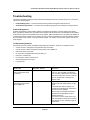
Troubleshooting .................................................................................................................. 338
Page 9
TL-SG3109/TL-SL3428/TL-SL3452 Gigabit Managed Switch Family CLI Reference Guide
Section 1. Using the CLI
This chapter describes how to start using the CLI and describes implemented command editing features to assist
in using the CLI.
1.1
CLI Command Modes
1.1.1
Introduction
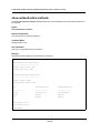
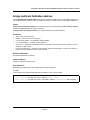
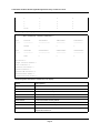
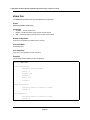
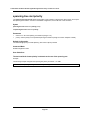
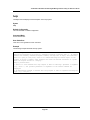
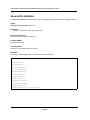
To assist in configuring the device, the Command Line Interface (CLI) is divided into different command modes.
Each command mode has its own set of specific commands. Entering a question mark "?" at the system prompt
(console prompt) displays a list of commands available for that particular command mode.
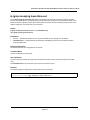
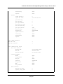
From each mode, a specific command is used to navigate from one command mode to another. The standard
order to access the modes is as follows: User EXEC mode, Privileged EXEC mode, Global Configuration mode,
and Interface Configuration mode. The following figure illustrates the command mode access path.
When starting a session, the initial mode is the User EXEC mode. Only a limited subset of commands is available
in User EXEC mode. This level is reserved for tasks that do not change the configuration. To enter the next level,
the Privileged EXEC mode, a password is required.
The Privileged EXEC mode gives access to commands that are restricted on User EXEC mode and provides
access to the device Configuration mode.
Page 10
TL-SG3109/TL-SL3428/TL-SL3452 Gigabit Managed Switch Family CLI Reference Guide
The Global Configuration mode manages the device configuration on a global level.
The Interface Configuration mode configures specific interfaces in the device.
1.1.2
User EXEC Mode
After logging into the device, the user is automatically in User EXEC command mode unless the user is defined as
a privileged user. In general, the User EXEC commands allow the user to perform basic tests, and list system
information.
The user-level prompt consists of the device host name followed by the angle bracket (>).
Console>
The default host name is Console unless it has been changed using the hostname command in the Global Configuration mode.
1.1.3
Privileged EXEC Mode
Privileged access is password protected to prevent unauthorized use because many of the privileged commands
set operating system parameters. The password is not displayed on the screen and is case sensitive.
Privileged users enter directly into the Privileged EXEC mode. To enter the Privileged EXEC mode from the User
EXEC mode, perform the following steps:
1.
2.
At the prompt enter the enable command and press <Enter>. A password prompt is displayed.
Enter the password and press <Enter>. The password is displayed as *. The Privileged EXEC mode prompt
is displayed. The Privileged EXEC mode prompt consists of the device host name followed by #.
Console#
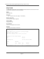
To return from the Privileged EXEC mode to the User EXEC mode, use the disable command. The following
example illustrates how to access the Privileged EXEC mode and return to the User EXEC mode:
Console> enable
Enter Password: ******
Console#
Console# disable
Console>
The exit command is used to return from any mode to the previous mode except when returning to the User
EXEC mode from the Privileged EXEC mode. For example, the exit command is used to return from the Interface
Configuration mode to the Global Configuration mode.
Page 11
TL-SG3109/TL-SL3428/TL-SL3452 Gigabit Managed Switch Family CLI Reference Guide
1.1.4
Global Configuration Mode
Global Configuration mode commands apply to features that affect the system as a whole, rather than just a specific interface. The configure Privileged EXEC mode command is used to enter the Global Configuration mode.
To enter the Global Configuration mode perform the following steps:
1.
At the Privileged EXEC mode prompt enter the configure command and press <Enter>. The Global Configuration mode prompt is displayed. The Global Configuration mode prompt consists of the device host name
followed by (config) and #.
Console(config)#
To return from the Global Configuration mode to the Privileged EXEC mode, the user can use one of the following
commands:
•
•
•
exit
end
<Ctrl+Z>
The following example illustrates how to access the Global Configuration mode and return to the Privileged EXEC
mode:
Console#
Console# configure
Console(config)# exit
Console#
1.1.5
Interface Configuration and Specific Configuration Modes
Interface Configuration mode commands modify specific interface operations. The following are the Interface Configuration modes:
•
•
•
•
•
•
•
Line Interface — Contains commands to configure the management connections. These include commands
such as line timeout settings, etc. The line Global Configuration mode command is used to enter the Line
Configuration command mode.
VLAN Database — Contains commands to create a VLAN as a whole. The vlan database Global Configuration mode command is used to enter the VLAN Database Interface Configuration mode.
Management Access List — Contains commands to define management access-lists. The management
access-list Global Configuration mode command is used to enter the Management Access List Configuration
mode.
Ethernet — Contains commands to manage port configuration. The interface ethernet Global Configuration
mode command is used to enter the Interface Configuration mode to configure an Ethernet type interface.
Port Channel — Contains commands to configure port-channels, for example, assigning ports to a portchannel. Most of these commands are the same as the commands in the Ethernet interface mode, and are
used to manage the member ports as a single entity. The interface port-channel Global Configuration mode
command is used to enter the Port Channel Interface Configuration mode.
SSH Public Key-chain — Contains commands to manually specify other device SSH public keys. The
crypto key pubkey-chain ssh Global Configuration mode command is used to enter the SSH Public Keychain Configuration mode.
QoS — Contains commands related to service definitions. The qos Global Configuration mode command is
used to enter the QoS services configuration mode.
Page 12
TL-SG3109/TL-SL3428/TL-SL3452 Gigabit Managed Switch Family CLI Reference Guide
•
MAC Access-List — Configures conditions required to allow traffic based on MAC addresses. The mac
access-list Global Configuration mode command is used to enter the MAC access-list configuration mode..
1.2
Starting the CLI
The device can be managed over a direct connection to the device console port or via a Telnet connection. The
device is managed by entering command keywords and parameters at the prompt. Using the device commandline interface (CLI) is very similar to entering commands on a UNIX system.
If access is via a Telnet connection, ensure that the device has a defined IP address, corresponding management
access is granted, and the workstation used to access the device is connected to the device prior to using CLI
commands.
Note
The following steps are for use on the console line only.
To start using the CLI, perform the following steps:
1.
Connect the DB9 null-modem or cross over cable to the RS-232 serial port of the device to the RS-232 serial
port of the terminal or computer running the terminal emulation application.
Note
The default data rate is 38400.
a) Set the data format to 8 data bits, 1 stop bit, and no parity.
b) Set Flow Control to none.
c) Under Properties, select VT100 for Emulation mode.
d) Select Terminal keys for Function, Arrow, and Ctrl keys. Ensure that the setting is for Terminal keys
(not Windows keys).
Note
When using HyperTerminal with Microsoft® Windows 2000,ensure that Windows® 2000 Service Pack 2
or later is installed.With Windows 2000 Service Pack 2, the arrow keys function properly in
HyperTerminal’s VT100 emulation. Go to www.microsoft.com for information on Windows 2000 service
packs.
2.
Enter the following commands to begin the configuration procedure:
Console> enable
Console# configure
Console(config)#
3.
4.
Configure the device and enter the necessary commands to complete the required tasks.
When finished, exit the session with the exit command.
When a different user is required to log onto the system, use the login Privileged EXEC mode command. This
effectively logs off the current user and logs on the new user.
Page 13
TL-SG3109/TL-SL3428/TL-SL3452 Gigabit Managed Switch Family CLI Reference Guide
1.3
Editing Features
1.3.1
Entering Commands
A CLI command is a series of keywords and arguments. Keywords identify a command, and arguments specify
configuration parameters. For example, in the command show interfaces status ethernet e8, show, interfaces
and status are keywords, ethernet is an argument that specifies the interface type, and 8 specifies the port.
To enter commands that require parameters, enter the required parameters after the command keyword. For
example, to set a password for the administrator, enter:
Console(config)# username admin password smith
When working with the CLI, the command options are not displayed. The command is not selected from a menu,
but is manually entered. To see what commands are available in each mode or within an interface configuration,
the CLI does provide a method of displaying the available commands, the command syntax requirements and in
some instances parameters required to complete the command. The standard command to request help is ?.
There are two instances where help information can be displayed:
•
Keyword lookup — The character ? is entered in place of a command. A list of all valid commands and corresponding help messages are is displayed.
•
Partial keyword lookup — If a command is incomplete and or the character ? is entered in place of a
parameter. The matched keyword or parameters for this command are displayed.
To assist in using the CLI, there is an assortment of editing features. The following features are described:
•
•
•
Terminal Command Buffer
Command Completion
Keyboard Shortcuts
1.3.1.1
Terminal Command Buffer
Every time a command is entered in the CLI, it is recorded on an internally managed Command History buffer.
Commands stored in the buffer are maintained on a First In First Out (FIFO) basis. These commands can be
recalled, reviewed, modified, and reissued. This buffer is not preserved across device resets.
K ey wo r d
De scr ip t io n
Up-arrow key
Ctrl+P
Recalls commands in the history buffer, beginning with the most recent command. Repeats the key sequence to recall successively older commands.
Down-arrow key
Returns to more recent commands in the history buffer after recalling commands with the up-arrow key. Repeating the key sequence will recall successively more recent commands.
By default, the history buffer system is enabled, but it can be disabled at any time. For information about the command syntax to enable or disable the history buffer, see history.
There is a standard default number of commands that are stored in the buffer. The standard number of 10 commands can be increased to 216. By configuring 0, the effect is the same as disabling the history buffer system. For
information about the command syntax for configuring the command history buffer, see history size.
To display the history buffer, see show history.
Page 14
TL-SG3109/TL-SL3428/TL-SL3452 Gigabit Managed Switch Family CLI Reference Guide
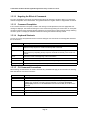
1.3.1.2
Negating the Effect of Commands
For many configuration commands, the prefix keyword no can be entered to cancel the effect of a command or
reset the configuration to the default value. This guide describes the negation effect for all applicable commands.
1.3.1.3
Command Completion
If the command entered is incomplete, invalid or has missing or invalid parameters, then the appropriate error
message is displayed. This assists in entering the correct command. By pressing the <Tab> button, an incomplete
command is entered. If the characters already entered are not enough for the system to identify a single matching
command, press ? to display the available commands matching the characters already entered.
1.3.1.4
Keyboard Shortcuts
The CLI has a range of keyboard shortcuts to assist in editing the CLI commands. The following table describes
the CLI shortcuts.
Key bo ard Ke y
D escr ip tio n
Up-arrow key
Recalls commands from the history buffer, beginning with the most recent command.
Repeat the key sequence to recall successively older commands.
Down-arrow key
Returns the most recent commands from the history buffer after recalling commands with
the up arrow key. Repeating the key sequence will recall successively more recent commands.
Ctrl+A
Moves the cursor to the beginning of the command line.
Ctrl+E
Moves the cursor to the end of the command line.
Ctrl+Z / End
Returns back to the Privileged EXEC mode from any configuration mode.
Backspace key
Deletes one character left to the cursor position.
1.3.1.5
CLI Command Conventions
When entering commands there are certain command entry standards that apply to all commands. The following
table describes the command conventions.
Con ve nti on
Desc ri pti on
[]
In a command line, square brackets indicates an optional entry.
{}
In a command line, curly brackets indicate a selection of compulsory parameters separated by the | character. One option must be selected. For example: flowcontrol
{auto|on|off} means that for the flowcontrol command either auto, on or off must be
selected.
Italic font
Indicates a parameter.
<Enter>
Any individual key on the keyboard. For example click <Enter>.
Ctrl+F4
Any combination keys pressed simultaneously on the keyboard.
Page 15
TL-SG3109/TL-SL3428/TL-SL3452 Gigabit Managed Switch Family CLI Reference Guide
Screen Display
Indicates system messages and prompts appearing on the console.
all
When a parameter is required to define a range of ports or parameters and all is an
option, the default for the command is all when no parameters are defined. For example, the command interface range port-channel has the option of either entering a
range of channels, or selecting all. When the command is entered without a parameter,
it automatically defaults to all.
_______________________________________________________________________________________
Page 16
TL-SG3109/TL-SL3428/TL-SL3452 Gigabit Managed Switch Family CLI Reference Guide
Section 2. AAA Commands
aaa authentication login
The aaa authentication login Global Configuration mode command defines login authentication. To return to the
default configuration, use the no form of this command.
Syntax
aaa authentication login {default | list-name} method1 [method2...]
no aaa authentication login {default | list-name}
Parameters
default — Uses the listed authentication methods that follow this argument as the default list of methods
•
•
•
when a user logs in.
list-name — Character string used to name the list of authentication methods activated when a user logs in.
(Range: 1-12 characters).
method1 [method2...] — Specify at least one from the following table:
K ey wo r d
De scri p ti o n
enable
Uses the enable password for authentication.
line
Uses the line password for authentication.
local
Uses the local username database for authentication.
none
Uses no authentication.
radius
Uses the list of all RADIUS servers for authentication.
Default Configuration
The local user database is checked. This has the same effect as the command aaa authentication login listname local.
Note
On the console, login succeeds without any authentication check if the authentication method is not
defined.
Command Mode
Global Configuration mode
Page 17
TL-SG3109/TL-SL3428/TL-SL3452 Gigabit Managed Switch Family CLI Reference Guide
User Guidelines
The default and optional list names created with the aaa authentication login command are used with the login
authentication command.
Create a list by entering the aaa authentication login list-name method command for a particular protocol, where
list-name is any character string used to name this list. The method argument identifies the list of methods that the
authentication algorithm tries, in the given sequence.
The additional methods of authentication are used only if the previous method returns an error, not if it fails. To
ensure that the authentication succeeds even if all methods return an error, specify none as the final method in
the command line.
Example
The following example configures the authentication login.
Console(config)# aaa authentication login default radius local enable none
Page 18
TL-SG3109/TL-SL3428/TL-SL3452 Gigabit Managed Switch Family CLI Reference Guide
aaa authentication enable
The aaa authentication enable Global Configuration mode command defines authentication method lists for
accessing higher privilege levels. To return to the default configuration, use the no form of this command.
Syntax
aaa authentication enable {default | list-name} method1 [method2...]
no aaa authentication enable {default | list-name}
Parameters
default — Uses the listed authentication methods that follow this argument as the default list of methods,
•
•
•
when using higher privilege levels.
list-name — Character string used to name the list of authentication methods activated, when using access
higher privilege levels (Range: 1-12 characters).
method1 [method2...] — Specify at least one from the following table:
K ey wo r d
De scri p ti o n
enable
Uses the enable password for authentication.
line
Uses the line password for authentication.
none
Uses no authentication.
radius
Uses the list of all RADIUS servers for authentication. Uses username $enabx$.,
where x is the privilege level.
Default Configuration
If the default list is not set, only the enable password is checked. This has the same effect as the command aaa
authentication enable default enable.
On the console, the enable password is used if it exists. If no password is set, the process still succeeds. This has
the same effect as using the command aaa authentication enable default enable none.
Command Mode
Global Configuration mode
User Guidelines
The default and optional list names created with the aaa authentication enable command are used with the
enable authentication command.
The additional methods of authentication are used only if the previous method returns an error, not if it fails. To
ensure that the authentication succeeds even if all methods return an error, specify none as the final method in
the command line.
All aaa authentication enable default requests sent by the device to a RADIUS server include the username
$enabx$., where x is the requested privilege level.
Page 19
TL-SG3109/TL-SL3428/TL-SL3452 Gigabit Managed Switch Family CLI Reference Guide
Example
The following example sets the enable password for authentication when accessing higher privilege levels.
Console(config)# aaa authentication enable default enable
Page 20
TL-SG3109/TL-SL3428/TL-SL3452 Gigabit Managed Switch Family CLI Reference Guide
login authentication
The login authentication Line Configuration mode command specifies the login authentication method list for a
remote telnet or console. To return to the default configuration specified by the aaa authentication login command, use the no form of this command.
Syntax
login authentication {default | list-name}
no login authentication
Parameters
default — Uses the default list created with the aaa authentication login command.
•
•
list-name — Uses the indicated list created with the aaa authentication login command.
Default Configuration
Uses the default set with the command aaa authentication login.
Command Mode
Line Configuration mode
User Guidelines
Changing login authentication from default to another value may disconnect the telnet session.
Example
The following example specifies the default authentication method for a console.
Console(config)# line console
Console(config-line)# login authentication default
Page 21
TL-SG3109/TL-SL3428/TL-SL3452 Gigabit Managed Switch Family CLI Reference Guide
enable authentication
The enable authentication Line Configuration mode command specifies the authentication method list when
accessing a higher privilege level from a remote telnet or console. To return to the default configuration specified
by the aaa authentication enable command, use the no form of this command.
Syntax
enable authentication {default | list-name}
no enable authentication
Parameters
default — Uses the default list created with the aaa authentication enable command.
•
•
list-name — Uses the indicated list created with the aaa authentication enable command.
Default Configuration
Uses the default set with the aaa authentication enable command.
Command Mode
Line Configuration mode
User Guidelines
There are no user guidelines for this command.
Example
The following example specifies the default authentication method when accessing a higher privilege level from a
console.
Console(config)# line console
Console(config-line)# enable authentication default
Page 22
TL-SG3109/TL-SL3428/TL-SL3452 Gigabit Managed Switch Family CLI Reference Guide
ip http authentication
The ip http authentication Global Configuration mode command specifies authentication methods for HTTP
server users. To return to the default configuration, use the no form of this command.
Syntax
ip http authentication method1 [method2...]
no ip http authentication
Parameters
method1 [method2...] — Specify at least one from the following table:
•
Key wo rd
Des cription
local
Uses the local username database for authentication.
none
Uses no authentication.
radius
Uses the list of all RADIUS servers for authentication.
Default Configuration
The local user database is checked. This has the same effect as the command ip http authentication local.
Command Mode
Global Configuration mode
User Guidelines
The additional methods of authentication are used only if the previous method returns an error, not if it fails. To
ensure that the authentication succeeds even if all methods return an error, specify none as the final method in
the command line.
Example
The following example configures the HTTP authentication.
Console(config)# ip http authentication radius local
Page 23
TL-SG3109/TL-SL3428/TL-SL3452 Gigabit Managed Switch Family CLI Reference Guide
ip https authentication
The ip https authentication Global Configuration mode command specifies authentication methods for HTTPS
server users. To return to the default configuration, use the no form of this command.
Syntax
ip https authentication method1 [method2...]
no ip https authentication
Parameters
method1 [method2...] — Specify at least one from the following table:
•
Key wo rd
Sou rce o r de stin ati on
local
Uses the local username database for authentication.
none
Uses no authentication.
radius
Uses the list of all RADIUS servers for authentication.
Default Configuration
The local user database is checked. This has the same effect as the command ip https authentication local.
Command Mode
Global Configuration mode
User Guidelines
The additional methods of authentication are used only if the previous method returns an error, not if it fails. To
ensure that the authentication succeeds even if all methods return an error, specify none as the final method in
the command line.
Example
The following example configures HTTPS authentication.
Console(config)# ip https authentication radius local
Page 24
TL-SG3109/TL-SL3428/TL-SL3452 Gigabit Managed Switch Family CLI Reference Guide
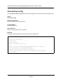
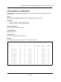
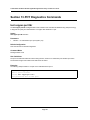
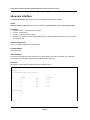
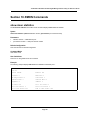
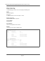
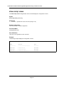
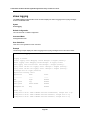
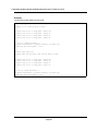
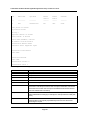
show authentication methods
The show authentication methods Privileged EXEC mode command displays information about the authentication methods.
Syntax
show authentication methods
Default Configuration
This command has no default configuration.
Command Mode
Privileged EXEC mode
User Guidelines
There are no user guidelines for this command.
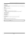
Example
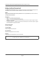
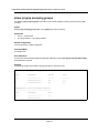
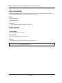
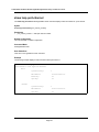
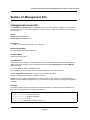
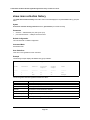
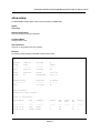
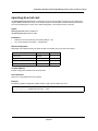
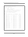
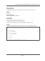
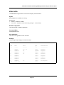
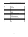
The following example displays the authentication configuration.
Console# show authentication methods
Login Authentication Method Lists
--------------------------------Default: Radius, Local, Line
Console_Login: Line, None
Enable Authentication Method Lists
---------------------------------Default: Radius, Enable
Console_Enable: Enable, None
Line
Login Method List
Enable Method List
--------------
-----------------
------------------
Console
Console_Login
Console_Enable
Telnet
Default
Default
SSH
Default
Default
http: Radius, Local
https: Radius, Local
dot1x: Radius
Page 25
TL-SG3109/TL-SL3428/TL-SL3452 Gigabit Managed Switch Family CLI Reference Guide
password
The password Line Configuration mode command specifies a password on a line. To remove the password, use
the no form of this command.
Syntax
password password [encrypted]
no password
Parameters
password — Password for this level (Range: 1-159 characters).
•
•
encrypted — Encrypted password to be entered, copied from another device configuration.
Default Configuration
No password is defined.
Command Mode
Line Configuration mode
User Guidelines
If a password is defined as encrypted, the required password length is 32 characters.
Example
The following example specifies password secret on a console.
Console(config)# line console
Console(config-line)# password secret
Page 26
TL-SG3109/TL-SL3428/TL-SL3452 Gigabit Managed Switch Family CLI Reference Guide
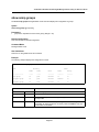
enable password
The enable password Global Configuration mode command sets a local password to control access to user and
privilege levels. To remove the password requirement, use the no form of this command.
Syntax
enable password [level level] password [encrypted]
no enable password [level level]
Parameters
password — Password for this level (Range: 1-159 characters).
•
•
level — Level for which the password applies. If not specified the level is 15
•
(Range: 1-15).
encrypted — Encrypted password entered, copied from another device configuration.
Default Configuration
No enable password is defined.
Command Mode
Global Configuration mode
User Guidelines
There are no user guidelines for this command.
Example
The following example sets local level 15 password secret to control access to user and privilege levels.
Console(config)# enable password level 15 secret
Page 27
TL-SG3109/TL-SL3428/TL-SL3452 Gigabit Managed Switch Family CLI Reference Guide
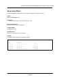
username
The username Global Configuration mode command creates a user account in the local database. To remove a
user name, use the no form of this command.
Syntax
username name [password password] [level level] [encrypted]
no username name
Parameters
name — The name of the user (Range: 1- 20 characters).
•
•
password — The authentication password for the user (Range: 1-159 characters).
•
level — The user level (Range: 1-15).
•
encrypted — Encrypted password entered, copied from another device configuration.
Default Configuration
No user is defined.
Command Mode
Global Configuration mode
User Guidelines
User account can be created without a password.
Example
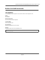
The following example configures user bob with password lee and user level 15 to the system.
Console(config)# username bob password lee level 15
Page 28
TL-SG3109/TL-SL3428/TL-SL3452 Gigabit Managed Switch Family CLI Reference Guide
Section 3. Address Table Commands
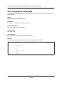
bridge address
The bridge address Interface Configuration (VLAN) mode command adds a MAC-layer station source address to
the bridge table. To delete the MAC address, use the no form of this command.
Syntax
bridge address mac-address {ethernet interface | port-channel port-channel-number} [permanent | delete-onreset | delete-on-timeout | secure]
no bridge address [mac-address]
Parameters
mac-address — A valid MAC address.
•
•
interface — A valid Ethernet port.
•
port-channel-number — A valid port-channel number.
•
permanent — The address can only be deleted by the no bridge address command.
•
delete-on-reset — The address is deleted after reset.
•
delete-on-timeout — The address is deleted after "age out" time has expired.
•
secure — The address is deleted after the port changes mode to unlock learning (no port security command). This parameter is only available when the port is in the learning locked mode.
Default Configuration
No static addresses are defined. The default mode for an added address is permanent.
Command Mode
Interface Configuration (VLAN) mode
User Guidelines
Using the no form of the command without specifying a MAC address deletes all static MAC addresses belonging
to this VLAN).
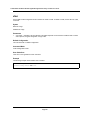
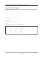
Example
The following example adds a permanent static MAC-layer station source address 3aa2.64b3.a245 on port 7 to
the bridge table.
Console(config)# interface vlan 2
Console(config-if)# bridge address 3aa2.64b3.a245 ethernet e7 permanent
Page 29
TL-SG3109/TL-SL3428/TL-SL3452 Gigabit Managed Switch Family CLI Reference Guide
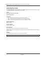
bridge multicast filtering
The bridge multicast filtering Global Configuration mode command enables filtering multicast addresses. To disable filtering multicast addresses, use the no form of this command.
Syntax
bridge multicast filtering
no bridge multicast filtering
Default Configuration
Filtering multicast addresses is disabled. All multicast addresses are flooded to all ports.
Command Mode
Global Configuration mode
User Guidelines
If multicast routers exist on the VLAN, do not change the unregistered multicast addresses state to drop on the
switch ports.
If multicast routers exist on the VLAN and IGMP-snooping is not enabled, the bridge multicast forward-all command should be used to enable forwarding all multicast packets to the multicast switches.
Example
In this example, bridge multicast filtering is enabled.
Console(config)# bridge multicast filtering
Page 30
TL-SG3109/TL-SL3428/TL-SL3452 Gigabit Managed Switch Family CLI Reference Guide
bridge multicast address
The bridge multicast address Interface Configuration (VLAN) mode command registers a MAC-layer multicast
address in the bridge table and statically adds ports to the group. To unregister the MAC address, use the no form
of this command.
Syntax
bridge multicast address {mac-multicast-address | ip-multicast-address}
bridge multicast address {mac-multicast-address | ip-multicast-address} [add | remove] {ethernet interface-list
| port-channel port-channel-number-list}
no bridge multicast address {mac-multicast-address | ip-multicast-address}
Parameters
add — Adds ports to the group. If no option is specified, this is the default option.
•
•
remove — Removes ports from the group.
•
mac-multicast-address — A valid MAC multicast address.
•
ip- multicast-address — A valid IP multicast address.
•
interface-list — Separate nonconsecutive Ethernet ports with a comma and no spaces; a hyphen is used to
•
designate a range of ports.
port-channel-number-list — Separate nonconsecutive port-channels with a comma and no spaces; a hyphen
is used to designate a range of ports.
Default Configuration
No multicast addresses are defined.
Command Mode
Interface configuration (VLAN) mode
User Guidelines
If the command is executed without add or remove, the command only registers the group in the bridge database.
Static multicast addresses can only be defined on static VLANs.
Examples
The following example registers the MAC address:
Console(config)# interface vlan 8
Console(config-if)# bridge multicast address 01:00:5e:02:02:03
The following example registers the MAC address and adds ports statically.
Console(config)# interface vlan 8
Console(config-if)# bridge multicast address 01:00:5e:02:02:03 add ethernet e1-4, e7
Page 31
TL-SG3109/TL-SL3428/TL-SL3452 Gigabit Managed Switch Family CLI Reference Guide
bridge multicast forbidden address
The bridge multicast forbidden address Interface Configuration (VLAN) mode command forbids adding a specific multicast address to specific ports. Use the no form of this command to return to the default configuration.
Syntax
bridge multicast forbidden address {mac-multicast-address | ip-multicast-address} {add | remove} {ethernet
interface-list | port-channel port-channel-number-list}
no bridge multicast forbidden address {mac-multicast-address | ip-multicast-address}
Parameters
add — Adds ports to the group.
•
•
remove — Removes ports from the group.
•
mac-multicast-address — A valid MAC multicast address.
•
ip- multicast-address — A valid IP multicast address.
•
interface-list — Separate nonconsecutive Ethernet ports with a comma and no spaces; hyphen is used to
•
designate a range of ports.
port-channel-number-list — Separate nonconsecutive valid port-channels with a comma and no spaces; a
hyphen is used to designate a range of port-channels.
Default Configuration
No forbidden addresses are defined.
Command Modes
Interface Configuration (VLAN) mode
User Guidelines
Before defining forbidden ports, the multicast group should be registered.
Examples
In this example, MAC address 0100.5e02.0203 is forbidden on port 7 within VLAN 8.
Console(config)# interface vlan 8
Console(config-if)# bridge multicast address 0100.5e.02.0203
Console(config-if)# bridge multicast forbidden address 0100.5e02.0203 add ethernet e7
Page 32
TL-SG3109/TL-SL3428/TL-SL3452 Gigabit Managed Switch Family CLI Reference Guide
bridge multicast forward-all
The bridge multicast forward-all Interface Configuration (VLAN) mode command enables forwarding all multicast packets on a port. To restore the default configuration, use the no form of this command.
Syntax
bridge multicast forward-all {add | remove} {ethernet interface-list | port-channel port-channel-number-list}
no bridge multicast forward-all
Parameters
add — Force forwarding all multicast packets.
•
•
remove — Do not force forwarding all multicast packets.
•
interface-list — Separate nonconsecutive Ethernet ports with a comma and no spaces; a hyphen is used to
•
designate a range of ports.
port-channel-number-list — Separate nonconsecutive port-channels with a comma and no spaces; a hyphen
is used to designate a range of port-channels.
Default Configuration
This setting is disabled.
Command Mode
Interface Configuration (VLAN) mode
User Guidelines
There are no user guidelines for this command.
Example
In this example, all multicast packets on port 8 are forwarded.
Console(config)# interface vlan 2
Console(config-if)# bridge multicast forward-all add ethernet e8
Page 33
TL-SG3109/TL-SL3428/TL-SL3452 Gigabit Managed Switch Family CLI Reference Guide
bridge multicast forbidden forward-all
The bridge multicast forbidden forward-all Interface Configuration (VLAN) mode command forbids a port to be
a forward-all-multicast port. To restore the default configuration, use the no form of this command.
Syntax
bridge multicast forbidden forward-all {add | remove} {ethernet interface-list | port-channel port-channelnumber-list}
no bridge multicast forbidden forward-all
Parameters
add — Forbids forwarding all multicast packets.
•
•
remove — Does not forbid forwarding all multicast packets.
•
interface-list — Separates nonconsecutive Ethernet ports with a comma and no spaces; a hyphen is used to
•
designate a range of ports.
port-channel-number-list — Separates nonconsecutive port-channels with a comma and no spaces; a
hyphen is used to designate a range of port-channels.
Default Configuration
This setting is disabled.
Command Mode
Interface Configuration (VLAN) mode
User Guidelines
IGMP snooping dynamically discovers multicast router ports. When a multicast router port is discovered, all the
multicast packets are forwarded to it unconditionally.
This command prevents a port from becoming a multicast router port.
Example
In this example, forwarding all multicast packets to port 1 with VLAN 2 is forbidden.
Console(config)# interface vlan 2
Console(config-if)# bridge multicast forbidden forward-all add ethernet e1
Page 34
TL-SG3109/TL-SL3428/TL-SL3452 Gigabit Managed Switch Family CLI Reference Guide
bridge aging-time
The bridge aging-time Global Configuration mode command sets the address table aging time. To restore the
default configuration, use the no form of this command.
Syntax
bridge aging-time seconds
no bridge aging-time
Parameters
seconds — Time in seconds. (Range: 10-630 seconds)
•
Default Configuration
The default setting is 300 seconds.
Command Mode
Global Configuration mode
User Guidelines
There are no user guidelines for this command.
Example
In this example the bridge aging time is set to 250.
Console(config)# bridge aging-time 250
Page 35
TL-SG3109/TL-SL3428/TL-SL3452 Gigabit Managed Switch Family CLI Reference Guide
clear bridge
The clear bridge Privileged EXEC mode command removes any learned entries from the forwarding database.
Syntax
clear bridge
Default Configuration
This command has no default configuration.
Command Mode
Privileged EXEC mode
User Guidelines
There are no user guidelines for this command.
Example
In this example, the bridge tables are cleared.
Console# clear bridge
Page 36
TL-SG3109/TL-SL3428/TL-SL3452 Gigabit Managed Switch Family CLI Reference Guide
port security
The port security Interface Configuration mode command locks the port, thereby, blocking unknown traffic and
preventing the port from learning new addresses. To return to the default configuration, use the no form of this
command.
Syntax
port security [forward | discard | discard-shutdown] [trap seconds]
no port security
Parameters
forward — Forwards packets with unlearned source addresses, but does not learn the address.
•
•
discard — Discards packets with unlearned source addresses. This is the default if no option is indicated.
•
discard-shutdown — Discards packets with unlearned source addresses. The port is also shut down.
•
seconds — Sends SNMP traps and defines the minimum amount of time in seconds between consecutive
traps. (Range: 1-1000000)
Default Configuration
This setting is disabled.
Command Mode
Interface Configuration (Ethernet, port-channel) mode
User Guidelines
There are no user guidelines for this command.
Example
In this example, port 1 forwards all packets without learning addresses of packets from unknown sources and
sends traps every 100 seconds if a packet with an unknown source address is received.
Console(config)# interface ethernet e1
Console(config-if)# port security forward trap 100
Page 37
TL-SG3109/TL-SL3428/TL-SL3452 Gigabit Managed Switch Family CLI Reference Guide
port security routed secure-address
The port security routed secure-address Interface Configuration (Ethernet, port-channel) mode command adds
a MAC-layer secure address to a routed port. Use the no form of this command to delete a MAC address.
Syntax
port security routed secure-address mac-address
no port security routed secure-address mac-address
Parameters
mac-address — A valid MAC address.
•
Default Configuration
No addresses are defined.
Command Mode
Interface Configuration (Ethernet, port-channel) mode. Cannot be configured for a range of interfaces (range context).
User Guidelines
The command enables adding secure MAC addresses to a routed port in port security mode. The command is
available when the port is a routed port and in port security mode. The address is deleted if the port exits the security mode or is not a routed port.
Example
In this example, the MAC-layer address 66:66:66:66:66:66 is added to port 1.
Console(config)# interface ethernet e1
Console(config-if)# port security routed secure-address 66:66:66:66:66:66
Page 38
TL-SG3109/TL-SL3428/TL-SL3452 Gigabit Managed Switch Family CLI Reference Guide
show bridge address-table
Use the show bridge address-table Privileged EXEC command to view entries in the bridge-forwarding database.
Syntax
show bridge address-table [vlan vlan] [ethernet interface | port-channel port-channel-number] ] [address macaddress]
Parameters
vlan — Specific VLAN, such as VLAN 1.
•
•
interface — Ethernet port.
•
port-channel-number — Port-channel number.
•
mac-address— MAC address.
Parameters Range
Default Configuration
This command has no default configuration.
Command Mode
Privileged EXEC
User Guidelines
Internal usage VLANs (VLANs that are automatically allocated on routed ports) are presented in the VLAN column
by a port number and not by a VLAN ID.
Example
Console# show bridge address-table
Aging time is 300 sec
vlan
mac address
Port
Type
---------
--------------
----
-------
3
00:00:00:55:55:66
3
dynamic
3
00:03:47:cc:01:ce
3
dynamic
3
00:06:1b:c9:6f:c5
3
dynamic
3
00:11:11:6b:3a:32
3
dynamic
3
00:80:92:0b:80:80
3
dynamic
Page 39
TL-SG3109/TL-SL3428/TL-SL3452 Gigabit Managed Switch Family CLI Reference Guide
show bridge address-table static
The show bridge address-table static Privileged EXEC mode command displays statically created entries in the
bridge-forwarding database.
Syntax
show bridge address-table static [vlan vlan] [ethernet interface | port-channel port-channel-number]
Parameters
vlan — Specifies a valid VLAN, such as VLAN 1.
•
•
interface — A valid Ethernet port.
•
port-channel-number — A valid port-channel number.
Default Configuration
This command has no default configuration.
Command Mode
Privileged EXEC mode
User Guidelines
There are no user guidelines for this command.
Example
In this example, all static entries in the bridge-forwarding database are displayed.
Console# show bridge address-table static
Aging time is 300 sec
vlan
mac address
port
type
----
-----------------
----
-----------------
1
00:60:70:4C:73:FF
8
Permanent
1
00:60.70.8C.73:FF
8
delete-on-timeout
200
00:10:0D:48:37:FF
9
delete-on-reset
Page 40
TL-SG3109/TL-SL3428/TL-SL3452 Gigabit Managed Switch Family CLI Reference Guide
show bridge address-table count
The show bridge address-table count Privileged EXEC mode command displays the number of addresses
present in the Forwarding Database.
Syntax
show bridge address-table count [vlan vlan][ ethernet interface-number | port-channel port-channel-number]
Parameters
vlan — Specifies a valid VLAN, such as VLAN 1.
•
•
interface — A valid Ethernet port.
•
port-channel-number — A valid port-channel number.
Default Configuration
This command has no default configuration.
Command Mode
Privileged EXEC mode
User Guidelines
There are no user guidelines for this command.
Example
In this example, the number of addresses present in all VLANs are displayed.
Console# show bridge address-table count
Capacity: 8192
Free: 8083
Used: 109
Secure addresses: 2
Static addresses: 1
Dynamic addresses: 97
Internal addresses: 9
Page 41
TL-SG3109/TL-SL3428/TL-SL3452 Gigabit Managed Switch Family CLI Reference Guide
show bridge multicast address-table
The show bridge multicast address-table User EXEC mode command displays multicast MAC address or IP
address table information.
Syntax
show bridge multicast address-table [vlan vlan-id] [address mac-multicast-address | ip-multicast-address]
[format ip | format mac]
Parameters
vlan-id — A valid VLAN ID value.
•
•
mac-multicast-address — A valid MAC multicast address.
•
ip-multicast-address — A valid IP multicast address.
•
format ip|mac — Multicast address format. Can be ip or mac. If the format is unspecified, the default is mac.
Default Configuration
This command has no default configuration.
Command Mode
Privileged EXEC mode
User Guidelines
A MAC address can be displayed in IP format only if it is in the range of 0100.5e00.0000-0100.5e7f.ffff.
Example
In this example, multicast MAC address and IP address table information is displayed.
Console# show bridge multicast address-table
Vlan
MAC Address
Type
Ports
----
--------------
-------
----------
1
01:00:5e:02:02:03
static
1, 2
18
01:00:5e:02:02:08
static
1-3
19
00:00:5e:02:02:08
dynamic
5-7
Forbidden ports for multicast addresses:
Vlan
MAC Address
Ports
----
--------------
-----
1
01:00:5e:02:02:03
8
19
01:00:5e:02:02:08
8
Page 42
TL-SG3109/TL-SL3428/TL-SL3452 Gigabit Managed Switch Family CLI Reference Guide
Console# show bridge multicast address-table format ip
Vlan
IP/MAC Address
Type
Ports
----
-----------------
------
---------
1
224-239.130|2.2.3
static
1,2
18
224-239.130|2.2.8
static
1-3
19
224-239.130|2.2.8
dynamic
5-7
Forbidden ports for multicast addresses:
Vlan
IP/MAC Address
Ports
----
-----------------
------
1
224-239.130|2.2.3
8
19
224-239.130|2.2.8
8
Note
A multicast MAC address maps to multiple IP addresses as shown above.
Page 43
TL-SG3109/TL-SL3428/TL-SL3452 Gigabit Managed Switch Family CLI Reference Guide
show bridge multicast filtering
The show bridge multicast filtering User EXEC mode command displays the multicast filtering configuration.
Syntax
show bridge multicast filtering vlan-id
Parameters
vlan-id — VLAN ID value.
•
Default Configuration
This command has no default configuration.
Command Mode
User EXEC mode
User Guidelines
There are no user guidelines for this command.
Example
In this example, the multicast configuration for VLAN 1 is displayed.
Console# show bridge multicast filtering 1
Filtering: Enabled
VLAN: 1
Port
Forward-Unregistered
Forward-All
Static
Status
Static
Status
----
---------
---------
---------
----------
1
Forbidden
Filter
Forbidden
Filter
2
Forward
Forward(s)
Forward
Forward(s)
3
-
Forward(d)
-
Forward(d)
Page 44
TL-SG3109/TL-SL3428/TL-SL3452 Gigabit Managed Switch Family CLI Reference Guide
show ports security
The show ports security Privileged EXEC mode command displays the port-lock status.
Syntax
show ports security [ethernet interface | port-channel port-channel-number]
Parameters
interface — A valid Ethernet port.
•
•
port-channel-number — A valid port-channel number.
Default Configuration
This command has no default configuration.
Command Mode
Privileged EXEC mode
User Guidelines
There are no user guidelines for this command.
Example
In this example, all classes of entries in the port-lock status are displayed:
Console# show ports security
Port
Action
Trap
Frequency
1
Disabled
-
-
2
Disabled
Discard
Disabled
-
3
Disabled
-
-
-
4
Disabled
-
-
-
5
Disqbled
-
-
-
6
Disabled
-
-
-
7
Disabled
-
-
-
8
Disabled
-
-
-
9
Disabled
-
-
-
10
Disabled
-
-
-
ch1
Disabled
ch2
Disabled
ch3
Disabled
ch4
Disabled
ch5
Disabled
ch6
Disabled
Page 45
TL-SG3109/TL-SL3428/TL-SL3452 Gigabit Managed Switch Family CLI Reference Guide
ch7
Disabled
ch8
Disabled
The following tables describes the fields shown above.
Field
Desc ription
Port
Port number
Status
Locked/Unlocked
Action
Action on violation
Trap
Indicates if traps are sent in case of a violation
Frequency
Minimum time between consecutive traps
Page 46
TL-SG3109/TL-SL3428/TL-SL3452 Gigabit Managed Switch Family CLI Reference Guide
Section 4. Clock
clock set
The clock set Privileged EXEC mode command manually sets the system clock.
Syntax
clock set hh:mm:ss day month year
or
clock set hh:mm:ss month day year
Parameters
hh:mm:ss — Current time in hours (military format), minutes, and seconds (hh: 0 - 23, mm: 0 - 59, ss: 0 - 59).
•
•
day — Current day (by date) in the month (1 - 31).
•
month — Current month using the first three letters by name (Jan, …, Dec).
•
year — Current year (2000 - 2097).
Default Configuration
This command has no default configuration.
Command Mode
Privileged EXEC mode
User Guidelines
There are no user guidelines for this command.
Example
The following example sets the system time to 13:32:00 on the 7th March 2002.
Console# clock set 13:32:00 7 Mar 2002
Page 47
TL-SG3109/TL-SL3428/TL-SL3452 Gigabit Managed Switch Family CLI Reference Guide
clock source
The clock source Global Configuration mode command configures an external time source for the system clock.
Use no form of this command to disable external time source.
Syntax
clock source {sntp}
no clock source
Parameters
sntp — SNTP servers
•
Default Configuration
No external clock source
Command Mode
Global Configuration mode
User Guidelines
There are no user guidelines for this command.
Examples
The following example configures an external time source for the system clock.
Console(config)# clock source sntp
Page 48
TL-SG3109/TL-SL3428/TL-SL3452 Gigabit Managed Switch Family CLI Reference Guide
clock timezone
The clock timezone Global Configuration mode command sets the time zone for display purposes. To set the
time to the Coordinated Universal Time (UTC), use the no form of this command.
Syntax
clock timezone hours-offset
no clock timezone
Parameters
hours-offset — Hours difference from UTC. (Range: -12 – +13)
•
Default Configuration
Clock set to UTC.
Command Mode
Global Configuration mode
User Guidelines
The system internally keeps time in UTC, so this command is used only for display purposes and when the time is
manually set.
Examples
The following example sets the timezone to 6 hours difference from UTC.
Console(config)# clock timezone -6 zone CST
Page 49
TL-SG3109/TL-SL3428/TL-SL3452 Gigabit Managed Switch Family CLI Reference Guide
clock summer-time
The clock summer-time Global Configuration mode command configures the system to automatically switch to
summer time (daylight saving time). To configure the software not to automatically switch to summer time, use the
no form of this command.
Syntax
clock summer-time recurring { | {week day month hh:mm week day month hh:mm}} [offset offset] [zone acronym]
clock summer-time date date month year hh:mm date month year hh:mm [offset offset] [zone acronym]
clock summer-time date month date year hh:mm month date year hh:mm [offset offset] [zone acronym]
no clock summer-time recurring
Parameters
recurring — Indicates that summer time should start and end on the corresponding specified days every
•
•
•
•
•
•
•
•
•
•
year.
date — Indicates that summer time should start on the first specific date listed in the command and end on
the second specific date in the command.
week — Week of the month. (Range: 1 - 5, first, last)
day — Day of the week (Range: first three letters by name, like sun)
date — Date of the month. (Range:1 - 31)
month — Month. (Range: first three letters by name, like Jan)
year — year - no abbreviation (Range: 2000 - 2097)
hh:mm — Time in military format, in hours and minutes. (Range: hh: 0 - 23, mm:0 - 59)
offset — Number of minutes to add during summer time. (Range: 1 - 1440)
acronym — The acronym of the time zone to be displayed when summer time is in effect. (Range: Up to 4
characters)
Default Configuration
Summer time is disabled.
offset — Default is 60 minutes.
acronym — If unspecified default to the timezone acronym.
If the timezone has not been defined, the default is UTC.
Command Mode
Global Configuration mode
Page 50
TL-SG3109/TL-SL3428/TL-SL3452 Gigabit Managed Switch Family CLI Reference Guide
User Guidelines
In both the date and recurring forms of the command, the first part of the command specifies when summer time
begins, and the second part specifies when it ends. All times are relative to the local time zone. The start time is
relative to standard time. The end time is relative to summer time. If the starting month is chronologically after the
ending month, the system assumes that you are in the southern hemisphere.
Examples
The following example sets summer time starting on the first Sunday in April at 2 am and finishing on the last Sunday in October at 2 am.
Console(config)# clock summer-time recurring first sun apr 2:00 last sun oct 2:00
Page 51
TL-SG3109/TL-SL3428/TL-SL3452 Gigabit Managed Switch Family CLI Reference Guide
sntp authentication-key
The sntp authentication-key Global Configuration mode command defines an authentication key for Simple Network Time Protocol (SNTP). To remove the authentication key for SNTP, use the no form of this command.
Syntax
sntp authentication-key number md5 value
no sntp authentication-key number
Parameters
number — Key number (Range: 1-4294967295)
•
•
value — Key value (Range: 1-8 characters)
Default Configuration
No authentication key is defined.
Command Mode
Global Configuration mode
User Guidelines
Multiple keys can be generated.
Examples
The following example defines the authentication key for SNTP.
Console(config)# sntp authentication-key 8 md5 ClkKey
Page 52
TL-SG3109/TL-SL3428/TL-SL3452 Gigabit Managed Switch Family CLI Reference Guide
sntp authenticate
The sntp authenticate Global Configuration mode command grants authentication for received Simple Network
Time Protocol (SNTP) traffic from servers. To disable the feature, use the no form of this command.
Syntax
sntp authenticate
no sntp authenticate
Default Configuration
No authentication
Command Mode
Global Configuration mode
User Guidelines
The command is relevant for both unicast and broadcast.
Examples
The following example defines the authentication key for SNTP and grants authentication.
Console(config)# sntp authentication-key 8 md5 ClkKey
Console(config)# sntp trusted-key 8
Console(config)# sntp authenticate
Page 53
TL-SG3109/TL-SL3428/TL-SL3452 Gigabit Managed Switch Family CLI Reference Guide
sntp trusted-key
The sntp trusted-key Global Configuration mode command authenticates the identity of a system to which Simple Network Time Protocol (SNTP) will synchronize. To disable authentication of the identity of the system, use the
no form of this command.
Syntax
sntp trusted-key key-number
no sntp trusted-key key-number
Parameters
key-number — Key number of authentication key to be trusted. (Range: 1 - 4294967295)
•
Default Configuration
No keys are trusted.
Command Mode
Global Configuration mode
User Guidelines
The command is relevant for both received unicast and broadcast.
If there is at least 1 trusted key, then unauthenticated messages will be ignored.
Examples
The following example authenticates key 8.
Console(config)# sntp authentication-key 8 md5 ClkKey
Console(config)# sntp trusted-key 8
Console(config)# sntp authenticate
Page 54
TL-SG3109/TL-SL3428/TL-SL3452 Gigabit Managed Switch Family CLI Reference Guide
sntp client poll timer
The sntp client poll timer Global Configuration mode command sets the polling time for the Simple Network
Time Protocol (SNTP) client. To return to default configuration, use the no form of this command.
Syntax
sntp client poll timer seconds
no sntp client poll timer
Parameters
seconds — Polling interval in seconds (Range: 60-86400)
•
Default Configuration
Polling interval is 1024 seconds.
Command Mode
Global Configuration mode
User Guidelines
There are no user guidelines for this command.
Examples
The following example sets the polling time for the Simple Network Time Protocol (SNTP) client to 120 seconds.
Console(config)# sntp client poll timer 120
Page 55
TL-SG3109/TL-SL3428/TL-SL3452 Gigabit Managed Switch Family CLI Reference Guide
sntp broadcast client enable
The sntp broadcast client enable Global Configuration mode command enables Simple Network Time Protocol
(SNTP) broadcast clients. To disable SNTP broadcast clients, use the no form of this command.
Syntax
sntp broadcast client enable
no sntp broadcast client enable
Default Configuration
The SNTP broadcast client is disabled.
Command Mode
Global Configuration mode
User Guidelines
Use the sntp client enable (Interface) Interface Configuration mode command to enable the SNTP client on a
specific interface.
Examples
The following example enables the SNTP broadcast clients.
Console(config)# sntp broadcast client enable
Page 56
TL-SG3109/TL-SL3428/TL-SL3452 Gigabit Managed Switch Family CLI Reference Guide
sntp anycast client enable
The sntp anycast client enable Global Configuration mode command enables SNTP anycast client. To disable
the SNTP anycast client, use the no form of this command.
Syntax
sntp anycast client enable
no sntp anycast client enable
Default Configuration
The SNTP anycast client is disabled.
Command Mode
Global Configuration mode
User Guidelines
Polling time is determined by the sntp client poll timer Global Configuration mode command.
Use the sntp client enable (Interface) Interface Configuration mode command to enable the SNTP client on a
specific interface.
Examples
The following example enables SNTP anycast clients.
console(config)# sntp anycast client enable
Page 57
TL-SG3109/TL-SL3428/TL-SL3452 Gigabit Managed Switch Family CLI Reference Guide
sntp client enable (Interface)
The sntp client enable Interface Configuration (Ethernet, port-channel, VLAN) mode command enables the Simple Network Time Protocol (SNTP) client on an interface. This applies to both receive broadcast and anycast
updates. To disable the SNTP client, use the no form of this command.
Syntax
sntp client enable
no sntp client enable
Default Configuration
The SNTP client is disabled on an interface.
Command Mode
Interface configuration (Ethernet, port-channel, VLAN) mode
User Guidelines
Use the sntp broadcast client enable Global Configuration mode command to enable broadcast clients globally.
Use the sntp anycast client enable Global Configuration mode command to enable anycast clients globally.
Examples
The following example enables the SNTP client on Ethernet port 3.
Console(config)# interface ethernet e3
Console(config-if)# sntp client enable
Page 58
TL-SG3109/TL-SL3428/TL-SL3452 Gigabit Managed Switch Family CLI Reference Guide
sntp unicast client enable
The sntp unicast client enable Global Configuration mode command enables the device to use the Simple Network Time Protocol (SNTP) to request and accept SNTP traffic from servers. To disable requesting and accepting
SNTP traffic from servers, use the no form of this command.
Syntax
sntp unicast client enable
no sntp unicast client enable
Default Configuration
The SNTP unicast client is disabled.
Command Mode
Global Configuration mode
User Guidelines
Use the sntp server Global Configuration mode command to define SNTP servers.
Examples
The following example enables the device to use the Simple Network Time Protocol (SNTP) to request and accept
SNTP traffic from servers.
Console(config)# sntp unicast client enable
Page 59
TL-SG3109/TL-SL3428/TL-SL3452 Gigabit Managed Switch Family CLI Reference Guide
sntp unicast client poll
The sntp unicast client poll Global Configuration mode command enables polling for the Simple Network Time
Protocol (SNTP) predefined unicast servers. To disable the polling for SNTP client, use the no form of this command.
Syntax
sntp unicast client poll
no sntp unicast client poll
Default Configuration
Polling is disabled.
Command Mode
Global Configuration mode
User Guidelines
Polling time is determined by the sntp client poll timer Global Configuration mode command.
Examples
The following example enables polling for Simple Network Time Protocol (SNTP) predefined unicast clients.
Console(config)# sntp unicast client poll
Page 60
TL-SG3109/TL-SL3428/TL-SL3452 Gigabit Managed Switch Family CLI Reference Guide
sntp server
The sntp server Global Configuration mode command configures the device to use the Simple Network Time
Protocol (SNTP) to request and accept SNTP traffic from a specified server. To remove a server from the list of
SNTP servers, use the no form of this command.
Syntax
sntp server {ip-address | hostname}[poll] [key keyid]
no sntp server host
Parameters
ip-address — IP address of the server.
•
•
hostname — Hostname of the server. (Range: 1-158 characters)
•
poll — Enable polling.
•
keyid — Authentication key to use when sending packets to this peer.
(Range:1-4294967295)
Default Configuration
No servers are defined.
Command Mode
Global Configuration mode
User Guidelines
Up to 8 SNTP servers can be defined.
Use the sntp unicast client enable Global Configuration mode command to enable predefined unicast clients
globally.
To enable polling you should also use the sntp unicast client poll Global Configuration mode command for global enabling.
Polling time is determined by the sntp client poll timer Global Configuration mode command.
Examples
The following example configures the device to accept SNTP traffic from the server on 192.1.1.1.
Console(config)# sntp server 192.1.1.1
Page 61
TL-SG3109/TL-SL3428/TL-SL3452 Gigabit Managed Switch Family CLI Reference Guide
show clock
The show clock User EXEC mode command displays the time and date from the system clock.
Syntax
show clock [detail]
Parameters
detail — Shows timezone and summertime configuration.
•
Default Configuration
This command has no default configuration.
Command Mode
User EXEC mode
User Guidelines
The symbol that precedes the show clock display indicates the following:
Symb ol
D escr ip tio n
*
Time is not authoritative.
(blank)
Time is authoritative.
.
Time is authoritative, but SNTP is not synchronized.
Example
The following example displays the time and date from the system clock.
Console> show clock
15:29:03 PDT(UTC-7) Jun 17 2002
Time source is SNTP
Console> show clock detail
15:29:03 PDT(UTC-7) Jun 17 2002
Time source is SNTP
Time zone:
Acronym is PST
Offset is UTC-8
Summertime:
Acronym is PDT
Recurring every year.
Begins at first Sunday of April at 2:00.
Ends at last Sunday of October at 2:00.
Offset is 60 minutes.
Page 62
TL-SG3109/TL-SL3428/TL-SL3452 Gigabit Managed Switch Family CLI Reference Guide
show sntp configuration
The show sntp configuration Privileged EXEC mode command shows the configuration of the Simple Network
Time Protocol (SNTP).
Syntax
show sntp configuration
Default Configuration
This command has no default configuration.
Command Mode
Privileged EXEC mode
User Guidelines
There are no user guidelines for this command.
Examples
The following example displays the current SNTP configuration of the device.
Console# show sntp configuration
Polling interval: 7200 seconds
MD5 Authentication keys: 8, 9
Authentication is required for synchronization.
Trusted Keys: 8, 9
Unicast Clients: Enabled
Unicast Clients Polling: Enabled
Server
Polling
Encryption Key
-----------
-------
--------------
176.1.1.8
Enabled
9
176.1.8.179
Disabled
Disabled
Broadcast Clients: Enabled
Anycast Clients: Enabled
Broadcast and Anycast Interfaces: 1, 3
Page 63
TL-SG3109/TL-SL3428/TL-SL3452 Gigabit Managed Switch Family CLI Reference Guide
show sntp status
The show sntp status Privileged EXEC mode command shows the status of the Simple Network Time Protocol
(SNTP).
Syntax
show sntp status
Default Configuration
This command has no default configuration.
Command Mode
Privileged EXEC mode
User Guidelines
There are no user guidelines for this command.
Examples
The following example shows the status of the SNTP.
Console# show sntp status
Clock is synchronized, stratum 4, reference is 176.1.1.8, unicast
Reference time is AFE2525E.70597B34 (00:10:22.438 PDT Jul 5 1993)
Unicast servers:
Server
Status
Last response
Offset
[mSec]
Delay
[mSec]
-----------
-------
----------------------------
------
------
176.1.1.8
Up
19:58:22.289 PDT Feb 19 2002
7.33
117.79
176.1.8.179
Unknown
12:17.17.987 PDT Feb 19 2002
8.98
189.19
Interface
Status
Offset
Delay
[mSec]
[mSec]
Anycast server:
Server
Last response
---------
-------
-----
-----------------------------
------
-----
176.1.11.8
VLAN 118
Up
9:53:21.789 PDT Feb 19 2002
7.19
119.89
Broadcast:
Interface
IP address
Last response
---------
---------
----------------------------
176.9.1.1
VLAN 119
19:17:59.792 PDT Feb 19 2002
Page 64
TL-SG3109/TL-SL3428/TL-SL3452 Gigabit Managed Switch Family CLI Reference Guide
Section 5. Configuration and Image Files
copy
The copy Privileged EXEC mode command copies files from a source to a destination.
Syntax
copy source-url destination-url
Parameters
source-url — The source file location URL or reserved keyword of the source file to be copied.
•
(Range: 1-160 characters)
destination-url — The destination file URL or reserved keyword of the destination file.
(Range: 1-160 characters)
The following table displays keywords and URL prefixes:
•
Key wo rd
Sou rce o r Desti na t io n
flash:
Source or destination URL for flash memory. It’s the default in case a URL is specified
without a prefix.
running-config
Represents the current running configuration file.
startup-config
Represents the startup configuration file.
image
If the source file, represents the active image file. If the destination file, represents the
non-active image file.
boot
Boot file.
tftp://
Source or destination URL for a TFTP network server. The syntax for this alias is tftp://
host/[directory]/filename. The host can be represented by its IP address or hostname.
xmodem:
Source for the file from a serial connection that uses the Xmodem protocol.
null:
Null destination for copies or files. A remote file can be copied to null to determine its size.
Default Configuration
This command has no default configuration.
Command Mode
Privileged EXEC mode
User Guidelines
Up to five backup configuration files are supported on the device.
The location of a file system dictates the format of the source or destination URL.
The entire copying process may take several minutes and differs from protocol to protocol and from network to
network.
Understanding Invalid Combinations of Source and Destination
Page 65
TL-SG3109/TL-SL3428/TL-SL3452 Gigabit Managed Switch Family CLI Reference Guide
Some invalid combinations of source and destination exist. Specifically, you cannot copy if one of the following
conditions exist:
The source file and destination file are the same file.
xmodem: is the destination file. The source file can be copied to image, boot and null: only.
tftp:// is the source file and destination file on the same copy.
The following table describes copy characters:
Cha rac ter
Desc ription
!
For network transfers, indicates that the copy process is taking place. Each exclamation
point indicates successful transfer of ten packets (512 bytes each).
.
For network transfers, indicates that the copy process timed out. Generally, many periods in a row means that the copy process may fail.
Copying an Image File from a Server to Flash Memory
To copy an image file from a server to flash memory, use the copy source-url image command.
Copying a Boot File from a Server to Flash Memory
To copy a boot file from a server to flash memory, enter the copy source-url boot command.
Copying a Configuration File from a Server to the Running Configuration File
To load a configuration file from a network server to the running configuration file of the device, enter the copy
source-url running-config command. The commands in the loaded configuration file are added to those in the
running configuration file as if the commands were typed in the command-line interface (CLI). Thus, the resulting
configuration file is a combination of the previous running configuration and the loaded configuration files with the
loaded configuration file taking precedence.
Copying a Configuration File from a Server to the Startup Configuration
To copy a configuration file from a network server to the startup configuration file of the device, enter copy sourceurl startup-config. The startup configuration file is replaced by the copied configuration file.
Storing the Running or Startup Configuration on a Server
Use the copy running-config destination-url command to copy the current configuration file to a network server
using TFTP. Use the copy startup-config destination-url command to copy the startup configuration file to a network server.
Saving the Running Configuration to the Startup Configuration
To copy the running configuration to the startup configuration file, enter the copy running-config startup-config
command.
Backing up the Running or Startup Configuration to a backup file
To copy the running configuration file to a backup configuration file, enter the copy running-config file command.
To copy the startup configuration file to a backup configuration file, enter the copy startup-config file command.
Page 66
TL-SG3109/TL-SL3428/TL-SL3452 Gigabit Managed Switch Family CLI Reference Guide
Example
The following example copies system image file1 from the TFTP server 172.16.101.101 to a
non-active image file.
Console# copy tftp://172.16.101.101/file1 image
Accessing file 'file1' on 172.16.101.101...
Loading file1 from 172.16.101.101:
!!!!!!!!!!!!!!!!!!!!!!!!!!!!!!!!!!!!!!!!!!!!!!!!!!!!!!!!!!!!!
!!!!!!!!!!!!!!!!!!!!!!!!!!!!!!!!!!!!!!!!!!!!!!!!!!!!!!!!!!!!!!!!!!!!!!!!!!!!!!!!!!!!!!!!!!
!!!!!!!!!!!!!!!!!!!!!!!!!!!!!!!!!!!!!!!!!!!!!!!!!!!!!!!!!!!!!!! [OK]
Copy took 0:01:11 [hh:mm:ss]
Page 67
TL-SG3109/TL-SL3428/TL-SL3452 Gigabit Managed Switch Family CLI Reference Guide
delete
The delete Privileged EXEC mode command deletes a file from a flash memory device.
Syntax
delete url
Parameters
url — A reserved keyword of the file to be deleted. (Range: 1-160 characters)
•
The following table displays the reserved keyword:
K ey wo r d
Sou r c e o r D es t in at io n
startup-config
Represents the startup configuration file.
Default Configuration
This command has no default configuration.
Command Mode
Privileged EXEC mode
User Guidelines
*.sys, image file cannot be deleted.
Examples
The following example deletes file test from flash memory.
Console# delete startup-config
Delete startup-config [y/n]?
Page 68
TL-SG3109/TL-SL3428/TL-SL3452 Gigabit Managed Switch Family CLI Reference Guide
delete startup-config
The delete startup-config Privileged EXEC mode command deletes the startup-config file.
Syntax
delete startup-config
Default Configuration
This command has no default configuration.
Command Mode
Privileged EXEC mode
User Guidelines
There are no user guidelines for this command.
Examples
The following example deletes the startup-config file.
Console# delete startup-config
Page 69
TL-SG3109/TL-SL3428/TL-SL3452 Gigabit Managed Switch Family CLI Reference Guide
show running-config
The show running-config Privileged EXEC mode command displays the contents of the currently running configuration file.
Syntax
show running-config
Default Configuration
This command has no default configuration.
Command Mode
Privileged EXEC mode
User Guidelines
There are no user guidelines for this command.
Examples
The following example displays the contents of the running configuration file.
Console# show running-config
no spanning-tree
interface ethernet e3
ip address 10.6.39.150 255.255.255.0
exit
username ews password d41d8cd98f00b204e9800998ecf8427e level 15 encrypted
snmp-server engineID local 8000005903001325387800
snmp-server v3-host 10.6.39.23 testUser informs auth
snmp-server group testgroup v3 noauth notify DefaultSuper read DefaultSuper w
rite DefaultSuper
Page 70
TL-SG3109/TL-SL3428/TL-SL3452 Gigabit Managed Switch Family CLI Reference Guide
show startup-config
The show startup-config Privileged EXEC mode command displays the contents of the startup configuration file.
Syntax
show startup-config
Default Configuration
This command has no default configuration.
Command Mode
Privileged EXEC mode
User Guidelines
There are no user guidelines for this command.
Examples
The following example displays the contents of the running configuration file.
Console# show startup-config
console# show startup-config
no spanning-tree
interface ethernet e3
ip address 10.6.39.150 255.255.255.0
exit
username ews password d41d8cd98f00b204e9800998ecf8427e level 15 encrypted
snmp-server engineID local 8000005903001325387800
snmp-server v3-host 10.6.39.23 testUser informs auth
snmp-server group testgroup v3 noauth notify DefaultSuper read DefaultSuper w
rite DefaultSuper
Page 71
TL-SG3109/TL-SL3428/TL-SL3452 Gigabit Managed Switch Family CLI Reference Guide
Section 6. Ethernet Configuration Commands
interface ethernet
The interface ethernet Global Configuration mode command enters the interface configuration mode to configure
an Ethernet type interface.
Syntax
interface ethernet interface
Parameters
interface — Valid Ethernet port. (Full syntax: port)
•
Default Configuration
This command has no default configuration.
Command Mode
Global Configuration mode
User Guidelines
There are no user guidelines for this command.
Example
The following example enables configuring Ethernet port 7.
Console(config)# interface ethernet e7
Page 72
TL-SG3109/TL-SL3428/TL-SL3452 Gigabit Managed Switch Family CLI Reference Guide
interface range ethernet
The interface range ethernet Global Configuration mode command configures multiple Ethernet type interfaces
at the same time.
Syntax
interface range ethernet {port-range | all}
Parameters
port-range — List of valid ports. Where more than one port is listed, separate nonconsecutive ports with a
•
•
comma and no spaces, use a hyphen to designate a range of ports and group a list seperated by commas in
brackets.
all — All Ethernet ports.
Default Configuration
This command has no default configuration.
Command Mode
Global Configuration mode
User Guidelines
Commands under the interface range context are executed independently on each active interface in the range. If
the command returns an error on one of the active interfaces, it does not stop executing commands on other
active interfaces.
Example
The following example shows how ports 1 to 5 and 6 to 8 are grouped to receive the same command.
Console(config)# interface range ethernet e1-5, e6-8
Console(config-if)#
Page 73
TL-SG3109/TL-SL3428/TL-SL3452 Gigabit Managed Switch Family CLI Reference Guide
shutdown
The shutdown Interface Configuration (Ethernet, port-channel) mode command disables an interface. To restart a
disabled interface, use the no form of this command.
Syntax
shutdown
no shutdown
Default Configuration
The interface is enabled.
Command Mode
Interface Configuration (Ethernet, port-channel) mode
User Guidelines
There are no user guidelines for this command.
Examples
The following example disables Ethernet port 5 operations.
Console(config)# interface ethernet e5
Console(config-if)# shutdown
The following example restarts the disabled Ethernet port.
Console(config)# interface ethernet e5
Console(config-if)# no shutdown
Page 74
TL-SG3109/TL-SL3428/TL-SL3452 Gigabit Managed Switch Family CLI Reference Guide
description
The description Interface Configuration (Ethernet, port-channel) mode command adds a description to an interface. To remove the description, use the no form of this command.
Syntax
description string
no description
Parameters
string — Comment or a description of the port to enable the user to remember what is attached to the port.
•
(Range: 1-64 characters)
Default Configuration
The interface does not have a description.
Command Mode
Interface Configuration (Ethernet, port-channel) mode
User Guidelines
There are no user guidelines for this command.
Example
The following example adds a description to Ethernet port 5.
Console(config)# interface ethernet e5
Console(config-if)# description "RD SW#3"
Page 75
TL-SG3109/TL-SL3428/TL-SL3452 Gigabit Managed Switch Family CLI Reference Guide
speed
The speed Interface Configuration (Ethernet, port-channel) mode command configures the speed of a given
Ethernet interface when not using auto-negotiation. To restore the default configuration, use the no form of this
command.
Syntax
speed {10 | 100 | 1000 |}
no speed
Parameters
10 — Forces10 Mbps operation.
•
•
100 — Forces 100 Mbps operation.
•
1000 — Forces 1000 Mbps operation.
Default Configuration
Maximum port capability
Command Mode
Interface Configuration (Ethernet, port-channel) mode
User Guidelines
The no speed command in a port-channel context returns each port in the port-channel to its maximum capability.
Example
The following example configures the speed operation of Ethernet port 5 to 100 Mbps operation.
Console(config)# interface ethernet e5
Console(config-if)# speed 100
Page 76
TL-SG3109/TL-SL3428/TL-SL3452 Gigabit Managed Switch Family CLI Reference Guide
duplex
The duplex Interface Configuration (Ethernet) mode command configures the full/half duplex operation of a given
Ethernet interface when not using auto-negotiation. To restore the default configuration, use the no form of this
command.
Syntax
duplex {half | full}
Parameters
no duplex
•
•
half — Forces half-duplex operation
•
full — Forces full-duplex operation
Default Configuration
The interface is set to full duplex.
Command Mode
Interface Configuration (Ethernet) mode
User Guidelines
When configuring a particular duplex mode on the port operating at 10/100 Mbps, disable the auto-negotiation on
that port.
Half duplex mode can be set only for ports operating at 10 Mbps or 100 Mbps.
Example
The following example configures the duplex operation of Ethernet port 5 to full duplex operation.
Console(config)# interface ethernet e5
Console(config-if)# duplex full
Page 77
TL-SG3109/TL-SL3428/TL-SL3452 Gigabit Managed Switch Family CLI Reference Guide
negotiation
The negotiation Interface Configuration (Ethernet, port-channel) mode command enables auto-negotiation operation for the speed and duplex parameters of a given interface. To disable auto-negotiation, use the no form of this
command.
Syntax
negotiation [capability1 [capability2…capability5]]
no negotiation
Parameters
capability — Specifies the capabilities to advertise. (Possible values: 10h, 10f, 100h,100f, 1000f)
•
Default Configuration
Auto-negotiation is enabled.
If unspecified, the default setting is to enable all capabilities of the port.
Command Mode
Interface Configuration (Ethernet, port-channel) mode
User Guidelines
If capabilities were specified when auto-negotiation was previously entered, not specifying capabilities when currently entering auto-negotiation overrides the previous configuration and enables all capabilities.
Example
The following example enables auto-negotiation on Ethernet port 5.
Console(config)# interface ethernet e5
Console(config-if)# negotiation
Page 78
TL-SG3109/TL-SL3428/TL-SL3452 Gigabit Managed Switch Family CLI Reference Guide
flowcontrol
The flowcontrol Interface Configuration (Ethernet, port-channel) mode command configures flow control on a
given interface. To disable flow control, use the no form of this command.
Syntax
flowcontrol {auto | on | off}
no flowcontrol
Parameters
auto — Indicates auto-negotiation
•
•
on — Enables flow control.
•
off — Disables flow control.
Default Configuration
Flow control is off.
Command Mode
Interface Configuration (Ethernet, port-channel) mode
User Guidelines
Negotiation should be enabled for flow control auto.
Example
In the following example, flow control is enabled on port 5.
Console(config)# interface ethernet e5
Console(config-if)# flowcontrol on
Page 79
TL-SG3109/TL-SL3428/TL-SL3452 Gigabit Managed Switch Family CLI Reference Guide
mdix
The mdix Interface Configuration (Ethernet) mode command enables cable crossover on a given interface. To disable cable crossover, use the no form of this command.
Syntax
mdix {on | auto}
no mdix
Parameters
on — Manual mdix
•
•
auto — Automatic mdi/mdix
Default Configuration
The default setting is on.
Command Mode
Interface Configuration (Ethernet) mode
User Guidelines
Auto: All possibilities to connect a PC with cross or normal cables are supported and are automatically detected.
On: It is possible to connect to a PC only with a normal cable and to connect to another device only with a cross
cable.
No: It is possible to connect to a PC only with a cross cable and to connect to another device only with a normal
cable.
Example
In the following example, automatic crossover is enabled on port 5.
Console(config)# interface ethernet e5
Console(config-if)# mdix auto
Page 80
TL-SG3109/TL-SL3428/TL-SL3452 Gigabit Managed Switch Family CLI Reference Guide
back-pressure
The back-pressure Interface Configuration (Ethernet, port-channel) mode command enables back pressure on a
given interface. To disable back pressure, use the no form of this command.
Syntax
back-pressure
no back-pressure
Default Configuration
Back pressure is enabled.
Command Mode
Interface Configuration (Ethernet, port-channel) mode
User Guidelines
There are no user guidelines for this command.
Example
In the following example back pressure is enabled on port 5.
Console(config)# interface ethernet e5
Console(config-if)# back-pressure
Page 81
TL-SG3109/TL-SL3428/TL-SL3452 Gigabit Managed Switch Family CLI Reference Guide
clear counters
The clear counters User EXEC mode command clears statistics on an interface.
Syntax
clear counters [ethernet interface | port-channel port-channel-number]
Parameters
interface — Valid Ethernet port. (Full syntax: port)
•
•
port-channel-number — Valid port-channel number.
Default Configuration
This command has no default configuration.
Command Mode
User EXEC mode
User Guidelines
There are no user guidelines for this command.
Example
In the following example, the counters for interface 1 are cleared.
Console> clear counters ethernet e1
Page 82
TL-SG3109/TL-SL3428/TL-SL3452 Gigabit Managed Switch Family CLI Reference Guide
set interface active
The set interface active Privileged EXEC mode command reactivates an interface that was shutdown.
Syntax
set interface active {ethernet interface | port-channel port-channel-number}
Parameters
interface — Valid Ethernet port. (Full syntax: port)
•
•
port-channel-number — Valid port-channel number.
Default Configuration
This command has no default configuration.
Command Mode
Privileged EXEC mode
User Guidelines
This command is used to activate interfaces that were configured to be active, but were shutdown by the system
for some reason (e.g., port security).
Example
The following example reactivates interface 5.
Console# set interface active ethernet e5
Page 83
TL-SG3109/TL-SL3428/TL-SL3452 Gigabit Managed Switch Family CLI Reference Guide
show interfaces advertise
The show interfaces advertise Privileged EXEC mode command displays autonegotiation data.
Syntax
show interfaces advertise [ethernet interface | port-channel port-channel-number ]
Parameters
interface — Valid Ethernet port. (Full syntax: port)
•
•
port-channel-number — Valid port-channel number.
Default Configuration
This command has no default configuration.
Command Modes
Privileged EXEC mode
User Guidelines
There are no user guidelines for this command.
Examples
The following examples display autonegotiation information.
Console# show interfaces advertise
Port
Type
Neg
Operational Link Advertisement
----
-----------
-------
------------------------------
1
100M-Copper
Enabled
--
2
100M-Copper
Enabled
--
3
100M-Copper
Enabled
--
4
100M-Copper
Enabled
--
5
100M-Copper
Enabled
100f, 100h, 10f, 10h
6
100M-Copper
Enabled
--
7
100M-Copper
Enabled
--
8
100M-Copper
Enabled
--
9
1G-Copper
Enabled
19
1G-Fiber
Enabled
Port
Type
Neg
Operational Link Advertisement
----
-----------
-------
------------------------------
ch1
Enabled
ch2
Enabled
Page 84
TL-SG3109/TL-SL3428/TL-SL3452 Gigabit Managed Switch Family CLI Reference Guide
ch3
Enabled
ch4
Enabled
ch5
Enabled
ch6
Enabled
Page 85
TL-SG3109/TL-SL3428/TL-SL3452 Gigabit Managed Switch Family CLI Reference Guide
show interfaces configuration
The show interfaces configuration Privileged EXEC mode command displays the configuration for all configured interfaces.
Syntax
show interfaces configuration [ethernet interface | port-channel port-channel-number ]
Parameters
interface — Valid Ethernet port. (Full syntax: port)
•
•
port-channel-number — Valid port-channel number.
Default Configuration
This command has no default configuration.
Command Modes
Privileged EXEC mode
User Guidelines
There are no user guidelines for this command.
Example
The following example displays the configuration of all configured interfaces:
Console# show interfaces configuration
Port
Type
Duplex
Speed
Neg
Flow
Ctrl
Link
State
Back
Pressure
Mdix
Mode
----
-----------
------
-----
-------
----
-----
--------
----
1
100M-Copper
Full
100
Enabled
Off
Up
Disabled
Auto
2
100M-Copper
Full
100
Enabled
Off
Up
Disabled
Auto
3
100M-Copper
Full
100
Enabled
Off
Up
Disabled
Auto
4
100M-Copper
Full
100
Enabled
Off
Up
Disabled
Auto
5
100M-Copper
Full
100
Enabled
Off
Up
Disabled
Auto
6
100M-Copper
Full
100
Enabled
Off
Up
Disabled
Auto
7
100M-Copper
Full
100
Enabled
Off
Up
Disabled
Auto
8
100M-Copper
Full
100
Enabled
Off
Up
Disabled
Auto
9
1G-Copper
Full
1000
Enabled
Off
Up
Disabled
Auto
10
100M-Fiber
Full
100
Enabled
Off
Up
Disabled
Auto
Page 86
TL-SG3109/TL-SL3428/TL-SL3452 Gigabit Managed Switch Family CLI Reference Guide
show interfaces status
The show interfaces status Privileged EXEC mode command displays the status of all configured interfaces.
Syntax
show interfaces status [ethernet interface| port-channel port-channel-number]
Parameters
interface — A valid Ethernet port. (Full syntax: port)
•
•
port-channel-number — A valid port-channel number.
Default Configuration
This command has no default configuration.
Command Mode
Privileged EXEC mode
User Guidelines
There are no user guidelines for this command.
Example
The following example displays the status of all configured interfaces:
Console# show interfaces status
Port
Type
Duplex
Speed
Neg
Flow
Ctrl
Link
State
Back
Pressure
Mdix
Mode
----
-----------
------
-----
-------
----
-----
--------
----
1
100M-Copper
--
--
--
--
Down
--
--
2
100M-Copper
--
--
--
--
Down
--
--
3
100M-Copper
--
--
--
--
Down
--
--
4
100M-Copper
--
--
--
--
Down
--
--
5
100M-Copper
Full
100
Enabled
Off
Up
Disabled
Auto
6
100M-Copper
--
--
--
--
Down
--
--
7
100M-Copper
--
--
--
--
Down
--
--
8
100M-Copper
--
--
--
--
Down
--
--
9
1G-Copper
--
--
--
--
Down
--
--
10
1G-Fiber
--
--
--
--
Down
--
--
Port
Type
Duplex
Speed
Neg
Flow
Ctrl
Link
State
----
-----------
------
-----
-------
----
-----
Page 87
TL-SG3109/TL-SL3428/TL-SL3452 Gigabit Managed Switch Family CLI Reference Guide
ch1
Not Present
ch2
Not Present
ch3
Not Present
ch4
Not Present
ch5
Not Present
ch6
Not Present
Page 88
TL-SG3109/TL-SL3428/TL-SL3452 Gigabit Managed Switch Family CLI Reference Guide
show interfaces description
The show interfaces description Privileged EXEC mode command displays the description for all configured
interfaces.
Syntax
show interfaces description [ethernet interface | port-channel port-channel-number]
Parameters
interface — Valid Ethernet port. (Full syntax: port)
•
•
port-channel-number — A valid port-channel number.
Default Configuration
This command has no default configuration.
Command Modes
Privileged EXEC mode
User Guidelines
There are no user guidelines for this command.
Example
The following example displays descriptions of configured interfaces.
Console# show interfaces description
Port
Description
----
-----------
1
lab
2
3
4
5
6
ch1
ch2
Page 89
TL-SG3109/TL-SL3428/TL-SL3452 Gigabit Managed Switch Family CLI Reference Guide
show interfaces counters
The show interfaces counters User EXEC mode command displays traffic seen by the physical interface.
Syntax
show interfaces counters [ethernet interface | port-channel port-channel-number]
Parameters
interface — A valid Ethernet port. (Full syntax: port)
•
•
port-channel-number — A valid port-channel number.
Default Configuration
This command has no default configuration.
Command Modes
User EXEC mode
User Guidelines
There are no user guidelines for this command.
Examples
The following example displays traffic seen by the physical interface:
Console# show interfaces counters
Port
InOctets
InUcastPkts
InMcastPkts
InBcastPkts
----
--------
-----------
-----------
-----------
1
183892
0
0
0
2
0
0
0
0
3
123899
0
0
0
4
0
0
0
0
5
0
0
0
0
6
0
0
0
0
7
9188
0
0
0
8
0
0
0
0
9
8789
0
0
0
10
0
0
0
0
Ch
OutOctets
OutUcastPkts
OutMcastPkts
OutBcastPkts
---
---------
------------
------------
------------
1
0
0
0
0
2
27889
0
0
0
Page 90
TL-SG3109/TL-SL3428/TL-SL3452 Gigabit Managed Switch Family CLI Reference Guide
3
0
0
0
0
4
0
0
0
0
5
0
0
0
0
6
0
0
0
0
7
23739
0
0
0
The following example displays counters for Ethernet port 1.
Console# show interfaces counters ethernet e1
Port
InOctets
InUcastPkts
InMcastPkts
InBcastPkts
------
-----------
--------------
-----------
-----------
1
183892
0
0
0
Port
OutOctets
OutUcastPkts
OutMcastPkts
OutBcastPkts
------
-----------
--------------
------------
------------
1
9188
0
0
0
FCS Errors: 0
Single Collision Frames: 0
Late Collisions: 0
Excessive Collisions: 0
Oversize Packets: 0
Internal MAC Rx Errors: 0
Received Pause Frames: 0
Transmitted Pause Frames: 0
The following table describes the fields shown in the display:
Field
Des criptio n
InOctets
Counted received octets.
InUcastPkts
Counted received unicast packets.
InMcastPkts
Counted received multicast packets.
InBcastPkts
Counted received broadcast packets.
OutOctets
Counted transmitted octets.
OutUcastPkts
Counted transmitted unicast packets.
OutMcastPkts
Counted transmitted multicast packets.
OutBcastPkts
Counted transmitted broadcast packets.
FCS Errors
Counted received frames that are an integral number of octets in length but do
not pass the FCS check.
Page 91
TL-SG3109/TL-SL3428/TL-SL3452 Gigabit Managed Switch Family CLI Reference Guide
Single Collision Frames
Counted frames that are involved in a single collision, and are subsequently
transmitted successfully.
Late Collisions
Number of times that a collision is detected later than one slotTime into the
transmission of a packet.
Oversize Packets
Counted frames received that exceed the maximum permitted frame size.
Internal MAC Rx Errors
Counted frames for which reception fails due to an internal MAC sublayer
receive error.
Received Pause Frames
Counted MAC Control frames received with an opcode indicating the PAUSE
operation.
Transmitted Pause Frames
Counted MAC Control frames transmitted on this interface with an opcode indicating the PAUSE operation.
Page 92
TL-SG3109/TL-SL3428/TL-SL3452 Gigabit Managed Switch Family CLI Reference Guide
port storm-control include-multicast
The port storm-control include-multicast Interface Configuration (Ethernet) mode command counts multicast
packets in broadcast storm control. To disable counting multicast packets, use the no form of this command.
Syntax
port storm-control include-multicast [unknown-unicast]
no port storm-control include-multicast
Parameters
unknown-unicast — Specifies also counting unknown unicast packets.
•
Default Configuration
Multicast packets are not counted.
Command Modes
Interface Configuration (Ethernet) mode
User Guidelines
To control multicasts storms, use the port storm-control broadcast enable and port storm-control broadcast
rate commands.
Example
The following example enables counting broadcast and multicast packets on Ethernet port 3.
Console(config)# interface ethernet e3
Console(config-if)# port storm-control include-multicast
Page 93
TL-SG3109/TL-SL3428/TL-SL3452 Gigabit Managed Switch Family CLI Reference Guide
port storm-control broadcast enable
The port storm-control broadcast enable Interface Configuration (Ethernet) mode command enables broadcast
storm control. To disable broadcast storm control, use the no form of this command.
Syntax
port storm-control broadcast enable
no port storm-control broadcast enable
Default Configuration
Broadcast storm control is disabled.
Command Modes
Interface Configuration (Ethernet) mode
User Guidelines
Use the port storm-control broadcast rate Interface Configuration (Ethernet) mode command, to set the maximum allowable broadcast rate.
Use the port storm-control include-multicast Interface Configuration (Ethernet) mode command to enable
counting multicast packets and optionally unknown unicast packets in the storm control calculation.
The command can be enabled on a specific port only if rate-limit interface configuration command is not enabled
on that port.
Example
The following example enables broadcast storm control on Ethernet port 5.
Console(config)# interface ethernet e5
Console(config-if)# port storm-control broadcast enable
Page 94
TL-SG3109/TL-SL3428/TL-SL3452 Gigabit Managed Switch Family CLI Reference Guide
port storm-control broadcast rate
The port storm-control broadcast rate Interface Configuration (Ethernet) mode command configures the maximum broadcast rate. To return to the default configuration, use the no form of this command.
Syntax
port storm-control broadcast rate rate
no port storm-control broadcast rate
Parameters
rate — Maximum kilobits per second of broadcast and multicast traffic on a port
•
Possible values are:
–
–
–
70K - 1M in steps of at least 10K
1M-10M in steps of at least 1M
10M-250M in steps based on the requested rate
Default Configuration
The default storm control broadcast rate is 100 Kbits/Sec.
Command Mode
Interface Configuration (Ethernet) mode
User Guidelines
Use the port storm-control broadcast enable Interface Configuration mode command to enable broadcast
storm control.
Since granularity depends on the requested rate, the software displays the actual rate.
Example
The following example configures the maximum storm control broadcast rate at 900 Kbits/Sec on Ethernet
port 5.
Console(config)# interface ethernet e5
Console(config-if)# port storm-control broadcast rate 900
Page 95
TL-SG3109/TL-SL3428/TL-SL3452 Gigabit Managed Switch Family CLI Reference Guide
show ports storm-control
The show ports storm-control Privileged EXEC mode command displays the storm control configuration.
Syntax
show ports storm-control [interface]
Parameters
interface — A valid Ethernet port. (Full syntax: port)
•
Default Configuration
This command has no default configuration.
Command Modes
Privileged EXEC mode
User Guidelines
There are no user guidelines for this command.
Example
The following example displays the storm control configuration.
Console# show ports storm-control
Port
State
Rate [Kbits/Sec]
Included
----
--------
----------------
--------------------------------------
1
Enabled
100
Broadcast
2
Enabled
100
Broadcast
3
Enabled
100
Broadcast
4
Enabled
100
Broadcast
5
Enabled
100
Broadcast
6
Enabled
100
Broadcast
7
Enabled
100
Broadcast
8
Enabled
100
Broadcast
9
Enabled
1000
Broadcast
10
Disabled
1000
Broadcast
Page 96
TL-SG3109/TL-SL3428/TL-SL3452 Gigabit Managed Switch Family CLI Reference Guide
Section 7. GVRP Commands
gvrp enable (Global)
GARP VLAN Registration Protocol (GVRP) is an industry-standard protocol designed to propagate VLAN information from device to device. With GVRP, a single device is manually configured with all desired VLANs for the network, and all other devices on the network learn these VLANs dynamically.
The gvrp enable Global Configuration mode command enables GVRP globally. To disable GVRP on the device,
use the no form of this command.
Syntax
gvrp enable
no gvrp enable
Default Configuration
GVRP is globally disabled.
Command Mode
Global Configuration mode
User Guidelines
There are no user guidelines for this command.
Example
The following example enables GVRP globally on the device.
Console(config)# gvrp enable
Page 97
TL-SG3109/TL-SL3428/TL-SL3452 Gigabit Managed Switch Family CLI Reference Guide
gvrp enable (Interface)
The gvrp enable Interface Configuration (Ethernet, port-channel) mode command enables GVRP on an interface.
To disable GVRP on an interface, use the no form of this command.
Syntax
gvrp enable
no gvrp enable
Default Configuration
GVRP is disabled on all interfaces.
Command Mode
Interface Configuration (Ethernet, port-channel) mode
User Guidelines
An access port does not dynamically join a VLAN because it is always a member in only one VLAN.
Membership in an untagged VLAN is propagated in the same way as in a tagged VLAN. That is, the PVID is manually defined as the untagged VLAN VID.
Example
The following example enables GVRP on Ethernet port 6.
Console(config)# interface ethernet e6
Console(config-if)# gvrp enable
Page 98
TL-SG3109/TL-SL3428/TL-SL3452 Gigabit Managed Switch Family CLI Reference Guide
garp timer
The garp timer Interface Configuration (Ethernet, Port channel) mode command adjusts the values of the join,
leave and leaveall timers of GARP applications. To return to the default configuration, use the no form of this command.
Syntax
garp timer {join | leave | leaveall} timer_value
no garp timer
Parameters
{join | leave | leaveall} — Indicates the type of timer.
•
•
timer_value — Timer values in milliseconds in multiples of 10. (Range: 10-2147483647)
Default Configuration
Following are the default timer values:
•
•
•
Join timer — 200 milliseconds
Leave timer — 600 milliseconds
Leavall timer — 10000 milliseconds
Command Mode
Interface configuration (Ethernet, port-channel) mode
User Guidelines
The following relationship must be maintained between the timers:
Leave time must be greater than or equal to three times the join time.
Leave-all time must be greater than the leave time.
Set the same GARP timer values on all Layer 2-connected devices. If the GARP timers are set differently on Layer
2-connected devices, the GARP application will not operate successfully.
Example
The following example sets the leave timer for Ethernet port 6 to 900 milliseconds.
Console(config)# interface ethernet e6
Console(config-if)# garp timer leave 900
Page 99
TL-SG3109/TL-SL3428/TL-SL3452 Gigabit Managed Switch Family CLI Reference Guide
gvrp vlan-creation-forbid
The gvrp vlan-creation-forbid Interface Configuration (Ethernet, port-channel) mode command disables
dynamic VLAN creation or modification. To enable dynamic VLAN creation or modification, use the no form of this
command.
Syntax
gvrp vlan-creation-forbid
no gvrp vlan-creation-forbid
Default Configuration
Dynamic VLAN creation or modification is enabled.
Command Mode
Interface Configuration (Ethernet, port-channel) mode
User Guidelines
This command forbids dynamic VLAN creation from the interface. The creation or modification of dynamic VLAN
registration entries as a result of the GVRP exchanges on an interface are restricted only to those VLANs for
which static VLAN registration exists.
Example
The following example disables dynamic VLAN creation on Ethernet port 6.
Console(config)# interface ethernet e6
Console(config-if)# gvrp vlan-creation-forbid
Page 100
TL-SG3109/TL-SL3428/TL-SL3452 Gigabit Managed Switch Family CLI Reference Guide
gvrp registration-forbid
The gvrp registration-forbid Interface Configuration (Ethernet, port-channel) mode command
deregisters all dynamic VLANs on a port and prevents VLAN creation or registration on the port. To allow dynamic
registration of VLANs on a port, use the no form of this command.
Syntax
gvrp registration-forbid
no gvrp registration-forbid
Default Configuration
Dynamic registration of VLANs on the port is allowed.
Command Mode
Interface Configuration (Ethernet, port-channel) mode
User Guidelines
There are no user guidelines for this command.
Example
The following example forbids dynamic registration of VLANs on Ethernet port 6.
Console(config)# interface ethernet e6
Console(config-if)# gvrp registration-forbid
Page 101
TL-SG3109/TL-SL3428/TL-SL3452 Gigabit Managed Switch Family CLI Reference Guide
clear gvrp statistics
The clear gvrp statistics Privileged EXEC mode command clears all GVRP statistical information.
Syntax
clear gvrp statistics [ethernet interface | port-channel port-channel-number]
Parameters
interface — A valid Ethernet port. (Full syntax: port)
•
•
port-channel-number — A valid port-channel number.
Default Configuration
This command has no default configuration.
Command Mode
Privileged EXEC mode
User Guidelines
There are no user guidelines for this command.
Example
The following example clears all GVRP statistical information on Ethernet port 6.
Console# clear gvrp statistics ethernet e6
Page 102
TL-SG3109/TL-SL3428/TL-SL3452 Gigabit Managed Switch Family CLI Reference Guide
show gvrp configuration
The show gvrp configuration User EXEC mode command displays GVRP configuration information, including
timer values, whether GVRP and dynamic VLAN creation is enabled, and which ports are running GVRP.
Syntax
show gvrp configuration [ethernet interface | port-channel port-channel-number]
Parameters
interface — A valid Ethernet port. (Full syntax: port)
•
•
port-channel-number — A valid port-channel number.
Default Configuration
This command has no default configuration.
Command Mode
User EXEC mode
User Guidelines
There are no user guidelines for this command.
Example
The following example displays GVRP configuration information:
Console> show gvrp configuration
GVRP Feature is currently enabled on the device.
Timers (milliseconds)
Port(s)
Status
Registration
Dynamic VLAN
Creation
Join
Leave
Leave All
------
-------
------------
-----------
----
-----
---------
1
Enabled
Normal
Enabled
200
600
10000
4
Enabled
Normal
Enabled
200
600
10000
Page 103
TL-SG3109/TL-SL3428/TL-SL3452 Gigabit Managed Switch Family CLI Reference Guide
show gvrp statistics
The show gvrp statistics User EXEC mode command displays GVRP statistics.
Syntax
show gvrp statistics [ethernet interface | port-channel port-channel-number]
Parameters
interface — A valid Ethernet port. (Full syntax: port)
•
•
port-channel-number — A valid port-channel number.
Default Configuration
This command has no default configuration.
Command Mode
User EXEC mode
User Guidelines
There are no user guidelines for this command.
Example
The following example shows GVRP statistical information:
Console> show gvrp statistics
GVRP Statistics:
Legend:
rJE
:
Join Empty Received
rJIn:
Join In Received
rEmp :
Empty Received
rLIn:
Leave In Received
rLE
:
Leave Empty Received
rLA :
Leave All Received
sJE
:
Join Empty Sent
sJIn:
Join In Sent
sEmp :
Empty Sent
sLIn:
Leave In Sent
sLE
Leave Empty Sent
sLA :
Leave All Sent
Port
:
rJE
rJIn
rEmp
rLIn
rLE
rLA
sJE
Page 104
sJIn
sEmp
sLIn
sLE
sLA
TL-SG3109/TL-SL3428/TL-SL3452 Gigabit Managed Switch Family CLI Reference Guide
show gvrp error-statistics
The show gvrp error-statistics User EXEC mode command displays GVRP error statistics.
Syntax
show gvrp error-statistics [ethernet interface | port-channel port-channel-number]
Parameters
interface — A valid Ethernet port. (Full syntax: port)
•
•
port-channel-number — A valid port-channel number.
Default Configuration
This command has no default configuration.
Command Mode
User EXEC mode
User Guidelines
There are no user guidelines for this command.
Example
The following example displays GVRP statistical information.
Console> show gvrp error-statistics
GVRP Error Statistics:
Legend:
INVPROT :
Invalid Protocol Id
INVALEN :
Invalid Attribute Length
INVATYP :
Invalid Attribute Type
INVEVENT:
Invalid Event
INVAVAL :
Invalid Attribute Value
Port INVPROT INVATYP INVAVAL INVALEN INVEVENT
Page 105
TL-SG3109/TL-SL3428/TL-SL3452 Gigabit Managed Switch Family CLI Reference Guide
Section 8. IGMP Snooping Commands
ip igmp snooping (Global)
The ip igmp snooping Global Configuration mode command enables Internet Group Management Protocol
(IGMP) snooping. To disable IGMP snooping, use the no form of this command.
Syntax
ip igmp snooping
no ip igmp snooping
Default Configuration
IGMP snooping is disabled.
Command Mode
Global Configuration mode
User Guidelines
IGMP snooping can only be enabled on static VLANs.
Example
The following example enables IGMP snooping.
Console(config)# ip igmp snooping
Page 106
TL-SG3109/TL-SL3428/TL-SL3452 Gigabit Managed Switch Family CLI Reference Guide
ip igmp snooping (Interface)
The ip igmp snooping Interface Configuration (VLAN) mode command enables Internet Group Management
Protocol (IGMP) snooping on a specific VLAN. To disable IGMP snooping on a VLAN interface, use the no form of
this command.
Syntax
ip igmp snooping
no ip igmp snooping
Default Configuration
IGMP snooping is disabled .
Command Mode
Interface Configuration (VLAN) mode
User Guidelines
IGMP snooping can only be enabled on static VLANs.
Example
The following example enables IGMP snooping on VLAN 2.
Console(config)# interface vlan 2
Console(config-if)# ip igmp snooping
Page 107
TL-SG3109/TL-SL3428/TL-SL3452 Gigabit Managed Switch Family CLI Reference Guide
ip igmp snooping host-time-out
The ip igmp snooping host-time-out Interface Configuration (VLAN) mode command configures the host-timeout. If an IGMP report for a multicast group was not received for a host-time-out period from a specific port, this
port is deleted from the member list of that multicast group. To return to the default configuration, use the no form
of this command.
Syntax
ip igmp snooping host-time-out time-out
no ip igmp snooping host-time-out
Parameters
time-out — Host timeout in seconds. (Range: 1 - 2147483647)
•
Default Configuration
The default host-time-out is 260 seconds.
Command Mode
Interface Configuration (VLAN) mode
User Guidelines
The timeout should be at least greater than 2*query_interval+max_response_time of the IGMP router.
Example
The following example configures the host timeout to 300 seconds.
Console(config)# interface vlan 2
Console(config-if)# ip igmp snooping host-time-out 300
Page 108
TL-SG3109/TL-SL3428/TL-SL3452 Gigabit Managed Switch Family CLI Reference Guide
ip igmp snooping mrouter-time-out
The ip igmp snooping mrouter-time-out Interface Configuration (VLAN) mode command configures the
mrouter-time-out. The ip igmp snooping mrouter-time-out Interface Configuration (VLAN) mode command is
used for setting the aging-out time after multicast router ports are automatically learned. To return to the default
configuration, use the no form of this command.
Syntax
ip igmp snooping mrouter-time-out time-out
no ip igmp snooping mrouter-time-out
Parameters
time-out — Multicast router timeout in seconds (Range: 1 - 2147483647)
•
Default Configuration
The default value is 300 seconds.
Command Mode
Interface Configuration (VLAN) mode
User Guidelines
There are no user guidelines for this command.
Example
The following example configures the multicast router timeout to 200 seconds.
Console(config)# interface vlan 2
Console(config-if)# ip igmp snooping mrouter-time-out 200
Page 109
TL-SG3109/TL-SL3428/TL-SL3452 Gigabit Managed Switch Family CLI Reference Guide
ip igmp snooping leave-time-out
The ip igmp snooping leave-time-out Interface Configuration (VLAN) mode command configures the leavetime-out. If an IGMP report for a multicast group was not received for a leave-time-out period after an IGMP Leave
was received from a specific port, this port is deleted from the member list of that multicast group.To return to the
default configuration, use the no form of this command.
Syntax
ip igmp snooping leave-time-out {time-out | immediate-leave}
no ip igmp snooping leave-time-out
Parameters
time-out — Specifies the leave-time-out in seconds for IGMP queries. (Range: 0-2147483647)
•
•
immediate-leave — Indicates that the port should be immediately removed from the members list after
receiving IGMP Leave.
Default Configuration
The default leave-time-out configuration is 10 seconds.
Command Mode
Interface Configuration (VLAN) mode
User Guidelines
The leave timeout should be set greater than the maximum time that a host is allowed to respond to an IGMP
query.
Use immediate leave only where there is just one host connected to a port.
Example
The following example configures the host leave-time-out to 60 seconds.
Console(config)# interface vlan 2
Console(config-if)# ip igmp snooping leave-time-out 60
Page 110
TL-SG3109/TL-SL3428/TL-SL3452 Gigabit Managed Switch Family CLI Reference Guide
show ip igmp snooping mrouter
The show ip igmp snooping mrouter User EXEC mode command displays information on dynamically learned
multicast router interfaces.
Syntax
show ip igmp snooping mrouter [interface vlan-id]
Parameters
vlan-id — VLAN number.
•
Default Configuration
This command has no default configuration.
Command Mode
User EXEC mode
User Guidelines
There are no user guidelines for this command.
Example
The following example displays multicast router interfaces in VLAN 1000.
Console> show ip igmp snooping mrouter interface 1000
VLAN
Ports
----
-----
1000
1
Detected multicast routers that are forbidden statically:
VLAN
Ports
----
-----
1000
9
Page 111
TL-SG3109/TL-SL3428/TL-SL3452 Gigabit Managed Switch Family CLI Reference Guide
show ip igmp snooping interface
The show ip igmp snooping interface User EXEC mode command displays IGMP snooping configuration.
Syntax
show ip igmp snooping interface vlan-id
Parameters
vlan-id — VLAN number.
•
Default Configuration
This command has no default configuration.
Command Mode
User EXEC mode
User Guidelines
There are no user guidelines for this command.
Example
The following example displays IGMP snooping information on VLAN 1000.
Console> show ip igmp snooping interface 1000
IGMP Snooping is globaly enabled
IGMP Snooping is enabled on VLAN 1000
IGMP host timeout is 300 sec
IGMP Immediate leave is disabled. IGMP leave timeout is 10 sec
IGMP mrouter timeout is 200 sec
Automatic learning of multicast router ports is enabled
Page 112
TL-SG3109/TL-SL3428/TL-SL3452 Gigabit Managed Switch Family CLI Reference Guide
show ip igmp snooping groups
The show ip igmp snooping groups User EXEC mode command displays multicast groups learned by IGMP
snooping.
Syntax
show ip igmp snooping groups [vlan vlan-id] [address ip-multicast-address]
Parameters
vlan-id — VLAN number.
•
•
ip-multicast-address — IP multicast address.
Default Configuration
This command has no default configuration.
Command Mode
User EXEC mode
User Guidelines
To see the full multicast address table (including static addresses) use the show bridge multicast address-table
Privileged EXEC command.
Example
The following example shows IGMP snooping information on multicast groups.
Console> show ip igmp snooping groups
Vlan
IP Address
Querier
Ports
----
-----------------
-------
----------
1
224-239.130|2.2.3
Yes
1, 2
8
224-239.130|2.2.8
Yes
3-5
IGMP Reporters that are forbidden statically:
--------------------------------------------Vlan
IP Address
Ports
----
-----------------
-----
1
224-239.130|2.2.3
7
Page 113
TL-SG3109/TL-SL3428/TL-SL3452 Gigabit Managed Switch Family CLI Reference Guide
Section 9. IP Addressing Commands
ip address
The ip address Interface Configuration (Ethernet, VLAN, port-channel) mode command sets an IP address. To
remove an IP address, use the no form of this command.
Syntax
ip address ip-address {mask | prefix-length}
no ip address [ip-address]
Parameters
ip-address —Valid IP address
•
•
mask — Valid network mask of the IP address.
•
prefix-length — Specifies the number of bits that comprise the IP address prefix. The prefix length must be
preceded by a forward slash (/). (Range: 8 -30)
Default Configuration
No IP address is defined for interfaces.
Command Mode
Interface Configuration (Ethernet, VLAN, port-channel) mode
User Guidelines
An IP address cannot be configured for a range of interfaces (range context).
Example
The following example configures VLAN 1 with IP address 131.108.1.27 and subnet mask 255.255.255.0.
Console(config)# interface vlan 1
Console(config-if)# ip address 131.108.1.27 255.255.255.0
Page 114
TL-SG3109/TL-SL3428/TL-SL3452 Gigabit Managed Switch Family CLI Reference Guide
ip address dhcp
The ip address dhcp Interface Configuration (Ethernet, VLAN, port-channel) mode command acquires an IP
address for an Ethernet interface from the Dynamic Host Configuration Protocol (DHCP) server. To deconfigure an
acquired IP address, use the no form of this command.
Syntax
ip address dhcp [hostname host-name]
no ip address dhcp
Parameters
host-name — Specifies the name of the host to be placed in the DHCP option 12 field. This name does not
•
have to be the same as the host name specified in the hostname Global Configuration mode command.
(Range: 1-20 characters)
Default Configuration
This command has no default configuration.
Command Mode
Interface Configuration (Ethernet, VLAN, port-channel) mode
User Guidelines
The ip address dhcp command allows any interface to dynamically learn its IP address by using the DHCP protocol.
Some DHCP servers require that the DHCPDISCOVER message have a specific host name. The ip address
dhcp hostname host-name command is most typically used when the host name is provided by the system
administrator.
If the device is configured to obtain its IP address from a DHCP server, it sends a DHCPDISCOVER message to
provide information about itself to the DHCP server on the network.
If the ip address dhcp command is used with or without the optional keyword, the DHCP option 12 field (host
name option) is included in the DISCOVER message. By default, the specified DHCP host name is the globally
configured host name of the device. However, the ip address dhcp hostname host-name command can be used
to place a different host name in the DHCP option 12 field.
The no ip address dhcp command deconfigures any IP address that was acquired, thus sending a DHCPRELEASE message.
Example
The following example acquires an IP address for Ethernet port 4 from DHCP.
Console(config)# interface ethernet e4
Console(config-if)# ip address dhcp
Page 115
TL-SG3109/TL-SL3428/TL-SL3452 Gigabit Managed Switch Family CLI Reference Guide
ip default-gateway
The ip default-gateway Global Configuration mode command defines a default gateway (router). To return to the
default configuration, use the no form of this command.
Syntax
ip default-gateway ip-address
no ip default-gateway
Parameters
ip-address — Valid IP address of the default gateway.
•
Default Configuration
No default gateway is defined.
Command Mode
Global Configuration mode
User Guidelines
There are no user guidelines for this command.
Example
The following example defines default gateway 192.168.1.1.
Console(config)# ip default-gateway 192.168.1.1
Page 116
TL-SG3109/TL-SL3428/TL-SL3452 Gigabit Managed Switch Family CLI Reference Guide
show ip interface
The show ip interface Privileged EXEC mode command displays the usability status of configured IP interfaces.
Syntax
show ip interface [ethernet interface-number | vlan vlan-id | port-channel port-channel number.]
Parameters
interface-number — Valid Ethernet port.
•
•
vlan-id — Valid VLAN number.
•
port-channel number. — Valid Port-channel number.
Default Configuration
This command has no default configuration.
Command Mode
Privileged EXEC mode
User Guidelines
There are no user guidelines for this command.
Example
The following example the displays the configured IP interfaces and their types.
Console# show ip interface
Gateway IP Address
Type
Activity status
------------------
------
---------------
10.7.1.1
Static
Active
IP address
Interface
Type
-------------
---------
-------
10.7.1.192/24
VLAN 1
Static
10.7.2.192/24
VLAN 2
DHCP
Page 117
TL-SG3109/TL-SL3428/TL-SL3452 Gigabit Managed Switch Family CLI Reference Guide
arp
The arp Global Configuration mode command adds a permanent entry in the Address Resolution Protocol (ARP)
cache. To remove an entry from the ARP cache, use the no form of this command.
Syntax
arp ip_addr hw_addr {ethernet interface-number | vlan vlan-id | port-channel port-channel number.}
no arp ip_addr {ethernet interface-number | vlan vlan-id | port-channel port-channel number.}
Parameters
ip_addr — Valid IP address or IP alias to map to the specified MAC address.
•
•
hw_addr — Valid MAC address to map to the specified IP address or IP alias.
•
interface-number — Valid Ethernet port.
•
vlan-id — Valid VLAN number.
•
port-channel number. — Valid port-channel number.
Default Configuration
This command has no default configuration.
Command Mode
Global Configuration mode
User Guidelines
The software uses ARP cache entries to translate 32-bit IP addresses into 48-bit hardware addresses. Because
most hosts support dynamic resolution, static ARP cache entries do not generally have to be specified.
Example
The following example adds IP address 198.133.219.232 and MAC address 00:00:0c:40:0f:bc to the ARP table.
Console(config)# arp 198.133.219.232 00:00:0c:40:0f:bc ethernet e6
Page 118
TL-SG3109/TL-SL3428/TL-SL3452 Gigabit Managed Switch Family CLI Reference Guide
arp timeout
The arp timeout Global Configuration mode command configures how long an entry remains in the ARP cache.
To return to the default configuration, use the no form of this command.
Syntax
arp timeout seconds
no arp timeout
Parameters
seconds — Time (in seconds) that an entry remains in the ARP cache. (Range: 1 - 40000000)
•
Default Configuration
The default timeout is 60000 seconds.
Command Mode
Global Configuration mode
User Guidelines
It is recommended not to set the timeout value to less than 3600.
Example
The following example configures the ARP timeout to 12000 seconds.
Console(config)# arp timeout 12000
Page 119
TL-SG3109/TL-SL3428/TL-SL3452 Gigabit Managed Switch Family CLI Reference Guide
clear arp-cache
The clear arp-cache Privileged EXEC mode command deletes all dynamic entries from the ARP cache.
Syntax
clear arp-cache
Default Configuration
This command has no default configuration.
Command Mode
Privileged EXEC mode
User Guidelines
There are no user guidelines for this command.
Example
The following example deletes all dynamic entries from the ARP cache.
Console# clear arp-cache
Page 120
TL-SG3109/TL-SL3428/TL-SL3452 Gigabit Managed Switch Family CLI Reference Guide
show arp
The show arp Privileged EXEC mode command displays entries in the ARP table.
Syntax
show arp
Default Configuration
This command has no default configuration.
Command Mode
Privileged EXEC mode
User Guidelines
There are no user guidelines for this command.
Example
The following example displays entries in the ARP table.
Console# show arp
ARP timeout: 80000 Seconds
Interface
IP address
HW address
Status
---------
----------
-----------------
-------
1
10.7.1.102
00:10:B5:04:DB:4B
Dynamic
2
10.7.1.135
00:50:22:00:2A:A4
Static
Page 121
TL-SG3109/TL-SL3428/TL-SL3452 Gigabit Managed Switch Family CLI Reference Guide
ip domain-name
The ip domain-name Global Configuration mode command defines a default domain name used by the software
to complete unqualified host names (names without a dotted-decimal domain name). To remove the default
domain name, use the no form of this command.
Syntax
ip domain-name name
no ip domain-name
Parameters
name — Specifies the default domain name used to complete unqualified host names. Do not include the ini•
tial period that separates an unqualified name from the domain name. (Range: 1-158 characters)
Default Configuration
A default domain name is not defined.
Command Mode
Global Configuration mode
User Guidelines
There are no user guidelines for this command.
Page 122
TL-SG3109/TL-SL3428/TL-SL3452 Gigabit Managed Switch Family CLI Reference Guide
ip name-server
The ip name-server Global Configuration mode command defines the available name servers. To remove a
name server, use the no form of this command.
Syntax
ip name-server server-address [server-address2 … server-address8]
no ip name-server [server-address1 … server-address8]
Parameters
server-address — Specifies IP addresses of the name server.
•
Default Configuration
No name server addresses are specified.
Command Mode
Global Configuration mode
User Guidelines
The preference of the servers is determined by the order in which they were entered.
Up to 8 servers can be defined using one command or using multiple commands.
Examples
The following example sets the available name server.
Console(config)# ip name-server 176.16.1.18
Page 123
TL-SG3109/TL-SL3428/TL-SL3452 Gigabit Managed Switch Family CLI Reference Guide
ip host
The ip host Global Configuration mode command defines static host name-to-address mapping in the host cache.
To remove the name-to-address mapping, use the no form of this command.
Syntax
ip host name address
no ip host name
Parameters
name — Name of the host (Range: 1-158 characters)
•
•
address — Associated IP address.
Default Configuration
No host is defined.
Command Mode
Global Configuration mode
User Guidelines
There are no user guidelines for this command.
Page 124
TL-SG3109/TL-SL3428/TL-SL3452 Gigabit Managed Switch Family CLI Reference Guide
clear host
The clear host Privileged EXEC mode command deletes entries from the host name-to-address cache.
Syntax
clear host {name | *}
Parameters
name — Specifies the host entry to be removed. (Range: 1-158 characters)
•
•
* — Removes all entries.
Default Configuration
This command has no default configuration.
Command Mode
Privileged EXEC mode
User Guidelines
There are no user guidelines for this command.
Examples
The following example deletes all entries from the host name-to-address cache.
Console# clear host *
Page 125
TL-SG3109/TL-SL3428/TL-SL3452 Gigabit Managed Switch Family CLI Reference Guide
clear host dhcp
The clear host dhcp Privileged EXEC mode command deletes entries from the host name-to-address mapping
received from Dynamic Host Configuration Protocol (DHCP).
Syntax
clear host dhcp {name | *}
Parameters
name — Specifies the host entry to be removed. (Range: 1-158 characters)
•
•
* — Removes all entries.
Default Configuration
This command has no default configuration.
Command Mode
Privileged EXEC mode
User Guidelines
This command deletes the host name-to-address mapping temporarily until the next renewal of the IP address.
Examples
The following example deletes all entries from the host name-to-address mapping.
Console# clear host dhcp *
Page 126
TL-SG3109/TL-SL3428/TL-SL3452 Gigabit Managed Switch Family CLI Reference Guide
show hosts
The show hosts Privileged EXEC mode command displays the default domain name, a list of name server hosts,
the static and the cached list of host names and addresses.
Syntax
show hosts [name]
Parameters
name — Specifies the host name. (Range: 1-158 characters)
•
Default Configuration
This command has no default configuration.
Command Mode
Privileged EXEC mode
User Guidelines
There are no user guidelines for this command.
Examples
The following example displays host information.
Console# show hosts
Host name: Device
Default domain is gm.com, sales.gm.com, usa.sales.gm.com(DHCP)
Name/address lookup is enabled
Name servers (Preference order): 176.16.1.18 176.16.1.19
Configured host name-to-address mapping:
Host
Addresses
----
---------
accounting.gm.com
176.16.8.8 176.16.8.9 (DHCP)
Cache:
TTL(Hours)
Host
Total
Elapsed
Type
Addresses
----
-----
-------
------
---------
www.stanford.edu
72
3
IP
171.64.14.203
Page 127
TL-SG3109/TL-SL3428/TL-SL3452 Gigabit Managed Switch Family CLI Reference Guide
Section 10. LACP Commands
lacp system-priority
The lacp system-priority Global Configuration mode command configures the system priority. To return to the
default configuration, use the no form of this command.
Syntax
lacp system-priority value
no lacp system-priority
Parameters
value — Specifies system priority value. (Range: 1 - 65535)
•
Default Configuration
The default system priority is 1.
Command Mode
Global Configuration mode
User Guidelines
There are no user guidelines for this command.
Example
The following example configures the system priority to 120.
Console(config)# lacp system-priority 120
Page 128
TL-SG3109/TL-SL3428/TL-SL3452 Gigabit Managed Switch Family CLI Reference Guide
lacp port-priority
The lacp port-priority Interface Configuration (Ethernet) mode command configures physical port priority. To
return to the default configuration, use the no form of this command.
Syntax
lacp port-priority value
no lacp port-priority
Parameters
value — Specifies port priority. (Range: 1 - 65535)
•
Default Configuration
The default port priority is 1.
Command Mode
Interface Configuration (Ethernet) mode
User Guidelines
There are no user guidelines for this command.
Example
The following example defines the priority of Ethernet port 6 as 247.
Console(config)# interface ethernet e6
Console(config-if)# lacp port-priority 247
Page 129
TL-SG3109/TL-SL3428/TL-SL3452 Gigabit Managed Switch Family CLI Reference Guide
lacp timeout
The lacp timeout Interface Configuration (Ethernet) mode command assigns an administrative LACP timeout. To
return to the default configuration, use the no form of this command.
Syntax
lacp timeout {long | short}
no lacp timeout
Parameters
long — Specifies the long timeout value.
•
•
short — Specifies the short timeout value.
Default Configuration
The default port timeout value is long.
Command Mode
Interface Configuration (Ethernet) mode
User Guidelines
There are no user guidelines for this command.
Example
The following example assigns a long administrative LACP timeout to Ethernet port 6 .
Console(config)# interface ethernet e6
Console(config-if)# lacp timeout long
Page 130
TL-SG3109/TL-SL3428/TL-SL3452 Gigabit Managed Switch Family CLI Reference Guide
show lacp ethernet
The show lacp ethernet Privileged EXEC mode command displays LACP information for Ethernet ports.
Syntax
show lacp ethernet interface [parameters | statistics | protocol-state]
Parameters
interface — Valid Ethernet port. (Full syntax: port)
•
•
parameters — Link aggregation parameter information.
•
statistics — Link aggregation statistics information.
•
protocol-state — Link aggregation protocol-state information.
Default Configuration
This command has no default configuration.
Command Mode
Privileged EXEC mode
User Guidelines
There are no user guidelines for this command.
Example
The following example display LACP information for Ethernet port 1.
Console# show lacp ethernet e1
Port e1 LACP parameters:
Actor
system priority:
1
system mac addr:
00:00:12:34:56:78
port Admin key:
30
port Oper key:
30
port Oper number:
21
port Admin priority:
1
port Oper priority:
1
port Admin timeout:
LONG
port Oper timeout:
LONG
LACP Activity:
ACTIVE
Aggregation:
AGGREGATABLE
synchronization:
FALSE
collecting:
FALSE
Page 131
TL-SG3109/TL-SL3428/TL-SL3452 Gigabit Managed Switch Family CLI Reference Guide
distributing:
FALSE
expired:
FALSE
system priority:
0
system mac addr:
00:00:00:00:00:00
port Admin key:
0
port Oper key:
0
port Oper number:
0
port Admin priority:
0
port Oper priority:
0
port Oper timeout:
LONG
LACP Activity:
PASSIVE
Aggregation:
AGGREGATABLE
synchronization:
FALSE
collecting:
FALSE
distributing:
FALSE
expired:
FALSE
Partner
Port e1 LACP Statistics:
LACP PDUs sent:
2
LACP PDUs received:
2
Port e1 LACP Protocol State:
LACP State Machines:
Receive FSM:
Port Disabled State
Mux FSM:
Detached State
Periodic Tx FSM:
No Periodic State
Control Variables:
BEGIN:
FALSE
LACP_Enabled:
TRUE
Ready_N:
FALSE
Selected:
UNSELECTED
Port_moved:
FALSE
NNT:
FALSE
Port_enabled:
FALSE
Timer counters:
periodic tx timer:
0
current while timer:
0
wait while timer:
0
Page 132
TL-SG3109/TL-SL3428/TL-SL3452 Gigabit Managed Switch Family CLI Reference Guide
show lacp port-channel
The show lacp port-channel Privileged EXEC mode command displays LACP information for a port-channel.
Syntax
show lacp port-channel [port_channel_number]
Parameters
port_channel_number — Valid port-channel number.
•
Default Configuration
This command has no default configuration.
Command Mode
Privileged EXEC mode
User Guidelines
There are no user guidelines for this command.
Example
The following example displays LACP information about port-channel 1.
Console# show lacp port-channel 1
Port-Channel 1: Port Type 1000 Ethernet
Actor
System Priority:
1
MAC Address:
00:02:85:0E:1C:00
Admin Key:
29
Oper Key:
29
Partner
System Priority:
0
MAC Address:
00:00:00:00:00:00
Oper Key:
14
Page 133
TL-SG3109/TL-SL3428/TL-SL3452 Gigabit Managed Switch Family CLI Reference Guide
Section 11. Line Commands
line
The line Global Configuration mode command identifies a specific line for configuration and enters the Line Configuration command mode.
Syntax
line {console | telnet | ssh}
Parameters
console — Console terminal line.
•
•
telnet — Virtual terminal for remote console access (Telnet).
•
ssh — Virtual terminal for secured remote console access (SSH).
Default Configuration
This command has no default configuration.
Command Mode
Global Configuration mode
User Guidelines
There are no user guidelines for this command.
Examples
The following example configures the device as a virtual terminal for remote console access.
Console(config)# line telnet
Console(config-line)#
Page 134
TL-SG3109/TL-SL3428/TL-SL3452 Gigabit Managed Switch Family CLI Reference Guide
speed
The speed Line Configuration mode command sets the line baud rate. To return to the default configuration, use
the no form of the command.
Syntax
speed bps
no speed
Parameters
bps—Baud rate in bits per second (bps). Possible values are 2400, 4800, 9600, 19200 and 38400.
•
Default Configuration
The default speed is 38400 bps.
Command Mode
Line Configuration (console) mode.
User Guidelines
This command is available only on the line console.
Examples
The following example configures the line baud rate to 38400.
Console(config)# line console
Console(config-line)# speed 38400
Page 135
TL-SG3109/TL-SL3428/TL-SL3452 Gigabit Managed Switch Family CLI Reference Guide
exec-timeout
The exec-timeout Line Configuration mode command sets the interval that the system waits until user input is
detected. To return to the default configuration, use the no form of this command.
Syntax
exec-timeout minutes [seconds]
no exec-timeout
Parameters
minutes — Specifies the number of minutes. (Range: 0 - 65535)
•
•
seconds — Specifies additional time intervals in seconds. (Range: 0 - 59)
Default Configuration
The default configuration is 10 minutes.
Command Mode
Line Configuration mode
User Guidelines
To specify no timeout, enter the exec-timeout 0 command.
Examples
The following example configures the interval that the system waits until user input is detected to 20 minutes.
Console(config)# line console
Console(config-line)# exec-timeout 20
Page 136
TL-SG3109/TL-SL3428/TL-SL3452 Gigabit Managed Switch Family CLI Reference Guide
history
The history Line Configuration mode command enables the command history function. To disable the command
history function, use the no form of this command.
Syntax
history
no history
Default Configuration
The command history function is enabled.
Command Mode
Line Configuration mode
User Guidelines
This command enables the command history function for a specified line. To enable or disable the command history function for the current terminal session, use the terminal history user EXEC mode command.
Example
The following example enables the command history function for telnet.
Console(config)# line telnet
Console(config-line)# history
Page 137
TL-SG3109/TL-SL3428/TL-SL3452 Gigabit Managed Switch Family CLI Reference Guide
history size
The history size Line Configuration mode command configures the command history buffer size for a particular
line. To reset the command history buffer size to the default configuration, use the no form of this command.
Syntax
history size number-of-commands
no history size
Parameters
number-of-commands—Number of commands that the system records in its history buffer. (Range: 10 - 216)
•
Default Configuration
The default history buffer size is 10.
Command Mode
Line Configuration mode
User Guidelines
This command configures the command history buffer size for a particular line. To configure the command history
buffer size for the current terminal session, use the terminal history size User EXEC mode command.
Example
The following example changes the command history buffer size to 100 entries for a particular line.
Console(config-line)# history size 100
Page 138
TL-SG3109/TL-SL3428/TL-SL3452 Gigabit Managed Switch Family CLI Reference Guide
terminal history
The terminal history user EXEC command enables the command history function for the current terminal session. To disable the command history function, use the no form of this command.
Syntax
terminal history
no terminal history
Default Configuration
The default configuration for all terminal sessions is defined by the history line configuration command.
Command Mode
User EXEC mode
User Guidelines
There are no user guidelines for this command.
Examples
The following example disables the command history function for the current terminal session.
Console# no terminal history
Page 139
TL-SG3109/TL-SL3428/TL-SL3452 Gigabit Managed Switch Family CLI Reference Guide
terminal history size
The terminal history size user EXEC command configures the command history buffer size for the current terminal session. To reset the command history buffer size to the default setting, use the no form of this command..
Syntax
terminal history size number-of-commands
terminal no history size
Parameters
number-of-commands—Specifies the number of commands the system may record in its command history
•
buffer. (Range: 10-216)
Default Configuration
The default command history buffer size is 10.
Command Mode
User EXEC mode
User Guidelines
The terminal history size user EXEC command configures the size of the command history buffer for the current
terminal session. To change the default size of the command history buffer, use the history line configuration
command.
The maximum number of commands in all buffers is 256.
Examples
The following example configures the command history buffer size to 20 commands for the current terminal session.
Console# terminal history size 20
Page 140
TL-SG3109/TL-SL3428/TL-SL3452 Gigabit Managed Switch Family CLI Reference Guide
show line
The show line User EXEC mode command displays line parameters.
Syntax
show line [console | telnet | ssh]
Parameters
console — Console terminal line.
•
•
telnet — Virtual terminal for remote console access (Telnet).
•
ssh — Virtual terminal for secured remote console access (SSH).
Default Configuration
If the line is not specified, the default value is console.
Command Mode
User EXEC mode
User Guidelines
There are no user guidelines for this command.
Examples
The following example displays the line configuration.
Console> show line
Console configuration:
Interactive timeout: Disabled
History: 10
Baudrate: 9600
Databits: 8
Parity: none
Stopbits: 1
Telnet configuration:
Interactive timeout: 10 minutes 10 seconds
History: 10
SSH configuration:
Interactive timeout: 10 minutes 10 seconds
History: 10
Page 141
TL-SG3109/TL-SL3428/TL-SL3452 Gigabit Managed Switch Family CLI Reference Guide
Section 12. Management ACL
management access-list
The management access-list Global Configuration mode command configures a management access list and
enters the Management Access-list Configuration command mode. To delete an access list, use the no form of
this command.
Syntax
management access-list name
no management access-list name
Parameters
name — Access list name. (Range: 1-32 characters)
•
Default Configuration
This command has no default configuration.
Command Mode
Global Configuration mode
User Guidelines
Use this command to configure a management access list. The command enters the Access-list Configuration
mode, where permit and deny access rules are defined using the permit (Management) and deny (Management) commands.
If no match criteria are defined, the default is deny.
If you reenter an access list context, the new rules are entered at the end of the access list.
Use the management access-class command to select the active access list.
The active management list cannot be updated or removed.
Management ACL requires a valid management interface, which is a port, VLAN, or port-channnel with an IP
address or console interface. Management ACL only restricts access to the device for management configuration
or viewing.
Examples
The following example creates a management access list called mlist, configures management Ethernet interfaces 1 and 6 and makes the new access list the active list.
Console(config)# management access-list mlist
Console(config-macl)# permit ethernet 1
Console(config-macl)# permit ethernet 6
Console(config-macl)# exit
Console(config)# management access-class mlist
Page 142
TL-SG3109/TL-SL3428/TL-SL3452 Gigabit Managed Switch Family CLI Reference Guide
The following example creates a management access list called mlist, configures all interfaces to be management
interfaces except Ethernet interfaces 1 and 6 and makes the new access list the active list.
Console(config)# management access-list mlist
Console(config-macl)# deny ethernet e1
Console(config-macl)# deny ethernet e6
Console(config-macl)# permit
Console(config-macl)# exit
Console(config)# management access-class mlist
Page 143
TL-SG3109/TL-SL3428/TL-SL3452 Gigabit Managed Switch Family CLI Reference Guide
permit (Management)
The permit Management Access-List Configuration mode command defines a permit rule.
Syntax
permit [ethernet interface-number | vlan vlan-id | port-channel port-channel-number]
permit ip-source ip-address [mask mask | prefix-length] [ethernet interface-number | vlan vlan-id | port-channel
port-channel-number]
Parameters
interface-number — A valid Ethernet port number.
•
•
vlan-id — A valid VLAN number.
•
port-channel-number — A valid port channel index.
•
ip-address — A valid source IP address.
•
mask — A valid network mask of the source IP address.
•
prefix-length — Number of bits that comprise the source IP address prefix. The prefix length must be preceded by a forward slash (/). (Range: 0 - 32)
Default Configuration
If no permit rule is defined, the default is set to deny.
Command Mode
Management Access-list Configuration mode
User Guidelines
Rules with Ethernet, VLAN and port-channel parameters are valid only if an IP address is defined on the appropriate interface.
The system supports up to 128 management access rules.
Example
The following example permits all ports in the mlist access list.
Console(config)# management access-list mlist
Console(config-macl)# permit
Page 144
TL-SG3109/TL-SL3428/TL-SL3452 Gigabit Managed Switch Family CLI Reference Guide
deny (Management)
The deny Management Access-List Configuration mode command defines a deny rule.
Syntax
deny [ethernet interface-number | vlan vlan-id | port-channel port-channel-number]
deny ip-source ip-address [mask mask | prefix-length] [ethernet interface-number | vlan vlan-id | port-channel
port-channel-number]
Parameters
interface-number — A valid Ethernet port number.
•
•
vlan-id — A valid VLAN number.
•
port-channel-number — A valid port-channel number.
•
ip-address — A valid source IP address.
•
mask — A valid network mask of the source IP address.
•
mask prefix-length — Specifies the number of bits that comprise the source IP address prefix. The prefix
length must be preceded by a forward slash (/). (Range: 0-32)
Default Configuration
This command has no default configuration.
Command Mode
Management Access-list Configuration mode
User Guidelines
Rules with Ethernet, VLAN and port-channel parameters are valid only if an IP address is defined on the appropriate interface.
The system supports up to 128 management access rules.
Example
The following example denies all ports in the access list called mlist.
Console(config)# management access-list mlist
Console(config-macl)# deny
Page 145
TL-SG3109/TL-SL3428/TL-SL3452 Gigabit Managed Switch Family CLI Reference Guide
management access-class
The management access-class Global Configuration mode command restricts management connections by
defining the active management access list. To disable this restriction, use the no form of this command.
Syntax
management access-class {console-only | name}
no management access-class
Parameters
console-only — Indicates that the device can be managed only from the console.
•
•
name — Specifies the name of the access list to be used. (Range: 1-32 characters)
Default Configuration
If no access list is specified, an empty access list is used.
Command Mode
Global Configuration mode
User Guidelines
There are no user guidelines for this command.
Example
The following example configures an access list called mlist as the management access list.
Console(config)# management access-class mlist
Page 146
TL-SG3109/TL-SL3428/TL-SL3452 Gigabit Managed Switch Family CLI Reference Guide
show management access-list
The show management access-list Privileged EXEC mode command displays management access-lists.
Syntax
show management access-list [name]
Parameters
name — Specifies the name of a management access list. (Range: 1 - 32 characters)
•
Default Configuration
This command has no default configuration.
Command Mode
Privileged EXEC mode
User Guidelines
There are no user guidelines for this command.
Example
The following example displays the mlist management access list.
Console# show management access-list mlist
mlist
----permit ethernet e1
permit ethernet e2
! (Note: all other access implicitly denied)
Page 147
TL-SG3109/TL-SL3428/TL-SL3452 Gigabit Managed Switch Family CLI Reference Guide
show management access-class
The show management access-class Privileged EXEC mode command displays the active management
access list.
Syntax
show management access-class
Default Configuration
This command has no default configuration.
Command Mode
Privileged EXEC mode
User Guidelines
There are no user guidelines for this command.
Example
The following example displays information about the active management access list.
Console# show management access-class
Management access-class is enabled, using access list mlist
Page 148
TL-SG3109/TL-SL3428/TL-SL3452 Gigabit Managed Switch Family CLI Reference Guide
Section 13. PHY Diagnostics Commands
test copper-port tdr
The test copper-port tdr Privileged EXEC mode command uses Time Domain Reflectometry (TDR) technology
to diagnose the quality and characteristics of a copper cable attached to a port.
Syntax
test copper-port tdr interface
Parameters
interface — A valid Ethernet port. (Full syntax: port)
•
Default Configuration
This command has no default configuration.
Command Mode
Privileged EXEC mode
User Guidelines
The port to be tested should be shut down during the test, unless it is a combination port with fiber port active.
The maximum length of the cable for the TDR test is 120 meter.
Examples
The following example results in a report on the cable attached to port 3.
Console# test
Cable is open
Console# test
Can’t perform
copper-port tdr 3
at 64 meters
copper-port tdr 3
this test on fiber ports
Page 149
TL-SG3109/TL-SL3428/TL-SL3452 Gigabit Managed Switch Family CLI Reference Guide
show copper-ports tdr
The show copper-ports tdr User EXEC mode command displays information on the last Time Domain Reflectometry (TDR) test performed on copper ports.
Syntax
show copper-ports tdr [interface]
Parameters
interface — A valid Ethernet port. (Full syntax: port)
•
Default Configuration
This command has no default configuration.
Command Mode
User EXEC mode
User Guidelines
The maximum length of the cable for the TDR test is 120 meter.
Example
The following example displays information on the last TDR test performed on all copper ports.
Console> show copper-ports tdr
Port
Result
Length [meters]
Date
----
------
---------------
----
1
OK
2
Short
50
13:32:00 23 July 2005
3
Not Tested
4
Open
64
13:32:00 23 July 2005
5
Open
13:32:00 23 July 2005
6
Open
13:32:00 23 July 2005
7
Open
13:32:00 23 July 2005
8
Open
13:32:00 23 July 2005
9
Open
13:32:00 23 July 2005
10
Fiber
-
-
Page 150
TL-SG3109/TL-SL3428/TL-SL3452 Gigabit Managed Switch Family CLI Reference Guide
show copper-ports cable-length
The show copper-ports cable-length User EXEC mode command displays the estimated copper cable length
attached to a port.
Syntax
show copper-ports cable-length [interface]
Parameters
interface — A valid Ethernet port. (Full syntax: port)
•
Default Configuration
This command has no default configuration.
Command Mode
User EXEC mode
User Guidelines
The port must be active and working in 100M or 1000M mode.
Example
The following example displays the estimated copper cable length attached to all ports.
Console> show copper-ports cable-length
Port
Length [meters]
----
---------------------
1
< 50
2
Copper not active
3
110-140
10
Fiber
Page 151
TL-SG3109/TL-SL3428/TL-SL3452 Gigabit Managed Switch Family CLI Reference Guide
show fiber-ports optical-transceiver
The show fiber-ports optical-transceiver Privileged EXEC command displays the optical transceiver diagnostics.
Syntax
show fiber-ports optical-transceiver [interface] [detailed]
Parameters
interface — A valid Ethernet port. (Full syntax: port)
•
•
detailed — Detailed diagnostics.
Default Configuration
This command has no default configuration.
Command Mode
Privileged EXEC mode
User Guidelines
To test optical transceivers, ensure a fiber link is present.
Examples
The following examples display the optical transceiver diagnostics.
Console# show fiber-ports optical-transceiver
Power
Port
Temp
Voltage
Current
Output
Input
TX Fault
LOS
----
----
-------
-------
------
-----
-------
---
10
OK
OK
OK
OK
OK
E
OK
Temp – Internally measured transceiver temperature.
Voltage - Internally measured supply voltage.
Current – Measured TX bias current.
Output Power – Measured TX output power.
Input Power – Measured RX received power.
Tx Fault – Transmitter fault
LOS – Loss of signal
N/A - Not Available, N/S - Not Supported, W - Warning, E - Error
Page 152
TL-SG3109/TL-SL3428/TL-SL3452 Gigabit Managed Switch Family CLI Reference Guide
Section 14. Port Channel Commands
interface port-channel
The interface port-channel Global Configuration mode command enters the interface configuration mode to configure a specific port-channel.
Syntax
interface port-channel port-channel-number
Parameters
port-channel-number — A valid port-channel number.
•
Default Configuration
This command has no default configuration.
Command Mode
Global Configuration mode
User Guidelines
Six aggregated links can be defined, each can have up to eight member ports per port-channel. The aggregated
links’ valid IDs are 1-8.
Example
The following example enters the context of port-channel number 1.
Console(config)# interface port-channel 1
Page 153
TL-SG3109/TL-SL3428/TL-SL3452 Gigabit Managed Switch Family CLI Reference Guide
interface range port-channel
The interface range port-channel Global Configuration mode command enters the interface configuration mode
to configure multiple port-channels.
Syntax
interface range port-channel {port-channel-range | all}
Parameters
port-channel-range — List of valid port-channels to add. Separate nonconsecutive port-channels with a
•
•
comma and no spaces. A hyphen designates a range of port-channels.
all — All valid port-channels.
Default Configuration
This command has no default configuration.
Command Mode
Global Configuration mode
User Guidelines
Commands under the interface range context are executed independently on each interface in the range.
Example
The following example groups port-channels 1, 2 and 6 to receive the same command.
Console(config)# interface range port-channel 1-2,6
Page 154
TL-SG3109/TL-SL3428/TL-SL3452 Gigabit Managed Switch Family CLI Reference Guide
channel-group
The channel-group Interface Configuration (Ethernet) mode command associates a port with a port-channel. To
remove a port from a port-channel, use the no form of this command.
Syntax
channel-group port-channel-number mode {on | auto}
no channel-group
Parameters
port-channel_number — Specifies the number of the valid port-channel for the current port to join.
•
•
on — Forces the port to join a channel without an LACP operation.
•
auto — Allows the port to join a channel as a result of an LACP operation.
Default Configuration
The port is not assigned to a port-channel.
Command Mode
Interface Configuration (Ethernet) mode
User Guidelines
There are no user guidelines for this command.
Example
The following example forces port 1 to join port-channel 1 without an LACP operation.
Console(config)# interface ethernet e1
Console(config-if)# channel-group 1 mode on
Page 155
TL-SG3109/TL-SL3428/TL-SL3452 Gigabit Managed Switch Family CLI Reference Guide
show interfaces port-channel
The show interfaces port-channel Privileged EXEC mode command displays port-channel information.
Syntax
show interfaces port-channel [port-channel-number]
Parameters
port-channel-number — Valid port-channel number.
•
Default Configuration
This command has no default configuration.
Command Mode
Privileged EXEC mode
User Guidelines
There are no user guidelines for this command.
Example
The following example displays information on all port-channels.
Console# show interfaces port-channel
Channel
Ports
-------
---------------------------------
1
Active: 1, 2
2
Active: 2, 7 Inactive: 1
3
Active: 3, 8
Page 156
TL-SG3109/TL-SL3428/TL-SL3452 Gigabit Managed Switch Family CLI Reference Guide
Section 15. Port Monitor Commands
port monitor
The port monitor Interface Configuration mode command starts a port monitoring session. To stop a port monitoring session, use the no form of this command.
Syntax
port monitor src-interface [rx | tx]
no port monitor src-interface
Parameters
src-interface—Valid Ethernet port. (Full syntax: port)
•
•
rx—Monitors received packets only.
•
tx—Monitors transmitted packets only.
Default Configuration
Monitors both received and transmitted packets.
Command Mode
Interface Configuration (Ethernet) mode
User Guidelines
This command enables traffic on one port to be copied to another port, or between the source port (src-interface)
and a destination port (port being configured).
The following restrictions apply to ports configured as destination ports:
The port cannot be already configured as a source port.
The port cannot be a member in a port-channel.
An IP interface is not configured on the port.
GVRP is not enabled on the port.
The port is not a member of a VLAN, except for the default VLAN (will automatically be removed from the default
VLAN).
The following restrictions apply to ports configured to be source ports:
The port cannot be already configured as a destination port.
Example
The following example copies traffic on port 8 (source port) to port 1 (destination port).
Console(config)# interface ethernet e1
Console(config-if)# port monitor e8
Page 157
TL-SG3109/TL-SL3428/TL-SL3452 Gigabit Managed Switch Family CLI Reference Guide
port monitor vlan-tagging
The port monitor Interface Configuration (Ethernet) mode command transmits tagged ingress mirrored packets.
To transmit untagged ingress mirrored packets, use the no form of this command.
Syntax
port monitor vlan-tagging
no port monitor vlan-tagging
Default Configuration
Ingress mirrored packets are transmitted untagged.
Command Mode
Interface Configuration (Ethernet) mode
User Guidelines
There are no user guidelines for this command.
Example
The following example configures all ingress mirrored packets from port 9 to be transmitted as tagged packets.
Console (config)# interface ethernet e9
Console (config-if)# port monitor vlan-tagging
Page 158
TL-SG3109/TL-SL3428/TL-SL3452 Gigabit Managed Switch Family CLI Reference Guide
show ports monitor
The show ports monitor User EXEC mode command displays the port monitoring status.
Syntax
show ports monitor
Default Configuration
This command has no default configuration.
Command Mode
User EXEC mode
User Guidelines
There are no user guidelines for this command.
Example
The following example shows how the port monitoring status is displayed.
Console> show ports monitor
Source Port
Destination Port
Type
Status
VLAN Tagging
-----------
----------------
-----
-------
------------
1
8
RX,TX
Active
No
2
8
RX,TX
Active
No
6
8
RX
Active
No
Page 159
TL-SG3109/TL-SL3428/TL-SL3452 Gigabit Managed Switch Family CLI Reference Guide
Section 16. QoS Commands
qos
The qos Global Configuration mode command enables quality of service (QoS) on the device. To disable QoS on
the device, use the no form of this command.
Syntax
qos
no qos
Default Configuration
QoS is disabled on the device.
Command Mode
Global Configuration mode
User Guidelines
There are no user guidelines for this command.
Example
The following example enables QoS on the device.
Console(config)# qos
Page 160
TL-SG3109/TL-SL3428/TL-SL3452 Gigabit Managed Switch Family CLI Reference Guide
show qos
The show qos User EXEC mode command displays quality of service (QoS) for the device.
Syntax
show qos
Default Configuration
This command has no default configuration.
Command Mode
User EXEC mode
User Guidelines
There are no user guidelines for this command.
Example
The following example displays QoS attributes when QoS is disabled on the device.
Console> show qos
Qos: disable
Trust: dscp
Page 161
TL-SG3109/TL-SL3428/TL-SL3452 Gigabit Managed Switch Family CLI Reference Guide
priority-queue out num-of-queues
The priority-queue out num-of-queues Global Configuration mode command configures the number of expedite
queues. To return to the default configuration, use the no form of this command.
Syntax
priority-queue out num-of-queues number-of-queues
no priority-queue out num-of-queues
Parameters
number-of-queues — Specifies the number of expedite queues. The expedite queues would be the queues
•
with higher indexes. (Range: 0-3)
Default Configuration
All queues are expedite queues.
Command Mode
Global Configuration mode
User Guidelines
When the specified number of expedite queues is 0, no SP is used and weights are defined as 1, 2, 4 and 8.
When the specified number of expedite queues is 4, the Strict Priority scheduling method is used.
Example
The following example configures the number of expedite queues as 0.
Console(config)# priority-queue out num-of-queues 0
Page 162
TL-SG3109/TL-SL3428/TL-SL3452 Gigabit Managed Switch Family CLI Reference Guide
show qos interface
The show qos interface User EXEC mode command displays interface QoS information.
Syntax
show qos interface [ethernet interface-number | vlan vlan-id | port-channel number] [ queueing | rate-limit]
Parameters
interface-number — Valid Ethernet port number.
•
•
vlan-id— Valid VLAN ID.
•
number — Valid port-channel number.
•
queuing — Indicates the queue strategy (WRR or EF), the weight for WRR queues, the CoS to queue map
and the EF priority.
Default Configuration
There is no default configuration for this command.
Command Mode
User EXEC mode
User Guidelines
If no keyword is specified, port QoS information (e.g., DSCP trusted, CoS trusted, untrusted, etc.) is displayed.
If no interface is specified, QoS information about all interfaces is displayed.
Examples
The following example displays QoS information about Ethernet port 7.
Console> show qos interface queuing ethernet e7
Ethernet
e7
wrr bandwidth weights and EF priority:
qid
weights
Ef
Priority
1
25
dis
N/A
2
25
dis
N/A
3
25
dis
N/A
4
25
dis
N/A
Cos-queue map:
cos
qid
0
2
1
1
2
1
Page 163
TL-SG3109/TL-SL3428/TL-SL3452 Gigabit Managed Switch Family CLI Reference Guide
3
2
4
3
5
3
6
4
7
4
Page 164
TL-SG3109/TL-SL3428/TL-SL3452 Gigabit Managed Switch Family CLI Reference Guide
traffic-shape
Set shaper on egress port/queue. Use no form in order to disable the shaper.
traffic-shape { committed-rate } [queue-id]
no traffic-shape [queue-id]
Syntax
committed-rate – The average traffic rate (CIR) in bits per second(bps).
queue-id – [optional] Assign shaper to the specified queue.
no traffic-shape – disable the shaper on the interface, or use queue-id to disable the shaper on the specified
queue.
Command Mode
Interface configuration (Ethernet, Port-Channel).
Usage guidelines
Use this command in interface configuration mode to active shaper on egress port or egress queue.
For egress port, enter the interface configuration mode with the port number, and use traffic-shape without the
queue-id option; the CIRis applied on the specified port.
To activate shaper for specific queue, add the queue id to the line.
Default value
No shape is defined.
Page 165
TL-SG3109/TL-SL3428/TL-SL3452 Gigabit Managed Switch Family CLI Reference Guide
wrr-queue cos-map
The wrr-queue cos-map Global Configuration mode command maps Class of Service (CoS) values to a specific
egress queue. To return to the default configuration, use the no form of this command.
Syntax
wrr-queue cos-map queue-id cos1...cos8
no wrr-queue cos-map [queue-id]
Parameters
queue-id — Specifies the queue number to which the CoS values are mapped.
•
•
cos1...cos8 — Specifies CoS values to be mapped to a specific queue. (Range: 0-7)
Default Configuration
The map default values for 4 queues:
•
•
•
•
•
•
•
•
CoS value 1 select queue 1
CoS value 2 select queue 1
CoS value 0 select queue 2
CoS value 3 select queue 2
CoS value 4 select queue 3
CoS value 5 select queue 3
CoS value 6 select queue 4
CoS value 7 select queue 4
Command Mode
Global Configuration mode
User Guidelines
There are no user guidelines for this command.
Example
The following example maps CoS 7 to queue 2.
Console(config)# wrr-queue cos-map 2 7
Page 166
TL-SG3109/TL-SL3428/TL-SL3452 Gigabit Managed Switch Family CLI Reference Guide
qos map dscp-queue
The qos map dscp-queue Global Configuration mode command modifies the DSCP to CoS map. To return to the
default map, use the no form of this command.
Syntax
qos map dscp-queue dscp-list to queue-id
no qos map dscp-queue [dscp-list]
Parameters
dscp-list — Specifies up to 8 DSCP values separated by a space. (Range: 0 - 63)
•
•
queue-id — Specifies the queue number to which the DSCP values are mapped.
Default Configuration
The following table describes the default map.
DSCP value
0-15
16-39
40-63
Queue-ID
1
2
3
Command Mode
Global Configuration mode
User Guidelines
There are no user guidelines for this command.
Example
The following example maps DSCP values 33, 40 and 41 to queue 1.
Console(config)# qos map dscp-queue 33 40 41 to 1
Page 167
TL-SG3109/TL-SL3428/TL-SL3452 Gigabit Managed Switch Family CLI Reference Guide
qos trust (Global)
The qos trust Global Configuration mode command configures the system to the basic mode and trust state. To
return to the untrusted state, use the no form of this command.
Syntax
qos trust {cos | dscp}
no qos trust
Parameters
cos — Indicates that ingress packets are classified with packet CoS values. Untagged packets are classified
•
•
with the default port CoS value.
dscp — Indicates that ingress packets are classified with packet DSCP values.
Default Configuration
CoS is the default trust mode.
Command Mode
Global Configuration mode
User Guidelines
Packets entering a quality of service (QoS) domain are classified at the edge of the QoS domain. When packets
are classified at the edge, the switch port within the QoS domain can be configured to one of the trusted states
because there is no need to classify the packets at every device in the domain.
Use this command to specify whether the port is trusted and which fields of the packet to use to classify traffic.
When the system is configured as trust DSCP, traffic is mapped to a queue according to the DSCP-queue map.
Example
The following example configures the system to the DSCP trust state.
Console(config)# qos trust dscp
Page 168
TL-SG3109/TL-SL3428/TL-SL3452 Gigabit Managed Switch Family CLI Reference Guide
qos trust (Interface)
The qos trust Interface Configuration (Ethernet, port-channel) mode command enables each port trust state while
the system is in the basic QoS mode. To disable the trust state on each port, use the no form of this command.
Syntax
qos trust
no qos trust
Default Configuration
qos trust is enabled on each port.
Command Mode
Interface Configuration (Ethernet, port-channel) mode
User Guidelines
There are no user guidelines for this command.
Example
The following example configures Ethernet port 4 to the default trust state.
console(config)# interface ethernet e4
console(config-if) qos trust
Page 169
TL-SG3109/TL-SL3428/TL-SL3452 Gigabit Managed Switch Family CLI Reference Guide
qos cos
The qos cos Interface Configuration (Ethernet, port-channel) mode command defines the default CoS value of a
port. To return to the default configuration, use the no form of this command.
Syntax
qos cos default-cos
no qos cos
Parameters
default-cos — Specifies the default CoS value of the port. (Range: 0 - 7)
•
Default Configuration
Default CoS value of a port is 0.
Command Mode
Interface Configuration (Ethernet, port-channel) mode
User Guidelines
If the port is trusted, the default CoS value of the port is used to assign a CoS value to all untagged packets entering the port.
Example
The following example configures port 4 default CoS value to 3.
Console(config)# interface ethernet e4
Console(config-if) qos cos 3
Page 170
TL-SG3109/TL-SL3428/TL-SL3452 Gigabit Managed Switch Family CLI Reference Guide
show qos map
The show qos map User EXEC mode command displays all QoS maps.
Syntax
show qos map [dscp-queue]
Parameters
dscp-queue — Indicates the DSCP to queue map.
•
Default Configuration
This command has no default configuration.
Command Mode
User EXEC mode
User Guidelines
There are no user guidelines for this command.
Example
The following example displays the DSCP port-queue map.
Console> show qos map
Dscp-queue map:
d1
:
d2
0
1
2
3
4
5
6
7
8
9
--
:
--
--
--
--
--
--
--
--
--
--
--
0
:
01
01
01
01
01
01
01
01
01
01
1
:
01
01
01
01
01
01
02
02
02
02
2
:
02
02
02
02
02
02
02
02
02
02
3
:
02
02
03
03
03
03
03
03
03
03
4
:
03
03
03
03
03
03
03
03
04
04
5
:
04
04
04
04
04
04
04
04
04
04
6
:
04
04
04
04
The following table describes the significant fields shown above.
Column
Des cription
d1
Decimal Bit 1 of DSCP
d2
Decimal Bit 2 of DSCP
01 - 04
Queue numbers
Page 171
TL-SG3109/TL-SL3428/TL-SL3452 Gigabit Managed Switch Family CLI Reference Guide
Section 17. Radius Commands
radius-server host
The radius-server host Global Configuration mode command specifies a RADIUS server host. To delete the
specified RADIUS host, use the no form of this command.
Syntax
radius-server host {ip-address | hostname} [auth-port auth-port-number] [timeout timeout] [retransmit retries]
[deadtime deadtime] [key key-string] [source source] [priority priority] [usage type]
no radius-server host {ip-address | hostname}
Parameters
ip-address — IP address of the RADIUS server host.
•
•
hostname — Hostname of the RADIUS server host. (Range: 1-158 characters)
•
auth-port-number — Port number for authentication requests. The host is not used for authentication if the
•
•
•
•
•
•
•
port number is set to 0. (Range: 0-65535)
timeout — Specifies the timeout value in seconds. (Range: 1-30)
retries — Specifies the retransmit value. (Range: 1-10)
deadtime — Length of time in minutes during which a RADIUS server is skipped over by transaction
requests. (Range: 0-2000)
key-string — Specifies the authentication and encryption key for all RADIUS communications between the
device and the RADIUS server. This key must match the encryption used on the RADIUS daemon. To specify
an empty string, enter "". (Range: 0-128 characters)
source — Specifies the source IP address to use for communication. 0.0.0.0 is interpreted as request to use
the IP address of the outgoing IP interface.
priority — Determines the order in which servers are used, where 0 has the highest priority. (Range: 0-65535)
type — Specifies the usage type of the server. Possible values: login, dot.1x or all.
Default Configuration
No RADIUS server host is specified.
The port number for authentication requests is 1812.
The usage type is all.
Command Mode
Global Configuration mode
User Guidelines
To specify multiple hosts, multiple radius-server host commands can be used.
If no host-specific timeout, retries, deadtime or key-string values are specified, global values apply to each
RADIUS server host.
The address type of the source parameter must be the same as the ip-address parameter.
Page 172
TL-SG3109/TL-SL3428/TL-SL3452 Gigabit Managed Switch Family CLI Reference Guide
Example
The following example specifies a RADIUS server host with IP address 192.168.10.1, authentication request port
number 20 and a 20-second timeout period.
Console(config)# radius-server host 192.168.10.1 auth-port 20 timeout 20
Page 173
TL-SG3109/TL-SL3428/TL-SL3452 Gigabit Managed Switch Family CLI Reference Guide
radius-server key
The radius-server key Global Configuration mode command sets the authentication and encryption key for all
RADIUS communications between the device and the RADIUS daemon. To return to the default configuration, use
the no form of this command.
Syntax
radius-server key [key-string]
no radius-server key
Parameters
key-string — Specifies the authentication and encryption key for all RADIUS communications between the
•
device and the RADIUS server. This key must match the encryption used on the RADIUS daemon.
(Range: 0-128 characters)
Default Configuration
The key-string is an empty string.
Command Mode
Global Configuration mode
User Guidelines
There are no user guidelines for this command.
Example
The following example sets the authentication and encryption key for all RADIUS communications between the
device and the RADIUS daemon as default.
Console(config)# radius-server key
Page 174
TL-SG3109/TL-SL3428/TL-SL3452 Gigabit Managed Switch Family CLI Reference Guide
radius-server retransmit
The radius-server retransmit Global Configuration mode command specifies the number of times the software
searches the list of RADIUS server hosts. To reset the default configuration, use the no form of this command.
Syntax
radius-server retransmit retries
no radius-server retransmit
Parameters
retries — Specifies the retransmit value. (Range: 1 - 10)
•
Default Configuration
The software searches the list of RADIUS server hosts 3 times.
Command Mode
Global Configuration mode
User Guidelines
There are no user guidelines for this command.
Example
The following example configures the number of times the software searches the list of RADIUS server hosts to 5
times.
console(config)# radius-server retransmit 5
Page 175
TL-SG3109/TL-SL3428/TL-SL3452 Gigabit Managed Switch Family CLI Reference Guide
radius-server source-ip
The radius-server source-ip Global Configuration mode command specifies the source IP address used for
communication with RADIUS servers. To return to the default configuration, use the no form of this command.
Syntax
radius-server source-ip source
no radius-source-ip source
Parameters
source — Specifies a valid source IP address.
•
Default Configuration
The source IP address is the IP address of the outgoing IP interface.
Command Mode
Global Configuration mode
User Guidelines
There are no user guidelines for this command.
Example
The following example configures the source IP address used for communication with RADIUS servers to
10.1.1.1.
console(config)# radius-server source-ip 10.1.1.1
Page 176
TL-SG3109/TL-SL3428/TL-SL3452 Gigabit Managed Switch Family CLI Reference Guide
radius-server timeout
The radius-server timeout Global Configuration mode command sets the interval during which the device waits
for a server host to reply. To return to the default configuration, use the no form of this command.
Syntax
radius-server timeout timeout
no radius-server timeout
Parameters
timeout — Specifies the timeout value in seconds. (Range: 1 - 30)
•
Default Configuration
The timeout value is 3 seconds.
Command Mode
Global Configuration mode
User Guidelines
There are no user guidelines for this command.
Example
The following example configures the timeout interval to 5 seconds.
Console(config)# radius-server timeout 5
Page 177
TL-SG3109/TL-SL3428/TL-SL3452 Gigabit Managed Switch Family CLI Reference Guide
radius-server deadtime
The radius-server deadtime Global Configuration mode command improves RADIUS response time when servers are unavailable. The command is used to cause the unavailable servers to be skipped. To return to the default
configuration, use the no form of this command.
Syntax
radius-server deadtime deadtime
no radius-server deadtime
Parameters
deadtime — Length of time in minutes during which a RADIUS server is skipped over by transaction
•
requests. (Range: 0 - 2000)
Default Configuration
The deadtime setting is 0.
Command Mode
Global Configuration mode
User Guidelines
There are no user guidelines for this command.
Example
The following example sets the deadtime to 10 minutes.
Console(config)# radius-server deadtime 10
Page 178
TL-SG3109/TL-SL3428/TL-SL3452 Gigabit Managed Switch Family CLI Reference Guide
show radius-servers
The show radius-servers Privileged EXEC mode command displays the RADIUS server settings.
Syntax
show radius-servers
Default Configuration
This command has no default configuration.
Command Mode
Privileged EXEC mode
User Guidelines
There are no user guidelines for this command.
Examples
The following example displays RADIUS server settings.
Console# show radius-servers
IP address
Port
Auth
TimeOut
Retransmit
DeadTime
Source IP
Priority
Usage
---------
----
-------
----------
------
--------
--------
-----
172.16.1.1
1645
Global
Global
Global
-
1
All
172.16.1.2
1645
11
8
Global
Global
2
All
Global values
------------TimeOut: 3
Retransmit: 3
Deadtime: 0
Source IP: 172.16.8.1
Page 179
TL-SG3109/TL-SL3428/TL-SL3452 Gigabit Managed Switch Family CLI Reference Guide
Section 18. RMON Commands
show rmon statistics
The show rmon statistics User EXEC mode command displays RMON Ethernet statistics.
Syntax
show rmon statistics {ethernet interface number | port-channel port-channel-number}
Parameters
interface number — Valid Ethernet port.
•
•
port-channel-number — Valid port-channel number.
Default Configuration
This command has no default configuration.
Command Mode
User EXEC mode
User Guidelines
There are no user guidelines for this command.
Example
The following example displays RMON Ethernet statistics for Ethernet port 1.
Console> show rmon statistics ethernet e1
Port: e1
Octets: 878128
Packets: 978
Broadcast: 7
Multicast: 1
CRC Align Errors: 0
Collisions: 0
Undersize Pkts: 0
Oversize Pkts: 0
Fragments: 0
Jabbers: 0
64 Octets: 98
65 to 127 Octets: 0
128 to 255 Octets: 0
256 to 511 Octets: 0
512 to 1023 Octets: 491
1024 to 1518 Octets: 389
Page 180
TL-SG3109/TL-SL3428/TL-SL3452 Gigabit Managed Switch Family CLI Reference Guide
The following table describes significant fields shown above:
Field
De scrip tio n
Octets
The total number of octets of data (including those in bad packets) received on the network (excluding framing bits but including FCS octets).
Packets
The total number of packets (including bad packets, broadcast packets, and multicast
packets) received.
Broadcast
The total number of good packets received and directed to the broadcast address.
This does not include multicast packets.
Multicast
The total number of good packets received and directed to a multicast address. This
number does not include packets directed to the broadcast address.
CRC Align Errors
The total number of packets received with a length (excluding framing bits, but including FCS octets) of between 64 and 1518 octets, inclusive, but with either a bad Frame
Check Sequence (FCS) with an integral number of octets (FCS Error) or a bad FCS
with a non-integral number of octets (Alignment Error).
Collisions
The best estimate of the total number of collisions on this Ethernet segment.
Undersize Pkts
The total number of packets received less than 64 octets long (excluding framing bits,
but including FCS octets) and otherwise well formed.
Oversize Pkts
The total number of packets received longer than 1518 octets (excluding framing bits,
but including FCS octets) and otherwise well formed.
Fragments
The total number of packets received less than 64 octets in length (excluding framing
bits but including FCS octets) and either a bad Frame Check Sequence (FCS) with an
integral number of octets (FCS Error) or a bad FCS with a non-integral number of
octets (Alignment Error).
Jabbers
The total number of packets received longer than 1518 octets (excluding framing bits,
but including FCS octets), and either a bad Frame Check Sequence (FCS) with an
integral number of octets (FCS Error) or a bad FCS with a non-integral number of
octets (Alignment Error).
64 Octets
The total number of packets (including bad packets) received that are 64 octets in
length (excluding framing bits but including FCS octets).
65 to 127 Octets
The total number of packets (including bad packets) received that are between 65 and
127 octets in length inclusive (excluding framing bits but including FCS octets).
128 to 255 Octets
The total number of packets (including bad packets) received that are between 128
and 255 octets in length inclusive (excluding framing bits but including FCS octets).
256 to 511 Octets
The total number of packets (including bad packets) received that are between 256
and 511 octets in length inclusive (excluding framing bits but including FCS octets).
512 to 1023 Octets
The total number of packets (including bad packets) received that are between 512
and 1023 octets in length inclusive (excluding framing bits but including FCS octets).
1024 to 1518 Octets
The total number of packets (including bad packets) received that are between 1024
and 1518 octets in length inclusive (excluding framing bits but including FCS octets).
Page 181
TL-SG3109/TL-SL3428/TL-SL3452 Gigabit Managed Switch Family CLI Reference Guide
rmon collection history
The rmon collection history Interface Configuration (Ethernet, port-channel) mode command enables a Remote
Monitoring (RMON) MIB history statistics group on an interface. To remove a specified RMON history statistics
group, use the no form of this command.
Syntax
rmon collection history index [owner ownername] [buckets bucket-number] [interval seconds]
no rmon collection history index
Parameters
index — Specifies the statistics group index . (Range: 1-65535)
•
•
ownername — Specifies the RMON statistics group owner name.
•
bucket-number — Number of buckets specified for the RMON collection history group of statistics. If unspec•
ified, defaults to 50. (Range:1-65535)
seconds — Number of seconds in each polling cycle. (Range: 1-3600)
Default Configuration
RMON statistics group owner name is an empty string.
Number of buckets specified for the RMON collection history statistics group is 50.
Number of seconds in each polling cycle is 1800.
Command Mode
Interface Configuration (Ethernet, port-channel) mode
User Guidelines
Cannot be configured for a range of interfaces (range context).
Example
The following example enables a Remote Monitoring (RMON) MIB history statistics group on Ethernet port 1 with
index number 1 and a polling interval period of 2400 seconds.
Console(config)# interface ethernet e1
Console(config-if)# rmon collection history 1 interval 2400
Page 182
TL-SG3109/TL-SL3428/TL-SL3452 Gigabit Managed Switch Family CLI Reference Guide
show rmon collection history
The show rmon collection history User EXEC mode command displays the requested RMON history group statistics.
Syntax
show rmon collection history [ethernet interface | port-channel port-channel-number]
Parameters
interface — Valid Ethernet port. (Full syntax: port)
•
•
port-channel-number — Valid port-channel number.
Default Configuration
This command has no default configuration.
Command Mode
User EXEC mode
User Guidelines
There are no user guidelines for this command.
Example
The following example displays all RMON history group statistics.
Console> show rmon collection history
Index
Interface
Interval
Requested
Samples
Granted
Samples
Owner
-----
---------
--------
---------
-------
-------
1
3
30
50
50
CLI
2
3
1800
50
50
Manager
The following table describes significant fields shown above:
Field
Desc rip t ion
Index
An index that uniquely identifies the entry.
Interface
The sampled Ethernet interface
Interval
The interval in seconds between samples.
Requested Samples
The requested number of samples to be saved.
Granted Samples
The granted number of samples to be saved.
Owner
The entity that configured this entry.
Page 183
TL-SG3109/TL-SL3428/TL-SL3452 Gigabit Managed Switch Family CLI Reference Guide
show rmon history
The show rmon history User EXEC mode command displays RMON Ethernet history statistics.
Syntax
show rmon history index {throughput | errors | other} [period seconds]
Parameters
index — Specifies the requested set of samples. (Range: 1 - 65535)
•
•
throughput — Indicates throughput counters.
•
errors — Indicates error counters.
•
other — Indicates drop and collision counters.
•
seconds — Specifies the period of time in seconds. (Range: 1-4294967295)
Default Configuration
This command has no default configuration.
Command Mode
User EXEC mode
User Guidelines
There are no user guidelines for this command.
Examples
The following examples displays RMON Ethernet history statistics for index 1.
Console> show rmon history 1 throughput
Sample Set: 1
Owner: CLI
Interface: 1
Interval: 1800
Requested samples: 50
Granted samples: 50
Maximum table size: 500
Time
Octets
Packets
Broadcast
Multicast
Util
--------------------
---------
-------
----------
---------
-----
Jan 18 2002 21:57:00
303595962
357568
3289
7287
19%
Jan 18 2002 21:57:30
287696304
275686
2789
5878
20%
Console> show rmon history 1 errors
Sample Set: 1
Owner: Me
Interface: 1
Interval: 1800
Requested samples: 50
Granted samples: 50
Page 184
TL-SG3109/TL-SL3428/TL-SL3452 Gigabit Managed Switch Family CLI Reference Guide
Maximum table size: 500 (800 after reset)
Time
CRC Align
Undersize
Oversize
Fragments
Jabbers
----------
---------
---------
--------
---------
-------
Jan 18 2002 21:57:00
1
1
0
49
0
Jan 18 2002 21:57:30
1
1
0
27
0
Console> show rmon history 1 other
Sample Set: 1
Owner: Me
Interface: 1
Interval: 1800
Requested samples: 50
Granted samples: 50
Maximum table size: 500
Time
Dropped
Collisions
--------------------
--------
----------
Jan 18 2002 21:57:00
3
0
Jan 18 2002 21:57:30
3
0
The following table describes significant fields shown above:
Field
D escr ip tio n
Time
Date and Time the entry is recorded.
Octets
The total number of octets of data (including those in bad packets) received on the network
(excluding framing bits but including FCS octets).
Packets
The number of packets (including bad packets) received during this sampling interval.
Broadcast
The number of good packets received during this sampling interval that were directed to the
broadcast address.
Multicast
The number of good packets received during this sampling interval that were directed to a multicast address. This number does not include packets addressed to the broadcast address.
Util
The best estimate of the mean physical layer network utilization on this interface during this
sampling interval, in hundredths of a percent.
CRC Align
The number of packets received during this sampling interval that had a length (excluding framing bits but including FCS octets) between 64 and 1518 octets, inclusive, but had either a bad
Frame Check Sequence (FCS) with an integral number of octets (FCS Error) or a bad FCS with
a non-integral number of octets (Alignment Error).
Undersize
The number of packets received during this sampling interval that were less than 64 octets long
(excluding framing bits but including FCS octets) and were otherwise well formed.
Oversize
The number of packets received during this sampling interval that were longer than 1518 octets
(excluding framing bits but including FCS octets) but were otherwise well formed.
Page 185
TL-SG3109/TL-SL3428/TL-SL3452 Gigabit Managed Switch Family CLI Reference Guide
Fragments
The total number of packets received during this sampling interval that were less than 64 octets
in length (excluding framing bits but including FCS octets) had either a bad Frame Check
Sequence (FCS) with an integral number of octets (FCS Error), or a bad FCS with a non-integral number of octets (AlignmentError). It is normal for etherHistoryFragments to increment
because it counts both runts (which are normal occurrences due to collisions) and noise hits.
Jabbers
The number of packets received during this sampling interval that were longer than 1518 octets
(excluding framing bits but including FCS octets), and had either a bad Frame Check Sequence
(FCS) with an integral number of octets (FCS Error) or a bad FCS with a non-integral number of
octets (Alignment Error).
Dropped
The total number of events in which packets were dropped by the probe due to lack of
resources during this sampling interval. This number is not necessarily the number of packets
dropped, it is just the number of times this condition has been detected.
Collisions
The best estimate of the total number of collisions on this Ethernet segment during this sampling interval.
Page 186
TL-SG3109/TL-SL3428/TL-SL3452 Gigabit Managed Switch Family CLI Reference Guide
rmon alarm
The rmon alarm Global Configuration mode command configures alarm conditions. To remove an alarm, use the
no form of this command.
Syntax
rmon alarm index variable interval rthreshold fthreshold revent fevent [type type] [startup direction] [owner
name]
no rmon alarm index
Parameters
index — Specifies the alarm index. (Range: 1-65535)
•
•
variable — Specifies the object identifier of the variable to be sampled.
•
interval — Specifies the interval in seconds during which the data is sampled and compared with rising and
•
•
•
•
•
falling thresholds. (Range: 1-4294967295)
rthreshold — Specifies the rising threshold. (Range: 0-4294967295)
fthreshold — Specifies the falling threshold. (Range: 0-4294967295)
revent — Specifies the event index used when a rising threshold is crossed.
(Range: 1-65535)
fevent — Specifies the event index used when a falling threshold is crossed.
(Range: 1-65535)
type — Specifies the method used for sampling the selected variable and calculating the value to be compared against the thresholds. Possible values are absolute and delta.
If the method is absolute, the value of the selected variable is compared directly with the thresholds at the
end of the sampling interval. If the method is delta, the selected variable value of the last sample is subtracted from the current value, and the difference is compared with the thresholds.
•
direction — Specifies the alarm that may be sent when this entry is first set to valid. Possible values are rising, rising-falling and falling.
If the first sample (after this entry becomes valid) is greater than or equal to rthreshold and direction is equal
to rising or rising-falling, a single rising alarm is generated. If the first sample (after this entry becomes
valid) is less than or equal to fthreshold and direction is equal to falling or rising-falling, a single falling alarm
is generated.
•
name — Specifies the name of the person who configured this alarm. If unspecified, the name is an empty
string.
Default Configuration
The type is absolute.
The startup direction is rising-falling.
Command Mode
Global Configuration mode
User Guidelines
There are no user guidelines for this command.
Page 187
TL-SG3109/TL-SL3428/TL-SL3452 Gigabit Managed Switch Family CLI Reference Guide
Example
The following example configures the following alarm conditions:
•
•
•
•
•
•
Alarm index — 1000
Sample interval — 360000 seconds
Rising threshold — 1000000
Falling threshold — 1000000
Rising threshold event index — 10
Falling threshold event index — 20 show rmon alarm-table
The show rmon alarm-table User EXEC mode command displays the alarms table.
Syntax
show rmon alarm-table
Default Configuration
This command has no default configuration.
Command Mode
User EXEC mode
User Guidelines
There are no user guidelines for this command.
Example
The following example displays the alarms table.
Console> show rmon alarm-table
Index
OID
Owner
-----
----------------------
-------
1
1.3.6.1.2.1.2.2.1.10.1
CLI
2
1.3.6.1.2.1.2.2.1.10.1
Manager
3
1.3.6.1.2.1.2.2.1.10.9
CLI
The following table describes significant fields shown above:
Field
Desc ription
Index
An index that uniquely identifies the entry.
OID
Monitored variable OID.
Owner
The entity that configured this entry.
Page 188
TL-SG3109/TL-SL3428/TL-SL3452 Gigabit Managed Switch Family CLI Reference Guide
show rmon alarm
The show rmon alarm User EXEC mode command displays alarm configuration.
Syntax
show rmon alarm number
Parameters
number — Specifies the alarm index. (Range: 1 - 65535)
•
Default Configuration
This command has no default configuration.
Command Mode
User EXEC mode
User Guidelines
There are no user guidelines for this command.
Example
The following example displays RMON 1 alarms.
Console> show rmon alarm 1
Alarm 1
------OID: 1.3.6.1.2.1.2.2.1.10.1
Last sample Value: 878128
Interval: 30
Sample Type: delta
Startup Alarm: rising
Rising Threshold: 8700000
Falling Threshold: 78
Rising Event: 1
Falling Event: 1
Owner: CLI
The following table describes the significant fields shown in the display:
Field
Desc rip t io n
Alarm
Alarm index.
OID
Monitored variable OID.
Last Sample Value
The statistic value during the last sampling period. For example, if the sample type is
delta, this value is the difference between the samples at the beginning and end of the
period. If the sample type is absolute, this value is the sampled value at the end of the
period.
Page 189
TL-SG3109/TL-SL3428/TL-SL3452 Gigabit Managed Switch Family CLI Reference Guide
Interval
The interval in seconds over which the data is sampled and compared with the rising
and falling thresholds.
Sample Type
The method of sampling the variable and calculating the value compared against the
thresholds. If the value is absolute, the value of the variable is compared directly with
the thresholds at the end of the sampling interval. If the value is delta, the value of the
variable at the last sample is subtracted from the current value, and the difference compared with the thresholds.
Startup Alarm
The alarm that may be sent when this entry is first set. If the first sample is greater than
or equal to the rising threshold, and startup alarm is equal to rising or rising and falling,
then a single rising alarm is generated. If the first sample is less than or equal to the falling threshold, and startup alarm is equal falling or rising and falling, then a single falling
alarm is generated.
Rising Threshold
A sampled statistic threshold. When the current sampled value is greater than or equal
to this threshold, and the value at the last sampling interval is less than this threshold, a
single event is generated.
Falling Threshold
A sampled statistic threshold. When the current sampled value is less than or equal to
this threshold, and the value at the last sampling interval is greater than this threshold, a
single event is generated.
Rising Event
The event index used when a rising threshold is crossed.
Falling Event
The event index used when a falling threshold is crossed.
Owner
The entity that configured this entry.
Page 190
TL-SG3109/TL-SL3428/TL-SL3452 Gigabit Managed Switch Family CLI Reference Guide
rmon event
The rmon event Global Configuration mode command configures an event. To remove an event, use the no form
of this command.
Syntax
rmon event index type [community text] [description text] [owner name]
no rmon event index
Parameters
index — Specifies the event index. (Range: 1 - 65535)
•
•
type — Specifies the type of notification generated by the device about this event. Possible values: none,
•
•
•
log, trap, log-trap.
community text — If the specified notification type is trap, an SNMP trap is sent to the SNMP community
specified by this octet string. (Range: 0-127 characters)
description text — Specifies a comment describing this event. (Range: 0-127 characters)
name — Specifies the name of the person who configured this event. If unspecified, the name is an empty
string.
Default Configuration
This command has no default configuration.
Command Mode
Global Configuration mode
User Guidelines
If log is specified as the notification type, an entry is made in the log table for each event. If trap is specified, an
SNMP trap is sent to one or more management stations.
Example
The following example configures an event identified as index 10 and for which the device generates a notification
in the log table.
Console(config)# rmon event 10 log
Page 191
TL-SG3109/TL-SL3428/TL-SL3452 Gigabit Managed Switch Family CLI Reference Guide
show rmon events
The show rmon events User EXEC mode command displays the RMON event table.
Syntax
show rmon events
Default Configuration
This command has no default configuration.
Command Mode
User EXEC mode
User Guidelines
There are no user guidelines for this command.
Example
The following example displays the RMON event table.
Console> show rmon events
Index
Description
Type
Community
Owner
Last time sent
---------
-------
--------------------
CLI
Jan 18 2002 23:58:17
Manager
Jan 18 2002 23:59:48
-----
--------------
--------
1
Errors
Log
2
High Broadcast
Log-Trap
device
The following table describes significant fields shown above:
Field
De scr ip tio n
Index
An index that uniquely identifies the event.
Description
A comment describing this event.
Type
The type of notification that the device generates about this event. Can have the following
values: none, log, trap, log-trap. In the case of log, an entry is made in the log table for
each event. In the case of trap, an SNMP trap is sent to one or more management stations.
Community
If an SNMP trap is to be sent, it is sent to the SNMP community specified by this octet
string.
Owner
The entity that configured this event.
Last time sent
The time this entry last generated an event. If this entry has not generated any events, this
value is zero.
Page 192
TL-SG3109/TL-SL3428/TL-SL3452 Gigabit Managed Switch Family CLI Reference Guide
show rmon log
The show rmon log User EXEC mode command displays the RMON log table.
Syntax
show rmon log [event]
Parameters
event — Specifies the event index. (Range: 0 - 65535)
•
Default Configuration
This command has no default configuration.
Command Mode
User EXEC mode
User Guidelines
There are no user guidelines for this command.
Example
The following example displays the RMON log table.
Console> show rmon log
Maximum table size: 500
Event
Description
Time
-------
--------------
---------
1
Errors
Jan 18 2002 23:48:19
1
Errors
Jan 18 2002 23:58:17
2
High Broadcast
Jan 18 2002 23:59:48
Console> show rmon log
Maximum table size: 500 (800 after reset)
Event
Description
Time
-------
--------------
---------
1
Errors
Jan 18 2002 23:48:19
1
Errors
Jan 18 2002 23:58:17
2
High Broadcast
Jan 18 2002 23:59:48
Page 193
TL-SG3109/TL-SL3428/TL-SL3452 Gigabit Managed Switch Family CLI Reference Guide
The following table describes the significant fields shown in the display:
Field
D escr ip tio n
Event
An index that uniquely identifies the event.
Description
A comment describing this event.
Time
The time this entry was created.
Page 194
TL-SG3109/TL-SL3428/TL-SL3452 Gigabit Managed Switch Family CLI Reference Guide
rmon table-size
The rmon table-size Global Configuration mode command configures the maximum size of RMON tables. To
return to the default configuration, use the no form of this command.
Syntax
rmon table-size {history entries | log entries}
no rmon table-size {history | log}
Parameters
history entries — Maximum number of history table entries. (Range: 20 -32767)
•
•
log entries — Maximum number of log table entries. (Range: 20-32767)
Default Configuration
History table size is 270.
Log table size is 200.
Command Mode
Global Configuration mode
User Guidelines
The configured table size taskes effect after the device is rebooted.
Example
The following example configures the maximum RMON history table sizes to 100 entries.
Console(config)# rmon table-size history 100
Page 195
TL-SG3109/TL-SL3428/TL-SL3452 Gigabit Managed Switch Family CLI Reference Guide
Section 19. SNMP Commands
snmp-server community
The snmp-server community Global Configuration mode command configures the community access string to
permit access to the SNMP protocol. To remove the specified community string, use the no form of this command.
Syntax
snmp-server community community [ro | rw | su] [ip-address][view view-name]
snmp-server community-group community group-name [ip-address]
no snmp-server community community [ip-address]
Parameters
community — Community string that acts like a password and permits access to the SNMP protocol.
•
•
•
•
•
•
•
(Range: 1-20 characters)
ro — Indicates read-only access (default).
rw — Indicates read-write access.
su — Indicates SNMP administrator access.
ip-address — Specifies the IP address of the management station.
group-name — Specifies the name of a previously defined group. A group defines the objects available to the
community. (Range: 1-30 characters)
view-name — Specifies the name of a previously defined view. The view defines the objects available to the
community. (Range: 1-30 characters)
Default Configuration
No communities are defined.
Command Mode
Global Configuration mode
User Guidelines
The view-name parameter cannot be specified for su, which has access to the whole MIB.
The view-name parameter can be used to restrict the access rights of a community string. When it is specified:
An internal security name is generated.
The internal security name for SNMPv1 and SNMPv2 security models is mapped to an internal group name.
The internal group name for SNMPv1 and SNMPv2 security models is mapped to a view-name (read-view and
notify-view always, and for rw for write-view also)
The group-name parameter can also be used to restrict the access rights of a community string. When it is specified:
An internal security name is generated.
The internal security name for SNMPv1 and SNMPv2 security models is mapped to the group name.
Page 196
TL-SG3109/TL-SL3428/TL-SL3452 Gigabit Managed Switch Family CLI Reference Guide
Examples
The following example defines community access string public to permit administrative access to SNMP protocol
at an administrative station with IP address 192.168.1.20.
Console(config)# snmp-server community public su 192.168.1.20
Page 197
TL-SG3109/TL-SL3428/TL-SL3452 Gigabit Managed Switch Family CLI Reference Guide
snmp-server view
The snmp-server view Global Configuration mode command creates or updates a Simple Network Management
Protocol (SNMP) server view entry. To remove a specified SNMP server view entry, use the no form of this command.
Syntax
snmp-server view view-name oid-tree {included | excluded}
no snmp-server view view-name [oid-tree]
Parameters
view-name—Specifies the label for the view record that is being created or updated. The name is used to ref•
•
•
•
erence the record. (Range: 1-30 characters)
oid-tree—Specifies the object identifier of the ASN.1 subtree to be included or excluded from the view. To
identify the subtree, specify a text string consisting of numbers, such as 1.3.6.2.4, or a word, such as system.
Replace a single subidentifier with the asterisk (*) wildcard to specify a subtree family; for example 1.3.*.4.
included—Indicates that the view type is included.
excluded—Indicates that the view type is excluded.
Default Configuration
No view entry exists.
Command Mode
Global Configuration mode
User Guidelines
This command can be entered multiple times for the same view record.
The number of views is limited to 64.
No check is made to determine that a MIB node corresponds to the "starting portion" of the OID until the first wildcard.
Examples
The following example creates a view that includes all objects in the MIB-II system group except for sysServices
(System 7) and all objects for interface 1 in the MIB-II interface group.
Console(config)# snmp-server view user-view system included
Console(config)# snmp-server view user-view system.7 excluded
Console(config)# snmp-server view user-view ifEntry.*.1 included
Page 198
TL-SG3109/TL-SL3428/TL-SL3452 Gigabit Managed Switch Family CLI Reference Guide
snmp-server group
The snmp-server group Global Configuration mode command configures a new Simple Management Protocol
(SNMP) group or a table that maps SNMP users to SNMP views. To remove a specified SNMP group, use the no
form of this command.
Syntax
snmp-server group groupname {v1 | v2 | v3 {noauth | auth | priv} [notify notifyview ] } [read readview] [write
writeview]
no snmp-server group groupname {v1 | v2 | v3 [noauth | auth | priv]}
Parameters
groupname — Specifies the name of the group.
•
•
v1 — Indicates the SNMP Version 1 security model.
•
v2 — Indicates the SNMP Version 2 security model.
•
v3 — Indicates the SNMP Version 3 security model.
•
noauth — Indicates no authentication of a packet. Applicable only to the SNMP Version 3 security model.
•
auth — Indicates authentication of a packet without encrypting it. Applicable only to the SNMP Version 3
•
•
•
•
•
security model.
priv — Indicates authentication of a packet with encryption. Applicable only to the SNMP Version 3 security
model.
name — Specifies the context of a packet. The following contexts is supported: Router. If the context name is
unspecified, all contexts are defined.
readview — Specifies a string that is the name of the view that enables only viewing the contents of the
agent. If unspecified, all objects except for the community-table and SNMPv3 user and access tables are
available.
writeview — Specifies a string that is the name of the view that enables entering data and configuring the contents of the agent. If unspecified, nothing is defined for the write view.
notifyview — Specifies a string that is the name of the view that enables specifying an inform or a trap. If
unspecified, nothing is defined for the notify view. Applicable only to the SNMP Version 3 security model.
Default Configuration
No group entry exists.
Command Mode
Global Configuration mode
User Guidelines
There are no user guidelines for this command.
Examples
The following example attaches a group called user-group to SNMPv3 and assigns to the group the privacy security level and read access rights to a view called user-view.
Console(config)# snmp-server group user-group v3 priv read user-view
Page 199
TL-SG3109/TL-SL3428/TL-SL3452 Gigabit Managed Switch Family CLI Reference Guide
snmp-server user
The snmp-server user Global Configuration mode command configures a new SNMP Version 3 user. To remove
a user, use the no form of this command.
Syntax
snmp-server user username groupname [remote engineid-string] [ auth-md5 password | auth-sha password |
auth-md5-key md5-des-keys | auth-sha-key sha-des-keys ]
no snmp-server user username [remote engineid-string]
Parameters
username—Specifies the name of the user on the host that connects to the agent. (Range: 1-30 characters)
•
•
groupname—Specifies the name of the group to which the user belongs. (Range: 1-30 characters)
•
engineid-string—Specifies the engine ID of the remote SNMP entity to which the user belongs. The engine ID
•
•
•
•
is a concatenated hexadecimal string. Each byte in the hexadecimal character string is two hexadecimal digits. Each byte can be separated by a period or colon. (Range: 5-32 characters)
auth-md5 password—Indicates the HMAC-MD5-96 authentication level. The user should enter a password
for authentication and generation of a DES key for privacy. (Range: 1-32 characters)
auth-sha password—Indicates the HMAC-SHA-96 authentication level. The user should enter a password
for authentication and generation of a DES key for privacy. (Range: 1-32 characters)
auth-md5-key md5-des-keys—Indicates the HMAC-MD5-96 authentication level. The user should enter a
concatenated hexadecimal string of the MD5 key (MSB) and the privacy key (LSB). If authentication is only
required, 16 bytes should be entered; if authentication and privacy are required, 32 bytes should be entered.
Each byte in the hexadecimal character string is two hexadecimal digits. Each byte can be separated by a
period or colon. (16 or 32 bytes)
auth-sha-key sha-des-keys—Indicates the HMAC-SHA-96 authentication level. The user should enter a concatenated hexadecimal string of the SHA key (MSB) and the privacy key (LSB). If authentication is only
required, 20 bytes should be entered; if authentication and privacy are required, 36 bytes should be entered.
Each byte in the hexadecimal character string is two hexadecimal digits. Each byte can be separated by a
period or colon. (20 or 36 bytes)
Default Configuration
No group entry exists.
Command Mode
Global Configuration mode
User Guidelines
If auth-md5 or auth-sha is specified, both authentication and privacy are enabled for the user.
When a show running-config Privileged EXEC mode command is entered, a line for this user will not be displayed. To see if this user has been added to the configuration, type the show snmp users Privileged EXEC
mode command.
An SNMP EngineID has to be defined to add SNMP users to the device. Changing or removing the SNMP EngineID value deletes SNMPv3 users from the device’s database.
The remote engineid designates the remote management station and should be defined to enable the device to
receive informs.
Page 200
TL-SG3109/TL-SL3428/TL-SL3452 Gigabit Managed Switch Family CLI Reference Guide
Examples
The following example configures an SNMPv3 user John in group user-group.
Console(config)# snmp-server user John user-group
Page 201
TL-SG3109/TL-SL3428/TL-SL3452 Gigabit Managed Switch Family CLI Reference Guide
snmp-server engineID local
The snmp-server engineID local Global Configuration mode command specifies the Simple Network Management Protocol (SNMP) engineID on the local device. To remove the configured engine ID, use the no form of this
command.
Syntax
snmp-server engineID local {engineid-string | default}
no snmp-server engineID local
Parameters
engineid-string—Specifies a character string that identifies the engine ID. (Range: 5-32 characters)
•
•
default—The engine ID is created automatically based on the device MAC address.
Default Configuration
The engine ID is not configured.
If SNMPv3 is enabled using this command, and the default is specified, the default engine ID is defined per standard as:
•
•
•
First 4 octets — first bit = 1, the rest is IANA Enterprise number = 674.
Fifth octet — set to 3 to indicate the MAC address that follows.
Last 6 octets — MAC address of the device.
Command Mode
Global Configuration mode
User Guidelines
To use SNMPv3, you have to specify an engine ID for the device. You can specify your own ID or use a default
string that is generated using the MAC address of the device.
If the SNMPv3 engine ID is deleted or the configuration file is erased, SNMPv3 cannot be used. By default,
SNMPv1/v2 are enabled on the device. SNMPv3 is enabled only by defining the Local Engine ID.
If you want to specify your own ID, you do not have to specify the entire 32-character engine ID if it contains trailing zeros. Specify only the portion of the engine ID up to the point where just zeros remain in the value. For example, to configure an engine ID of 123400000000000000000000, you can specify snmp-server engineID local
1234.
Since the engine ID should be unique within an administrative domain, the following is recommended:
For a standalone device, use the default keyword to configure the engine ID.
Changing the value of the engine ID has the following important side-effect. A user's password (entered on the
command line) is converted to an MD5 or SHA security digest. This digest is based on both the password and the
local engine ID. The user’s command line password is then destroyed, as required by RFC 2274. As a result, the
security digests of SNMPv3 users become invalid if the local value of the engine ID change, and the users will
have to be reconfigured.
You cannot specify an engine ID that consists of all 0x0, all 0xF or 0x000000001.
The show running-config Privileged EXEC mode command does not display the SNMP engine ID configuration.
To see the SNMP engine ID configuration, enter the snmp-server engineID local GlobalConfiguration mode
command.
Page 202
TL-SG3109/TL-SL3428/TL-SL3452 Gigabit Managed Switch Family CLI Reference Guide
Examples
The following example enables SNMPv3 on the device and sets the local engine ID of the device to the default
value.
Console(config) # snmp-server engineID local default
Page 203
TL-SG3109/TL-SL3428/TL-SL3452 Gigabit Managed Switch Family CLI Reference Guide
snmp-server enable traps
The snmp-server enable traps Global Configuration mode command enables the device to send SNMP traps. To
disable SNMP traps, use the no form of the command.
Syntax
snmp-server enable traps
no snmp-server enable traps
Default Configuration
SNMP traps are enabled.
Command Mode
Global Configuration mode
User Guidelines
There are no user guidelines for this command.
Examples
The following example enables SNMP traps.
Console(config)# snmp-server enable traps
Page 204
TL-SG3109/TL-SL3428/TL-SL3452 Gigabit Managed Switch Family CLI Reference Guide
snmp-server filter
The snmp-server filter Global Configuration mode command creates or updates a Simple Network Management
Protocol (SNMP) server filter entry. To remove the specified SNMP server filter entry, use the no form of this command.
Syntax
snmp-server filter filter-name oid-tree {included | excluded}
no snmp-server filter filter-name [oid-tree]
Parameters
filter-name—Specifies the label for the filter record that is being updated or created. The name is used to ref•
•
•
•
erence the record. (Range: 1-30 characters)
oid-tree—Specifies the object identifier of the ASN.1 subtree to be included or excluded from the view. To
identify the subtree, specify a text string consisting of numbers, such as 1.3.6.2.4, or a word, such as system.
Replace a single subidentifier with the asterisk (*) wildcard to specify a subtree family; for example, 1.3.*.4.
included—Indicates that the filter type is included.
excluded—Indicates that the filter type is excluded.
Default Configuration
No filter entry exists.
Command Mode
Global Configuration mode
User Guidelines
This command can be entered multiple times for the same filter record. Later lines take precedence when an
object identifier is included in two or more lines.
Examples
The following example creates a filter that includes all objects in the MIB-II system group except for sysServices
(System 7) and all objects for interface 1 in the MIB-II interfaces group.
Console(config)# snmp-server filter filter-name system included
Console(config)# snmp-server filter filter-name system.7 excluded
Console(config)# snmp-server filter filter-name ifEntry.*.1 included
Page 205
TL-SG3109/TL-SL3428/TL-SL3452 Gigabit Managed Switch Family CLI Reference Guide
snmp-server host
The snmp-server host Global Configuration mode command specifies the recipient of Simple Network Management Protocol Version 1 or Version 2 notifications. To remove the specified host, use the no form of this command.
Syntax
snmp-server host {ip-address | hostname} community-string [traps | informs] [1 | 2] [udp-port port] [filter filtername] [timeout seconds] [retries retries]
no snmp-server host {ip-address | hostname} [traps | informs]
Parameters
ip-address — Specifies the IP address of the host (targeted recipient).
•
•
hostname — Specifies the name of the host. (Range:1-158 characters)
•
community-string — Specifies a password-like community string sent with the notification operation.
•
•
•
•
•
•
•
•
(Range: 1-20)
traps — Indicates that SNMP traps are sent to this host. If unspecified, SNMPv2 traps are sent to the host.
informs — Indicates that SNMP informs are sent to this host. Not applicable to SNMPv1.
1 — Indicates that SNMPv1 traps will be used.
2 — Indicates that SNMPv2 traps will be used.
port — Specifies the UDP port of the host to use. If unspecified, the default UDP port number is 162.
(Range:1-65535)
filtername — Specifies a string that defines the filter for this host. If unspecified, nothing is filtered.
(Range: 1-30 characters)
seconds — Specifies the number of seconds to wait for an acknowledgment before resending informs. If
unspecified, the default timeout period is 15 seconds. (Range: 1-300)
retries — Specifies the maximum number of times to resend an inform request. If unspecified, the default
maximum number of retries is 3. (Range: 1-255)
Default Configuration
This command has no default configuration.
Command Mode
Global Configuration mode
User Guidelines
When configuring an SNMPv1 or SNMPv2 notification recipient, a notification view for that recipient is automatically generated for all the MIB.
When configuring an SNMPv1 notification recipient, the Inform option cannot be selected.
If a trap and inform are defined on the same target, and an inform was sent, the trap is not sent.
Example
The following example enables SNMP traps for host 10.1.1.1 with community string "management" using
SNMPv2.
Console(config)# snmp-server host 10.1.1.1 management 2
Page 206
TL-SG3109/TL-SL3428/TL-SL3452 Gigabit Managed Switch Family CLI Reference Guide
snmp-server v3-host
The snmp-server v3-host Global Configuration mode command specifies the recipient of Simple Network Management Protocol Version 3 notifications. To remove the specified host, use the no form of this command.
Syntax
snmp-server v3-host {ip-address | hostname} username [traps | informs] {noauth | auth | priv} [udp-port port]
[filter filtername] [timeout seconds] [retries retries]
no snmp-server host {ip-address | hostname} username [traps | informs]
Parameters
ip-address—Specifies the IP address of the host (targeted recipient).
•
•
hostname—Specifies the name of the host. (Range:1-158 characters)
•
username—Specifies the name of the user to use to generate the notification. (Range: 1-25)
•
traps—Indicates that SNMP traps are sent to this host.
•
informs—Indicates that SNMP informs are sent to this host.
•
noauth—Indicates no authentication of a packet.
•
auth—Indicates authentication of a packet without encrypting it.
•
priv—Indicates authentication of a packet with encryption.
•
port—Specifies the UDP port of the host to use. If unspecified, the default UDP port number is 162.
•
•
•
(Range: 1-65535)
filtername—Specifies a string that defines the filter for this host. If unspecified, nothing is filtered.
(Range: 1-30 characters)
seconds—Specifies the number of seconds to wait for an acknowledgment before resending informs. If
unspecified, the default timeout period is 15 seconds. (Range: 1-300)
retries—Specifies the maximum number of times to resend an inform request. If unspecified, the default maximum number of retries is 3. (Range: 1-255)
Default Configuration
This command has no default configuration.
Command Mode
Global Configuration mode
User Guidelines
A user and notification view are not automatically created. Use the snmp-server user, snmp-server group and
snmp-server view Global Configuration mode commands to generate a user, group and notify group, respectively.
Example
The following example configures an SNMPv3 host.
Console(config)# snmp-server v3-host 192.168.0.20 john noauth
Page 207
TL-SG3109/TL-SL3428/TL-SL3452 Gigabit Managed Switch Family CLI Reference Guide
snmp-server trap authentication
The snmp-server trap authentication Global Configuration mode command enables the device to send SNMP
traps when authentication fails. To disable SNMP failed authentication traps, use the no form of this command.
Syntax
snmp-server trap authentication
no snmp-server trap authentication
Default Configuration
SNMP failed authentication traps are enabled.
Command Mode
Global Configuration mode
User Guidelines
There are no user guidelines for this command.
Examples
The following example enables SNMP failed authentication traps.
Console(config)# snmp-server trap authentication
Page 208
TL-SG3109/TL-SL3428/TL-SL3452 Gigabit Managed Switch Family CLI Reference Guide
snmp-server contact
The snmp-server contact Global Configuration mode command configures the system contact (sysContact)
string. To remove system contact information, use the no form of the command.
Syntax
snmp-server contact text
no snmp-server contact
Parameters
text — Specifies the string that describes system contact information. (Range: 0-160 characters)
•
Default Configuration
This command has no default configuration.
Command Mode
Global Configuration mode
User Guidelines
Do not include spaces in the text string or place text that includes spaces inside quotation marks.
Examples
The following example configures the system contact as “administrator”.
Console(config)# snmp-server contact administrator
Page 209
TL-SG3109/TL-SL3428/TL-SL3452 Gigabit Managed Switch Family CLI Reference Guide
snmp-server location
The snmp-server location Global Configuration mode command configures the system location string. To
remove the location string, use the no form of this command.
Syntax
snmp-server location text
no snmp-server location
Parameters
text — Specifies a string that describes system location information. (Range: 0-160 characters)
•
Default Configuration
This command has no default configuration.
Command Mode
Global Configuration mode
User Guidelines
Do not include spaces in the text string or place text that includes spaces inside quotation marks.
Example
The following example defines the device location as New_York.
Console(config)# snmp-server location New_York
Page 210
TL-SG3109/TL-SL3428/TL-SL3452 Gigabit Managed Switch Family CLI Reference Guide
snmp-server set
The snmp-server set Global Configuration mode command defines the SNMP MIB value.
Syntax
snmp-server set variable-name name1 value1 [ name2 value2 …]
Parameters
variable-name — MIB variable name.
•
•
name value — List of name and value pairs. In the case of scalar MIBs, only a single pair of name values. In
the case of an entry in a table, at least one pair of name and value followed by one or more fields.
Default Configuration
This command has no default configuration.
Command Mode
Global Configuration mode
User Guidelines
Although the CLI can set any required configuration, there might be a situation where a SNMP user sets a MIB
variable that does not have an equivalent command. In order to generate configuration files that support those situations, the snmp-server set command is used.
This command is case-sensitive.
Page 211
TL-SG3109/TL-SL3428/TL-SL3452 Gigabit Managed Switch Family CLI Reference Guide
show snmp
The show snmp Privileged EXEC mode command displays the SNMP status.
Syntax
show snmp
Default Configuration
This command has no default configuration.
Command Mode
Privileged EXEC mode
User Guidelines
There are no user guidelines for this command.
Example
The following example displays the SNMP communications status.
Console# show snmp
CommunityString
CommunityAccess
View name
IP
address
----------
----------
---------
--------
public
read only
user-view
All
private
read write
Default
172.16.1.1
private
su
DefaultSuper
172.17.1.1
Community-string
Group name
IP address
----------------
----------
----------
public
user-group
all
Traps are enabled.
Authentication trap is enabled.
Version 1,2 notifications
Target Address
Type
Community
Version
UDP
Port
Filter
Name
TO
Sec
Retries
-------------192.122.173.42
-----
---------
-------
----
------
---
-------
Trap
public
2
162
15
3
192.122.173.42
Inform
public
2
162
15
3
Page 212
TL-SG3109/TL-SL3428/TL-SL3452 Gigabit Managed Switch Family CLI Reference Guide
Version 3 notifications
Target Address
Type
Username
Security
Level
UDP
Port
Filter
Name
TO
Sec
Retries
--------------
-----
---------
-------
----
------
---
-------
192.122.173.42
Inform
Bob
Priv
162
15
3
System Contact: Robert
System Location: Marketing
The following table describes significant fields shown above.
Field
Description
Community-string
Community access string to permit access to the SNMP protocol.
Community-access
Type of access — read-only, read-write, super access
IP Address
Management station IP Address.
Trap-Rec-Address
Targeted Recipient
Trap-Rec-Community
Statistics sent with the notification operation.
Version
SNMP version for the sent trap 1 or 2.
Page 213
TL-SG3109/TL-SL3428/TL-SL3452 Gigabit Managed Switch Family CLI Reference Guide
show snmp engineid
The show snmp engineID Privileged EXEC mode command displays the ID of the local Simple Network Management Protocol (SNMP) engine.
Syntax
show snmp engineID
Default Configuration
This command has no default configuration.
Command Mode
Privileged EXEC mode
User Guidelines
There are no user guidelines for this command.
Example
The following example displays the SNMP engine ID.
Console# show snmp engineID
Local SNMP engineID: 08009009020C0B099C075878
Page 214
TL-SG3109/TL-SL3428/TL-SL3452 Gigabit Managed Switch Family CLI Reference Guide
show snmp views
The show snmp views Privileged EXEC mode command displays the configuration of views.
Syntax
show snmp views [viewname]
Parameters
viewname — Specifies the name of the view. (Range: 1-30)
•
Default Configuration
This command has no default configuration.
Command Mode
Privileged EXEC mode
User Guidelines
There are no user guidelines for this command.
Example
The following example displays the configuration of views.
Console# show snmp views
Name
OID Tree
Type
-----------
-----------------------
---------
user-view
1.3.6.1.2.1.1
Included
user-view
1.3.6.1.2.1.1.7
Excluded
user-view
1.3.6.1.2.1.2.2.1.*.1
Included
Page 215
TL-SG3109/TL-SL3428/TL-SL3452 Gigabit Managed Switch Family CLI Reference Guide
show snmp groups
The show snmp groups Privileged EXEC mode command displays the configuration of groups.
Syntax
show snmp groups [groupname]
Parameters
groupname—Specifies the name of the group. (Range: 1-30)
•
Default Configuration
This command has no default configuration.
Command Mode
Privileged EXEC mode
User Guidelines
There are no user guidelines for this command.
Example
The following example displays the configuration of views.
Console# show snmp groups
Name
Security
Views
Model
Level
Read
Write
Notify
--------------
-----
-----
-------
-------
-------
user-group
V3
priv
Default
""
""
managers-group
V3
priv
Default
Default
""
managers-group
V3
priv
Default
""
""
The following table describes significant fields shown above.
Field
Description
Name
Name of the group.
Security Model
SNMP model in use (v1, v2 or v3).
Security Level
Authentication of a packet with encryption. Applicable only to the SNMP v3
security model.
Views
Read
Name of the view that enables only viewing the contents of the agent. If
unspecified, all objects except the community-table and SNMPv3 user and
access tables are available.
Page 216
TL-SG3109/TL-SL3428/TL-SL3452 Gigabit Managed Switch Family CLI Reference Guide
Write
Name of the view that enables entering data and managing the contents of
the agent.
Notify
Name of the view that enables specifying an inform or a trap.
Page 217
TL-SG3109/TL-SL3428/TL-SL3452 Gigabit Managed Switch Family CLI Reference Guide
show snmp filters
The show snmp filters Privileged EXEC mode command displays the configuration of filters.
Syntax
show snmp filters [filtername]
Parameters
filtername—Specifies the name of the filter. (Range: 1-30)
•
Default Configuration
This command has no default configuration.
Command Mode
Privileged EXEC mode
User Guidelines
There are no user guidelines for this command.
Example
The following example displays the configuration of filters.
Console# show snmp filters
Name
OID Tree
Type
-----------
-----------------------
---------
user-filter
1.3.6.1.2.1.1
Included
user-filter
1.3.6.1.2.1.1.7
Excluded
user-filter
1.3.6.1.2.1.2.2.1.*.1
Included
Page 218
TL-SG3109/TL-SL3428/TL-SL3452 Gigabit Managed Switch Family CLI Reference Guide
show snmp users
The show snmp users Privileged EXEC mode command displays the configuration of users.
Syntax
show snmp users [username]
Parameters
username—Specifies the name of the user. (Range: 1-30)
•
Default Configuration
This command has no default configuration.
Command Mode
Privileged EXEC mode
User Guidelines
There are no user guidelines for this command.
Example
The following example displays the configuration of users.
Console# show snmp users
Name
Group name
Auth Method
Remote
------
------------
---------
-------------------------
John
user-group
md5
John
user-group
md5
08009009020C0B099C075879
Page 219
TL-SG3109/TL-SL3428/TL-SL3452 Gigabit Managed Switch Family CLI Reference Guide
Section 20. Spanning-Tree Commands
spanning-tree
The spanning-tree Global Configuration mode command enables spanning-tree functionality. To disable spanning-tree functionality, use the no form of this command.
Syntax
spanning-tree
no spanning-tree
Default Configuration
Spanning-tree is enabled.
Command Modes
Global Configuration mode
User Guidelines
There are no user guidelines for this command.
Example
The following example enables spanning-tree functionality.
Console(config)# spanning-tree
Page 220
TL-SG3109/TL-SL3428/TL-SL3452 Gigabit Managed Switch Family CLI Reference Guide
spanning-tree mode
The spanning-tree mode Global Configuration mode command configures the spanning-tree protocol. To return
to the default configuration, use the no form of this command.
Syntax
spanning-tree mode {stp | rstp| mstp}
no spanning-tree mode
Parameters
stp — Indicates that the Spanning Tree Protocol (STP) is enabled.
•
•
rstp — Indicates that the Rapid Spanning Tree Protocol (RSTP) is enabled.
•
mstp — Indicates that the Multiple Spanning Tree Protocol (RSTP) is enabled.
Default Configuration
RSTP is enabled.
Command Modes
Global Configuration mode
User Guidelines
In RSTP mode, the device uses STP when the neighbor device uses STP.
In MSTP mode, the device uses RSTP when the neighbor device uses RSTP and uses STP when the neighbor
device uses STP.
Example
The following example configures the spanning-tree protocol to RSTP.
console(config)# spanning-tree mode rstp
Page 221
TL-SG3109/TL-SL3428/TL-SL3452 Gigabit Managed Switch Family CLI Reference Guide
spanning-tree forward-time
The spanning-tree forward-time Global Configuration mode command configures the spanning-tree bridge forward time, which is the amount of time a port remains in the listening and learning states before entering the forwarding state. To return to the default configuration, use the no form of this command.
Syntax
spanning-tree forward-time seconds
no spanning-tree forward-time
Parameters
seconds — Time in seconds. (Range: 4 - 30)
•
Default Configuration
The default forwarding time for the IEEE Spanning Tree Protocol (STP) is 15 seconds.
Command Modes
Global Configuration mode
User Guidelines
When configuring the forwarding time, the following relationship should be kept:
2*(Forward-Time - 1) >= Max-Age
Example
The following example configures the spanning tree bridge forwarding time to 25 seconds.
Console(config)# spanning-tree forward-time 25
Page 222
TL-SG3109/TL-SL3428/TL-SL3452 Gigabit Managed Switch Family CLI Reference Guide
spanning-tree hello-time
The spanning-tree hello-time Global Configuration mode command configures the spanning tree bridge hello
time, which is how often the device broadcasts hello messages to other devices.To return to the default configuration, use the no form of this command.
Syntax
spanning-tree hello-time seconds
no spanning-tree hello-time
Parameters
seconds — Time in seconds. (Range: 1 - 10)
•
Default Configuration
The default hello time for IEEE Spanning Tree Protocol (STP) is 2 seconds.
Command Modes
Global Configuration mode
User Guidelines
When configuring the hello time, the following relationship should be kept:
Max-Age >= 2*(Hello-Time + 1)
Example
The following example configures spanning tree bridge hello time to 5 seconds.
Console(config)# spanning-tree hello-time 5
Page 223
TL-SG3109/TL-SL3428/TL-SL3452 Gigabit Managed Switch Family CLI Reference Guide
spanning-tree max-age
The spanning-tree max-age Global Configuration mode command configures the spanning tree bridge maximum
age. To return to the default configuration, use the no form of this command.
Syntax
spanning-tree max-age seconds
no spanning-tree max-age
Parameters
seconds — Time in seconds. (Range: 6 - 40)
•
Default Configuration
The default maximum age for IEEE Spanning Tree Protocol (STP) is 20 seconds.
Command Modes
Global Configuration mode
User Guidelines
When configuring the maximum age, the following relationships should be kept:
2*(Forward-Time - 1) >= Max-Age
Max-Age >= 2*(Hello-Time + 1)
Example
The following example configures the spanning tree bridge maximum-age to 10 seconds.
Console(config)# spanning-tree max-age 10
Page 224
TL-SG3109/TL-SL3428/TL-SL3452 Gigabit Managed Switch Family CLI Reference Guide
spanning-tree priority
The spanning-tree priority Global Configuration mode command configures the spanning tree priority of the
device. The priority value is used to determine which bridge is elected as the root bridge. To return to the default
configuration, use the no form of this command.
Syntax
spanning-tree priority priority
no spanning-tree priority
Parameters
priority — Priority of the bridge. (Range: 0 - 61440 in steps of 4096)
•
Default Configuration
The default bridge priority for IEEE Spanning Tree Protocol (STP) is 32768.
Command Modes
Global Configuration mode
User Guidelines
The bridge with the lowest priority is elected as the root bridge.
Example
The following example configures spanning tree priority to 12288.
Console(config)# spanning-tree priority 12288
Page 225
TL-SG3109/TL-SL3428/TL-SL3452 Gigabit Managed Switch Family CLI Reference Guide
spanning-tree disable
The spanning-tree disable Interface Configuration mode command disables spanning tree on a specific port. To
enable spanning tree on a port, use the no form of this command.
Syntax
spanning-tree disable
no spanning-tree disable
Default Configuration
Spanning tree is enabled on all ports.
Command Modes
Interface Configuration (Ethernet, port-channel) mode
User Guidelines
There are no user guidelines for this command.
Example
The following example disables spanning-tree on Ethernet port 5.
Console(config)# interface ethernet e5
Console(config-if)# spanning-tree disable
Page 226
TL-SG3109/TL-SL3428/TL-SL3452 Gigabit Managed Switch Family CLI Reference Guide
spanning-tree cost
The spanning-tree cost Interface Configuration mode command configures the spanning tree path cost for a
port. To return to the default configuration, use the no form of this command.
Syntax
spanning-tree cost cost
no spanning-tree cost
Parameters
cost — Path cost of the port (Range: 1 - 200,000,000)
•
Default Configuration
Default path cost is determined by port speed and path cost method (long or short) as shown below:
Interface
Long
Short
Port-channel
20,000
4
Gigabit Ethernet (1000 Mbps)
20,000
4
Fast Ethernet (100 Mbps)
200,000
19
Ethernet (10 Mbps)
2,000,000
100
Command Modes
Interface Configuration (Ethernet, port-channel) mode
User Guidelines
The path cost method is configured using the spanning-tree pathcost method Global Configuration mode command.
Example
The following example configures the spanning-tree cost on Ethernet port 5 to 35000.
Console(config)# interface ethernet e5
Console(config-if)# spanning-tree cost 35000
Page 227
TL-SG3109/TL-SL3428/TL-SL3452 Gigabit Managed Switch Family CLI Reference Guide
spanning-tree port-priority
The spanning-tree port-priority Interface Configuration mode command configures port priority. To return to the
default configuration, use the no form of this command.
Syntax
spanning-tree port-priority priority
no spanning-tree port-priority
Parameters
priority — The priority of the port. (Range: 0 - 240 in multiples of 16). Allowed values are :0 16 32 48 64 80
•
96 112 128 144 160 176 192 208 224 240
Default Configuration
The default port priority for IEEE Spanning TreeProtocol (STP) is 128.
Command Modes
Interface Configuration (Ethernet, port-channel) mode
User Guidelines
There are no user guidelines for this command.
Example
The following example configures the spanning priority on Ethernet port 3 to 16.
Console(config)# interface ethernet e3
Console(config-if)# spanning-tree port-priority 16
Page 228
TL-SG3109/TL-SL3428/TL-SL3452 Gigabit Managed Switch Family CLI Reference Guide
spanning-tree portfast
The spanning-tree portfast Interface Configuration mode command enables PortFast mode. In PortFast mode,
the interface is immediately put into the forwarding state upon linkup without waiting for the standard forward time
delay. To disable PortFast mode, use the no form of this command.
Syntax
spanning-tree portfast
no spanning-tree portfast
Default Configuration
PortFast mode is disabled.
Command Modes
Interface Configuration (Ethernet, port-channel) mode
User Guidelines
This feature should be used only with interfaces connected to end stations. Otherwise, an accidental topology loop
could cause a data packet loop and disrupt device and network operations.
Example
The following example enables PortFast on Ethernet port 5.
Console(config)# interface ethernet e5
Console(config-if)# spanning-tree portfast
Page 229
TL-SG3109/TL-SL3428/TL-SL3452 Gigabit Managed Switch Family CLI Reference Guide
spanning-tree link-type
The spanning-tree link-type Interface Configuration mode command overrides the default link-type setting determined by the duplex mode of the port and enables Rapid Spanning Tree Protocol (RSTP) transitions to the forwarding state. To return to the default configuration, use the no form of this command.
Syntax
spanning-tree link-type {point-to-point | shared}
no spanning-tree spanning-tree link-type
Parameters
point-to-point —Indicates that the port link type is point-to-point.
•
•
shared — Indicates that the port link type is shared.
Default Configuration
The device derives the port link type from the duplex mode. A full-duplex port is considered a point-to-point link
and a half-duplex port is considered a shared link..
Command Modes
Interface Configuration (Ethernet, port-channel) mode
User Guidelines
There are no user guidelines for this command.
Example
The following example enables shared spanning-tree on Ethernet port 5.
Console(config)# interface ethernet e5
Console(config-if)# spanning-tree link-type shared
Page 230
TL-SG3109/TL-SL3428/TL-SL3452 Gigabit Managed Switch Family CLI Reference Guide
spanning-tree pathcost method
The spanning-tree pathcost method Global Configuration mode command sets the default path cost method. To
return to the default configuration, use the no form of this command.
Syntax
spanning-tree pathcost method {long | short}
no spanning-tree pathcost method
Parameters
long — Specifies port path costs with a range of 1-200,000,000 .
•
•
short — Specifies port path costs with a range of 0-65,535.
Default Configuration
Short path cost method.
Command Mode
Global Configuration mode
User Guidelines
This command applies to all spanning tree instances on the device.
The cost is set using the spanning-tree cost command.
Example
The following example sets the default path cost method to long.
Console(config)# spanning-tree pathcost method long
Page 231
TL-SG3109/TL-SL3428/TL-SL3452 Gigabit Managed Switch Family CLI Reference Guide
spanning-tree bpdu
The spanning-tree bpdu Global Configuration mode command defines BPDU handling when the spanning tree is
disabled globally or on a single interface. To return to the default configuration, use the no form of this command.
Syntax
spanning-tree bpdu {filtering | flooding}
Parameters
filtering — Filter BPDU packets when the spanning tree is disabled on an interface.
•
•
flooding — Flood BPDU packets when the spanning tree is disabled on an interface.
Default Configuration
The default setting is flooding.
Command Modes
Global Configuration mode
User Guidelines
There are no user guidelines for this command.
Example
The following example defines BPDU packet flooding when the spanning-tree is disabled on an interface.
Console(config)# spanning-tree bpdu flooding
Page 232
TL-SG3109/TL-SL3428/TL-SL3452 Gigabit Managed Switch Family CLI Reference Guide
clear spanning-tree detected-protocols
The clear spanning-tree detected-protocols Privileged EXEC mode command restarts the protocol migration
process (forces renegotiation with neighboring devices) on all interfaces or on a specified interface.
Syntax
clear spanning-tree detected-protocols [ethernet interface | port-channel port-channel-number]
Parameters
interface — A valid Ethernet port.
•
•
port-channel-number — A valid port-channel number.
Default Configuration
This command has no default configuration.
Command Modes
Privileged EXEC mode
User Guidelines
This feature should be used only when working in RSTP or MSTP mode.
Example
The following example restarts the protocol migration process on Ethernet port 5.
Console# clear spanning-tree detected-protocols ethernet e5
Page 233
TL-SG3109/TL-SL3428/TL-SL3452 Gigabit Managed Switch Family CLI Reference Guide
spanning-tree guard root
The spanning-tree guard root interface configuration command enables root guard on all spanning tree
instances on that interface. Root guard restricts the interface to be the root port for the switch. To disable root
guard on the interface use, the no form of this command.
Syntax
spanning-tree guard root
no spanning-tree guard root
Default Configuration
Root guard is disabled.
Command Modes
Interface configuration (Ethernet, port-channel)
User Guidelines
Root guard can be enabled when the switch work in STP, RSTP and MSTP.
When root guard is enabled, if spanning-tree calculations cause a port to be selected as the root port, the port
transitions to the alternate state.
Example
The following example enables root guard on all spanning tree instances on port 5.
Console# configure
Console (config)# interface ethernet e5
Console (config-if)# spanning-tree guard root
Page 234
TL-SG3109/TL-SL3428/TL-SL3452 Gigabit Managed Switch Family CLI Reference Guide
spanning-tree mst priority
The spanning-tree mst priority Global Configuration mode command configures the device priority for the specified spanning-tree instance. To return to the default configuration, use the no form of this command.
Syntax
spanning-tree mst instance-id priority priority
no spanning-tree mst instance-id priority
Parameters
instance -id—ID of the spanning -tree instance (Range: 1-16).
•
•
priority—Device priority for the specified spanning-tree instance (Range: 0-61440 in multiples of 4096).
Default Configuration
The default bridge priority for IEEE Spanning Tree Protocol (STP) is 32768.
Command Mode
Global Configuration mode
User Guidelines
The device with the lowest priority is selected as the root of the spanning tree.
Example
The following example configures the spanning tree priority of instance 1 to 4096.
Console (config) # spanning-tree mst 1 priority 4096
Page 235
TL-SG3109/TL-SL3428/TL-SL3452 Gigabit Managed Switch Family CLI Reference Guide
spanning-tree mst max-hops
The spanning-tree mst priority Global Configuration mode command configures the number of hops in an MST
region before the BDPU is discarded and the port information is aged out. To return to the default configuration,
use the no form of this command.
Syntax
spanning-tree mst max-hops hop-count
no spanning-tree mst max-hops
Parameters
hop-count—Number of hops in an MST region before the BDPU is discarded .(Range: 1-40)
•
Default Configuration
The default number of hops is 20.
Command Mode
Global Configuration mode
User Guidelines
There are no user guidelines for this command.
Example
The following example configures the maximum number of hops that a packet travels in an MST region before it is
discarded to 10.
Console (config) # spanning-tree mst max-hops 10
Page 236
TL-SG3109/TL-SL3428/TL-SL3452 Gigabit Managed Switch Family CLI Reference Guide
spanning-tree mst port-priority
The spanning-tree mst port-priority Interface Configuration mode command configures port priority for the
specified MST instance. To return to the default configuration, use the no form of this command.
Syntax
spanning-tree mst instance-id port-priority priority
no spanning-tree mst instance-id port-priority
Parameters
instance-ID—ID of the spanning tree instance. (Range: 1-16)
•
•
priority—The port priority. (Range: 0 - 240 in multiples of 16)
Default Configuration
The default port priority for IEEE Multiple Spanning Tree Protocol (MSTP) is 128.
Command Modes
Interface Configuration (Ethernet, port-channel) mode
User Guidelines
There are no user guidelines for this command.
Example
The following example configures the port priority of port 1 to 142.
Console(config)# interface ethernet e1
Console(config-if)# spanning-tree mst 1 port-priority 142
Page 237
TL-SG3109/TL-SL3428/TL-SL3452 Gigabit Managed Switch Family CLI Reference Guide
spanning-tree mst cost
The spanning-tree mst cost Interface Configuration mode command configures the path cost for multiple spanning tree (MST) calculations. If a loop occurs, the spanning tree considers path cost when selecting an interface to
put in the forwarding state. To return to the default configuration, use the no form of this command.
Syntax
spanning-tree mst instance-id cost cost
no spanning-tree mst instance-id cost
Parameters
instance-ID—ID of the spanning -tree instance (Range: 1-15).
•
•
cost—The port path cost. (Range: 1 - 200,000,000)
Default Configuration
Default path cost is determined by port speed and path cost method (long or short) as shown below:
Interface
Long
Short
Port-channel
20,000
4
Gigabit Ethernet (1000 Mbps)
20,000
4
Fast Ethernet (100 Mbps)
200,000
19
Ethernet (10 Mbps)
2,000,000
100
Command Modes
Interface Configuration (Ethernet, port-channel) mode
User Guidelines
There are no user guidelines for this command.
Example
The following example configures the MSTP instance 1 path cost for Ethernet port 9 to 4.
Console(config) # interface ethernet e9
Console(config-if) # spanning-tree mst 1 cost 4
Page 238
TL-SG3109/TL-SL3428/TL-SL3452 Gigabit Managed Switch Family CLI Reference Guide
spanning-tree mst configuration
The spanning-tree mst configuration Global Configuration mode command enables configuring an MST region
by entering the Multiple Spanning Tree (MST) mode.
Syntax
spanning-tree mst configuration
Default Configuration
This command has no default configuration.
Command Mode
Global Configuration mode
User Guidelines
All devices in an MST region must have the same VLAN mapping, configuration revision number and name.
Example
The following example configures an MST region.
Console(config)# spanning-tree mst configuration
Console(config-mst) # instance 1 add vlan 10-20
Console(config-mst) # name region1
Console(config-mst) # revision 1
Page 239
TL-SG3109/TL-SL3428/TL-SL3452 Gigabit Managed Switch Family CLI Reference Guide
instance (mst)
The instance MST Configuration mode command maps VLANS to an MST instance.
Syntax
instance instance-id {add | remove} vlan vlan-range
Parameters
instance-ID—ID of the MST instance (Range: 1-16).
•
•
vlan-range—VLANs to be added to or removed from the specified MST instance. To specify a range of
VLANs, use a hyphen. To specify a series of VLANs, use a comma. (Range: 1-4094).
Default Configuration
VLANs are mapped to the common and internal spanning tree (CIST) instance (instance 0).
Command Modes
MST Configuration mode
User Guidelines
All VLANs that are not explicitly mapped to an MST instance are mapped to the common and internal spanning
tree (CIST) instance (instance 0) and cannot be unmapped from the CIST.
For two or more devices to be in the same MST region, they must have the same VLAN mapping, the same configuration revision number, and the same name.
Example
The following example maps VLANs 10-20 to MST instance 1.
Console(config)# spanning-tree mst configuration
Console(config-mst)# instance 1 add vlan 10-20
Page 240
TL-SG3109/TL-SL3428/TL-SL3452 Gigabit Managed Switch Family CLI Reference Guide
name (mst)
The name MST Configuration mode command defines the configuration name. To return to the default setting,
use the no form of this command.
Syntax
name string
Parameters
string—MST configuration name. Case-sensitive (Range: 1-32 characters).
•
Default Configuration
The default name is a bridge ID.
Command Mode
MST Configuration mode
User Guidelines
There are no user guidelines for this command.
Example
The following example defines the configuration name as region1.
Console(config) # spanning-tree mst configuration
Console(config-mst) # name region 1
Page 241
TL-SG3109/TL-SL3428/TL-SL3452 Gigabit Managed Switch Family CLI Reference Guide
revision (mst)
The revision MST configuration command defines the configuration revision number. To return to the default configuration, use the no form of this command.
Syntax
revision value
no revision
Parameters
value—Configuration revision number (Range: 0-65535).
•
Default Configuration
The default configuration revision number is 0.
Command Mode
MST Configuration mode
User Guidelines
There are no user guidelines for this command.
Example
The following example sets the configuration revision to 1.
Console(config) # spanning-tree mst configuration
Console(config-mst) # revision 1
Page 242
TL-SG3109/TL-SL3428/TL-SL3452 Gigabit Managed Switch Family CLI Reference Guide
show (mst)
The show MST Configuration mode command displays the current or pending MST region configuration.
Syntax
show {current | pending}
Parameters
current—Indicates the current region configuration.
•
•
pending—Indicates the pending region configuration.
Default Configuration
This command has no default configuration.
Command Mode
MST Configuration mode
User Guidelines
The pending MST region configuration takes effect only after exiting the MST configuration mode.
Example
The following example displays a pending MST region configuration.
Console(config-mst)# show pending
Pending MST configuration
Name: Region1
Revision: 1
Instance
Vlans Mapped
State
--------
------------
-------
0
1-9,21-4094
Enabled
1
10-20
Enabled
Page 243
TL-SG3109/TL-SL3428/TL-SL3452 Gigabit Managed Switch Family CLI Reference Guide
exit (mst)
The exit MST Configuration mode command exits the MST configuration mode and applies all configuration
changes.
Syntax
exit
Default Configuration
This command has no default configuration.
Command Mode
MST Configuration mode
User Guidelines
There are no user guidelines for this command.
Example
The following example exits the MST configuration mode and saves changes.
Console(config) # spanning-tree mst configuration
Console(config-mst) # exit
Page 244
TL-SG3109/TL-SL3428/TL-SL3452 Gigabit Managed Switch Family CLI Reference Guide
abort (mst)
The abort MST Configuration mode command exits the MST configuration mode without applying the configuration changes.
Syntax
abort
Default Configuration
This command has no default configuration.
Command Mode
MST Configuration mode
User Guidelines
There are no user guidelines for this command.
Example
The following example exits the MST configuration mode without saving changes.
Console(config) # spanning-tree mst configuration
Console(config-mst) # abort
Page 245
TL-SG3109/TL-SL3428/TL-SL3452 Gigabit Managed Switch Family CLI Reference Guide
show spanning-tree
The show spanning-tree Privileged EXEC mode command displays spanning-tree configuration.
Syntax
show spanning-tree [ethernet interface -number| port-channel port-channel-number] [instance instance-id]
show spanning-tree [detail] [active | blockedports] [instance instance-id]
show spanning-tree mst-configuration
Parameters
interface -number— A valid Ethernet port.
•
•
port-channel-number — A valid port channel number.
•
detail — Indicates detailed information.
•
active — Indicates active ports only.
•
blockedports — Indicates blocked ports only.
•
mst-configuration— Indicates the MST configuration identifier.
•
instance-id—Specifies ID of the spanning tree instance.
Default Configuration
This command has no default configuration.
Command Modes
Privileged EXEC mode
User Guidelines
There are no user guidelines for this command.
Examples
The following example displays spanning-tree information.
Page 246
TL-SG3109/TL-SL3428/TL-SL3452 Gigabit Managed Switch Family CLI Reference Guide
Console# show spanning-tree
Spanning tree disabled (BPDU flooding) mode STP
Default port cost method: short
Root ID
Priority
32768
Address
00:19:28:37:46:00
This switch is the root
Hello Time
2 sec
Max Age 20 sec
Forward Delay 15 sec
Number of topology changes 0 last change occurred 00:01:07 ago
Times:
hold 1, topology change 35, notification 2
hello 2, max age 20, forward delay 15
Interfaces
Name
State
Prio.Nbr
Cost
Sts
Role PortFast
Type
------ -------- -------- --------- ------ ---- -------- -------------1
enabled
128.1
19
DSBL
Desg
No
P2p (STP)
2
enabled
128.2
19
DSBL
Desg
No
P2p (STP)
3
enabled
128.3
19
DSBL
Desg
No
P2p (STP)
4
enabled
128.4
19
DSBL
Desg
No
P2p (STP)
5
enabled
128.5
100
DSBL
Desg
No
P2p (STP)
6
enabled
128.6
100
DSBL
Desg
No
P2p (STP)
7
enabled
128.7
100
DSBL
Desg
No
P2p (STP)
8
enabled
128.8
19
DSBL
Desg
No
P2p (STP)
9
enabled
128.9
4
DSBL
Desg
No
P2p (STP)
10
enabled
128.10
100
DSBL
Desg
No
P2p (STP)
ch1
enabled
128.1000
4
DSBL
Desg
No
P2p (STP)
ch2
enabled
128.1001
4
DSBL
Desg
No
P2p (STP)
ch3
enabled
128.1002
4
DSBL
Desg
No
P2p (STP)
ch4
enabled
128.1003
4
DSBL
Desg
No
P2p (STP)
ch5
enabled
128.1004
4
DSBL
Desg
No
P2p (STP)
ch6
enabled
128.1005
4
DSBL
Desg
No
P2p (STP)
ch7
enabled
128.1006
4
DSBL
Desg
No
P2p (STP)
ch8
enabled
128.1007
4
DSBL
Desg
No
P2p (STP)
console#
Page 247
TL-SG3109/TL-SL3428/TL-SL3452 Gigabit Managed Switch Family CLI Reference Guide
Section 21. Syslog Commands
logging on
The logging on Global Configuration mode command controls error message logging. This command sends
debug or error messages to a logging process, which logs messages to designated locations asynchronously to
the process that generated the messages. To disable the logging process, use the no form of this command.
Syntax
logging on
no logging on
Default Configuration
Logging is enabled.
Command Mode
Global Configuration mode
User Guidelines
The logging process controls the distribution of logging messages at various destinations, such as the logging
buffer, logging file or syslog server. Logging on and off at these destinations can be individually configured using
the logging buffered, logging file, and logging Global Configuration mode commands. However, if the logging
on command is disabled, no messages are sent to these destinations. Only the console receives messages.
Example
The following example enables logging error messages.
Console(config)# logging on
Page 248
TL-SG3109/TL-SL3428/TL-SL3452 Gigabit Managed Switch Family CLI Reference Guide
logging
The logging Global Configuration mode command logs messages to a syslog server. To delete the syslog server
with the specified address from the list of syslogs, use the no form of this command.
Syntax
logging {ip-address | hostname} [port port] [severity level] [facility facility] [description text]
no logging {ip-address | hostname}
Parameters
ip-address — IP address of the host to be used as a syslog server.
•
•
hostname — Specifies the host name of the syslog server. (Range: 1-158 characters)
•
port — Specifies the port number for syslog messages. (Range: 1 - 65535)
•
level — Specifies the severity level of logged messages sent to the syslog servers. Possible values: emer•
•
gencies, alerts, critical, errors, warnings, notifications, informational and debugging.
facility — Specifies the facility that is indicated in the message. Possible values: local0, local1, local2,
local3, local4, local5, local 6, local7.
text — Syslog server description. (Range: 1-64 characters)
Default Configuration
The default port number is 514.
The default logging message level is errors.
The default facility is local7.
Command Mode
Global Configuration mode
User Guidelines
Up to 8 syslog servers can be used.
If no specific severity level is specified, the global values apply to each server.
Example
The following example limits logged messages sent to the syslog server with IP address 10.1.1.1 to severity level
critical.
Console(config)# logging 10.1.1.1 severity critical
Page 249
TL-SG3109/TL-SL3428/TL-SL3452 Gigabit Managed Switch Family CLI Reference Guide
logging console
The logging console Global Configuration mode command limits messages logged to the console based on
severity. To disable logging to the console, use the no form of this command.
Syntax
logging console level
no logging console
Parameters
level — Specifies the severity level of logged messages displayed on the console. Possible values: emergen•
cies, alerts, critical, errors, warnings, notifications, informational, debugging.
Default Configuration
The default severity level is informational.
Command Mode
Global Configuration mode
User Guidelines
There are no user guidelines for this command.
Example
The following example limits logging messages displayed on the console to severity level errors.
Console(config)# logging console errors
Page 250
TL-SG3109/TL-SL3428/TL-SL3452 Gigabit Managed Switch Family CLI Reference Guide
logging buffered
The logging buffered Global Configuration mode command limits syslog messages displayed from an internal
buffer based on severity. To cancel using the buffer, use the no form of this command.
Syntax
logging buffered level
no logging buffered
Parameters
level — Specifies the severity level of messages logged in the buffer. Possible values: emergencies, alerts,
•
critical, errors, warnings, notifications, informational, debugging.
Default Configuration
The default severity level is informational.
Command Mode
Global Configuration mode
User Guidelines
All the syslog messages are logged to the internal buffer. This command limits the messages displayed to the
user.
Example
The following example limits syslog messages displayed from an internal buffer based on severity level debugging.
Console(config)# logging buffered debugging
Page 251
TL-SG3109/TL-SL3428/TL-SL3452 Gigabit Managed Switch Family CLI Reference Guide
logging buffered size
The logging buffered size Global Configuration mode command changes the number of syslog messages stored
in the internal buffer. To return to the default configuration, use the no form of this command.
Syntax
logging buffered size number
no logging buffered size
Parameters
number — Specifies the maximum number of messages stored in the history table. (Range: 20 - 400)
•
Default Configuration
The default number of messages is 200.
Command Mode
Global Configuration mode
User Guidelines
This command takes effect only after Reset.
Example
The following example changes the number of syslog messages stored in the internal buffer to 300.
Console(config)# logging buffered size 300
Page 252
TL-SG3109/TL-SL3428/TL-SL3452 Gigabit Managed Switch Family CLI Reference Guide
clear logging
The clear logging Privileged EXEC mode command clears messages from the internal logging buffer.
Syntax
clear logging
Default Configuration
This command has no default configuration.
Command Mode
Privileged EXEC mode
User Guidelines
There are no user guidelines for this command.
Example
The following example clears messages from the internal logging buffer.
Console# clear logging
Clear logging buffer [y/n]?
Page 253
TL-SG3109/TL-SL3428/TL-SL3452 Gigabit Managed Switch Family CLI Reference Guide
logging file
The logging file Global Configuration mode command limits syslog messages sent to the logging file based on
severity. To cancel using the buffer, use the no form of this command.
Syntax
logging file level
no logging file
Parameters
level — Specifies the severity level of syslog messages sent to the logging filePossible values: emergencies,
•
alerts, critical, errors, warnings, notifications, informational and debugging.
Default Configuration
The default severity level is errors.
Command Mode
Global Configuration mode
User Guidelines
There are no user guidelines for this command.
Example
The following example limits syslog messages sent to the logging file based on severity level alerts.
Console(config)# logging file alerts
Page 254
TL-SG3109/TL-SL3428/TL-SL3452 Gigabit Managed Switch Family CLI Reference Guide
clear logging file
The clear logging file Privileged EXEC mode command clears messages from the logging file.
Syntax
clear logging file
Default Configuration
This command has no default configuration.
Command Mode
Privileged EXEC mode
User Guidelines
There are no user guidelines for this command.
Example
The following example clears messages from the logging file.
Console# clear logging file
Clear Logging File [y/n]?
Page 255
TL-SG3109/TL-SL3428/TL-SL3452 Gigabit Managed Switch Family CLI Reference Guide
aaa logging
The aaa logging Global Configuration mode command enables logging AAA login events. To disable logging AAA
login events, use the no form of this command.
Syntax
aaa logging login
no aaa logging login
Parameters
login — Indicates logging messages related to successful login events, unsuccessful login events and other
•
login-related events.
Default Configuration
Logging AAA login events is enabled.
Command Mode
Global Configuration mode
User Guidelines
Other types of AAA events are not subject to this command.
Example
The following example enables logging messages related to AAA login events.
Console(config)# aaa logging login
Page 256
TL-SG3109/TL-SL3428/TL-SL3452 Gigabit Managed Switch Family CLI Reference Guide
file-system logging
The file-system logging Global Configuration mode command enables logging file system events. To disable logging file system events, use the no form of this command.
Syntax
file-system logging copy
no file-system logging copy
file-system logging delete-rename
no file-system logging delete-rename
Parameters
copy — Indicates logging messages related to file copy operations.
•
•
delete-rename — Indicates logging messages related to file deletion and renaming operations.
Default Configuration
Logging file system events is enabled.
Command Mode
Global Configuration mode
User Guidelines
There are no user guidelines for this command.
Example
The following example enables logging messages related to file copy operations.
Console(config)# file-system logging copy
Page 257
TL-SG3109/TL-SL3428/TL-SL3452 Gigabit Managed Switch Family CLI Reference Guide
management logging
The management logging global configuration command enables logging management access list (ACL) events.
To disable logging management access list events, use the no form of this command.
Syntax
management logging deny
no management logging deny
Parameters
deny — Indicates logging messages related to deny actions of management ACLs.
•
Default Configuration
Logging management ACL events is enabled.
Command Mode
Global Configuration mode
User Guidelines
Other types of management ACL events are not subject to this command.
Example
The following example enables logging messages related to deny actions of management ACLs.
Console(config)# management logging deny
Page 258
TL-SG3109/TL-SL3428/TL-SL3452 Gigabit Managed Switch Family CLI Reference Guide
show logging
The show logging Privileged EXEC mode command displays the state of logging and the syslog messages
stored in the internal buffer.
Syntax
show logging
Default Configuration
This command has no default configuration.
Command Mode
Privileged EXEC mode
User Guidelines
There are no user guidelines for this command.
Example
The following example displays the state of logging and the syslog messages stored in the internal buffer.
Console# show logging
Logging is enabled.
Console logging: level debugging. Console Messages: 0 Dropped (severity).
Buffer logging: level debugging. Buffer Messages: 11 Logged, 200 Max.
File logging: level notifications. File Messages: 0 Dropped (severity).
Syslog server 192.180.2.27 logging: errors. Messages: 6 Dropped (severity).
Syslog server 192.180.2.28 logging: errors. Messages: 6 Dropped (severity).
2 messages were not logged (resources)
Application filtering control
Application
Event
Status
-----------
-----
------
AAA
Login
Enabled
File system
Copy
Enabled
File system
Delete-Rename
Enabled
Management ACL
Deny
Enabled
Buffer log:
11-Aug-2004 15:41:43: %LINK-3-UPDOWN: Interface FastEthernet0, changed state to up
11-Aug-2004 15:41:43: %LINK-3-UPDOWN: Interface Ethernet1, changed state to up
11-Aug-2004 15:41:43: %LINK-3-UPDOWN: Interface Ethernet1, changed state to up
Page 259
TL-SG3109/TL-SL3428/TL-SL3452 Gigabit Managed Switch Family CLI Reference Guide
11-Aug-2004 15:41:43: %LINK-3-UPDOWN: Interface Ethernet2, changed state to up
11-Aug-2004 15:41:43: %LINK-3-UPDOWN: Interface Ethernet, changed state to up
11-Aug-2004 15:41:43: %SYS-5-CONFIG_I: Configured from memory by console
11-Aug-2004 15:41:39: %LINEPROTO-5-UPDOWN: Line protocol on Interface FastEthernet0,
changed state to up
11-Aug-2004 15:41:39: %LINEPROTO-5-UPDOWN: Line protocol on Interface Ethernet1, changed
state to down
11-Aug-2004 15:41:39: %LINEPROTO-5-UPDOWN: Line protocol on Interface Ethernet1, changed
state to down
11-Aug-2004 15:41:39: %LINEPROTO-5-UPDOWN: Line protocol on Interface Ethernet2, changed
state to down
11-Aug-2004 15:41:39: %LINEPROTO-5-UPDOWN: Line protocol on Interface Ethernet3, changed
state to down
Page 260
TL-SG3109/TL-SL3428/TL-SL3452 Gigabit Managed Switch Family CLI Reference Guide
show logging file
The show logging file Privileged EXEC mode command displays the state of logging and the syslog messages
stored in the logging file.
Syntax
show logging file
Default Configuration
This command has no default configuration.
Command Mode
Privileged EXEC mode
User Guidelines
There are no user guidelines for this command.
Example
The following example displays the logging state and the syslog messages stored in the logging file.
Console# show logging file
Logging is enabled.
Console logging: level debugging. Console Messages: 0 Dropped (severity).
Buffer logging: level debugging. Buffer Messages: 11 Logged, 200 Max.
File logging: level notifications. File Messages: 0 Dropped (severity).
Syslog server 192.180.2.27 logging: errors. Messages: 6 Dropped (severity).
Syslog server 192.180.2.28 logging: errors. Messages: 6 Dropped (severity).
2 messages were not logged (resources)
Application filtering control
Application
Event
Status
-----------
-----
------
AAA
Login
Enabled
File system
Copy
Enabled
File system
Delete-Rename
Enabled
Management ACL
Deny
Enabled
Buffer log:
11-Aug-2004 15:41:43: %LINK-3-UPDOWN: Interface FastEthernet0, changed state to up
11-Aug-2004 15:41:43: %LINK-3-UPDOWN: Interface Ethernet1, changed state to up
11-Aug-2004 15:41:43: %LINK-3-UPDOWN: Interface Ethernet1, changed state to up
Page 261
TL-SG3109/TL-SL3428/TL-SL3452 Gigabit Managed Switch Family CLI Reference Guide
11-Aug-2004 15:41:43: %LINK-3-UPDOWN: Interface Ethernet2, changed state to up
11-Aug-2004 15:41:43: %LINK-3-UPDOWN: Interface Ethernet3, changed state to up
11-Aug-2004 15:41:43: %SYS-5-CONFIG_I: Configured from memory by console
11-Aug-2004 15:41:39: %LINEPROTO-5-UPDOWN: Line protocol on Interface FastEthernet0,
changed state to up
11-Aug-2004 15:41:39: %LINEPROTO-5-UPDOWN: Line protocol on Interface Ethernet1/, changed
state to down
11-Aug-2004 15:41:39: %LINEPROTO-5-UPDOWN: Line protocol on Interface Ethernet11, changed
state to down
11-Aug-2004 15:41:39: %LINEPROTO-5-UPDOWN: Line protocol on Interface Ethernet2, changed
state to down
11-Aug-2004 15:41:39: %LINEPROTO-5-UPDOWN: Line protocol on Interface Ethernet3, changed
state to down
Page 262
TL-SG3109/TL-SL3428/TL-SL3452 Gigabit Managed Switch Family CLI Reference Guide
show syslog-servers
The show syslog-servers Privileged EXEC mode command displays the settings of the syslog servers.
Syntax
show syslog-servers
Default Configuration
This command has no default configuration.
Command Mode
Privileged EXEC mode
User Guidelines
There are no user guidelines for this command.
Example
The following example displays the settings of the syslog servers.
Console# show syslog-servers
Device Configuration
IP address
Port
Severity
Facility
Description
------------
----
-------------
--------
-----------
192.180.2.27
514
Informational
local7
192.180.2.28
514
Warning
local7
Page 263
TL-SG3109/TL-SL3428/TL-SL3452 Gigabit Managed Switch Family CLI Reference Guide
Section 22. System Management
ping
The ping User EXEC mode command sends ICMP echo request packets to another node on the network.
Syntax
ping {ip-address | hostname }[size packet_size] [count packet_count] [timeout time_out]
Parameters
ip-address — IP address to ping.
•
•
hostname — Host name to ping. (Range: 1-158 characters)
•
packet_size — Number of bytes in a packet. The actual packet size is eight bytes larger than the specified
•
•
size specified because the device adds header information. (Range: 56 - 1472 bytes)
packet_count — Number of packets to send. If 0 is entered, it pings until stopped. (Range: 0-65535 packets)
time_out — Timeout in milliseconds to wait for each reply. (Range: 50 - 65535 milliseconds)
Default Configuration
Default packet size is 56 bytes.
Default number of packets to send is 4.
Default timeout value is 2000 milliseconds.
Command Mode
User EXEC mode
User Guidelines
Press Esc to stop pinging.
Following are examples of unsuccessful pinging:
Destination does not respond. If the host does not respond, a “no answer from host” appears in ten seconds.
Destination unreachable. The gateway for this destination indicates that the destination is unreachable.
Network or host unreachable. The device found no corresponding entry in the route table.
Page 264
TL-SG3109/TL-SL3428/TL-SL3452 Gigabit Managed Switch Family CLI Reference Guide
Examples
The following example displays pinging results:
Console> ping 10.1.1.1
Pinging 10.1.1.1 with 64 bytes of data:
64
64
64
64
bytes
bytes
bytes
bytes
from
from
from
from
10.1.1.1:
10.1.1.1:
10.1.1.1:
10.1.1.1:
icmp_seq=0.
icmp_seq=1.
icmp_seq=2.
icmp_seq=3.
time=11 ms
time=8 ms
time=8 ms
time=7 ms
----10.1.1.1 PING Statistics---4 packets transmitted, 4 packets received, 0% packet loss
round-trip (ms) min/avg/max = 7/8/11
Console> ping yahoo.com
Pinging yahoo.com (66.218.71.198) with 64 bytes of data:
64
64
64
64
bytes
bytes
bytes
bytes
from
from
from
from
10.1.1.1:
10.1.1.1:
10.1.1.1:
10.1.1.1:
icmp_seq=0.
icmp_seq=1.
icmp_seq=2.
icmp_seq=3.
time=11 ms
time=8 ms
time=8 ms
time=7 ms
----10.1.1.1 PING Statistics---4 packets transmitted, 4 packets received, 0% packet loss
round-trip (ms) min/avg/max = 7/8/11
Page 265
TL-SG3109/TL-SL3428/TL-SL3452 Gigabit Managed Switch Family CLI Reference Guide
traceroute
The traceroute User EXEC mode command discovers routes that packets actually take when traveling to their
destination.
Syntax
traceroute {ip-address |hostname }[size packet_size] [ttl max-ttl] [count packet_count] [timeout time_out]
[source ip-address] [tos tos]
Parameters
ip-address — IP address of the destination host.
•
•
hostname — Host name of the destination host. (Range: 1-158 characters)
•
packet_size — Number of bytes in a packet. (Range: 40-1500)
•
max-ttl — The largest TTL value that can be used. The traceroute command terminates when the destina•
•
•
•
tion is reached or when this value is reached. (Range:1-255)
packet_count — The number of probes to be sent at each TTL level. (Range:1-10)
time_out — The number of seconds to wait for a response to a probe packet.
(Range:1-60)
ip-address — One of the device’s interface addresses to use as a source address for the probes. The device
normally selects what it feels is the best source address to use.
tos — The Type-Of-Service byte in the IP Header of the packet. (Range: 0-255)
Default Configuration
The default number of bytes in a packet is 40.
The default maximum TTL value is 30.
The default number of probes to be sent at each TTL level is 3.
The default timeout interval in seconds is 3.
Command Mode
User EXEC mode
User Guidelines
The traceroute command takesadvantage of the error messages generated by the routers when a datagram
exceeds its time-to-live (TTL) value.
The traceroute command starts by sending probe datagrams with a TTL value of one. This causes the first router
to discard the probe datagram and send back an error message. The traceroute command sends several probes
at each TTL level and displays the round-trip time for each.
The traceroute command sends out one probe at a time. Each outgoing packet may result in one or two error
messages. A "time exceeded" error message indicates that an intermediate router has seen and discarded the
probe. A "destination unreachable" error message indicates that the destination node has received the probe and
discarded it because it could not deliver the packet. If the timer goes off before a response comes in, the
traceroute command prints an asterisk (*).
The traceroute command terminates when the destination responds, when the maximum TTL is exceeded or
when the user interrupts the trace by pressing Esc.
Page 266
TL-SG3109/TL-SL3428/TL-SL3452 Gigabit Managed Switch Family CLI Reference Guide
Examples
The following example discovers the routes that packets will actually take when traveling to their destination.
Console> traceroute umaxp1.physics.lsa.umich.edu
Type Esc to abort.
Tracing the route to umaxp1.physics.lsa.umich.edu (141.211.101.64)
1 i2-gateway.stanford.edu (192.68.191.83) 0 msec 0 msec 0 msec
2 STAN.POS.calren2.NET (171.64.1.213) 0 msec 0 msec 0 msec
3 SUNV--STAN.POS.calren2.net (198.32.249.73) 1 msec 1 msec 1 msec
4 Abilene--QSV.POS.calren2.net (198.32.249.162) 1 msec 1 msec 1 msec
5 kscyng-snvang.abilene.ucaid.edu (198.32.8.103) 33 msec 35 msec 35 msec
6 iplsng-kscyng.abilene.ucaid.edu (198.32.8.80)
47 msec 45 msec 45 msec
7 so-0-2-0x1.aa1.mich.net (192.122.183.9) 56 msec 53 msec 54 msec
8 atm1-0x24.michnet8.mich.net (198.108.23.82) 56 msec 56 msec 57 msec
9 * * *
10 A-ARB3-LSA-NG.c-SEB.umnet.umich.edu (141.211.5.22) 58 msec 58 msec 58 msec
11 umaxp1.physics.lsa.umich.edu (141.211.101.64) 62 msec 63 msec 63 msec
The following table describes significant fields shown above.
Field
Description
1
Indicates the sequence number of the device in the path to the host.
i2-gateway.stanford.edu
Host name of this device.
192.68.191.83
IP address of this device.
1 msec 1 msec 1 msec
Round-trip time for each probe sent.
The following table describes characters that may appear in the traceroute command output.
Field
Description
*
The probe timed out.
?
Unknown packet type.
A
Administratively unreachable. Usually, this output indicates that an access list is
blocking traffic.
F
Fragmentation is required and DF is set.
H
Host unreachable.
N
Network unreachable.
P
Protocol unreachable.
Q
Source quench.
R
Fragment reassembly time exceeded.
S
Source route failed.
U
Port unreachable.
Page 267
TL-SG3109/TL-SL3428/TL-SL3452 Gigabit Managed Switch Family CLI Reference Guide
reload
The reload Privileged EXEC mode command reloads the operating system.
Syntax
reload
Default Configuration
This command has no default configuration.
Command Mode
Privileged EXEC mode
User Guidelines
Caution should be exercised when resetting the device, to ensure that no other activity is being performed. In particular, the user should verify that no configuration files are being downloaded at the time of reset.
Example
The following example reloads the operating system.
Console# reload
This command will reset the whole system and disconnect your current session. Do you want
to continue (y/n) [n]?
Page 268
TL-SG3109/TL-SL3428/TL-SL3452 Gigabit Managed Switch Family CLI Reference Guide
hostname
The hostname Global Configuration mode command specifies or modifies the device host name. To remove the
existing host name, use the no form of the command.
Syntax
hostname name
no hostname
Parameters
name — The host name. of the device. (Range: 1-158 characters)
•
Default Configuration
This command has no default configuration.
Command Mode
Global Configuration mode
User Guidelines
There are no user guidelines for this command.
Page 269
TL-SG3109/TL-SL3428/TL-SL3452 Gigabit Managed Switch Family CLI Reference Guide
show users
The show users User EXEC mode command displays information about the active users.
Syntax
show users
Default Configuration
This command has no default configuration.
Command Mode
User EXEC mode
User Guidelines
There are no user guidelines for this command.
Example
The following example displays information about the active users.
Console> show users
Username
Protocol
Location
----------
-----------
------------
Bob
Serial
John
SSH
172.16.0.1
Robert
HTTP
172.16.0.8
Betty
Telnet
172.16.1.7
Page 270
TL-SG3109/TL-SL3428/TL-SL3452 Gigabit Managed Switch Family CLI Reference Guide
show system
The show system User EXEC mode command displays system information.
Syntax
show system
Default Configuration
This command has no default configuration.
Command Mode
User EXEC mode
User Guidelines
There are no user guidelines for this command.
Example
The following example displays the system information.
Console> show system
System Description:
h w/Embedded Web
System Up Time (days,hour:min:sec):
System Contact:
System Name:
System Location:
System MAC Address:
System Object ID:
8 Port 10/100, 1 Gigabit, 1 SFP, Switc
0,00:50:35
00:13:25:38:78:00
1.3.6.1.4.1.89.1.1.171.10.67.2
Page 271
TL-SG3109/TL-SL3428/TL-SL3452 Gigabit Managed Switch Family CLI Reference Guide
show version
The show version User EXEC mode command displays system version information.
Syntax
show version
Default Configuration
This command has no default configuration.
Command Mode
User EXEC mode
User Guidelines
There are no user guidelines for this command.
Example
The following example displays system version information (only for demonstration purposes).
Console> show version
SW version 1.0.0.0
(date 23-Jul-2004 time 17:34:19)
Boot version 1.0.0.0
(date 11-Jan-2004 time 11:48:21)
HW version 1.0.0
Page 272
TL-SG3109/TL-SL3428/TL-SL3452 Gigabit Managed Switch Family CLI Reference Guide
show system id
The show system id User EXEC mode command displays system ID information.
Syntax
show system id
Default Configuration
This command has no default configuration.
Command Mode
User EXEC mode
User Guidelines
There are no user guidelines for this command.
Example
The following example displays the system ID information.
console# show system id
Service tag :
Serial number :
Asset tag:
Page 273
TL-SG3109/TL-SL3428/TL-SL3452 Gigabit Managed Switch Family CLI Reference Guide
system language web
The system language web Global Configuration mode command specifies the language of the Web management
interface.
Syntax
system language web english | chinese | default
Parameters
english — Specify that the language of the Web management interface is English.
•
•
chinese — Specify that the language of the Web management interface is Chinese.
•
default — Specify that the language of the Web management interface is the default language.
Command Mode
Global Configuration mode
User Guidelines
There are no user guidelines for this command.
Page 274
TL-SG3109/TL-SL3428/TL-SL3452 Gigabit Managed Switch Family CLI Reference Guide
Section 23. User Interface
enable
The enable User EXEC mode command enters the Privileged EXEC mode.
Syntax
enable [privilege-level]
Parameters
privilege-level — Privilege level to enter the system. (Range: 1 - 15)
•
Default Configuration
The default privilege level is 15.
Command Mode
User EXEC mode
User Guidelines
There are no user guidelines for this command.
Example
The following example enters Privileged EXEC mode:
Console> enable
enter password:
Console#
Page 275
TL-SG3109/TL-SL3428/TL-SL3452 Gigabit Managed Switch Family CLI Reference Guide
disable
The disable Privileged EXEC mode command returns to the User EXEC mode.
Syntax
disable [privilege-level]
Parameters
privilege-level — Privilege level to enter the system. (Range: 1 - 15)
•
Default Configuration
The default privilege level is 1.
Command Mode
Privileged EXEC mode
User Guidelines
There are no user guidelines for this command.
Example
The following example return to Users EXEC mode.
Console# disable
Console>
Page 276
TL-SG3109/TL-SL3428/TL-SL3452 Gigabit Managed Switch Family CLI Reference Guide
login
The login User EXEC mode command changes a login username.
Syntax
login
Default Configuration
This command has no default configuration.
Command Mode
User EXEC mode
User Guidelines
There are no user guidelines for this command.
Example
The following example enters Privileged EXEC mode and logs in with username admin.
Console> login
User Name:admin
Password:*****
Console#
Page 277
TL-SG3109/TL-SL3428/TL-SL3452 Gigabit Managed Switch Family CLI Reference Guide
configure
The configure Privileged EXEC mode command enters the Global Configuration mode.
Syntax
configure
Default Configuration
This command has no default configuration.
Command Mode
Privileged EXEC mode
User Guidelines
There are no user guidelines for this command.
Example
The following example enters Global Configuration mode.
Console# configure
Console(config)#
Page 278
TL-SG3109/TL-SL3428/TL-SL3452 Gigabit Managed Switch Family CLI Reference Guide
exit (Configuration)
The exit command exits any configuration mode to the next highest mode in the CLI mode hierarchy.
Syntax
exit
Default Configuration
This command has no default configuration.
Command Mode
All configuration modes
User Guidelines
There are no user guidelines for this command.
Example
The following example changes the configuration mode from Interface Configuration mode to Privileged EXEC
mode.
Console(config-if)# exit
Console(config)# exit
Console#
Page 279
TL-SG3109/TL-SL3428/TL-SL3452 Gigabit Managed Switch Family CLI Reference Guide
exit
The exit Privileged/User EXEC mode command closes an active terminal session by logging off the device.
Syntax
exit
Default Configuration
This command has no default configuration.
Command Mode
Privileged and User EXEC modes
User Guidelines
There are no user guidelines for this command.
Example
The following example closes an active terminal session.
Console> exit
Page 280
TL-SG3109/TL-SL3428/TL-SL3452 Gigabit Managed Switch Family CLI Reference Guide
end
The end command ends the current configuration session and returns to the Privileged EXEC mode.
Syntax
end
Default Configuration
This command has no default configuration.
Command Mode
All configuration modes.
User Guidelines
There are no user guidelines for this command.
Example
The following example changes from Global Configuration mode to Privileged EXEC mode.
Console(config)# end
Console#
Page 281
TL-SG3109/TL-SL3428/TL-SL3452 Gigabit Managed Switch Family CLI Reference Guide
help
The help command displays a brief description of the help system.
Syntax
help
Default Configuration
This command has no default configuration.
Command Mode
All command modes
User Guidelines
There are no user guidelines for this command.
Example
The following example describes the help system.
Console# help
Help may be requested at any point in a command by entering a question mark '?'. If nothing
matches the currently entered incomplete command, the help list is empty. This indicates
that for a query at this point, there is no command matching the current input. If the
request is within a command, enter backspace and erase the entered characters to a point
where the request results in a display.
Help is provided when:
1. There is a valid command and a help request is made for entering a parameter or argument
(e.g. 'show ?'). All possible parameters or arguments for the entered command are
displayed.
2. An abbreviated argument is entered and a help request is made for arguments matching the
input (e.g. 'show pr?').
Page 282
TL-SG3109/TL-SL3428/TL-SL3452 Gigabit Managed Switch Family CLI Reference Guide
terminal data-dump
The terminal data-dump User EXEC mode command enables dumping all the output of a show command without prompting. To disable dumping, use the no form of this command.
Syntax
terminal data-dump
no terminal data-dump
Default Configuration
Dumping is disabled.
Command Mode
User EXEC mode
User Guidelines
By default, a More prompt is displayed when the output contains more lines than can be displayed on the screen.
Pressing the Enter key displays the next line; pressing the Spacebar displays the next screen of output. The datadump command enables dumping all output immediately after entering the show command.
This command is relevant only for the current session.
Example
This example dumps all output immediately after entering a show command.
Console> terminal data-dump
Page 283
TL-SG3109/TL-SL3428/TL-SL3452 Gigabit Managed Switch Family CLI Reference Guide
show history
The show history User EXEC mode command lists the commands entered in the current session.
Syntax
show history
Default Configuration
This command has no default configuration.
Command Mode
User EXEC mode
The buffer includes executed and unexecuted commands.
User Guidelines
Commands are listed from the first to the most recent command.
The buffer remains unchanged when entering into and returning from configuration modes.
Example
The following example displays all the commands entered while in the current Privileged EXEC mode.
Console# show version
SW version 3.131 (date 23-Jul-2004 time 17:34:19)
HW version 1.0.0
Console# show clock
15:29:03 Jun 17 2004
Console# show history
show version
show clock
show history
3 commands were logged (buffer size is 10)
Page 284
TL-SG3109/TL-SL3428/TL-SL3452 Gigabit Managed Switch Family CLI Reference Guide
show privilege
The show privilege Privileged/User EXEC mode command displays the current privilege level.
Syntax
show privilege
Default Configuration
This command has no default configuration.
Command Mode
Privileged and User EXEC modes
User Guidelines
There are no user guidelines for this command.
Example
The following example displays the current privilege level for the Privileged EXEC mode.
Console# show privilege
Current privilege level is 15
Page 285
TL-SG3109/TL-SL3428/TL-SL3452 Gigabit Managed Switch Family CLI Reference Guide
Section 24. VLAN Commands
vlan database
The vlan database Global Configuration mode command enters the VLAN Configuration mode.
Syntax
vlan database
Default Configuration
This command has no default configuration.
Command Mode
Global Configuration mode
User Guidelines
There are no user guidelines for this command.
Example
The following example enters the VLAN database mode.
Console(config)# vlan database
Console(config-vlan)#
Page 286
TL-SG3109/TL-SL3428/TL-SL3452 Gigabit Managed Switch Family CLI Reference Guide
vlan
Use the vlan VLAN Configuration mode command to create a VLAN. To delete a VLAN, use the no form of this
command.
Syntax
vlan vlan-range
no vlan vlan-range
Parameters
vlan-range — Specifies a list of VLAN IDs to be added. Separate nonconsecutive VLAN IDs with a comma
•
and no spaces; a hyphen designates a range of IDs.
Default Configuration
This command has no default configuration.
Command Mode
VLAN Configuration mode
User Guidelines
There are no user guidelines for this command.
Example
The following example VLAN number 1972 is created.
Console(config)# vlan database
Console(config-vlan)# vlan 1972
Page 287
TL-SG3109/TL-SL3428/TL-SL3452 Gigabit Managed Switch Family CLI Reference Guide
interface vlan
The interface vlan Global Configuration mode command enters the Interface Configuration (VLAN) mode.
Syntax
interface vlan vlan-id
Parameters
vlan-id — Specifies an existing VLAN ID.
•
Default Configuration
This command has no default configuration.
Command Mode
Global Configuration mode
User Guidelines
There are no user guidelines for this command.
Example
The following example configures VLAN 1 with IP address 131.108.1.27 and subnet mask 255.255.255.0.
Console(config)# interface vlan 1
Console(config-if)# ip address 131.108.1.27 255.255.255.0
Page 288
TL-SG3109/TL-SL3428/TL-SL3452 Gigabit Managed Switch Family CLI Reference Guide
interface range vlan
The interface range vlan Global Configuration mode command enables simultaneously configuring multiple
VLANs.
Syntax
interface range vlan {vlan-range | all}
Parameters
vlan-range — Specifies a list of VLAN IDs to be added. Separate nonconsecutive VLAN IDs with a comma
•
•
and no spaces; a hyphen designates a range of IDs.
all — All existing static VLANs.
Default Configuration
This command has no default configuration.
Command Mode
Global Configuration mode
User Guidelines
Commands under the interface range context are executed independently on each interface in the range. If the
command returns an error on one of the interfaces, an error message is displayed and execution of the command
continues on the other interfaces.
Example
The following example groups VLANs 221, 228 and 889 to receive the same command.
Console(config)# interface range vlan 221-228,889
Console(config-if)#
Page 289
TL-SG3109/TL-SL3428/TL-SL3452 Gigabit Managed Switch Family CLI Reference Guide
name
The name Interface Configuration mode command adds a name to a VLAN. To remove the VLAN name, use the
no form of this command.
Syntax
name string
no name
Parameters
string — Unique name to be associated with this VLAN. (Range: 1-32 characters)
•
Default Configuration
No name is defined.
Command Mode
Interface Configuration (VLAN) mode. Cannot be configured for a range of interfaces (range context).
User Guidelines
There are no user guidelines for this command.
Example
The following example gives VLAN number 19 the name Marketing.
Console(config)# interface vlan 19
Console(config-if)# name Marketing
Page 290
TL-SG3109/TL-SL3428/TL-SL3452 Gigabit Managed Switch Family CLI Reference Guide
switchport mode
The switchport mode Interface Configuration mode command configures the VLAN membership mode of a port.
To return to the default configuration, use the no form of this command.
Syntax
switchport mode {access | trunk | general}
no switchport mode
•
•
•
access — Indicates an untagged layer 2 VLAN port.
trunk — Indicates a trunking layer 2 VLAN port.
general — Indicates a full 802-1q supported VLAN port.
Default Configuration
All ports are in access mode, and belong to the default VLAN (whose VID=1).
Command Mode
Interface Configuration (Ethernet, port-channel) mode
User Guidelines
A port cannot be defined as promiscuous or isolated if it is a member of a VLAN.
•
•
If a port is defined as promiscuous or isolated, it is no longer a member of the default VLAN.
Example
The following example configures Ethernet port 3 as an untagged layer 2 VLAN port.
Console(config)# interface ethernet e3
Console(config-if)# switchport mode access
Page 291
TL-SG3109/TL-SL3428/TL-SL3452 Gigabit Managed Switch Family CLI Reference Guide
switchport access vlan
The switchport access vlan Interface Configuration mode command configures the VLAN ID when the interface
is in access mode. To return to the default configuration, use the no form of this command.
Syntax
switchport access vlan {vlan-id | dynamic}
no switchport access vlan
Parameters
vlan-id — Specifies the ID of the VLAN to which the port is configured.
•
•
dynamic—Indicates that the port is assigned to a VLAN based on the source MAC address of the host connected to the port.
Default Configuration
All ports belong to VLAN 1.
Command Mode
Interface configuration (Ethernet, port-channel) mode
User Guidelines
The command automatically removes the port from the previous VLAN and adds it to the new VLAN.
Example
The following example configures a VLAN ID of 23 to the untagged layer 2 VLAN Ethernet port 6.
Console(config)# interface ethernet e6
Console(config-if)# switchport access vlan 23
Page 292
TL-SG3109/TL-SL3428/TL-SL3452 Gigabit Managed Switch Family CLI Reference Guide
switchport trunk allowed vlan
The switchport trunk allowed vlan Interface Configuration mode command adds or removes VLANs to or from a
trunk port.
Syntax
switchport trunk allowed vlan {add vlan-list | remove vlan-list }
Parameters
add vlan-list — List of VLAN IDs to be added. Separate nonconsecutive VLAN IDs with a comma and no
•
•
spaces. A hyphen designates a range of IDs.
remove vlan-list — List of VLAN IDs to be removed. Separate nonconsecutive VLAN IDs with a comma and
no spaces. A hyphen designates a range of IDs.
Default Configuration
This command has no default configuration.
Command Mode
Interface Configuration (Ethernet, port-channel) mode
User Guidelines
There are no user guidelines for this command.
Example
The following example adds VLANs 1, 2, 5 to 6 to the allowed list of Ethernet port 6.
Console(config)# interface ethernet e6
console(config-if)# switchport trunk allowed vlan add 1-2,5-6
Page 293
TL-SG3109/TL-SL3428/TL-SL3452 Gigabit Managed Switch Family CLI Reference Guide
switchport trunk native vlan
The switchport trunk native vlan Interface Configuration mode command defines the native VLAN when the
interface is in trunk mode. To return to the default configuration, use the no form of this command.
Syntax
switchport trunk native vlan vlan-id
no switchport trunk native vlan
Parameters
vlan-id— Specifies the ID of the native VLAN.
•
Default Configuration
VID=1.
Command Mode
Interface Configuration (Ethernet, port-channel) mode
User Guidelines
The command adds the port as a member in the VLAN. If the port is already a member in the VLAN (not as a
native), it should be first removed from the VLAN.
Example
The following example configures VLAN number 123 as the native VLAN when Ethernet port 6 is in trunk mode.
Console(config)# interface ethernet e6
Console(config-if)# switchport trunk native vlan 123
Page 294
TL-SG3109/TL-SL3428/TL-SL3452 Gigabit Managed Switch Family CLI Reference Guide
switchport general allowed vlan
The switchport general allowed vlan Interface Configuration mode command adds or removes VLANs from a
general port.
Syntax
switchport general allowed vlan add vlan-list [tagged | untagged]
switchport general allowed vlan remove vlan-list
Parameters
add vlan-list — Specifies the list of VLAN IDs to be added. Separate nonconsecutive VLAN IDs with a comma
•
•
•
•
and no spaces. A hyphen designates a range of IDs.
remove vlan-list — Specifies the list of VLAN IDs to be removed. Separate nonconsecutive VLAN IDs with a
comma and no spaces. A hyphen designates a range of IDs.
tagged — Indicates that the port transmits tagged packets for the VLANs.
untagged — Indicates that the port transmits untagged packets for the VLANs.
Default Configuration
If the port is added to a VLAN without specifying tagged or untagged, the default setting is tagged.
Command Mode
Interface Configuration (Ethernet, port-channel) mode
User Guidelines
This command enables changing the egress rule (e.g., from tagged to untagged) without first removing the VLAN
from the list.
Example
The following example adds VLANs 2, 5, and 6 to the allowed list of Ethernet port 6 .
Console(config)# interface ethernet e6
Console(config-if)# switchport general allowed vlan add 2,5-6 tagged
Page 295
TL-SG3109/TL-SL3428/TL-SL3452 Gigabit Managed Switch Family CLI Reference Guide
switchport general pvid
The switchport general pvid Interface Configuration mode command configures the PVID when the interface is
in general mode. To return to the default configuration, use the no form of this command.
Syntax
switchport general pvid vlan-id
no switchport general pvid
Parameters
vlan-id — Specifies the PVID (Port VLAN ID).
•
Default Configuration
If the default VLAN is enabled, PVID = 1. Otherwise, PVID=4095.
Command Mode
Interface Configuration (Ethernet, port-channel) mode
User Guidelines
There are no user guidelines for this command.
Example
The following example configures the PVID for Ethernet port 6, when the interface is in general mode.
Console(config)# interface ethernet e6
Console(config-if)# switchport general pvid 234
Page 296
TL-SG3109/TL-SL3428/TL-SL3452 Gigabit Managed Switch Family CLI Reference Guide
switchport general ingress-filtering disable
The switchport general ingress-filtering disable Interface Configuration mode command disables port ingress
filtering. To return to the default configuration, use the no form of this command.
Syntax
switchport general ingress-filtering disable
no switchport general ingress-filtering disable
Default Configuration
Ingress filtering is enabled.
Command Mode
Interface Configuration (Ethernet, port-channel) mode
User Guidelines
There are no user guidelines for this command.
Example
The following example disables port ingress filtering on Ethernet port 6.
Console(config)# interface ethernet e6
Console(config-if)# switchport general ingress-filtering disable
Page 297
TL-SG3109/TL-SL3428/TL-SL3452 Gigabit Managed Switch Family CLI Reference Guide
switchport general acceptable-frame-type tagged-only
The switchport general acceptable-frame-type tagged-only Interface Configuration mode command discards
untagged frames at ingress. To return to the default configuration, use the no form of this command.
Syntax
switchport general acceptable-frame-type tagged-only
no switchport general acceptable-frame-type tagged-only
Default Configuration
All frame types are accepted at ingress.
Command Mode
Interface Configuration (Ethernet, port-channel) mode
User Guidelines
There are no user guidelines for this command.
Example
The following example configures Ethernet port 6 to discard untagged frames at ingress.
Console(config)# interface ethernet e6
Console(config-if)# switchport general acceptable-frame-type tagged-only
Page 298
TL-SG3109/TL-SL3428/TL-SL3452 Gigabit Managed Switch Family CLI Reference Guide
switchport forbidden vlan
The switchport forbidden vlan Interface Configuration mode command forbids adding specific VLANs to a port.
To return to the default configuration, use the remove parameter for this command.
Syntax
switchport forbidden vlan {add vlan-list | remove vlan-list}
Parameters
add vlan-list — Specifies the list of VLAN IDs to be added. Separate nonconsecutive VLAN IDs with a comma
•
•
and no spaces. A hyphen designates a range of IDs.
remove vlan-list — Specifies the list of VLAN IDs to be removed. Separate nonconsecutive VLAN IDs with a
comma and no spaces. A hyphen designates a range of IDs.
Default Configuration
All VLANs are allowed.
Command Mode
Interface Configuration (Ethernet, port-channel) mode
User Guidelines
This command can be used to prevent GVRP from automatically making the specified VLANs active on the
selected ports.
Example
The following example forbids adding VLAN IDs 234 to 256 to Ethernet port 6.
Console(config)# interface ethernet e6
Console(config-if)# switchport forbidden vlan add 234-256
Page 299
TL-SG3109/TL-SL3428/TL-SL3452 Gigabit Managed Switch Family CLI Reference Guide
switchport protected
The switchport protected Interface Configuration mode command overrides the FDB decision and sends all
Unicast, Multicast and Broadcast traffic to an uplink port. To return to the default configuration, use the no
form of the command .
Syntax
switchport protected {ethernet interface | port-channel port-channel-number }
no switchport protected
•
interface — Specifies the uplink Ethernet port.
•
port-channel-number— Specifies the port-channel uplink port.
Default Configuration
Overriding the FDB decision is disabled.
Command Mode
Interface Configuration (Ethernet, port-channel)
User Guidelines
•
Packets to the MAC address of the device are sent to the device and not forwarded to the uplink.
Example
The following example overrides the FDB decision and sends all Unicast, Multicast and Broadcast traffic to
Ethernet port 7 from protected Ethernet port 8.
Console# config
Console(config)# interface ethernet e7
Console(config-if)# switchport protected ethernet e8
Page 300
TL-SG3109/TL-SL3428/TL-SL3452 Gigabit Managed Switch Family CLI Reference Guide
ip internal-usage-vlan
The ip internal-usage-vlan Interface Configuration mode command reserves a VLAN as the internal usage
VLAN of an interface. To return to the default configuration, use the no form of this command.
Syntax
ip internal-usage-vlan vlan-id
no ip internal-usage-vlan
Parameters
vlan-id — Specifies the ID of the internal usage VLAN.
•
Default Configuration
The software reserves a VLAN as the internal usage VLAN of an interface.
Command Mode
Interface Configuration (Ethernet, port-channel) mode
User Guidelines
An internal usage VLAN is required when an IP interface is configured on an Ethernet port or port-channel.
This command enables the user to configure the internal usage VLAN of a port. If an internal usage VLAN is not
configured and the user wants to configure an IP interface, an unused VLAN is selected by the software.
If the software selected a VLAN for internal use and the user wants to use that VLAN as a static or dynamic VLAN,
the user should do one of the following:
•
•
•
Remove the IP interface.
Create the VLAN and recreate the IP interface.
Use this command to explicitly configure a different VLAN as the internal usage VLAN.
Example
The following example reserves an unused VLAN as the internal usage VLAN of ethernet port 7.
Console# config
Console(config)# interface ethernet e7
Console(config-if)# ip internal-usage-vlan 2
Page 301
TL-SG3109/TL-SL3428/TL-SL3452 Gigabit Managed Switch Family CLI Reference Guide
show vlan
The show vlan Privileged EXEC mode command displays VLAN information.
Syntax
show vlan [id vlan-id | name vlan-name ]
Parameters
vlan-id — specifies a VLAN ID
•
•
vlan-name — Specifies a VLAN name string. (Range: 1 - 32 characters)
Default Configuration
This command has no default configuration.
Command Mode
Privileged EXEC mode
User Guidelines
There are no user guidelines for this command.
Example
The following example displays all VLAN information.
Console# show vlan
VLAN
Name
Ports
Type
Authorization
----
-------
--------
----
-------------
1
default
1-2, 1-4
other
Required
10
VLAN0010
3-4
dynamic
Required
11
VLAN0011
1-2
static
Required
20
VLAN0020
3-4
static
Required
21
VLAN0021
static
Required
30
VLAN0030
static
Required
31
VLAN0031
static
Required
91
VLAN0011
1-2
static
Not Required
3978
Guest VLAN
7
guest
-
Page 302
TL-SG3109/TL-SL3428/TL-SL3452 Gigabit Managed Switch Family CLI Reference Guide
show vlan internal usage
The show vlan internal usage Privileged EXEC mode command displays a list of VLANs used internally by the
device.
Syntax
show vlan internal usage
Default Configuration
This command has no default configuration.
Command Mode
Privileged EXEC mode
User Guidelines
There are no user guidelines for this command.
Example
The following example displays VLANs used internally by the device.
Console# show vlan internal usage
Usage
--------Eth 3
Eth 4
Eth 3
VLAN
---1007
1008
1009
Reserved
-------No
Yes
Yes
IP address
---------Active
Inactive
Active
Page 303
TL-SG3109/TL-SL3428/TL-SL3452 Gigabit Managed Switch Family CLI Reference Guide
show interfaces switchport
The show interfaces switchport Privileged EXEC mode command displays the switchport configuration.
Syntax
show interfaces switchport {ethernet interface | port-channel port-channel-number}
Parameters
interface — A valid Ethernet port number.
•
•
port-channel-number — A valid port-channel number.
Default Configuration
This command has no default configuration.
Command Mode
Privileged EXEC mode
User Guidelines
There are no user guidelines for this command.
Example
The following example displays the switchport configuration for Ethernet port 1.
Console# show interface switchport ethernet e1
Port e1:
VLAN Membership mode: General
Operating parameters:
PVID: 1 (default)
Ingress Filtering: Enabled
Acceptable Frame Type: All
GVRP status: Enabled
Protected: Enabled, Uplink is 8.
Port e1 is member in:
Vlan
Name
Egress rule
Type
----
-------
-----------
-------
1
default
untagged
System
8
VLAN008
tagged
Dynamic
11
VLAN011
tagged
Static
19
IPv6 VLAN
untagged
Static
72
VLAN0072
untagged
Static
Page 304
TL-SG3109/TL-SL3428/TL-SL3452 Gigabit Managed Switch Family CLI Reference Guide
Static configuration:
PVID: 1 (default)
Ingress Filtering: Enabled
Acceptable Frame Type: All
Port e1 is statically configured to:
Vlan
Name
Egress rule
----
-------
-----------
1
default
untagged
11
VLAN011
tagged
19
IPv6 VLAN
untagged
72
VLAN0072
untagged
Forbidden VLANS:
VLAN
Name
----
----
73
out
Console# show interface switchport ethernet e2
Port e2:
VLAN Membership mode: General
Operating parameters:
PVID: 4095 (discard vlan)
Ingress Filtering: Enabled
Acceptable Frame Type: All
Port e1 is member in:
Vlan
Name
Egress rule
Type
----
------------
-----------
------
91
IP Telephony
tagged
Static
Static configuration:
PVID: 8
Ingress Filtering: Disabled
Acceptable Frame Type: All
Page 305
TL-SG3109/TL-SL3428/TL-SL3452 Gigabit Managed Switch Family CLI Reference Guide
Port e2 is statically confgiured to:
Vlan
Name
Egress rule
----
------------
-----------
8
VLAN0072
untagged
91
IP Telephony
tagged
Forbidden VLANS:
VLAN
Name
----
----
73
out
Port e7
VLAN Membership mode:
Primary VLAN: 2921
Community VLAN: 2922
Console# show interfaces switchport ethernet e7
Port e7:
VLAN Membership mode:
Operating parameters:
PVID: 2922
Ingress Filtering: Enabled
Acceptable Frame Type: Untagged
GVRP status: Disabled
Port e7 is member in:
Vlan
Name
Egress rule
Type
----
------------
-----------
------
2921
Primary A
untagged
Static
2922
Community A1
untagged
Static
Static configuration:
PVID: 2922
Ingress Filtering: Enabled
Acceptable Frame Type: Untagged
GVRP status: Disabled
Page 306
TL-SG3109/TL-SL3428/TL-SL3452 Gigabit Managed Switch Family CLI Reference Guide
Section 25. Web Server
ip http server
The ip http server Global Configuration mode command enables configuring the device from a browser. To disable this function, use the no form of this command.
Syntax
ip http server
no ip http server
Default Configuration
HTTP server is enabled.
Command Mode
Global Configuration mode
User Guidelines
Only a user with access level 15 can use the Web server.
Example
The following example enables configuring the device from a browser.
Console(config)# ip http server
Page 307
TL-SG3109/TL-SL3428/TL-SL3452 Gigabit Managed Switch Family CLI Reference Guide
ip http exec-timeout
The ip http exec-timeout Global Configuration mode command specifies the timeout interval of a http session.
To return to the default configuration, use the no form of this command.
Syntax
ip http exec-timeout minutes [seconds]
no ip http exec-timeout
Parameters
minutes — Specifies the number of minutes. (Range: 0 - 65535)
•
•
seconds — Specifies additional time intervals in seconds. (Range: 0 - 59)
Default Configuration
The default configuration is 10 minutes.
Command Mode
Global Configuration mode
User Guidelines
To specify no timeout, enter the ip http exec-timeout 0 command.
Examples
The following example configures the timeout interval to 5 minutes.
Console(config)# ip http exec-timeout 5
Page 308
TL-SG3109/TL-SL3428/TL-SL3452 Gigabit Managed Switch Family CLI Reference Guide
ip https server
The ip https server Global Configuration mode command enables configuring the device from a browser. To disable this function, use the no form of this command.
Syntax
ip https server
no ip https server
Default Configuration
HTTPS server is enabled.
Command Mode
Global Configuration mode
User Guidelines
There are no user guidelines for this command.
Example
The following example enables configuring the device from a browser.
Console(config)# ip https server
Page 309
TL-SG3109/TL-SL3428/TL-SL3452 Gigabit Managed Switch Family CLI Reference Guide
ip http port
The ip http port Global Configuration mode command specifies the TCP port to be used by the Web browser
interface. To return to the default configuration, use the no form of this command.
Syntax
ip http port port-number
no ip http port
Parameters
port-number — Port number for use by the HTTP server. (Range: 0 - 65535)
•
Default Configuration
The default port number is 80.
Command Mode
Global Configuration mode
User Guidelines
Specifying 0 as the port number effectively disables HTTP access to the device.
Example
The following example configures the http port number to 100.
Console(config)# ip http port 100
Page 310
TL-SG3109/TL-SL3428/TL-SL3452 Gigabit Managed Switch Family CLI Reference Guide
ip https port
The ip https port Global Configuration mode command specifies the TCP port to be used by the Web browser
interface. To return to the default configuration, use the no form of this command.
Syntax
ip https port port-number
no ip https port
Parameters
port-number — Port number for use by the HTTPS server. (Range: 1 - 65534)
•
Default Configuration
The default port number is 80.
Command Mode
Global Configuration mode
User Guidelines
Use the crypto certificate generate Global Configuration mode command to generate an HTTPS certificate.
Specifying 0 as the port number effectively disables https access to the device.
Example
The following example configures the HTTPS port number to 100.
Console(config)# ip https port 100
Page 311
TL-SG3109/TL-SL3428/TL-SL3452 Gigabit Managed Switch Family CLI Reference Guide
show ip http
The show ip http Privileged EXEC mode command displays the HTTP server configuration.
Syntax
show ip http
Default Configuration
This command has no default configuration.
Command Mode
Privileged EXEC mode
User Guidelines
There are no user guidelines for this command.
Example
The following example displays the HTTP server configuration.
Console# show ip http
HTTP server enabled. Port: 80
Page 312
TL-SG3109/TL-SL3428/TL-SL3452 Gigabit Managed Switch Family CLI Reference Guide
Section 26. 802.1x Commands
aaa authentication dot1x
The aaa authentication dot1x Global Configuration mode command specifies one or more authentication, authorization, and accounting (AAA) methods for use on interfaces running IEEE 802.1X. To return to the default configuration, use the no form of this command.
Syntax
aaa authentication dot1x default method1 [method2...]
no aaa authentication dot1x default
Parameters
method1 [method2...] — At least one from the following table:
•
Keyword
Description
Radius
Uses the list of all RADIUS servers for authentication
None
Uses no authentication
Default Configuration
No authentication method is defined.
Command Mode
Global Configuration mode
User Guidelines
Additional methods of authentication are used only if the previous method returns an error and not if the request
for authentication is denied. To ensure that authentication succeeds even if all methods return an error, specify
none as the final method in the command line.
The RADIUS server must support MD-5 challenge and EAP type frames.
Examples
The following example uses the aaa authentication dot1x default command with no authentication.
Console(config)# aaa authentication dot1x default none
Page 313
TL-SG3109/TL-SL3428/TL-SL3452 Gigabit Managed Switch Family CLI Reference Guide
dot1x system-auth-control
The dot1x system-auth-control Global Configuration mode command enables 802.1x globally. To return to the
default configuration, use the no form of this command.
Syntax
dot1x system-auth-control
no dot1x system-auth-control
Default Configuration
802.1x is disabled globally.
Command Modes
Global Configuration mode
User Guidelines
There are no user guidelines for this command.
Examples
The following example enables 802.1x globally.
Console(config)# dot1x system-auth-control
Page 314
TL-SG3109/TL-SL3428/TL-SL3452 Gigabit Managed Switch Family CLI Reference Guide
dot1x port-control
The dot1x port-control Interface Configuration mode command enables manually controlling the authorization
state of the port. To return to the default configuration, use the no form of this command.
Syntax
dot1x port-control {auto | force-authorized | force-unauthorized}
no dot1x port-control
Parameters
auto — Enables 802.1X authentication on the interface and causes the port to transition to the authorized or
•
•
•
unauthorized state based on the 802.1X authentication exchange between the port and the client.
force-authorized — Disables 802.1X authentication on the interface and causes the port to transition to the
authorized state without any authentication exchange required. The port resends and receives normal traffic
without 802.1X-based authentication of the client.
force-unauthorized — Denies all access through this interface by forcing the port to transition to the unauthorized state and ignoring all attempts by the client to authenticate. The device cannot provide authentication
services to the client through the interface.
Default Configuration
Port is in the force-authorized state
Command Mode
Interface Configuration (Ethernet)
User Guidelines
It is recommended to disable spanning tree or to enable spanning-tree PortFast mode on 802.1x edge ports (ports
in auto state that are connected to end stations), in order to get immediately to the forwarding state after successful authentication.
Examples
The following example enables 802.1X authentication on Ethernet port 6.
Console(config)# interface ethernet e6
Console(config-if)# dot1x port-control auto
Page 315
TL-SG3109/TL-SL3428/TL-SL3452 Gigabit Managed Switch Family CLI Reference Guide
dot1x re-authentication
The dot1x re-authentication Interface Configuration mode command enables periodic re-authentication of the
client. To return to the default configuration, use the no form of this command.
Syntax
dot1x re-authentication
no dot1x re-authentication
Default Configuration
Periodic re-authentication is disabled.
Command Mode
Interface Configuration (Ethernet)
User Guidelines
There are no user guidelines for this command.
Examples
The following example enables periodic re-authentication of the client.
Console(config)# interface ethernet e6
Console(config-if)# dot1x re-authentication
Page 316
TL-SG3109/TL-SL3428/TL-SL3452 Gigabit Managed Switch Family CLI Reference Guide
dot1x timeout re-authperiod
The dot1x timeout re-authperiod Interface Configuration mode command sets the number of seconds between
re-authentication attempts. To return to the default configuration, use the no form of this command.
Syntax
dot1x timeout re-authperiod seconds
no dot1x timeout re-authperiod
Parameters
seconds — Number of seconds between re-authentication attempts. (Range: 300 - 4294967295)
•
Default Configuration
Re-authentication period is 3600 seconds.
Command Mode
Interface Configuration (Ethernet) mode
User Guidelines
There are no user guidelines for this command.
Examples
The following example sets the number of seconds between re-authentication attempts, to 300.
Console(config)# interface ethernet e6
Console(config-if)# dot1x timeout re-authperiod 300
Page 317
TL-SG3109/TL-SL3428/TL-SL3452 Gigabit Managed Switch Family CLI Reference Guide
dot1x re-authenticate
The dot1x re-authenticate Privileged EXEC mode command manually initiates a re-authentication of all 802.1Xenabled ports or the specified 802.1X-enabled port.
Syntax
dot1x re-authenticate [ethernet interface]
Parameters
interface — Valid Ethernet port. (Full syntax: port)
•
Default Configuration
This command has no default configuration.
Command Mode
Privileged EXEC mode
User Guidelines
There are no user guidelines for this command.
Examples
The following command manually initiates a re-authentication of 802.1X-enabled Ethernet port 6.
Console# dot1x re-authenticate ethernet e6
Page 318
TL-SG3109/TL-SL3428/TL-SL3452 Gigabit Managed Switch Family CLI Reference Guide
dot1x timeout quiet-period
The dot1x timeout quiet-period Interface Configuration mode command sets the number of seconds that the
device remains in the quiet state following a failed authentication exchange (for example, the client provided an
invalid password). To return to the default configuration, use the no form of this command.
Syntax
dot1x timeout quiet-period seconds
no dot1x timeout quiet-period
Parameters
seconds — Specifies the time in seconds that the device remains in the quiet state following a failed authenti•
cation exchange with the client. (Range: 0 - 65535 seconds)
Default Configuration
Quiet period is 60 seconds.
Command Mode
Interface Configuration (Ethernet) mode
User Guidelines
During the quiet period, the device does not accept or initiate authentication requests.
The default value of this command should only be changed to adjust for unusual circumstances, such as unreliable links or specific behavioral problems with certain clients and authentication servers.
To provide a faster response time to the user, a smaller number than the default value should be entered.
Examples
The following example sets the number of seconds that the device remains in the quiet state following a failed
authentication exchange to 3600.
Console(config)# interface ethernet e6
Console(config-if)# dot1x timeout quiet-period 3600
Page 319
TL-SG3109/TL-SL3428/TL-SL3452 Gigabit Managed Switch Family CLI Reference Guide
dot1x timeout tx-period
The dot1x timeout tx-period Interface Configuration mode command sets the number of seconds that the device
waits for a response to an Extensible Authentication Protocol (EAP)-request/identity frame from the client before
resending the request. To return to the default configuration, use the no form of this command.
Syntax
dot1x timeout tx-period seconds
no dot1x timeout tx-period
Parameters
seconds — Specifies the time in seconds that the device waits for a response to an EAP-request/identity
•
frame from the client before resending the request. (Range: 1-65535 seconds)
Default Configuration
Timeout period is 30 seconds.
Command Mode
Interface Configuration (Ethernet) mode
User Guidelines
The default value of this command should be changed only to adjust for unusual circumstances, such as unreliable links or specific behavioral problems with certain clients. and authentication servers
Examples
The following command sets the number of seconds that the device waits for a response to an EAP-request/identity frame, to 3600 seconds.
Console(config)# interface ethernet e6
Console(config-if)# dot1x timeout tx-period 3600
Page 320
TL-SG3109/TL-SL3428/TL-SL3452 Gigabit Managed Switch Family CLI Reference Guide
dot1x max-req
The dot1x max-req Interface Configuration mode command sets the maximum number of times that the device
sends an Extensible Authentication Protocol (EAP)-request/identity frame (assuming that no response is
received) to the client, before restarting the authentication process. To return to the default configuration, use the
no form of this command.
Syntax
dot1x max-req count
no dot1x max-req
Parameters
count — Number of times that the device sends an EAP-request/identity frame before restarting the authenti•
cation process. (Range: 1-10)
Default Configuration
The default number of times is 2.
Command Mode
Interface Configuration (Ethernet) mode
User Guidelines
The default value of this command should be changed only to adjust for unusual circumstances, such as unreliable links or specific behavioral problems with certain clients. and authentication servers
Examples
The following example sets the number of times that the device sends an EAP-request/identity frame to 6 .
Console(config)# interface ethernet e6
Console(config-if)# dot1x max-req 6
Page 321
TL-SG3109/TL-SL3428/TL-SL3452 Gigabit Managed Switch Family CLI Reference Guide
dot1x timeout supp-timeout
The dot1x timeout supp-timeout Interface Configuration mode command sets the time for the retransmission of
an Extensible Authentication Protocol (EAP)-request frame to the client. To return to the default configuration, use
the no form of this command.
Syntax
dot1x timeout supp-timeout seconds
no dot1x timeout supp-timeout
Parameters
seconds — Time in seconds that the device waits for a response to an EAP-request frame from the client
•
before resending the request. (Range: 1- 65535 seconds)
Default Configuration
Default timeout period is 30 seconds.
Command Mode
Interface configuration (Ethernet) mode
User Guidelines
The default value of this command should be changed only to adjust for unusual circumstances, such as unreliable links or specific behavioral problems with certain clients. and authentication servers
Examples
The following example sets the timeout period before retransmitting an EAP-request frame to the client to 3600
seconds.
Console(config-if)# dot1x timeout supp-timeout 3600
Page 322
TL-SG3109/TL-SL3428/TL-SL3452 Gigabit Managed Switch Family CLI Reference Guide
dot1x timeout server-timeout
The dot1x timeout server-timeout Interface Configuration mode command sets the time that the device waits for
a response from the authentication server. To return to the default configuration, use the no form of this command.
Syntax
dot1x timeout server-timeout seconds
no dot1x timeout server-timeout
Parameters
seconds — Time in seconds that the device waits for a response from the authentication server.
•
(Range: 1-65535 seconds)
Default Configuration
The timeout period is 30 seconds.
Command Mode
Interface configuration (Ethernet) mode
User Guidelines
The actual timeout can be determined by comparing the dot1x timeout server-timeout value and the result of
multiplying the radius-server retransmit value with the radius-server timeout value and selecting the lower of
the two values.
Examples
The following example sets the time for the retransmission of packets to the authentication server to 3600 seconds.
Console(config-if)# dot1x timeout server-timeout 3600
Page 323
TL-SG3109/TL-SL3428/TL-SL3452 Gigabit Managed Switch Family CLI Reference Guide
show dot1x
The show dot1x Privileged EXEC mode command displays the 802.1X status of the device or specified interface.
Syntax
show dot1x [ethernet interface]
Parameters
interface — Valid Ethernet port. (Full syntax: port)
•
Default Configuration
This command has no default configuration.
Command Mode
Privileged EXEC mode
User Guidelines
There are no user guidelines for this command.
Example
The following example displays the status of 802.1X-enabled Ethernet ports.
Console# show dot1x
802.1x is enabled
Port
Admin Mode
----
----------
1
Auto
2
Auto
3
Oper Mode
Reauth
Control
Reauth
Period
Username
---------
-------
------
--------
Authorized
Ena
3600
Bob
Authorized
Ena
3600
John
Auto
Unauthorized
Ena
3600
Clark
4
Force-auth
Authorized
Dis
3600
n/a
5
Force-auth
Unauthorized*
Dis
3600
n/a
* Port is down or not present.
Console# show dot1x ethernet e3
802.1x is enabled.
Page 324
TL-SG3109/TL-SL3428/TL-SL3452 Gigabit Managed Switch Family CLI Reference Guide
Port
Admin Mode
Oper Mode
Reauth
Control
Reauth
Period
Username
----
----------
---------
-------
------
--------
e3
Auto
Unauthorized
Ena
3600
Clark
Quiet period: 60 Seconds
Tx period:30 Seconds
Max req: 2
Supplicant timeout: 30 Seconds
Server timeout: 30 Seconds
Session Time (HH:MM:SS): 08:19:17
MAC Address: 00:08:78:32:98:78
Authentication Method: Remote
Termination Cause: Supplicant logoff
Authenticator State Machine
State: HELD
Backend State Machine
State: IDLE
Authentication success: 9
Authentication fails: 1
The following table describes significant fields shown above:
Field
Description
Port
The port number.
Admin mode
The port admin mode. Possible values: Force-auth, Force-unauth, Auto.
Oper mode
The port oper mode. Possible values: Authorized, Unauthorized or Down.
Reauth Control
Reauthentication control.
Reauth Period
Reauthentication period.
Username
The username representing the identity of the Supplicant. This field shows the
username in case the port control is auto. If the port is Authorized, it shows the
username of the current user. If the port is unauthorized it shows the last user
that was authenticated successfully.
Quiet period
The number of seconds that the device remains in the quiet state following a
failed authentication exchange (for example, the client provided an invalid password).
Tx period
The number of seconds that the device waits for a response to an Extensible
Authentication Protocol (EAP)-request/identity frame from the client before
resending the request.
Page 325
TL-SG3109/TL-SL3428/TL-SL3452 Gigabit Managed Switch Family CLI Reference Guide
Max req
The maximum number of times that the device sends an Extensible Authentication Protocol (EAP)-request frame (assuming that no response is received) to
the client before restarting the authentication process.
Supplicant timeout
Time in seconds the switch waits for a response to an EAP-request frame from
the client before resending the request.
Server timeout
Time in seconds the switch waits for a response from the authentication server
before resending the request.
Session Time
The amount of time the user is logged in.
MAC address
The supplicant MAC address.
Authentication Method
The authentication method used to establish the session.
Termination Cause
The reason for the session termination.
State
The current value of the Authenticator PAE state machine and of the Backend
state machine.
Authentication success
The number of times the state machine received a Success message from the
Authentication Server.
Authentication fails
The number of times the state machine received a Failure message from the
Authentication Server.
Page 326
TL-SG3109/TL-SL3428/TL-SL3452 Gigabit Managed Switch Family CLI Reference Guide
show dot1x users
The show dot1x users Privileged EXEC mode command displays active 802.1X authenticated users for the
device.
Syntax
show dot1x users [username username]
Parameters
username — Supplicant username (Range: 1-160 characters)
•
Default Configuration
This command has no default configuration.
Command Mode
Privileged EXEC mode
User Guidelines
There are no user guidelines for this command.
Example
The following example displays 802.1X users.
Console# show dot1x users
Port
Username
Session Time
Auth Method
MAC Address
-----
--------
------------
-----------
--------------
1
Bob
1d:03:08.58
Remote
0008:3b79:8787
2
John
08:19:17
None
0008:3b89:3127
Console# show dot1x users username Bob
Username: Bob
Port
Username
Session Time
Auth Method
MAC Address
-----
--------
------------
-----------
--------------
1
Bob
1d:03:08.58
Remote
0008:3b79:8787
Page 327
TL-SG3109/TL-SL3428/TL-SL3452 Gigabit Managed Switch Family CLI Reference Guide
The following table describes significant fields shown above:
Field
Description
Port
The port number.
Username
The username representing the identity of the Supplicant.
Session Time
The period of time the Supplicant is connected to the system.
Authentication Method
Authentication method used by the Supplicant to open the session.
MAC Address
MAC address of the Supplicant.
Page 328
TL-SG3109/TL-SL3428/TL-SL3452 Gigabit Managed Switch Family CLI Reference Guide
show dot1x statistics
The show dot1x statistics Privileged EXEC mode command displays 802.1X statistics for the specified interface.
Syntax
show dot1x statistics ethernet interface
Parameters
interface — Valid Ethernet port. (Full syntax: port)
•
Default Configuration
This command has no default configuration.
Command Mode
Privileged EXEC mode
User Guidelines
There are no user guidelines for this command.
Examples
The following example displays 802.1X statistics for the specified interface.
Console# show dot1x statistics ethernet e1
EapolFramesRx: 11
EapolFramesTx: 12
EapolStartFramesRx: 12
EapolLogoffFramesRx: 1
EapolRespIdFramesRx: 3
EapolRespFramesRx: 6
EapolReqIdFramesTx: 3
EapolReqFramesTx: 6
InvalidEapolFramesRx: 0
EapLengthErrorFramesRx: 0
LastEapolFrameVersion: 1
LastEapolFrameSource: 00:08:78:32:98:78
Page 329
TL-SG3109/TL-SL3428/TL-SL3452 Gigabit Managed Switch Family CLI Reference Guide
The following table describes the significant fields shown in the display:
Field
Description
EapolFramesRx
The number of valid EAPOL frames of any type that have been received by
this Authenticator.
EapolFramesTx
The number of EAPOL frames of any type that have been transmitted by
this Authenticator.
EapolStartFramesRx
The number of EAPOL Start frames that have been received by this
Authenticator.
EapolLogoffFramesRx
The number of EAPOL Logoff frames that have been received by this
Authenticator.
EapolRespIdFramesRx
The number of EAP Resp/Id frames that have been received by this
Authenticator.
EapolRespFramesRx
The number of valid EAP Response frames (other than Resp/Id frames)
that have been received by this Authenticator.
EapolReqIdFramesTx
The number of EAP Req/Id frames that have been transmitted by this
Authenticator.
EapolReqFramesTx
The number of EAP Request frames (other than Rq/Id frames) that have
been transmitted by this Authenticator.
InvalidEapolFramesRx
The number of EAPOL frames that have been received by this Authenticator in which the frame type is not recognized.
EapLengthErrorFramesRx
The number of EAPOL frames that have been received by this Authenticator in which the Packet Body Length field is invalid.
LastEapolFrameVersion
The protocol version number carried in the most recently received EAPOL
frame.
LastEapolFrameSource
The source MAC address carried in the most recently received EAPOL
frame.
Page 330
TL-SG3109/TL-SL3428/TL-SL3452 Gigabit Managed Switch Family CLI Reference Guide
ADVANCED FEATURES
dot1x auth-not-req
The dot1x auth-not-req Interface Configuration mode command enables unauthorized devices access to the
VLAN. To disable access to the VLAN, use the no form of this command.
Syntax
dot1x auth-not-req
no dot1x auth-not-req
Default Configuration
Access is enabled.
Command Mode
Interface Configuration (VLAN) mode
User Guidelines
An access port cannot be a member in an unauthenticated VLAN.
The native VLAN of a trunk port cannot be an unauthenticated VLAN.
For a general port, the PVID can be an unauthenticated VLAN (although only tagged packets would be accepted
in the unauthorized state.)
Examples
The following example enables access to the VLAN to unauthorized devices.
Console(config-if)# dot1x auth-not-req
Page 331
TL-SG3109/TL-SL3428/TL-SL3452 Gigabit Managed Switch Family CLI Reference Guide
dot1x multiple-hosts
The dot1x multiple-hosts Interface Configuration mode command enables multiple hosts (clients) on an 802.1Xauthorized port, where the authorization state of the port is set to auto. To return to the default configuration, use
the no form of this command.
Syntax
dot1x multiple-hosts
no dot1x multiple-hosts
Default Configuration
Multiple hosts are disabled.
Command Mode
Interface Configuration (Ethernet) mode
User Guidelines
This command enables the attachment of multiple clients to a single 802.1X-enabled port. In this mode, only one
of the attached hosts must be successfully authorized for all hosts to be granted network access. If the port
becomes unauthorized, all attached clients are denied access to the network.
For unauthenticated VLANs, multiple hosts are always enabled.
Multiple-hosts must be enabled to enable port security on the port.
Examples
The following command enables multiple hosts (clients) on an 802.1X-authorized port.
Console(config-if)# dot1x multiple-hosts
Page 332
TL-SG3109/TL-SL3428/TL-SL3452 Gigabit Managed Switch Family CLI Reference Guide
dot1x single-host-violation
The dot1x single-host-violation Interface Configuration mode command configures the action to be taken, when
a station whose MAC address is not the supplicant MAC address, attempts to access the interface. Use the no
form of this command to return to default.
Syntax
dot1x single-host-violation {forward | discard | discard-shutdown} [trap seconds]
no port dot1x single-host-violation
Parameters
forward — Forwards frames with source addresses that are not the supplicant address, but does not learn
•
•
•
•
•
the source addresses.
discard — Discards frames with source addresses that are not the supplicant address.
discard-shutdown — Discards frames with source addresses that are not the supplicant address. The port
is also shut down.
trap — Indicates that SNMP traps are sent.
seconds — Specifies the minimum amount of time in seconds between consecutive traps.
(Range: 1- 1000000)
Default Configuration
Frames with source addresses that are not the supplicant address are discarded.
No traps are sent.
Command Mode
Interface Configuration (Ethernet) mode
User Guidelines
The command is relevant when multiple hosts is disabled and the user has been successfully authenticated.
Examples
The following example forwards frames with source addresses that are not the supplicant address and sends consecutive traps at intervals of 100 seconds.
Console(config-if)# dot1x single-host-violation forward trap 100
Page 333
TL-SG3109/TL-SL3428/TL-SL3452 Gigabit Managed Switch Family CLI Reference Guide
dot1x guest-vlan
The dot1x guest-vlan Interface Configuration mode command defines a guest VLAN. To return to the default
configuration, use the no form of this command.
Syntax
dot1x guest-vlan
no dot1x guest-vlan
Default Configuration
No VLAN is defined as a guest VLAN.
Command Mode
Interface Configuration (VLAN) mode
User Guidelines
Use the dot1x guest-vlan enable Interface Configuration mode command to enable unauthorized users on an
interface to access the guest VLAN.
If the guest VLAN is defined and enabled, the port automatically joins the guest VLAN when the port is unauthorized and leaves it when the port becomes authorized. To be able to join or leave the guest VLAN, the port should
not be a static member of the guest VLAN.
Example
The following example defines VLAN 2 as a guest VLAN.
Console#
Console# configure
Console(config)# vlan database
Console(config-vlan)# vlan 2
Console(config-vlan)# exit
Console(config)# interface vlan 2
Console(config-if)# dot1x guest-vlan
Page 334
TL-SG3109/TL-SL3428/TL-SL3452 Gigabit Managed Switch Family CLI Reference Guide
dot1x guest-vlan enable
The dot1x vlans guest-vlan enable Interface Configuration mode command enables unauthorized users on the
interface access to the Guest VLAN. To disable access, use the no form of this command
Syntax
dot1x guest-vlan enable
no dot1x guest-vlan enable
Default Configuration
Disabled.
Command Mode
Interface Configuration (Ethernet) mode
User Guidelines
A device can have only one global guest VLAN. The guest VLAN is defined using the dot1x guest-vlan Interface
Configuration mode command.
Example
The following example enables unauthorized users on Ethernet port 1 to access the guest VLAN.
Console# configure
Console(config)# interface ethernet e1
Console(config-if)# dot1x guest-vlan enable
Page 335
TL-SG3109/TL-SL3428/TL-SL3452 Gigabit Managed Switch Family CLI Reference Guide
show dot1x advanced
The show dot1x advanced Privileged EXEC mode command displays 802.1X advanced features for the device
or specified interface.
Syntax
show dot1x advanced [ethernet interface]
Parameters
interface — Valid Ethernet port. (Full syntax: port)
•
Default Configuration
This command has no default configuration.
Command Mode
Privileged EXEC mode
User Guidelines
There are no user guidelines for this command.
Examples
The following example displays 802.1X advanced features for the device.
Console# show dot1x advanced
Guest VLAN: 2
Unauthenticated VLANs: 91,92
Interface
Multiple Hosts
Guest VLAN
---------
--------------
----------
1
Disabled
Enabled
2
Enabled
Disabled
Console# show dot1x advanced ethernet e1
Interface
Multiple Hosts
Guest VLAN
---------
--------------
----------
1
Disabled
Enabled
Single host parameters
Violation action: Discard
Trap: Enabled
Page 336
TL-SG3109/TL-SL3428/TL-SL3452 Gigabit Managed Switch Family CLI Reference Guide
Trap frequency: 100
Status: Single-host locked
Violations since last trap: 9
Page 337
TL-SG3109/TL-SL3428/TL-SL3452 Gigabit Managed Switch Family CLI Reference Guide
Troubleshooting
This section describes problems that may arise when installing the and how to resolve these issue. This section
includes the following topics:
•
•
Problem Management — Provides information about problem management with the device.
Troubleshooting Solutions — Provides a list of troubleshooting issues and solutions for using the device.
Problem Management
Problem management includes isolating problems, quantifying the problems, and then applying the solution.
When a problem is detected, the exact nature of the problem must be determined. This includes how the problem
is detected, and what are the possible causes of the problem. With the problem known, the effect of the problem is
recorded with all known results from the problem. Once the problem is quantified, the solution is applied. Solutions
are found either in this chapter, or through customer support. If no solution is found in this chapter, contact Customer Support.
Troubleshooting Solutions
Listed below are some possible troubleshooting problems and solutions. These error messages include:
•
•
•
•
•
•
•
•
Cannot connect to management using RS-232 serial connection
Cannot connect to switch management using Telnet, HTTP, SNMP, etc.
Self-test exceeds 15 seconds
No connection is established and the port LED is on
Device is in a reboot loop
No connection and the port LED is off
Add and Edit pages do not open.
Lost password.
P r o bl e m s
P os s i bl e C a u s e
S ol ut i o n
Cannot connect to management using RS-232 serial
connection
Be sure the terminal emulator program is
set to VT-100 compatible, 38 400 baud
rate, no parity, 8 data bits and one stop bit
Use the included cable, or be sure that the
pin-out complies with a standard nullmodem cable
Cannot connect to switch
management using Telnet,
HTTP, SNMP, etc.
Be sure the switch has a valid IP address,
subnet mask and default gateway configured
Check that your cable is properly connected with a valid link light, and that the
port has not been disabled
Ensure that your management station is
plugged into the appropriate VLAN to
manage the device
If you cannot connect using Telnet or the
web, the maximum number of connections
may already be open. Please try again at
a later time.
Page 338
TL-SG3109/TL-SL3428/TL-SL3452 Gigabit Managed Switch Family CLI Reference Guide
P r o bl e m s
P os s i bl e C a u s e
S ol ut i on
No response from the terminal emulation software
Faulty serial cable
Incorrect serial cable
Replace the serial cable
Replace serial cable for a pin-to-pin
straight/flat cable
Reconfigure the emulation software connection settings.
Software settings
Response from the terminal
emulations software is not
readable
Faulty serial cable
Software settings
Replace the serial cable
Reconfigure the emulation software connection settings.
Self-test exceeds 15 seconds
The device may not be correctly installed.
Remove and reinstall the device. If that
does not help, consult your technical support representative.
No connection is established
and the port LED is on
Wrong network address in
the workstation
Configure the network address in the
workstation
No network address set
Configure the network address in the
workstation
Configure the workstation with IP protocol
Replace the cable
Replace the module
Replace the module
Erase the connection and reconfigure the
port
Wrong or missing protocol
Faulty ethernet cable
Faulty port
Faulty module
Incorrect initial configuration
Device is in a reboot loop
Software fault
Download and install a working or previous software version from the console
No connection and the port
LED is off
Incorrect ethernet cable, e.g.,
crossed rather than straight
cable, or vice versa, split pair
(incorrect twisting of pairs)
Check pinout and replace if necessary
Fiber optical cable connection is reversed
Change if necessary. Check Rx and Tx on
fiber optic cable
Bad cable
Replace with a tested cable
Wrong cable type
Verify that all 10 Mbps connections use a
Cat 5 cable
Check the port LED or zoom screen in the
NMS application, and change setting if
necessary
Page 339
TL-SG3109/TL-SL3428/TL-SL3452 Gigabit Managed Switch Family CLI Reference Guide
P r o bl e m s
P os s i bl e C a u s e
Add and Edit pages do not
open.
A pop-up blocker is enabled.
Lost password
S ol ut i o n
Disable pop-up blockers.
The Password Recovery Procedure
enables the user to set the password back
to the default setting. The Password
Recovery Procedure is invoked from the
Startup menu:
1. Reboot the system either by disconnecting the power supply, or enter the
command reboot, the following message is displayed:
Console> reload
Are you sure you want to reboot
the system (y/n)[n]?
2. Enter Y. The device reboots. After the
POST, when the text “Autoboot in
2 seconds - press RETURN or
Esc. to abort and enter
prom.” is displayed, press <Enter>.
The Startup Menu is displayed.
[1] Download software
[2] Erase flash file
[3] Erase flash sectors
[4] Password Recovery Procedure
[5] Enter Diagnostic Mode
[6] Back
3. Enter 4 within 15 seconds after the
bootup process from the StartUp
menu. If the selection is not made in
the allotted time, the current accessibility requirements are erased and the
system continues to upload. The password is defined using the CLI mode.
4. Enter the CLI mode.
5. Enter the password command using
the following syntax: enable
password [level level]
password [encrypted]
For example: enable password
level 1 password *****
6. Enter the command exit. The CLI
mode is exited.
Page 340