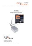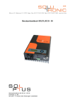
1
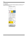
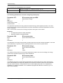
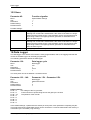
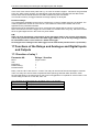
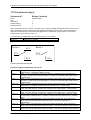
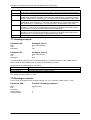
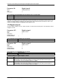
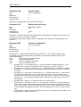
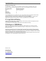
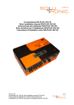
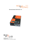
r
SOLPLUS 25 – 55 User Manual
SOLPLUS 25 – 55 User Manual
Firmware: 2.64
MV/ 2012-11 Version: B8, Subject to change without prior notice
SP25-55_User Manual_B8_EN_2012-11-06
2/32
Contents
1
Notes About The User Manual ....................................................................................................... 4
Scope.......................................................................................................................................... 4
More information......................................................................................................................... 4
Abbreviations .............................................................................................................................. 4
Symbols used in this document.................................................................................................. 5
2
Safety .............................................................................................................................................. 6
2.1 Safety in general......................................................................................................................... 6
2.2 Intended use ............................................................................................................................... 6
2.3 Safety instructions ...................................................................................................................... 6
2.4 Non-observance of this User Manual ......................................................................................... 7
2.5 Nameplate .................................................................................................................................. 8
3
Introduction ................................................................................................................................... 10
4
General communication features.................................................................................................. 10
5
Operating states............................................................................................................................ 13
6
Display navigation SOLPLUS 25 - 55........................................................................................... 14
7
Communication with the Inverter Via the RS232 Port .................................................................. 15
8
Communication With the Inverter Via the Ethernet Port and Webbrowser .................................. 15
9
Communication with Several Inverters by means of Master-Slave Data Communication ........... 15
10 SOLPLUS+ Communication Software .......................................................................................... 15
11 Files of the inverter ....................................................................................................................... 16
12 Communication with SolarLog™ .................................................................................................. 17
13 Sensor Connections...................................................................................................................... 17
14 Yield Monitoring ............................................................................................................................ 18
14.1
Integrated energy meter....................................................................................................... 18
14.2
Annual energy logger ........................................................................................................... 18
14.3
Connecting an external energy meter .................................................................................. 18
14.4
Operating hours meter ......................................................................................................... 20
14.5
Integrated yield monitoring................................................................................................... 20
15 Integrated Installation Monitoring.................................................................................................. 21
15.1
Possible causes of an alarm ................................................................................................ 21
15.2
Horn...................................................................................................................................... 23
16 Data Logger .................................................................................................................................. 23
17 Functions of the Relays and Analogue and Digital Inputs and Outputs ....................................... 24
17.1
Function of relay 1................................................................................................................ 24
17.2
Function of relay 2................................................................................................................ 25
17.3
Analogue inputs ................................................................................................................... 26
17.4
Analogue outputs ................................................................................................................. 26
17.5
Digital inputs......................................................................................................................... 27
17.6
Digital outputs....................................................................................................................... 28
18 Password Protection ..................................................................................................................... 29
18.1
Customised protection of the inverter settings..................................................................... 29
19 Resetting to Default Settings ........................................................................................................ 29
20 Other Parameters ......................................................................................................................... 30
21 Large External Display.................................................................................................................. 32
22 Analogue or GSM Modem ............................................................................................................ 32
1.1
1.2
1.3
1.4
SP25-55_User Manual_B8_EN_2012-11-06
3/32
Notes About The User Manual
1 Notes About The User Manual
Dear Customer,
Thank you for buying a SOLPLUS solar inverter designed and manufactured by Solutronic.
This manual describes how to user your SOLPLUS inverter. Please keep it somewhere where you
have ready access to it whenever you need to.
Please comply at all times with the safety precautions we refer to in this manual.
In order to keep the description short, the section on communication deals mainly with the details of
display communication. For all other means of communication, reference is made to the relevant
manuals.
You can carry out all parameter settings described here using any of the different means of
communication available.
1.1 Scope
This User Manual applies to the following Solutronic inverters:
SOLPLUS 25, SOLPLUS 35, SOLPLUS 50, SOLPLUS 55.
1.2 More information
The following documents and software are provided on the accompanying CD and in the download
area of www.solutronic.de and can be used as a reference guide on how to operate your new inverter:
The CD contains the following documents and software:
•
•
•
•
•
•
•
SOLPLUS 25 – 55 Fitters' Manual
DimenSOL+ dimensioning tool (program for designing PV installations)
SOLPLUS+ communication software (for the PC) and user manual
Instructions for GSM/analogue modem (remote monitoring)
Instructions for sensor installation (installation of sensor connections)
Instructions for master-slave data network/yield monitoring
Instructions for Ethernet browser
The SOLPLUS inverters have been developed, manufactured and tested with great care and are
incorporate the very latest technology. Our manufacturing procedures are in accordance with the
stipulations of ISO 9001.
If you encounter any problems or have any questions, please do not hesitate to get in touch with us.
Solutronic AG
Küferstrasse 18
D-73257 Köngen
[email protected]
www.solutronic.de
1.3 Abbreviations
The following abbreviations are used in this manual:
SP 25
SP 35
SP 50
SP 55
=
=
=
=
SOLPLUS 25 – 55
SOLPLUS 35 – 55
SOLPLUS 50 – 55
SOLPLUS 55 – 55
SP25-55_User Manual_B8_EN_2012-11-06
4/32
Notes About The User Manual
SOLPLUS+
=
Read-out and monitoring software for use with all Solutronic inverters
DC
=
AC
=
PV
Generator
=
=
Direct current (direct voltage): electrical value on the input side of the
inverter
Alternating current (alternating voltage): electrical value on the output
side of the inverter
Photovoltaic
Solar generator: interconnection of several solar modules to form a string
or a number of parallel strings
Password level -1
Password level 1
Password level 2
Passwort Level 3
Passwort Level 4
measured value, cannot be changed
client
installer
Safety
Master
1.4 Symbols used in this document
Please read and observe the following safety instructions in this manual.
The danger classes describe the risks of non-observance of the safety instructions.
(The safety instructions describe the following danger classes per ANSI.)
Attention!
"Attention!" denotes a warning that, if not observed, can result in property
damage!
Caution!
"Caution!" denotes a warning that, if not observed, can result in personal
injury!
Warning!
"Warning!" denotes a warning that, if not observed, can result in death or
serious injury!
Danger!
"Danger!" denotes a warning that, if not observed, will result in death or
serious injury!
Note
Useful information and tips to help you operate the SOLPLUS inverter to
best effect.
SP25-55_User Manual_B8_EN_2012-11-06
5/32
Safety
2 Safety
2.1 Safety in general
Please read the following safety information and instructions before you put the SOLPLUS inverter
into operation for the first time, in order to avoid personal injuries and/or property damage. These
instructions must be complied with at all times.
Do to attempt to install or put the SOLPLUS inverter into service until you have read through all the
documentation supplied thoroughly. Read through these safety instructions and all other user
instructions and tips before you begin work with this device.
If you sell on, hire out or pass on this device to someone else in some other way, make sure that you
give the new user these safety instructions, too.
2.2 Intended use
This device must be used only for the purpose described in this User Manual. The inverter is designed
for use in grid-connected photovoltaic installations. All safety regulations must be complied with. All
installation work must be carried out precisely as described in this manual. No modification of any kind
to or in this device or to its external wiring is permitted. Any such modification could lead to serious
safety problems and danger to life and limb.
2.3 Safety instructions
Warning!
Improper use of these devices, non-observance of the warnings given in
this manual and improper tampering with the safety functions can lead to
property damage, personal injury, electric shock and, in extreme cases,
death.
Caution!
The surface of the inverter housing can become hot when the inverter is in
operation. Very hot! Do not touch!
Danger!
High voltage due to incorrect connection! Risk of fatal or bodily injury from
electric shock.
SP25-55_User Manual_B8_EN_2012-11-06
6/32
Safety
2.4 Non-observance of this User Manual
Solutronic AG shall accept no liability for damages resulting from non-observance of the warnings
given in this User Manual.
Read the operating, maintenance and safety instructions before you put the device into operation for
the first time. If you are not able to understand the language used in this documentation sufficiently,
please contact and inform the supplier of the situation.
Trouble-free and safe operation of this inverter presumes proper, professional and workmanlike
transportation, storage, mounting and installation as well as careful operation and thorough
maintenance.
Notice
Solutronic AG is not liable for the consequences arising from faulty
installation of the inverter!
Among these consequences are:
• Damage to the display and keyboard foil, deterioration of readability
• Fading of the print on the housing, the look of the housing
deteriorates
Therefore, chose the place of installation for the inverter so that the device
is not directly or indirectly exposed to UV radiation:
• The device must not be exposed to direct sunlight
• The device must be protected from reflections by glass facades or
PV modules
SP25-55_User Manual_B8_EN_2012-11-06
7/32
Safety
2.5 Nameplate
You can identify the model of your inverter by looking at the nameplate. The nameplate, which carries
the precise type designation of the inverter, is located on the right-hand side of the housing. The
example is valid for SOLPLUS 25 – 55.
Nameplate of a SP 35
S/N 0938-0001
SP 35, IP 21
MC4
MAC: 0021EC050001
SP25-55_User Manual_B8_EN_2012-11-06
8/32
Safety
2.5.1 Explanation of the symbols used on the nameplate
The nameplate provides the following information:
Attention! Hot surfaces!
Attention and danger!
Observe the operating instructions!!
Waste Electrical and Electronic Equipment (WEEE)
Solar inverters must not be disposed of with household waste. Please
return the device to Solutronic after it has reached the end of its useful
life.
Attention! The inverter may still carry voltage even after it has been
disconnected from the PV installation and grid. Please be sure to wait
until the capacitors have fully discharged (discharge period).
S/N 0938-0001
SP 35, IP 21
MC4
MAC: 0021EC050001
•
•
•
•
Production date and serial number
Inverter model and degree of protection
Connectors at DC end
MAC address of integrated Ethernet port
SP25-55_User Manual_B8_EN_2012-11-06
9/32
Introduction
3 Introduction
Each SOLPLUS inverter features a number of interfaces and communication ports via which the data
of the inverter can be read out. A total of approximately 300 inverter parameters can be read out.
The data provided by the inverter are divided into the following categories:
1
Yield and display values: These values represent the instantaneous values of the inverter.
They are actual values and display values that cannot be altered.
2
Setting values: These are values that can be set and altered individually. Depending on the
importance and meaning of the parameters, these values can be set by the final customer, the
fitter or the utility company. For security purposes, different password levels are incorporated.
4 General communication features
3
9
11
10
8
6
4
5
2
1
7
SOLPLUS 25 - 55
1
RS232 X1
7
2
RS485 X2
8
3
4
5
6
Slot for option cards
9
Ethernet X7
DC switch
DC connections
External connector X4
10
Additional PE connection
External terminal strip X5
11
DC connections
Auxiliary power supply X6
Note
An external plug-in AC adapter can be used to provide an auxiliary
power supply.
12 V DC
300 mA, with built-in modem 1 A
Connector, 5.5 x 2.1 pin + (positive), sheath – (negative)
SP25-55_User Manual_B8_EN_2012-11-06
10/32
General communication features
Parameter 265:
COM1 log type
Menu:
Unit:
Resolution:
Default setting:
Password level:
Communication/Basic settings
--1
0
1
Parameter 265 defines which protocol is used for communication via the standard port, COM1, of the
inverter. COM1 is both the 9-pin SubD female connector X1 for RS232 and also the 3-pin terminal
strip X2 for RS485.
The signals for X1 and X2 are connected together in circuit in the inverter. This means that it is not
possible to use different protocols via the standard RS232 and the standard RS485 at the same time.
General notes on parameter 265:
Value
Meaning
0
ASCII protocol (for using the inverter with HyperTerminal)
1
Solutronic protocol (for using the inverter with SOLPLUS+). N.B.: Leave parameter 265
set to the value 0; 0 = ASCII protocol is automatically switched internally to 1 =
Solutronic protocol
2
Debug function. Do not use.
3
Modem with ASCII protocol
4
Modem with Solutronic protocol. N.B.: When operating via modem, leave parameter 265
set to the value 3; 3 = Modem with ASCII protocol is automatically switched internally to
4 = Modem with Solutronic protocol
5
Not active
6
Not active
7
GSM modem with ASCII protocol
8
Not active
9
SolarLog protocol for SolarLog™ data logger
Note
SolarLog™ and Solutronic's master-slave data communication function
can not be used at the same time.
SP25-55_User Manual_B8_EN_2012-11-06
11/32
General communication features
Parameter 266:
COM2 log type
Menu:
Unit:
Resolution:
Default setting:
Password level:
Communication/Basic settings
--1
0
1
Parameter 266 defines which protocol is used for communication via the second COM2 port of the
device. COM2 is accessible in the form of the RS232 port at X4 (25-pin SubD female connector). The
option card (modem, RS485) is also connected via COM2. The signals for X4 or the option cards are
connected together in circuit in the inverter. This means that it is not possible to use different protocols
via the second RS232 and the option cards.
The following settings are possible:
Value
Meaning
0
ASCII protocol (for using the inverter with HyperTerminal)
1
Solutronic protocol (for using the inverter with SOLPLUS+). N.B.: Leave parameter 266
set to the value 0; 0 = ASCII protocol is automatically switched internally to 1 =
Solutronic protocol
2
Debug function. Do not use.
3
Modem with ASCII protocol
4
Modem with Solutronic protocol. N.B.: When operating via modem, leave parameter 266
set to the value 3; 3 = Modem with ASCII protocol is automatically switched internally to
4 = Modem with Solutronic protocol
5
Large RiCo display
6
Large Schneider display
7
GSM modem with ASCII protocol
8
Not active
9
SolarLog protocol for SolarLog™ data logger
Note
SolarLog™ and Solutronic's master-slave data communication function
can not be used at the same time.
N.B.: If you want to operate the inverter directly and locally using a PC, please use the 0 setting
(default setting).
In this case, it is unimportant whether you use RS232 or RS485 to establish a link with the inverter or
the inverter's data network.
Automatic switch-over of the type of protocol from 0 to 1 (i.e. from operation with HyperTerminal to
operation with SOLPLUS+) cannot be reversed. To do so, the inverter would have to be reset, i.e.
switched off and on again. The same applies to automatic "switch-over" of the type of protocol from 3
to 4 (i.e. from modem operation with HyperTerminal to modem operation with SOLPLUS+).
If the protocol setting is 3, 4, 5 or 6, this port cannot be used directly with HyperTerminal or
SOLPLUS+. To do so, the corresponding parameter has to be reset either by means of the display or
via the other port.
SP25-55_User Manual_B8_EN_2012-11-06
12/32
Operating states
5 Operating states
The operating states of the SOLPLUS 25 - 55 inverters are indicated by means of a light-emitting
diode (LED) and on the display.
The LED has two colours and indicates the instantaneous operating state of the inverter. The actual
operating state is indicated on the display.
For the operating state to be identified, the DC side of the inverter must be connected to the PV
modules and a minimum voltage of approx. 280 V must be input into the inverter.
Example SOLPLUS 25 – 55 display
LED
P
1
Production date
Meaning the operating states
LED
Explanation
Constantly lit
green
Grid-feed mode
Flashing green
Initialisation or standby, e.g. because the
voltage of the solar generator is too low
SOLPLUS 50
PAC=0W
Initialisation
Menu ►
Flashing red/green
Fault has occurred
SOLPLUS 50
PAC=0W
Initialisation
Menu ►
or
Restart in progress
Constantly lit red
Fault in at least one phase of the inverter
Display content
SOLPLUS 50
PAC=2510 W
Grid-feed mode
Menu ►
SOLPLUS 50
PAC=0 W
Grid failure
Menu ►
What to do in the case of a fault
If the LED on the inverter lights up red or red/green, read up the fault description in the
Installation Instructions manual or note down the warning/alarm/fault message indicated on the
display and contact your fitter.
It is best if you read out all the data supplied by the SOLPLUS inverter: the last fault displayed,
fault memory, data logger and list of all parameters.
SP25-55_User Manual_B8_EN_2012-11-06
13/32
Display navigation SOLPLUS 25 - 55
6 Display navigation SOLPLUS 25 - 55
Base window: by pressing a button the display turns on and the main screen appears.
The basic menu is accessed by pressing the down arrow key on the display. In the basic menu, the yield values can be read. By pressing the arrow key left, you return to the base
window.
The main menu is accessed by pressing the arrow key to the right. Before entering the main menu, the password is requested. The sequence (up/right/down/up/right/down), confirmed with “OK”, enters the main menu. Inside the main menu you could modify in several submenus the desired parameters. By pressing the
left key, you return to the base window.
The actual value menu could be accessed by pressing the arrow key left. It is separated into four menu groups. Inside, you could access several parameters. By pushing the
arrow key left again, you reach the following menus. At the end you get back to the base window. (more information on the display menu can be found on the CD and the download
section at www.solutronic.de).
Basic configuration
Password request
Actual value menu
INPUT
DC voltage
DC current
power DC
231 V
7,6 A
1794W
Actual value menu
Actual value menu
SOLPLUS 35
PAC : 3416 W
grid-feed mode
Menu
Basic menu
INPUT
INVERTER
YIELD MONITOR
Main menu
Basic menu
energy today
OUTPUT
Enter password
Press key combination and
Confirm with OK
Main menu
0,0kWh
energy total
0,0kWh
amount euro today
0,0€
amount euro total
0,0€
firmware version
1,29
SPP Address
2
IP: 192.168.0.99
-
11:56:17 (time)
-
15.12.2011 (data)
-
Device Configuration
Safety
Power Reduction
Reactive Power
Communication
slave data
Datalogger
installation data
Maintenance
annual energy logger
Yield control
Options
SP25-55_User Manual_B8_EN_2012-11-06
14/32
Communication with the Inverter Via the RS232 Port
7 Communication with the Inverter Via the RS232 Port
All that is required to connect the inverter to a PC is a serial connection cable. Only pins 2, 3 and 5 are
relevant in respect of the wiring in the cable. The cable should be no more than 15 metres long.
The PC or laptop to be connected must have an RS232 port. If the computer is equipped with just a
USB port, a USB–RS232 port adapter cable must be used.
Data are read out by means of the SOLPLUS+ or HyperTerminal software.
8 Communication With the Inverter Via the Ethernet Port
and Webbrowser
With the help of a PC, you can use the Ethernet link to control the inverter via a web browser or
Solutronic's communication software SOLPLUS+. Provided that your converter is connected to a
network and has been configured correctly, you can call up and read out data from your inverter via
any PC connected to the network.
N.B.: Internet Explorer has difficulties displaying carriage returns and line feeds in text files. We
therefore recommend you use Mozilla Firefox as the web browser.
If you are interested in setting up this form of communication, please load the instructions for the
Ethernet browser from the CD supplied or download them from www.solutronic.de.
9 Communication with Several Inverters by means of
Master-Slave Data Communication
The master-slave data communication function is used to network up to 32 inverters in an installation.
For this purpose, the inverters must be connected to each other via the standard RS485 port. One of
the inverters in the installation is defined as the "data master". The display of this inverter then shows
the most important data (the data of the basic menu). The "data master" also records the current
power level and the yields of the "data slaves" and adds them together.
If you are interested in setting up this form of communication, please load the instructions for masterslave data communication from the CD supplied or download them from www.solutronic.de.
10 SOLPLUS+ Communication Software
SOLPLUS+ is a Windows program for evaluating inverter data and incorporates the following basic
functions:
•
Configuration of the inverter
•
Connection to the inverter via RS232, Ethernet and modem
•
Easy configuration of an installation: you can store different configurations, i.e. different
installations. For example, you can monitor an installation with 2 inverters on your roof via
RS232 or RS485. You can then load a new configuration to call up and monitor an installation
that consists of 10 inverters via modem.
•
In the same way as with the display, you can use SOLPLUS+ to configure your inverter how
you want to. You can also use the PC to enter a password and then change settings that are
not relevant to safety.
•
Modification and implementation of the various "files" that the inverter supplies: list of all
parameters, fault memory, annual energy logger etc.
SOLPLUS+ reads out the data logger and transfers the data to the PC. The values to be read out and
displayed must be selected individually by the user. All parameters can be read out. Simple operator
control and a Help function make it possible to monitor how your PV installation is functioning and its
yield.
SP25-55_User Manual_B8_EN_2012-11-06
15/32
Files of the inverter
If you are interested in using SOLPLUS+ to monitor your inverter, please load the program and the
installation and user manuals of SOLPLUS+ from the CD supplied or download them from
www.solutronic.de.
11 Files of the inverter
The inverter generates various "files", which can be read out via one of its communication ports and
communication modes.
File number
0
1
Name
No file
Fault memory
2
List of all parameters
5
List of actual values
6
Data logger
7
Annual energy logger
8
Annual sensor logger
9
Annual sensor/energy
logger
10 (A)
13 (D)
Configuration of data
logger
Installation monitoring
14 (E)
Alarms
Description
The fault memory – a list of the last 100 faults, with
date, time and fault number. These are stored in the
sequence in which they occurred (with date and
timestamp).
A table showing all the parameters of the inverter, with
parameter number, parameter name, parameter value
and unit
A table showing all parameters and the actual values,
i.e. values which can be changed
The data logger: entries with a time stamp and values
of the parameters
A table in the form of a ring memory (endless loop
memory) about the preceding year with the achieved
yield of each respective day in kWh. Resolution: 0.1
kWh
A table in the form of a ring memory (endless loop
memory) about the preceding year with the achieved
"theoretical yield" of the insolation sensor (if connected)
on each respective day in kWh. Resolution: 0.1 kWh
A table in the form of a ring memory (endless loop
memory) relating to the preceding year, with the
achieved yields of the inverter and the insolation sensor
(if connected) on each respective day in kWh.
Resolution: 0.1 kWh
A description of the configuration (contents) of the data
logger with the estimated storage times
A list with the yield values of the master, insolation
sensor and all slaves as well as the yield values of the
master, sensor and all slaves relative to the connected
nominal DC output. This list is in the form of a ring
memory (endless loop memory) and has been created
over the course of the preceding year. It cannot be read
until the integrated yield monitoring function has been
started and successfully ended (see chapter entitled
"Yield monitoring")
A list of the alarms which occurred on this day. These
are stored in this file in the sequence in which they
occurred. Additional information as well as the time are
also stored here
The above files can be created and read out using SOLPLUS+ or the web browser.
SP25-55_User Manual_B8_EN_2012-11-06
16/32
Communication with SolarLog™
12 Communication with SolarLog™
The data logger known as SolarLog™ from Solare Datensysteme GmbH can be used to network up to
32 inverters in an installation.
Please note that SolarLog™ and Solutronic's master-slave data communication function cannot be
used at the same time.
For communication with SolarLog™ the inverters and SolarLog™ must be connected to each other via
the standard RS485 port. Note the pin assignments of the RS485 connectors, which differ as follows:
RS485 A (+)
RS485 B (-)
Masse
SP100 / 120
M12 farbcodiert
weiß
schwarz
blau
SP100 / 120
M12
2
4
3
-frei-
SP25 - 55
3polig
1 (links)
2 (mitte)
3 (rechts)
SP25 -55
Patch
3 (gn/ws)
6 (gn)
1+2 (or or-ws)
SolarLog
1
4
3
2
Weitere Information zum Betrieb und zur Einstellung von SolarLog finden Sie im
„Installationshandbuch Solarlog“ auf www.solutronic.de.
13 Sensor Connections
A large number of different sensors can be connected to the inverter. The following sensor types are
currently supported:
Manufacturer
Type/Model
Remark
Mencke & Tegtmeyer
Si-01TC
Insolation sensor with internal
lithium battery
Usage conditional due to limited
service life of the battery
Mencke & Tegtmeyer
Si-01TCext
Insolation sensor
Mencke & Tegtmeyer
Si-01TC-T
Tritec
Spektron 300
Insolation sensor with
temperature sensor, see
description of parameter 209
Insolation sensor
This list is constantly being added to. Please contact us if you would like information on a type/model
of sensor that is not in the list above.
If you interested in connecting sensors, please load the corresponding instructions on connecting
sensors from the CD supplied or download them from www.solutronic.de. You will also find additional
information there.
SP25-55_User Manual_B8_EN_2012-11-06
17/32
Yield Monitoring
14 Yield Monitoring
14.1 Integrated energy meter
The inverter is equipped with an integrated energy meter that calculates and adds up the energy fed
into the mains power supply (accuracy: approx. 1.5%).
N.B.: The energy meter of the inverter deliberately indicates a value approx 1.5% lower than that
actually fed into the grid. The purpose of this is to ensure the inverter does not indicate to you, the
owner, a value that is higher than that recorded by the actual "calibrated" export meter of your power
supplier.
Parameter 8:
Energy today
Menu:
Unit:
Resolution:
Default setting:
Password level:
Actual values/Yield monitor
kWh
0,001 kWh
0
1
This displays the amount of energy fed into the grid so far today.
N.B.: The value is not saved and the amount of energy fed in during the whole day is displayed shortly
before it becomes dark.
Parameter 12:
Energy total
Menu:
Unit:
Resolution:
Actual values
kWh
1 kWh
This parameter is used to display the total amount of energy the inverter has fed into the power supply
system since its installation.
Parameter 29:
Compensation Euro per kWh
Menu:
Unit:
Resolution:
Default setting:
Password level:
Yield control
€/kWh
0,0001 €/kWh
0.287€/kWh
1
This parameter displays the currently applicable compensation per kW/h of energy supplied to the
grid.
14.2 Annual energy logger
The inverter records the daily yield for every day of the year. The inverter is equipped with a memory
that stores the yield for 365 days. This memory is cyclical, i.e. after a year, it overwrites the old values
stored.
The annual energy logger can be read out via any of the available communication ports.
You call up the annual energy logger in the display from the basic menu.
14.3 Connecting an external energy meter
To enable additional monitoring of yield, it is also possible to connect an external energy meter
(electricity meter) with S0 output (prerequisite) directly to the inverter.
This external energy meter may be the actual export meter used by the utility company to record the
amount of electricity fed into the grid. Due to the fact that the internal energy meter of the inverter is
deliberately inaccurate, the option of connecting an external energy meter enables the exact value the
PV installation actually yields to be recorded and displayed.
The external energy meter output pulses via the S0 output, which the inverter detects and records.
Connecting the external energy meter to connector X4 of the inverter:
SP25-55_User Manual_B8_EN_2012-11-06
18/32
Yield Monitoring
The connector pin assignments are as follows:
X4, pin 13
Positive connection of the S0: output of the energy meter.
Maximum voltage: 5 V; maximum current: 16 mA
X4, pin 23
Ground = negative connection of the S0: output of the energy meter
The following parameters are used for configuring and displays:
Parameter 127:
SO-counter pulse per kWh
Menu:
Unit:
Resolution:
Default setting: 2000
Password level:
Options/basic settings
--1
1
This parameter specifies how many pulses the external energy meter supplies per kWh. This value
can be found on the external meter itself and it must be entered here under this parameter to ensure
correct calculation.
N.B.: In some cases, the amount of energy per pulse is also given on the meters.
Examples:
• 0.5 Wh/pulse equates to 2000 pulses/kWh
• Wh/pulse equates to 500 pulses/kWh
Parameter 128:
SO-counter pulse
Menu:
Unit:
Resolution:
Actual values/Yield monitor
--1
This parameter counts the actual number of pulses input and is used for internal calculation. The value
of this parameter is regularly saved to guard against loss in the event of a power failure.
Parameter 151:
SO-counter energy
Menu:
Unit:
Resolution:
Actual values/Yield monitor
kWh
1 kWh
If an external energy meter is connected and parameter number 127 is set accordingly, the energy
measured by the external (S0) energy meter is displayed.
Parameter 222:
SO-counter power
Menu:
Unit:
Resolution:
Actual values/Yield monitor
W
1
This displays the power currently being measured by the external (S0) energy meter. Note that the
power value displayed is always time-delayed and rounded off because it has to be back-calculated
from the number of pulses. This parameter can be used to display the power of a "neighbouring
installation" or "external installation" in an installation equipped with Solutronic inverters (e.g. for a
large external display).
SP25-55_User Manual_B8_EN_2012-11-06
19/32
Yield Monitoring
Parameter 224:
SO-counter energy day
Menu:
Unit:
Resolution:
Actual values/Yield monitor
kWh
0,001kWh
This displays the "day yield", i.e. the yield on a particular 'today', measured by the external (S0) power
meter. This parameter can be used to display the day yield of a "neighbouring installation" or "external
installation" in an installation equipped with Solutronic inverters (e.g. for a large external display).
Parameter 225:
SO-counter pulse today
Menu:
Unit:
Resolution:
Actual values/Yield monitor
--1
The number of S0 pulses measured 'today' is accurately recorded here.
14.4 Operating hours meter
The inverter uses the following parameters to display the number of operating hours:
Parameter 123:
Operating hours today
Menu:
Unit:
Resolution:
Actual values/Yield monitor
h (Stunde)
0,1 h
Parameter 123 displays the length of time the inverter has already been switched on today.
The meter starts running as soon as the solar generator delivers an adequate voltage.
Parameter 124:
Operating hours total
Menu:
Unit:
Resolution:
Default setting:
Password level:
Actual values/Yield monitor
h (Stunde)
0,1 h
--4
Parameter 124 records and stores the total length of time the inverter has been switched on since it
was first started up.
14.5 Integrated yield monitoring
Each inverter is equipped with and capable of activating an integrated yield monitoring function. This
function is based on the comparison of yield data either from one inverter with an insolation sensor
connected or from an installation comprising at least 2 inverters that are networked by means of their
RS485 ports.
Details of how the yield monitoring function works can be found in the instructions for the master-slave
data network and in those for the sensor. Both manuals can be found on the CD supplied or can be
downloaded from www.solutronic.de. Your dealer can supply you with the activation code.
SP25-55_User Manual_B8_EN_2012-11-06
20/32
Integrated Installation Monitoring
15 Integrated Installation Monitoring
Each inverter is equipped with an integrated installation monitoring function. This means it regularly
performs a number of checks and warns the installation's owner in the event of a critical condition
arising or variations in yield occurring.
If the inverter detects a critical condition or yield variation, it continues to function – insofar as this is
possible – but outputs an alarm both visually and acoustically. An alarm is given by the following
means:
•
Acoustic alarm: the alarm horn integrated in the inverter emits an intermittent alarm tone. It
sounds for half a second every second. The alarm horn can be switched off by pressing any
button.
•
The LCD display switches on. The word "Alarm" and the cause of the alarm are displayed
alternately in the third line of the basic (start) screen.
•
The LED on the cover of the inverter flashes red and green alternately.
•
The number of the alarm is also displayed in parameter 155 (in the Installation Monitoring
menu).
If the inverter is being operated via a communication port, a file that is continuously written to and has
the name "File 14 Alarms" can be read out. This file is empty in the morning and, insofar as (several)
alarms occur during the course of the day, has the various alarm texts, additional explanations and the
times at which the alarms occurred written to it.
15.1 Possible causes of an alarm
The following causes of an alarm are possible:
Alarm
Description
number
0
No alarm
1
UAC not okay. This text is displayed if the
mains voltage is lower than the minimum alarm
threshold or higher than the maximum alarm
threshold for the mains voltage for longer than
2 minutes.
2
UDC too high. This text is displayed if the DC
voltage is higher than the maximum DC voltage
alarm threshold for longer than 1 minute.
Inverter too hot. This text is displayed if the
inverter temperature is higher than 65°C for
longer than 2 minutes.
Yield sensor. This text is displayed if the yield
monitoring function (see section on yield
monitoring) has detected during the last 5 days
a variation between the yield of the inverter and
the "theoretical yield" of the sensor that
exceeds the value of P280.
Yield slaves. This text is displayed if the yield
monitoring function (see section on yield
monitoring) has detected during the last 5 days
a variation between the yield of the inverter and
the yield of the slave that exceeds the value of
P280.
Communication. This text is displayed if data
communication between the master and the
slaves is disrupted.
Mains frequency. This text is displayed if the
variation from the rated mains frequency of
3
4
5
6
7
SP25-55_User Manual_B8_EN_2012-11-06
Dependent
upon
Attribute
represents:
-
Bit of
P279
-
P50: Max.
mains voltage
alarm threshold;
P52: Min. mains
voltage alarm
threshold
P58: Max. DC
voltage alarm
threshold
Value of the
mains
voltage
0
Value of the
DC voltage
1
Value of the
inverter
temperature
-
2
P280: Yield
variation
P280: Yield
variation
P76: Max.
alarm threshold
3
Number of
the slave
4
Number of
the slave
5
Value of the
mains
6
21/32
Integrated Installation Monitoring
50 Hz is higher than the alarm threshold for this
variation for longer than 5 minutes.
8
9
Frequent faults. This text is displayed if, during
the past 2 hours, the same fault has occurred
more than 3 times in succession or if more than
6 different faults have occurred.
External. This text is displayed if an external
alarm has been tripped.
Parameter 279:
Configuration warning
Menu:
Unit:
Resolution:
Default setting:
Password level:
Maintenance
--1
383
1
for variation
from rated
frequency of 50
Hz
frequency
Number of
the fault (fault
code)
7
-
8
Each of the 9 alarms described above can be activated or deactivated separately.
Parameter 279 is bit-programmed, i.e. each of its bits activates or deactivates one of the 9 alarms.
8
7
6
5
External Frequent
Grid
Commuwarning
faults
frequency nication
1
0
1
1
1
0
1
0
1
1
1
0
4
Yield
slaves
1
1
1
3
2
1
Yield Temperat UDC too
sensor
ure
high
1
1
1
1
1
1
1
1
1
0
= Bit
UAC not = decimal
OK
1
= 383
1
= 351
1
= 479
Example:
The installation comprises several inverters that are networked by means of their RS485 ports.
However, since the PV generators of the installation have very different orientations (i.e. point in
different directions), integrated yield monitoring is to be performed but no alarm is to be given in the
event of a variation in yield. All other alarms, however, are to remain active. This means that bits 0, 1,
2, 3, 5, 6, 7 and 8 are to remain set, but bit 4 must be deleted. This results in a binary value for P279
of 111101111, which equates to a decimal value of 495. P279 must therefore be set to 495.
Parameter 155:
Status warning
Menu:
Unit:
Resolution:
Maintenance
--1
Parameter 155 displays the alarm (warning) currently active. You can find details in the table above.
Please note that only the first alarm given on the particular day is displayed. If further alarms occur
during the course of the day, they are not recorded as subsequent or secondary alarms.
SP25-55_User Manual_B8_EN_2012-11-06
22/32
Data Logger
15.2 Horn
Parameter 45:
Function signaller
Menu:
Unit:
Resolution:
Default setting:
Password level:
Options/Basic settings
--1
0
1
Possible settings:
Value = 0
Value = 1
Value = 2
Value = 3
The signal generator generates an intermittent tone when an alarm is given.
The signal generator generates an intermittent tone as long as the inverter is
suffering from a fault and is deactivated. If the cause of the fault is no longer
present and the inverter begins a new activation check, the intermittent tone
stops being emitted. The signal generator generates an intermittent tone
when an alarm is given.
The signal generator generates a continuous tone as long as the inverter is
suffering from a fault and is deactivated. If the cause of the fault is no longer
present and the inverter begins a new activation check, the continuous tone
stops being emitted. The signal generator generates an intermittent tone
when an alarm is given.
The signal generator is always Off.
16 Data Logger
The data logger of the SOLPLUS inverters is freely programmable, that is, the logging intervals and
content of the data logger can be freely programmed.
The following parameters define the data logger:
Parameter 130:
Data logger cycle
Menu:
Unit:
Resolution:
Default setting:
Password level:
Data logger
min
1
5 min
1
The clock pulse can be set between 1 and 60 minutes.
Parameter 133 – 140:
Parameter 1 DL - Parameter 8 DL
Menu:
Unit:
Resolution:
Default setting:
Password level:
Data logger
Parameternummer
1
2
1
Default settings:
P133 = 2
DC voltage of the PV generator
P134 = 5
Current amount of power being fed into the grid by the inverter
P135 = 16
Temperature of the inverter
P136 = 0
P137 = 0
P138 = 0
P139 = 0
P140 = 0
In the default settings, 3 parameters are stored per clock pulse, each parameter comprising 2 bytes.
This means that around 5,000 data entries can be recorded in a 5-minute raster before the memory is
overwritten by the new data ("ring memory").
SP25-55_User Manual_B8_EN_2012-11-06
23/32
Functions of the Relays and Analogue and Digital Inputs and Outputs
In the case of a 5-minute clock pulse and e.g. 14 hours of sunshine, approx. 168 entries are generated
every day. After roughly 29 days, the data logger is full and begins overwriting the first data entries
stored: these entries should therefore be read out before they are overwritten.
The inverter's memory for logger data has a storage capacity of 30 Kbytes.
Possible settings:
The 8 parameters available can be used to configure the content of a data logger line as desired. The
minimum parameter number in each case is 0, the maximum number 254. Please refer to the
appendix for the parameter numbers.
Note that the list of parameters from 133 to 140 begins with values that are not zero. The first entry
that is 0 means the end of the logger list. The inverter now creates "files" every day, which the inverter
saves to guard against loss in the event of a power failure.
N.B.:
After you have changed the configuration of the data logger (that is, the content of parameters
133 to 140), you have to delete the entire data logger memory. You do this by setting parameter
66 "Set default values" to the value 70 = Delete data logger.
All changes to the settings of the data logger can be made under password level 1 (Customer).
17 Functions of the Relays and Analogue and Digital Inputs
and Outputs
17.1 Function of relay 1
Parameter 46:
Relays 1 function
Menu:
Unit:
Resolution:
Default setting:
Password level:
Output control
--1
1
1
Relay 1 has one N.O. and one N.C. contact. The relay can be used to forward messages to external
units. This relay can also be used to implement alarm (warning) and fault alarm functions. Other
functions will follow in the future and you may send us suggestions or requests for such functions. The
contact rating is 230V AC or 30V DC, max. 5 A.
The connector pin assignments are as follows: (Pin 1 is on the left)
X5, pin 1
Relay 1, two-way contact COM
X5, pin 2
Relay 1, N.O. contact
X5, pin 3
Relay 1, N.C. contact
SP25-55_User Manual_B8_EN_2012-11-06
24/32
Functions of the Relays and Analogue and Digital Inputs and Outputs
17.2 Function of relay 2
Parameter 47:
Relays 2 function
Menu:
Unit:
Resolution:
Default setting:
Password level:
Output control
--1
0
1
Relay 2 has just one N.O. contact. The relay can be used to forward messages to external units. This
relay can also be used to implement alarm (warning) and fault alarm functions. Other functions will
follow in the future and you may send us suggestions or requests for such functions. The contact
rating is 230V AC or 30V DC, max. 5 A.
The connector pin assignments are as follows: (Pin 1 is on the left)
X5, pin 4
Relay 2, two-way contact COM
X5, pin 5
Relay 2, N.O. contact
Relais 1
X5.3
X5.1
Relais 2
X5.4
X5.2
X5.5
Contacts illustrated deenergised
Possible settings for parameters 46 and 47:
Value = 0
Value = 1
Value = 2
Value = 3
Value = 4
Value = 5
Value = 6
Value = 7
Value = 8
Value = 9
Relay 1 or 2 always deenergised. The COM and N.O. contacts are always open. The
COM and N.C. contacts are always closed.
Relay 1 or 2 is energised as long as the inverter is suffering from a fault and is not
operating. In this case, the COM and N.O. contacts are closed and the COM and N.C.
contacts open.
Relay 1 or 2 is energised as long as the inverter is not suffering from a fault and is
operating. In this case, the COM and N.O. contacts are closed and the COM and N.C.
contacts open.
Relay 1 or 2 is energised as long as the inverter displays an alarm. In this case, the
COM and N.O. contacts are closed and the COM and N.C. contacts open.
Relay 1 or 2 is energised as long as the inverter is not displaying an alarm. In this
case, the COM and N.O. contacts are closed and the COM and N.C. contacts open.
Relay 1 or 2 is energised as long as the inverter displays an alarm or a fault. In this
case, the COM and N.O. contacts are closed and the COM and N.C. contacts open.
Relay 1 or 2 is energised as long as the inverter is not displaying an alarm or a fault.
In this case, the COM and N.O. contacts are closed and the COM and N.C. contacts
open.
Relay 1 or 2 is energised if the inverter temperature (parameter 16) is higher than
50°C. If the inverter temperature falls below 48°C, the relay in question is
deenergised.
Relay 1 or 2 is energised if the inverter temperature (parameter 16) is higher than
55°C. If the inverter temperature falls below 53°C, the relay in question is deenergised.
Relay 1 or 2 is energised if the inverter temperature (parameter 16) is higher than
60°C. If the inverter temperature falls below 58°C, the relay in question is deenergised.
SP25-55_User Manual_B8_EN_2012-11-06
25/32
Functions of the Relays and Analogue and Digital Inputs and Outputs
Value = 10
Value = 11
Value = 12
Value = 13
Value = 14
Value = 15
Value = 16
Relay 1 or 2 is energised if the inverter temperature (parameter 16) is higher than
65°C. If the inverter temperature falls below 63°C, the relay in question is deenergised.
Relay function is reserved for the de-icing option.
Relay 1 or 2 is energised as long as the inverter is suffering from the fault "3-phase
VDEW fault" and is not operating. In this case, the COM and N.O. contacts are closed
and the COM and N.C. contacts open. The relay function is deactivated in night mode.
Relay 1 or 2 is energised as long as the inverter is not suffering from the fault "3-phase
VDEW fault" and is operating. In this case, the COM and N.O. contacts are closed and
the COM and N.C. contacts open. The relay function is deactivated in night mode.
Relay 1 or 2 is energised as long as the inverter is suffering from a fault and is not
operating. In this case, the COM and N.O. contacts are closed and the COM and N.C.
contacts open. The relay function is deactivated in night mode.
Relay 1 or 2 is energised as long as the inverter is not suffering from a fault and is
operating. In this case, the COM and N.O. contacts are closed and the COM and N.C.
contacts open. The relay function is deactivated in night mode.
Relay 1 or 2 is constantly energised.
17.3 Analogue inputs
Parameter 22:
Analogue input 1
Menu:
Unit:
Resolution:
Actal values/Sensor
V
0,01
Parameter 23:
Analogue input 2
Menu:
Unit:
Resolution:
Actal values/Sensor
V
0,01
The two analogue inputs can be used to feed signals from external sensors or other similar devices
into the inverter and to display them by means of parameters 22 and 23.
The connector pin assignments are as follows:
X4, pin 7
Analogue input 1, 0 to 10 V
X4, pin 8
Analogue input 2, 0 to 10 V
X4, pin 19 or 20
Ground reference for analogue inputs
The maximum input voltage is +/- 30V.
17.4 Analogue outputs
Each inverter is equipped with 2 analogue outputs: 0 to 10 V, maximum output current = 4 mA.
Parameter 298:
Function of analogue output 1
Menu:
Unit:
Resolution:
Default setting:
Password level:
Output control
----0
1
SP25-55_User Manual_B8_EN_2012-11-06
26/32
Functions of the Relays and Analogue and Digital Inputs and Outputs
Parameter 299:
Function of analogue output 2
Menu:
Unit:
Resolution:
Default setting:
Password level:
Output control
----0
1
Possible settings for analogue outputs 1 and 2:
Value = 0
Set output to 0 V
Value = 1
Set output to DC voltage (UDC). 400 V correspond to 4.00 V
Value = 2
Set output to DC current (IDC). 5.00 A correspond to 5.00 V *
Value = 3
Set output to DC current (IDC). 12.00 A correspond to 6.00 V
Value = 4
Set output to AC current (IAC). 5.00 A correspond to 5.00 V *
Value = 5
Set output to AC current (IAC). 12.00 A correspond to 6.00 V *
Value = 6
Set output to AC current (IAC). 22.00 A correspond to 5.50 V
Value = 7
Set output to AC power fed to grid (PAC). 500 W correspond to 5.00 V *
Value = 8
Set output to AC power fed to grid (PAC). 1,200 W correspond to 6.00 V *
Value = 9
Set output to AC power fed to grid (PAC). 3,000 W correspond to 7.50 V *
Value = 10
Set output to AC power fed to grid (PAC). 5,000 W correspond to 5.00 V
Value = 11
Set output to DC power (PDC). 500 W correspond to 5.00 V *
Value = 12
Set output to DC power (PDC). 1,200 W correspond to 6.00 V *
Value = 13
Set output to DC power (PDC). 3,000 W correspond to 7.50 V *
Value = 14
Set output to DC power (PDC). 5,000 W correspond to 5.00 V
Value = 15
Set output to temperature of inverter. 50°C correspond to 5.00 V
Value = 16
Set output to temperature of modules. 50°C correspond to 5.00 V, but only above 0°C
Value = 17
Set output to external temperature. 50°C correspond to 5.00 V, but only above 0°C
Value = 18
Set output to insolation. 800 W/m² correspond to 8.00 V *
Value = 19
Set output to insolation. 1,200 W/m² correspond to 6.00 V
Value = 20
Set output to PAC of installation. 8,000 W correspond to 8.00 V *
Value = 21
Set output to PAC of installation. 55,000 W correspond to 5.50 V
* These values may overflow when the upper limit is reached.
The connector pin assignments are as follows:
X4, pin 1
Analogue output 1, 0 to 10 V
X4, pin 2
Analogue output 2, 0 to 10 V
X4, pin 14
Ground reference for analogue inputs
17.5 Digital inputs
The inverter is equipped with 2 voltage-free (isolated) digital inputs. Their level can be displayed by
means of parameters 35 and 36.
Parameter 35:
Digital input 1
Menu:
Unit:
Resolution:
Actal values/Sensor
--1
SP25-55_User Manual_B8_EN_2012-11-06
27/32
Functions of the Relays and Analogue and Digital Inputs and Outputs
Parameter 36:
Digital input 2
Menu:
Unit:
Resolution:
Istwerte/Sensorik
--1
The connector pin assignments are as follows: (Pin 1 is on the left)
X5, pin 6
Digital input 1
X5, pin 7
Digital input 2
X5, pin 8
Ground reference for digital inputs 1 and 2
Important: The digital inputs are isolated from all other terminals and connections of the inverter. The
maximum voltage difference between the digital inputs and protective earth conductor is 250 V. The
maximum voltage allowed to be applied to the inputs is 32 V.
17.6 Digital outputs
The two outputs supply 10 to 15 V when in state "1" and are short-circuit-proof. The maximum current
is approx. 40 mA.
Parameter 157:
Digital output 1
Menu:
Unit:
Resolution:
Default setting: 0
Password level:
Output control
--1
1
The connector pin assignments are as follows:
X4, pin 15
Digital output 1
X4, pin 14
Ground reference for digital output 1
Parameter 158:
Digital output 2
Menu:
Unit:
Resolution:
Default setting:
Password level:
Output control
--1
0
1
The connector pin assignments are as follows:
X4, pin 16
Digital output 2
X4, pin 17
Ground reference for digital output 2
Possible settings for digital outputs 1 and 2:
Value = 0
Digital output 1/2 is always "0"
Value = 1
Digital output 1 or 2 is "0" as long as the inverter is suffering from a fault and is
deactivated. If the cause of the fault is no longer present and the inverter begins a
new activation check, the digital output is "1" again.
Value = 2
Digital output 1 or 2 is "1" as long as the inverter is suffering from a fault and is
deactivated. If the cause of the fault is no longer present and the inverter begins a
new activation check, the digital output is "0" again.
SP25-55_User Manual_B8_EN_2012-11-06
28/32
Password Protection
18 Password Protection
18.1 Customised protection of the inverter settings
To protect the inverter and its parameter settings against unauthorised changes, it is possible to
assign an access code to the inverter.
This is especially important if your inverter is "freely accessible" via a modem or the internet. Since the
password for parameters of password level 1 is the serial number of the inverter, anyone – in theory –
can change your parameter settings.
To prevent this from happening, the following parameters can be used:
Parameter 267:
Access code 1
Menu:
Unit:
Resolution:
Default setting:
Password level:
Device configuration
--1
0
1
Parameter 267 is configured such that it indicates the current access setting when it is read:
When reading parameter 267: Value = 0: Access not possible
When reading parameter 267: Value = 1: Access is possible
If you enter access code 1 for parameter 267, access to the inverter will in future be blocked and no
changes will be able to be made without first entering access code 1 again.
To protect the parameter settings of the inverter, proceed as follows:
Set the password level to 1 by entering the relevant password. Now enter access code 1 for
parameter 267 and make a note of this setting. Then enter a different, incorrect value (any value) for
parameter 267 in order to activate the lock once you have finished your work. Your inverter is now
locked and protected. To regain access to the inverter and its parameters, enter your access code for
parameter 267, carry out your work and when finished, deliberately enter an incorrect value again for
parameter 267.
N.B.: It is not possible to read out the numbers entered as access code 1! You must therefore
make a note of these numbers and keep them safe! If, however, you do happen to forget or lose
these numbers, the inverter can only be re-enabled again by the manufacturer. In this case,
Solutronic will provide you with a special code that will enable you to reset the access code.
19 Resetting to Default Settings
Parameter 66:
Set standard value
Menu:
Unit:
Resolution:
Default setting:
Password level:
Device configuration
--1
0
1
Parameter 66 resets settings to their default setting, i.e. the values set when the inverter was first
delivered (delivery status):
Possible settings:
Value = 10
If you set parameter 66 to the value 10, all parameters covered by password level 1
are reset to their default settings (delivery status). To enable this function, you have to
set password level 1 (Customer) beforehand.
Value = 20
If you set parameter 66 to the value 20, all parameters covered by password level 2
are reset to their default settings (delivery status). To enable this function, you have to
set password level 2 (Fitter) beforehand.
Value = 70
If you set parameter 66 to the value 70, the data logger will be deleted. To enable this
function, you have to set at least password level 1 (Customer) beforehand.
SP25-55_User Manual_B8_EN_2012-11-06
29/32
Other Parameters
Value = 73
Value = 74
If you set parameter 66 to the value 73, the total yield meter (parameter 108 or 12) will
be deleted. To enable this function, you have to set at least password level 2 (Fitter)
beforehand.
If you set parameter 66 to the value 74, the sensor total yield meter (parameter 217 or
219) will be deleted. To enable this function, you have to set at least password level 2
(Fitter) beforehand.
20 Other Parameters
Setting the date and time
To change the date, time and day of the week, go to the main menu item Inverter, select the "Date" or
"Time" option, press the OK button and then change the settings.
Use the ◄ or ► button to select the digit to be changed and then use the ▲ or ▼ button to change
the value.
The date/time you have set is adopted when you press the OK button.
Note: The time in the display is only updated when you reselect the corresponding menu. The
changed time, however, is adopted accurately to the second.
When entering the weekday, the following convention applies: 0 = Sunday, 1 = Monday, etc.
Parameter 122:
Maximum power today
Menu:
Unit:
Resolution:
Actual values/output
W
1W
Parameter 122 indicates the maximum power level fed into the grid today.
Parameter 147:
Device class
Menu:
Unit:
Resolution:
Default setting:
Password level:
Device configuration
--1
50
4
The following inverter models are currently available:
Value
Description
25
SOLPLUS 25 IP 21 with display
26
SOLPLUS 25 IP 54 with display
35
SOLPLUS 35 IP 21 with display
36
SOLPLUS 35 IP 54 with display
50
SOLPLUS 50 IP 21 with display
51
SOLPLUS 50 IP 54 with display
55
SOLPLUS 55 IP 21 with display
56
SOLPLUS 55 IP 54 with display
SP25-55_User Manual_B8_EN_2012-11-06
Nominal inverter output
2500 W
2500 W
3500 W
3500 W
4600 W
4600 W
5000 W
5000 W
30/32
Other Parameters
Parameter 148:
Serial number
Menu:
Unit:
Resolution:
Default setting:
Password level:
Device configuration
--1
0
4
Parameter 148 displays the serial number of the inverter.
Parameter 161:
Waiting time grid okay
Menu:
Unit:
Resolution:
Default setting:
Password level:
Safety/Basic settings
sec
1
30 sec
2
Parameter 161 sets the time that must elapse following a grid fault (grid voltage or grid frequency not
OK) before the inverter reconnects to the grid.
For Germany (VDE 0126), a delay of 20 sec. is stipulated. Other settings may be required in other
countries.
Parameter 259:
General configuration
Menu:
Unit:
Resolution:
Default setting:
Password level:
Device configuration
--1
0
1
By setting bit 0 = "Take external energy meter into account" to 1, the yields and power values
recorded by the external energy meter are included in the cumulative installation values of the
following parameters:
P197
Total CO2 reduction (of installation)
P198
Energy total of installation
P199
Power of installation (AC output)
P221
Energy of installation today
•
By setting bit 1 = "LCD constantly On" to 1, the LCD remains constantly switched on. If you
set this bit to 0, the LCD switches itself off after 20 minutes if no button is pressed.
•
By setting bit 2 = "LCD-LED constantly On" to 1, the backlight of the LCD remains constantly
switched on. If you set this bit to 0, the backlight switches itself off after 2 minutes if no button
is pressed.
•
By setting bit 3 = "Write fault 7 to fault memory" to 1, a fault with fault code 7 = "UDC too low"
is entered in the fault memory. If you set this bit to 0, this "fault" – which inevitably occurs
every day in the morning and evening, often repeatedly, due to the output of the PV generator
being too low – is not entered in the fault memory. This means the fault memory does not fill
up so quickly.
•
By setting bit 4 = "Reset" to 1, the inverter performs a restart (reset).
•
By setting bit 5 = "S0 pulses in SEJL" to 1, the "day yields" recorded by an external electricity
meter connected to the S0 pulse input are saved to the annual sensor energy logger instead
of the "sensor yields". This function enables the yields of an "external installation" to be saved
to the installation with Solutronic inverters. See also parameters 127, 128, 151, 222, 224 and
225.
•
By setting bit 6 = "Adopt data for large display", this slave of an installation has the data for the
large display of a master written to it.
SP25-55_User Manual_B8_EN_2012-11-06
31/32
Large External Display
Example for parameter 259:
You want fault 7 = "UDC too low" to be entered in the fault memory nevertheless. Bit 3 of the
parameter must be set; this corresponds to the value 8. So set parameter 259 to the value 8.
Parameter 271:
Display Parameter
Menu:
Unit:
Resolution:
Default setting:
Password level:
Device configuration
--1
0
1
If you set parameter 271 to a value that is not 0, the parameter with this parameter number will be
constantly displayed on the third line in the basic (start) screen of the display.
Example: You want to see the value of parameter 8 = Energy today displayed constantly on the
display without having to press a button. To do this, set parameter 271 to the value 8.
21 Large External Display
A large external display can be connected directly to the inverter by means of the optional second
RS485 port or the optional radio module.
If you would like more information on this, please contact Solutronic directly.
22 Analogue or GSM Modem
Solutronic inverters can be equipped with analogue or GSM modems for monitoring purposes.
Option cards are available for both possibilities (analogue or GSM), which you can order from us
through your dealer.
We strongly recommend you use the internal option cards, although a standard external analogue
modem can also be connected. The internal option cards have a far lower power consumption than
external solutions. What's more, they also mean there is no extra wiring or installation work necessary,
at least if you order the option card together with the inverter.
Detailed documentation on connecting and parameterising the modem solutions can be found on the
CD supplied or can be downloaded from www.solutronic.de.
Solutronic AG
Küferstrasse 18
D-73257 Köngen
Tel.: 07024/96128-0
Fax: 07024/96128-50
[email protected]
www.solutronic.de
SP25-55_User Manual_B8_EN_2012-11-06
32/32