1
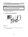
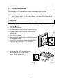
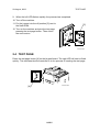
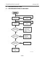
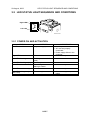
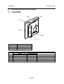
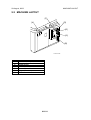
Printer Controller Unit
(UC5)
Trademarks
Microsoft®, Windows®, and MS-DOS® are registered trademarks of Microsoft
Corporation in the United States and /or other countries.
Other product names used herein are for identification purposes only and may be
trademarks of their respective companies. We disclaim any and all rights involved
with those marks.
Symbols
This manual uses several symbols. The meanings of those symbols are as follows:
☛
!
"
#
$
See or Refer to
Clip ring
E-ring
Screw
Connector
TABLE OF CONTENTS
1. INSTALLATION ..................................................................... UC5-1
2. REPLACEMENT AND ADJUSTMENT................................... UC5-2
2.1 CONTROLLER BOARD MEMORY....................................................... UC5-2
2.2 VIDEO I/F BOARD................................................................................ UC5-3
2.3 LOAD PROGRAM................................................................................. UC5-4
2.4 TEST PAGE.......................................................................................... UC5-5
3. TROUBLESHOOTING ........................................................... UC5-6
3.1 TROUBLESHOOTING FLOWCHART .................................................. UC5-6
3.2 LED STATUS LIGHT SEQUENCE AND CONDITIONS ....................... UC5-7
3.2.1 POWER ON AND ACTIVATION.................................................. UC5-7
3.2.2 TEST PAGE BUTTON................................................................. UC5-8
3.3 PRINTER DRIVER OPERATION.......................................................... UC5-9
4. SERVICE TABLE ................................................................... UC5-9
5. DETAILED DESCRIPTIONS ................................................ UC5-10
5.1 OVERVIEW ........................................................................................ UC5-10
5.2 MACHINE LAYOUT ............................................................................ UC5-11
6. SEPECIFICATIONS ............................................................. UC5-12
29 August, 2003
CONTROLLER BOARD MEMORY
1. INSTALLATION
The HP4 for China (HP4P) is equipped with a standard printer controller unit and
Video I/F board. Connect the printer controller unit to the host computer with a
parallel cable. Then install the printer driver in the host computer.
Host computer
Interface
Operating Systems Supported
Printer Driver
IBM PC/AT compatible PC
IEEE1284B (Compatible, Nibble, ECP)
Windows 95/98/Me, Windows NT4.0,
Windows 2000/XP
Digital Duplicator A3 400 GDI
C249I950.WMF
UC5-1
CONTROLLER BOARD MEMORY
29 August, 2003
2. REPLACEMENT AND ADJUSTMENT
!CAUTION
Before removing any of the controller components, do the following:
1. If the ‘data-in’ lamp on the operation panel is blinking or lit, wait until the
document or report is printed. Then turn off the machine.
2. Turn off the main switch and disconnect the power cord, and the cable.
NOTE: This manual uses these symbols:
Screw: #
Connector: $
2.1 CONTROLLER BOARD MEMORY
[B]
[A]
[D]
[C]
C249R951.WMF
[A]: Cover
[B]: Keypad board
NOTE: When you attach the connector [C] make sure to attach it in the correct
direction and position [D].
UC5-2
29 August, 2003
VIDEO I/F BOARD
[A]
[D]
[A]
[C]
[A]
[B]
C249R952.WMF
[A]: Connector
[B]: Printer controller board
[C]: SIMM module
NOTE: The twisted portion of the harness [D] should fit loosely and close to the
controller board.
2.2 VIDEO I/F BOARD
[A]
C249R953.WMF
[A]: Video I/F Board
UC5-3
LOAD PROGRAM
29 August, 2003
2.3 LOAD PROGRAM
This procedure is for upgrading the system firmware for the controller.
NOTE: If the controller does not start up after a firmware update, try to download
the firmware again. If it still does not work, you may need to replace the
flash ROM on the printer controller board.
!CAUTION
Do not turn off the machine while downloading the firmware.
1. Before downloading new firmware, print the test page. Then check the current
version. (☛ 2.6)
2. Turn off the machine.
3. Remove the rear cover and the controller cover.
4. Put the jumper next to the flash ROM into the
position [A].
[A]
5. Turn on the machine.
6. Boot up the PC and access the MS-DOS prompt
or Command Prompt.
7. Use COPY command to update the flash ROM.
e.g. “copy file_name LPT1:” LPT1 is the
connected port.
C249R957.WMF
8. While the flash ROM is updating, the
left LED [B] on the control button
board is continuously on.
[B]
UC5-4
C249R954.WMF
29 August, 2003
TEST PAGE
9. When the left LED flashes rapidly, the process has completed.
10. Turn off the machine.
11. Put the jumper into the off position [C] next to
the flash ROM.
[C]
12. Turn on the machine and print the test page
pressing the test page button. Then check
the new version.
C249R958.WMF
2.4 TEST PAGE
Press the test page button [A] on the keypad board. The right LED will start to flash
quickly. This indicates that the controller is in the process of creating the test page.
[A]
C249R954.WMF
UC5-5
TROUBLESHOOTING FLOWCHART
29 August, 2003
3. TROUBLESHOOTING
3.1 TROUBLESHOOTING FLOWCHART
Problem
Engine works
normally
No
Recover from the
error
No
Recover from the
error
Yes
LED status is
normal
Yes
Test page is
printed normal
!
!
!
!
!
No
Controller Board
Program ROM
Video Cable
Video I/F Board
Cable
Yes
Is print test
result normal?
Yes
Printer Driver
Setting, or
Application
Software Setting.
No
Printed normal
with DOS
Yes
Printer Driver Fault
No
Printer Port of
Computer, Printer
Cable
C249T950.WMF
UC5-6
29 August, 2003
LED STATUS LIGHT SEQUENCE AND CONDITIONS
3.2 LED STATUS LIGHT SEQUENCE AND CONDITIONS
Right LED
Left LED
C249T951.WMF
3.2.1 POWER ON AND ACTIVATION
STATUS
All LEDs are off
CONTENTS
No power supply
Right LED is on
Power on
Left LED is flashing
Self-diagnostic test before
ready
Receiving data
-
Transferring data
Making a master
Idle
-
Left LED is flashing rapidly
Left LED is on continuously
Left LED is continuously off
Left LED flashing slowly
and evenly
Error on engine
UC5-7
CHECK POINT
• No AC power.
• AC cord not properly
connected.
• Power supply failure in the
controller.
-
-
• Check message on operation
panel.
LED STATUS LIGHT SEQUENCE AND CONDITIONS
29 August, 2003
3.2.2 TEST PAGE BUTTON
STATUS
Left LED is flashing
CONTENTS
Receiving data
Left LED is on
Making a master
-
Left LED continuously on
Printing
-
Left LED flashes and goes
off. LED stays off.
No response from the
engine.
Left LED flashes slowly and
evenly.
Engine error
UC5-8
CHECK POINT
-
• Turn off the engine and turn it
back on.
• Check if the controller is
properly connected to the
engine.
• Check if the engine is online.
• Check if SIMM card is
positioned correctly.
• Check error message on the
engine.
• Check if the controller is
properly connected to the
engine.
29 August, 2003
PRINTER DRIVER OPERATION
3.3 PRINTER DRIVER OPERATION
If the Windows test page does not print or does not look right, check the printer
driver operation using these steps:
1. Select the details tab in the properties menu of the printer driver.
2. Change port connection to “File:”
3. Click on the apply button. Then select the general tab and click on the print test
page button.
4. Set the file name (e.g. test.prn). Then set the disk/directory location. Save the
file.
5. Click “YES” when the message pops up and asks whether the test page printed
correctly.
6. Access the MS-DOS prompt or Command Prompt.
7. Check that the engine and controller are ready for printing. Then execute the
following command at the MS-DOS prompt or Command Prompt. “copy /b
test.prn lpt1”
NOTE: 1) Always input “/b” after copy command.
2) The above example applies if the file name saved in the step 4 is
“test.prn”.
3) If the controller is connected to a second port of PC, replace “lpt1”
with “lpt2”.
8. Input “exit”. Then exit from the MS-DOS prompt or Command Prompt.
9. If the has printed correctly, return the printer driver to the previous printer port
from port “File:”.
4. SERVICE TABLE
There is no SP mode for printer controller unit.
UC5-9
OVERVIEW
29 August, 2003
5. DETAILED DESCRIPTIONS
5.1 OVERVIEW
[A]
[B]
[C]
[D]
[E]
C249D950.WMF
DESCRIPTION
CONTROLLER
CPU
Analog Devices ADSP chip
RAM
16MB (SIMM)
Flash ROM
1MB EPROM
REF.
A
B
C
D
E
CONNECTOR
Name
Configuration
IEEE1284 I/F
26-pin socket
Engine Interface
26-pin socket
Power connector
4-pin socket
SIMM Interface
72-pin SIMM
Upgrade firmware jumper
2-pin
UC5-10
DESCRIPTION
To IEEE1284 Interface
To video I/F board
To power cable
For connecting the SIMM module
Upgrading controller firmware
29 August, 2003
MACHINE LAYOUT
5.2 MACHINE LAYOUT
[F]
[D]
[A]
[E]
[C]
[B]
C249D951.WMF
REF.
A
B
C
D
E
F
COMPONENT
Video Interface Board
SIMM Module
IEEE1284 Interface
Control Button Board
Keypad Board
Printer Controller Board
UC5-11
MACHINE LAYOUT
29 August, 2003
6. SEPECIFICATIONS
CONTROLLER TYPE
Configuration
Printer Language
Print Resolution
Memory (RAM)
Resident Fonts
Host Interface
EMBEDDED
Internal embedded controller
GDI
400dpi
16MB (SIMM)
None
IEEE1284B (Compatible, Nibble, ECP)
Host PC
Operating Systems Supported
IBM PC/AT compatible PC
Windows 95/98/Me, Windows NT4.0 (*1), Windows
2000/XP
Digital Duplicator A3 400 GDI
Printer Driver
*1: The Printer drivers for Windows NT4.0 are only for the Intel x86 platform. There
is no Windows NT4.0 printer driver for the PowerPC, Alpha, or MIPS platforms.
UC5-12