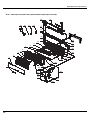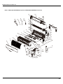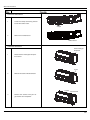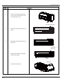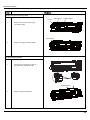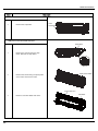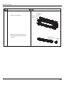
1
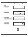
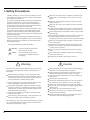
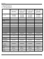
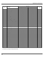
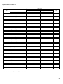
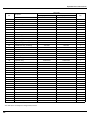
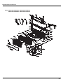
Change for Life
Service Manual
MODELS: GWH(09)MA-K3DNA2B/I
GWH(12)MB-K3DNA2B/I
GWH(18)MC-K3DNA2B/I
GWH(07)MA-K3DNA3B/I
GWH(09)MA-K3DNA3B/I
GWH(12)MB-K3DNA3B/I
GWH(18)MC-K3DNA3B/I
GWH(09)MA-K3DNB8B/I
GWH(12)MB-K3DNB8B/I
GWH(07)MA-K3DNC5B/I
GWH(09)MA-K3DNC5B/I
GWH(12)MB-K3DNC5B/I
GWH(18)MC-K3DNC5B/I
GWH(07)MA-K3DNB8B/I(Cold plasma)
GWH(09)MA-K3DNB8B/I(Cold plasma)
GWH(12)MB-K3DNB8B/I(Cold plasma)
GWH(18)MC-K3DNB8B/I(Cold plasma)
GREE ELECTRIC APPLIANCES,INC.OF ZHUHAI
Table Contents
Summary and Features....................................................................................1
Part 1 Safety Precautions ...........................................................................................2
Part 2 Specifications..................................................................................................... 3
2.1 Unit Specifications ..................................................................................................3
2.2 Capacity Variation Ratio According to Temperature...............................................4
Part 3 Construction Views.........................................................................................5
Part 4 Refrigerant System Diagram......................................................................6
Part 5 Schematic Diagram .........................................................................................7
5.1 Electrical Data.........................................................................................................7
5.2 Electrical Wiring.......................................................................................................7
5.3 Printed Circuit Board...............................................................................................9
Part 6 Function and Control ....................................................................................11
6.1 Remote Control Operations ...................................................................................11
6.2 Description of Each Control Operation.................................................................. 15
Part 7 Installation Manual..........................................................................................18
7.1 Notices for Installation............................................................................................18
7.2 Installation Drawing........................................................................................19
7.3 Install Indoor Unit..................................................................................................20
7.4 Check After Installation and Test Operation..........................................................21
7.5 Installation and Maintenance of Healthy Filter....................................................... 22
Part 8 Exploded Views and Parts List ............................................................... 23
Part 9 Troubleshooting ................................................................................................ 39
.....................................................................................................39
9.1 Malfunction Display
9.2 How to Check Simply the Main Part ......................................................................... 42
Part10 Removal Procedure.........................................................................................48
Summary and features
Summary and features
Indoor Unit
GWH(09)MA-K3DNA2B/I
GWH(12)MB-K3DNA2B/I
GWH(18)MC-K3DNA2B/I
GWH(07)MA-K3DNA3B/I
GWH(09)MA-K3DNA3B/I
GWH(12)MB-K3DNA3B/I
GWH(18)MC-K3DNA3B/I
GWH(09)MA-K3DNB8B/I
GWH(12)MB-K3DNB8B/I
GWH(07)MA-K3DNB8B/I(Cold plasma)
GWH(09)MA-K3DNB8B/I(Cold plasma)
GWH(12)MB-K3DNB8B/I(Cold plasma)
GWH(18)MC-K3DNB8B/I(Cold plasma)
GWH(07)MA-K3DNC5B/I
GWH(09)MA-K3DNC5B/I
GWH(12)MB-K3DNC5B/I
GWH(18)MC-K3DNC5B/I
Remote Controller
YT1F
FAN
MODE
I FEEL
CLOCK
TIMER
ON
X-FAN
TEMP
TIMER
OFF
TURBO
SLEEP
LIGHT
1
Safety Precautions
1.Safety Precautions
Installing, starting up, and servicing air conditioner can be
hazardous due to system pressure, electrical components,
and equipment location, etc.
Only trained, qualified installers and service personnel are
allowed to install, start-up, and service this equipment.
Untrained personnel can perform basic maintenance functions such as cleaning coils. All other operations should
be performed by trained service personnel.
Make sure the outdoor unit is installed on a stable, level
surface with no accumulation of snow, leaves, or trash
beside.
When handling the equipment, observe precautions in the
manual and on tags, stickers, and labels attached to the
equipment. Follow all safety codes. Wear safety glasses
andwork gloves. Keep quenching cloth and fire extinguisher
nearby when brazing.
Follow all the installation instructions to minimize the risk
of damage from earthquakes, typhoons or strong winds.
Read the instructions thoroughly and follow all warnings or
cautions in literature and attached to the unit. Consult local
building codes and current editions of national as well as
local electrical codes.
Recognize the following safety information:
Warning
Incorrect handling could result in
personal injury or death.
Caution
Incorrect handling may result in
minor injury,or damage to product
or property.
Warning
All electric work must be performed by a licensed technician
according to local regulations and the instructions given in
this manual.
Before installing, modifying, or servicing system, main
electrical disconnect switch must be in the OFF position.
There may be more than 1 disconnect switch. Lock out
and tag switch with a suitable warning label.
Never supply power to the unit unless all wiring and tubing are completed, reconnected and checked.
This system adopts highly dangerous electrical voltage.
Incorrect connection or inadequate grounding can cause
personal injury or death. Stick to the wiring diagram and
all the instructions when wiring.
Have the unit adequately grounded in accordance with
local electrical codes.
Have all wiring connected tightly. Loose connection may
lead to overheating and a possible fire hazard.
All installation or repair work shall be performed by your dealer or a specialized subcontractor as there is the risk of fire,
electric shock, explosion or injury.
2
Make sure the ceiling/wall is strong enough to bear the
weight of the unit.
Make sure the noise of the outdoor unit does not disturb
neighbors.
Avoid contact between refrigerant and fire as it generates
poisonous gas.
Apply specified refrigerant only. Never have it mixed with
any other refrigerant. Never have air remain in the
refrigerant line as it may lead to rupture and other hazards.
Make sure no refrigerant gas is leaking out when installation is completed.
Should there be refrigerant leakage, the density of refrigerant in the air shall in no way exceed its limited value,
or it may lead to explosion.
Keep your fingers and clothing away from any moving
parts.
Clear the site after installation. Make sure no foreign objects are left in the unit.
Always ensure effective grounding for the unit.
Caution
Never install the unit in a place where a combustible gas
might leak, or it may lead to fire or explosion.
Make a proper provision against noise when the unit is
installed at a telecommunication center or hospital.
Provide an electric leak breaker when it is installed in a
watery place.
Never wash the unit with water.
Handle unit transportation with care. The unit should not
be carried by only one person if it is more than 20kg.
Never touch the heat exchanger fins with bare hands.
Never touch the compressor or refrigerant piping without
wearing glove.
Do not have the unit operate without air filter.
Should any emergency occur, stop the unit and disconnect the power immediately.
Properly insulate any tubing running inside the room to
prevent the water from damaging the wall.
Specifications
2.Specifications
2.1 Unit Specifications
Model
GWH(07)MA-K3DNA3B/I
GWH(07)MA-K3DNC5B/I
GWH(07)MAK3DNB8B/I(Cold plasma)
GWH(09)MA-K3DNA2B/I GWH(12)MB-K3DNA2B/I
GWH(18)MC-K3DNA2B/I
GWH(09)MA-K3DNA3B/I GWH(12)MB-K3DNA3B/I
GWH(18)MC-K3DNA3B/I
GWH(09)MA-K3DNB8B/I GWH(12)MB-K3DNB8B/I
GWH(18)MC-K3DNC5B/I
GWH(09)MA-K3DNC5B/I GWH(12)MB-K3DNC5B/I
GWH(18)MCGWH(12)MBGWH(09)MAK3DNB8B/I(Cold plasma)
K3DNB8B/I(Cold plasma) K3DNB8B/I(Cold plasma)
CB171N0400
CB179N00900
CB174N02100
CB181N02700
CB171N0340
CB174N01900
CB179N01000
CB174N01901
CB181N02800
CB171N0350
CB174N02000
CB179N01100
CB174N02001
CB181N02900
CB171N0360
CB179N01200
CB174N02200
Capacity(Cooling)(W )
2100
2600
3500
5300
Capacity(Heating)(W )
2600
2800
3800
5800
1200/1050/920/730
1260/1050/920/730
(1260)/1070/900/730
1350/1200/1050/900
450
500
630
850
10
10
20
20
/
/
/
/
1
1
1
1.5
0.23
0.23
0.37
0.48
Cross flow fan
Cross flow fan
Cross flow fan
Cross flow fan
ĭ85X596
ĭ85X596
ĭ92X645
ĭ98X710
Product Code
Fan Motor Speed (r/min)
(SH/H/M/L)
Airflow(m ³/h)
Output of Fan Motor (W )
Input Power of Heater
(W)
Fan Motor Capacitor (ȝF)
Fan Motor RLA(A)
Fan Type
Diameter-Length (mm)
Evaporator
Pipe Diameter (mm)
Row-Fin Gap(m m )
Coil length (l)Xheight
(H)X coil width (L)
Swing Motor Model
Output of Swing Motor
(W)
Fuse (A)
Sound Pressure Level dB
(A) (SH/H/M/L/SL)
Sound Power Level dB
(A) (SH/H/M/L/SL)
Dimension (WXHXD) (
mm)
Dimension of Carton
Box (LXWXH)
Dimension of Package
(LXWXH )( mm)
Liquid connections
Diameter
Gas connections
Diameter
Net Weight /Gross
Weight (kg)
Aluminum fin-copper tube Aluminum fin-copper tube Aluminum fin-copper tube Aluminum fin-copper tube
ĭ7
ĭ7
ĭ7
ĭ7
2-1.5
2-1.5
2-1.4
2-1.4
581X264X25.4
581X264X25.4
645X267X25.4
715X304.8X25.4
MP24AA
MP24AA
MP24AA
MP28VB
1.5
1.5
1.5
2
PCB 3.15A
PCB 3.15A
PCB 3.15A
PCB 3.15A
36/34/31/28/-
37/34/31/28/-
38/34/32/30/-
46/43/40/36/-
46/44/41/38/-
47/44/41/38/-
48/44/42/40/-
56/53/40/36/-
790X265X170
790X265X170
845X275X180
940X298X200
870X248X355
870X248X355
915X255X355
1010X285X380
873X251X370
873X251X370
918X258X370
1013X288X395
ĭ6(1/4ͳ)
ĭ6(1/4ͳ)
ĭ6(1/4ͳ)
ĭ6(1/4ͳ)
ĭ9.52(3/8ͳ)
ĭ9.52(3/8ͳ)
ĭ9.52(3/8”)
ĭ12(1/2ͳ)
9/12
9/12
10/13
13/17
The above data is subject to change without notice. Please refer to the nameplate of the unit.
3
Specifications
2.2 Noise Criteria Curve Tables for Both Models
60
50
.
Noice/dB(A)
40
.
.
30
.
20
10
0
Low
Middle
Indoor Fan Motor Rotating Speed
4
High
Super High
Constrction views
3. Construction Views
D
H
W
Q
R
S
7K&09K
ĭ;
Q
R
S
.
ĭ;
Q
R
S
18K
ĭ;
Model(mm)
W
H
D
Q
R
S
7K&09K
790
6
170
3
60
10
1K
84
7
180
134
40
171
18K
940
98
00
108
694
138
5
Refrigerant System Diagram
4. Refrigerant System Diagram
Cooling & Heating Models
outdoor
indoor
filter
A heat exchanger
A3
A1
filter
B heat exchanger
fan
A2
outdoor heat exchanger
4-way valve
B3
B1
SP
filter
B2
high pressure switch
Note: Not available for 14K/18K
model
discharge silencer
C heat exchanger
C3
C1
filter
D3
C2
D1
filter
D2
gas -liquid separator
Note: Not available for 14K/18K model
A1:A-unit electronic expansion valve B1:B-unit electronic expansion valve
C1:C-unit electronic expansion valve D1:D-unit electronic expansion valve
A2:A-unit gas pipe temperature sensor B2:B-unit gas pipe temperature sensor
C2:C-unit gas pipe temperature sensor D2:D-unit gas pipe temperature sensor
A3:A-unit liquid pipe temperature sensor B3:B-unit liquid pipe temperature sensor
C3:C-unit liquid pipe temperature sensor D3:D-unit liquid pipe temperature sensor
6
inverter compressor
D heat exchanger
discharge temperature
sensor
Schematic Diagram
5. Schematic Diagram
5.1 Electrical Data
Meaning of marks
Symbol
Color symbol
Symbol
Color symbol
WH
WHITE
BN
BROWN
YE
BLUE
YELLOW
BU
RD
RED
BK
BLACK
YEGN
OG
SAT
YELLOW GREEN
ORANGE
OVERLOAD
VT
VIOLET
PROTECTIVE EARTH
COMPRESSOR
COMP
5.2 Electrical Wiring
For 07/09/12K Unit
TUBE
TEM.SENSOR
0
0
RT2
RT1
TUBE
M1
ROOM
PGF
PG
N
COM-OUT
AC-L
AP2
JUMP
SWING-UD
3BK
XT
N(1)
2
3
2BN
BU
BK
BN
YEGN
4YEGN
HEALTH-N
HEALTH-L
BU
AP1
SWING
MOTOR
EVAPORATOR
PE
RD
M2
RECEIVER AND
DISPLAY BOARD
1BU
Outdoor Unit
CAP
DISP1 DISP2
FAN
MOTOR
ROOM
TEM.SENSOR
COOL PLASMA
GENERATOR
NOTE:The parts with broken line is applicable
to the models with COOL PLASMA GENERATOR
7
Schematic Diagram
For 18K Unit
TUBE
TEM.SENSOR
0
0
RT2
RT1
CAP
JUMP
DISP1 DISP2
M1
PG
ROOM
AP2
SWING-UD
M2
RECEIVER AND
DISPLAY BOARD
N
COM-OUT
AC-L
SWING
MOTOR
1BU
3BK
2BN
XT
BU
2 BK
3 BN
YEGN
N(1)
4YEGN
PE
EVAPORATOR
HEALTH-L
AP1
PGF
HEALTH-N
RD
BU
COOL PLASMA
GENERATOR
(optional)
These circuit diagrams are subject to change without notice, please refer to the one supplied with the unit.
8
Outdoor Unit
TUBE
FAN MOTOR
ROOM
TEM.SENSOR
Schematic Diagram
5.3 Printed Circuit Board
For 07/09/12K Unit
TOP VIEW
3
4
5
6
7
8
2
9
1
13
10
12
1
2
Power supply live wire
connector
Power supply neutral wire
connector
5
6
3
Fan capacitor
7
4
Health function
terminal(optional)
8
Indoor fan wire terminal
indoor and outdoor unit
communication wire terminal
Up & down swing control
terminal
Indoor fan feedback terminal
11
9
Jumper cap terminal
10
Display panel terminal
11
12
13
Indoor ambient temperature
sensor
Indoor pipe temperature
sensor
Protective tube
BOTTOM VIEW
9
Schematic Diagram
TOP VIEW
For 18K Unit
3
4
5
6
2
7
8
1
1
2
3
9
14
10
11
4
Fan capacitor
5
PG motor connector
6
Auto button
7
Up & down swing connector
8
PG motor fan feedback terminal
9
Display panel connector
10
Indoor and outdoor unit
communication wire terminal
11
Jumper cap terminal
12
13
14
13
BOTTOM VIEW
10
12
Power supply live wire
connector
Power supply neutral wire
connector
Protective tube
Indoor ambient temperature
sensor
Indoor pipe temperature sensor
Health function
terminal(optional)
Function and Control
6. Function and Control
6.1 Remote Control Operations
1
2
3
4
1
2
4
6
3
5
5
6
7
8
7
9
10
11
12
13
14
15
16
17
ON/OFF
Press it to start or stop operation.
-:
Press it to decrease temperature setting.
+:
Press it to increase temperature setting.
FAN
Press it to set fan speed.
MODE
Press it to select operation mode (AUTO/COOL/DRY/FAN/HEAT).
I FEEL
Press it to set HE ALTH function
8
9
10
Press it to set AIR function.
CLOCK
Press it set clock.
TIMER ON
Press it to set auto-on timer.
11
12
13
14
15
16
17
Press it set swing angle.
X-FAN (X-FAN is the alternative expression of BLOW for the purpose of understanding.)
TEMP
TIMER OFF
Press it to set auto-off timer
TURBO
SLEEP
LIGHT
Press it to turn on/off the light.
31 30 29
28
27
26
25
24
18
18
MODE icon:
If MODE button is pressed, current operation mode icon
models) will show.
19 20 21 22
(AUTO),
( COOL),
23
(DRY),
(FAN) or
(HEAT only for heat pump
11
Function and Control
19
SLEEP icon :
is displayed by pressing the SLEEP button. Press this button again to clear the display.
20
TEMP icon:
Pressing TEMP button,
(set temperature),
21
Up & down swing icon:
22
LIGHT icon:
23
LOCK icon:
24
SET TIME display:
(ambient temperature),
(outdoor ambient temperature) and blank is displayed circularly.
is displayed when pressing the up & down swing button. Press this button again to clear the display.
is displayed by pressing the LIGHT button. Press LIGHT button again to clear the display.
is displayed by pressing "+" and “-” buttons simultaneously. Press them again to clear the display.
After pressing TIMER button, ON or OFF will blink.This area will show the set time.
25
TURBO icon:
is displayed when pressing the TURBO button.Press this button again to clear the display.
26
DIGITAL display:
This area will show the set temperature. In SAVE mode,"SE" will be displayed. During defrosting operation, “H1” will be displayed.
27
AIR icon:
28
I FEEL icon:
29
FAN SPEED display:
is displayed when pressing the AIR button.Press this button again to clear the display.
is displayed when pressing the I FEEL button. Press this button again to clear the display.
Press FAN button to select the desired fan speed setting (AUTO Low-Med-High).Your selection will be displayed in the LCD windows,
except the AUTO fan speed.
30
HEALTH icon:
31
X-FAN icon:
is displayed when pressing the HEALTH button. Press this button again to clear the display.
is displayed when pressing the X-FAN button. Press this button again to clear the display.
1
ON/OFF:
Press this button to turn on the unit .Press this button again to turn off the unit.
2
-:
Press this button to decrease set temperature. Hold it down for above 2 seconds to rapidly decrease set temperature. In AUTO mode, set
temperature is not adjustable.
3
+:
Press this button to increase set temperature. Hold it down for above 2 seconds to rapidly increase set temperature. In AUTO mode, set temperature is not adjustable.
4
FAN :
This button is used for setting Fan Speed in the sequence that goes from AUTO,
,
,
to then back to Auto.
AUTO
Low speed
Medium speed
High speed
5 MODE :
Each time you press this button, a mode is selected in a sequence that goes from AUTO,COOL,DRY, FAN,and HEAT *, as the following:
AUTO
COOL
DRY
FAN
HEAT *
*Note: Only for models with heating function.
After energization, AUTO mode is defaulted. In AUTO mode, the set temperature will not be displayed on the LCD, and the unit will automatically select the suitable operation mode in accordance with the room temperature to make indoor room comfortable.
12
Function and Control
6
I FEEL:
Press this button to turn on I FEEL function. The unit automatically adjust temperature according to the sensed temperature. Press this button
again to cancel I FEEL function.
7
Press this button to set HEALTH function ON or OFF. After the unit is turned on, it defaults to HEALTH function ON.
8
Press this button to select AIR function ON or OFF.
9
CLOCK :
Pressing CLOCK button,
blinks. Within 5 seconds, pressing + or - button adjusts the present time. Holding down either button above 2
seconds increases or decreases the time by 1 minute every 0.5 second and then by 10 minutes every 0.5 second. During blinking after
setting, press CLOCK button again to confirm the setting, and then
10
will be constantly displayed.
TIMER ON :
Press this button to initiate the auto-ON timer. To cancel the auto-timer program, simply press this button again.
After pressing this button,
disappear sand " ON " blink s . 00:00 is displayed for ON time setting. Within 5 seconds, press + or - button to
adjust the time value. Every press of either button changes the time setting by 1 minute. Holding down either button rapidly changes the time
setting by 1 minute and then 10 minutes. Within 5 seconds after setting, press TIMER ON button to confirm.
11
Press this button to set up & down swing angle, which circularly changes as below:
AUTO
This remote controller is universal. If any command , or is sent out,
, , the unit will carry out the command as
indicates the guide louver swings as:
12
X-FAN:
Pressing X -FAN button in COOL or DRY mode, the icon
is displayed and the indoor fan will continue operation for 10 min utes in order to
dry the indoor unit even though you have turned off the unit. After energization, X-FAN OFF is defaulted. X-FAN is not available in AUTO,
FAN or HEAT mode.
13
TEMP:
Press this button, could select displaying the indoor setting temperature or indoor ambient temperature.When the indoor unit firstly power on
it will display the setting temperature, if the temperature's displaying status is changed from other status to"
",displays the ambient temp-
erature, 5s later or within 5s, it receives other remote control signal that will return to display the setting temperature. if the users haven't set
up the temperature displaying status,that will display the setting temperature.
14
TIMER OFF :
Press this button to initiate the auto-off timer. To cancel the auto-timer program, simply press the button again.TIMER OFF setting is the
same as TIMER ON.
15
TURBO:
Press this button to activate / deactivate the Turbo function which enables the unit to reach the preset temperature in the shortest time. In
COOL mode, the unit will blow strong cooling air at super high fan speed. In HEAT mode, the unit will blow strong heating air at super high
fan speed.
16
SLEEP:
Press this button to go into the SLEEP operation mode. Press it again to cancel this function. This function is available in COOL, HEAT (Only
for models with heating function) or DRY mode to maintain the most comfortable temperature for you.
17
LIGHT:
Press LIGHT button to turn on the display's light and press this button again to turn off the display's light. If the light is turned on,
played. If the light is tunrned off ,
is dis-
disappears.
13
Function and Control
18
Combination of "+" and "-" buttons: About lock
Press "+ " and "-" buttons simultaneously to lock or unlock the keypad. If the remote controller is locked,
pressing any button,
is displayed. In this case,
blinks three times.
19 Combination of "MODE" and "-" buttons: About switch between Fahrenheit and Centigrade At unit OFF, press "MODE" and "- " buttons
simultaneously to switch between ℃ and ℉
Replacement of Batteries
1.Remove the battery cover plate from the rear of the remote controller.
(As shown in the figure)
2.Take out the old batteries.
3.Insert two new AAA1.5V dry batteries, and pay attention to the polarity.
4. Reinstall the battery cover plate.
★ Notes:
●When replacing the batteries, do not use old or different types of batteries,
otherwise, it may cause malfunction.
●If the remote controller will not be used for a long time, please
remove batteries to prevent batteries from leaking.
●The operation should be performed in its receiving range.
●It should be kept 1m away from the TV set or stereo sound sets.
●If the remote controller does not operate normally, please take the
batteries out and reinsert them after 30 seconds. If it still can't operate properly,
replace the batteries.
14
Sketch map for replacing batteries
Function and Control
6.2 Description of Each Control Operation
I. Basic Operation Mode
1. Cool; 2.Dry; 3.Heat; 4.Auto; 5.Fan
II. Basic Functions
Cooling Only
(1) Under this mode, fan and swing run at preset status, the temperature setting range is 16-30ć.
C
B
A
indoor temperature---target temperature
(2) Under malfunction for outdoor unit and protection stop, the indoor unit runs with the original status, and display malfunction.
(3) The indoor fan stops when the modes conflict with each other.
2. Dry Mode
(1) Under this mode, the indoor fan runs with low speed, and swing runs at preset status, the temperature setting range is 16-30ć.
(2) Under malfunction for outdoor unit and protection stop, the indoor unit runs with the original status, and display malfunction.
3. Heating Mode
(1) Under this mode, the temperature setting range is 16-30ć.
A
target temperature---indoor temperature
B
(2) Working condition and Process of Heating
When the unit is ON and in heating mode, indoor fan starts cold air prevention operation; when the unit is off and the
indoor fan stopped before, it blows residual heat.
(3) Protection Function. The compressor stops as the malfunction (including any temperature sensor malfunction) in
heating mode, the indoor fan runs with blowing residual heat.
4. Working Methods of Auto Mode
1) When Tamb.≥26ć( F) , it operates in Cool mode.
2) For heat pump unit, when Tamb.≤22ć, it operates in Heat mode.
3) When 22ć< Tamb.< 26ć, it operates in auto fan mode upon initial startup of the unit. When changing to auto mode from
other modes, it will keep the previous operation mode (when it enter Dry mode, it operates in auto fan mode.).
5. Fan Mode
Only indoor fan operates in Fan mode. Under auto fan speed, it runs in cooling auto fan mode.
15
Function and Control
III. Other Control
1. Buzzer
The buzzer will give out a beep when the controller is energized, receiving signal from remote controller and auto button.
2. Auto Button
Press this button once, it will operate in Auto mode, and indoor fan operates in Auto fan mode and swing. When the unit is on,
pressing this button will turn off the unit.
3. Auto Fan
a. Auto fan speed in Heat mode
When Tamb.≤Tpreset, the indoor fan operates at high speed;
When Tpreset<Tamb.<Tpreset+2ć, the indoor fan operates at middle speed;
When Tamb≥Tpreset+2ćˈthe indoor fan operates at low speed.
b. Auto fan speed in CooL and Fan mode
When Tamb≥Tpreset+3ćˈthe indoor fan operates at high speed;
When Tpreset<Tamb.<Tpreset+3ć, the indoor fan operates at middle speed;
When Tamb.≤Tpreset+1ć, the indoor fan operates at low speed.
c. The auto fan speed is at low speed in Dry mode.
Note: Under auto fan speed, it will shift between high speed and middle speed, middle speed and low speed, high speed
and low speed, the operation time must be 3.5min at least.
4. Sleep
4.1 The unit will select suitable sleep curve according to set temperature.
4.2 Sleep curve in Heat mode
Tset+3℃
Tset+2℃
Tset+1℃
Tset
1H
2H
3H
4H
4.3 Sleep curve in Cool mode
Tset
Tset-1℃
Tset-2℃
Tset-3℃
1H
2H
3H
4H
5. Timer Function
(1) General Timer:
1.1 Time On: if Timer On is set when the system is,the controller will operate in the original setting mode after reaching the
timer on time. The timer interval is 0.5h, and the setting range is 0.5-24h.
1.2 Timer Off: Timer Off can be set when the unit is on. The unit will be off when timer off time is reahced. The timer
interval is 0.5h, and the setting range is 0.5-24h.
(2) Clock Timer:
2.1 Timer On: If Timer On is set when the system runs, it will continue to run; if Timer On is set when the system is off, the
system will start to run in the original setting mode when timer on time is reached.
2.2 Timer Off: If timer off is set when the system is off, the system keeps stand-by status; if timer off is set when the system
is on, the system stops when reaching timer off time.
16
Function and Control
2.3 Timer Change
Timer On and Timer OFF can be set via remote ON/OFF button. Timer time can be reset and the system will operate according to
the latest setting.
When the unit is on and Timer On and Timer Off are both set, the system will operate according to the set state. When the timer off
time is reached, the system will stop.
When the system stops, and Timer On and Timer Off are both set, the system will remain stop until timer on time is reached. After
that, the unit will operate according to the set mode everyday when the timer on time is reached. When the timer off time is reached,
the system will stop. If timer on time is the same as timer off time, the system will stop.
6. Memory Function
Memory contents: mode, up& down swing, light, set temperature, set fan speed, general timer (but clock timer). After power failure, if
the unit is reenergized, it will operate according to memory contents. If Timer function is not set in the last remote control, the system
will operate according to the last remote control.
If general timer function is set in the last remote control and power failure occurs before timer time is reached, the unit will operate
according to the timer function set in the last remote control. Timer time is calculated after the unit is re-energized.
If general timer function is set in the last remote control and power failure occurs after timer time is reached, the system will operate
according to the memory content before power failure. Timer operation is not memorized.
7. Health Function
When the unit is on and the indoor fan operates, press Health button to start this function (if there is no Health button, health
operation is defaulted). When indoor fan stops or turning of health function by remote controller, health function will be off.
8. I Feel Function
When the controller receives I Feel order, the controller will operate according to the ambient temperature. The remote controller will
send ambient temperature to the controller every 10min. If the controller does not receive the ambient temperature sent by remote
controller for 11min, the air conditioner will operate according the ambient temperature around it. If I Feel function is not set, the air
conditioner will operate according the ambient temperature around it. This function is not memorized upon power failure.
9. Reserved Fahrenheit Temperature
The nixie tube will display the set temperature in Celsius temperature or Fahrenheit Temperature according to the order. Setting
range is 16~30ć (61~86̧). In Auto mode, it will display 25ć (77̧) during cooling and fan operation, and display 20ć (68̧)
during heating operation. For cooling only unit, it displays 25ć (77̧).
The indoor temperature displayed is sent by remote controller, ranging from 0~60ć (32~99̧). If outdoor ambient temperature is
received, the display remains the same. If valid control signal is received, it will display set temperature for 5s and then resume
displaying ambient temperature.
For units with memory function, set temperature will be displayed after re-energizing the unit.
10. Cold Plasma Function
Turning on the cold plasma function with remote controller when the fan operates, this function will act.
Turning off the cold plasma function with remote controller or turning off the fan, this function will end.
12. Defrosting Mode Switch
If there is no H1 displayed, turn on the unit with remote controller and enter “Defrosting mode 1”. When the indoor unit receives
remote control signal, it will send the signal to the outdoor unit.
If there is H1 displayed, turn on the unit with remote controller and enter “Defrosting mode 2”. When the indoor unit receives remote
control signal, it will send the signal to the outdoor unit.
Press mode and auxiliary heating button to switch between “Defrosting mode 1” and “Defrosting mode 2”.
13. Forcible Defrosting Function
When the unit is in Heat mode and set temperature is 16ć, press “+, -, +, -, +, -,” successively for 5s, and the indoor unit will enter
forcible defrosting setting and send the signal to the outdoor unit.
When the indoor unit receives forcible defrosting signal from the outdoor unit, it will exit forcible defrosting setting.
14. Refrigerant Recovery Function
Enter refrigerant recovery mode: turn on the unit within 5 min after energization and at 16ć cooling mode. Press remote controller
light off button successively for 3 times within 3s and the unit will enter refrigerant recovery mode, displaying Fo. The signal will be
sent to the outdoor unit.
Exit refrigerant recovery mode: during refrigerant recovery, if any signal from remote controller is received or refrigerant recovery
lasts for 25min, it will exit this mode.
Action of entering refrigerant recovery mode: the indoor fan will operate in Cool mode. The fan speed is high and set temperature is
16ć. The horizontal louver will be at the smallest angle.
Action of exit refrigerant recovery mode: the indoor fan will operate according to the last remote control setting.
15. Pre-operation Function
When Cool mode at 30ć is set, press “-, +, -, +, -, +” successively for 3s, it will enter pre-operation mode. The signal will be sent to
the outdoor unit.
Pre-operation mode: it performs cooling operation (indoor fan does not operate) and display “dd”.
After exiting pre-operation mode, the indoor unit will stop displaying “dd”. If the signal of “wrong wire connection or expansion valve
malfunction” is received, “dn” will be displayed.
16. Mode Conflict
When the mode of started unit is different from that of operating unit, the indoor unit will display mode conflict code “E7”. The mode
sent to the outdoor unit remains the one received by the remote controller.
17
Installation Manual
7. Installation Manual
7.1 Notices for Installation
Caution
1.The unit should be installed only by authorized service center according to local or government regulations and in compliance with
this manual.
2.Before installing, please contact with local authorized maintenance center. If the unit is not installed by the authorized service center,
the malfunction may not be solved due to incovenient contact between the user and the service personnel.
3.When removing the unit to the other place, please firstly contact with the local authorized service center.
4.Warning: Before obtaining access to terminals, all supply circuits must be disconnected.
5.For appliances with type Y attachment, the instructions shall contain the substance of the following. If the supply cord is damaged, it
must be replaced by the manufacturer, its service agent or similarly qualified persons in order to avoid a hazard.
6.The appliance must be positioned so that the plug is accessible.
7.The temperature of refrigerant line will be high; please keep the interconnection cable away from the copper tube.
8.The instructions shall state the substance of the following:
This appliance is not intended for use by persons(including children)with reduced physical, sensory or mental capabilities, or lack
of experience and knowledge, unless they have been given supervision or instruction concerning use of the appliance by a person
responsible for their safety.
Children should be supervised to ensure that they do not play with the appliance.
7.1.1 Installation Site Instructions
Proper installation site is vital for correct and efficient operation of the unit. Avoid the following sites where:
●strong heat sources, vapours, flammable gas or volatile liquids are emitted.
●high-frequency electro-magnetic waves are generated by radio equipment, welders and medical equipment.
●salt-laden air prevails (such as close to coastal areas).
●the air is contaminated with industrial vapours and oils.
●the air contains sulphures gas such as in hot spring zones.
●corrosion or poor air quality exists.
7.1.2 Installation Site of Indoor Unit
1.The air inlet and outlet should be away from the obstructions. Ensure the air can be blown through the whole room.
2.Select a site where the condensate can be easily drained out, and where it is easily connected to outdoor unit.
3.Select a place where it is out of reach of children.
4.Select a place where the wall is strong enough to withstand the full weight and vibration of the unit.
5.Be sure to leave enough space to allow access for routine maintenance. The installation site should be 250cm or more above the
floor.
6.Select a place about 1m or more away from TV set or any other electric appliance.
7.Select a place where the filter can be easily taken out.
8.Make sure that the indoor unit is installed in accordance with installation dimension instructions.
9.Do not use the unit in the laundry or by swimming pool etc.
7.1.3 Safety Precautions for Electric Appliances
1.A dedicated power supply circuit should be used in accordance with local electrical safety regulations.
,
2.Don t drag the power cord with excessive force.
3.The unit should be reliably earthed and connected to an exclusive earth device by the professionals.
4.The air switch must have the functions of magnetic tripping and heat tripping to prevent short circuit and overload.
5.The minimum distance between the unit and combustive surface is 1.5m.
6.The appliance shall be installed in accordance with national wiring regulations.
7.An all-pole disconnection switch with a contact separation of at least 3mm in all poles should be connected in fixed wiring.
Note:
●Make sure the live wire, neutral wire and earth wire in the family power socket are properly
connected. There should be reliable circuit in the diagram.
●Inadequate or incorrect electrical connections may cause electric shock or fire.
18
Installation Manual
7.1.4 Earthing Requirements
1.Air conditioner is type I electric appliance. Please ensure that the unit is reliably earthed.
2.The yellow-green wire in air conditioner is the earthing wire which can not be used
for other purposes. Improper earthing may cause electric shock.
3.The earth resistance should accord to the national criterion.
4.The power must have reliable earthing terminal. Please do not connect the earthing wire with the following:
ķ Water pipe ĸ Gas pipe Ĺ Contamination pipe
ĺ Other place that professional personnel consider is unreliable
5. The model and rated values of fuses should accord with the silk print on fuse cover or related PCB.
7.2 Installation Drawing
Space to the ceiling
15cm
Above
Space to the wall
15cm Above
15cm Above
Space to the wall
300cm
Above
250cm
Above
Air outlet side
Space to the floor
The dimensions of the space necessary for proper
installation of the unit include the minimum
permissible distances to adjacent parts.
19
Installation Manual
7.3 Install Indoor Unit
7.3.1 Installation of Mounting Plate
0RXQWLQJSODWHVKRXOGEHLQVWDOOHGKRUL]RQWDOO\$VWKHZDWHUWUD\
VRXWOHWIRUWKHLQGRRUXQLWLVWZRZD\
W\SHGXULQJLQVWDOODWLRQWKHLQGRRUXQLWVKRXOGVOLJKWO\VODQWWRZDWHUWUD\
VRXWOHWIRUVPRRWKGUDLQDJHRI
FRQGHQVDWH
)L[WKHPRXQWLQJSODWHRQWKHZDOOZLWKVFUHZV
%HVXUHWKDWWKHPRXQWLQJSODWHKDVEHHQIL[HGILUPO\HQRXJKWRZLWKVWDQGDERXWNJ0HDQZKLOHWKH
ZHLJKWVKRXOGEHHYHQO\VKDUHGE\HDFKVFUHZ
07&09K UNIT:
12K UNIT:
Wall
Wall
Wall
Wall
$ERYH
IURP
WKHZDOO
ĭ
Wall
$ERYH
IURP
WKHZDOO
ĭ
$ERYH
IURP
WKHZDOO
ĭ
ĭ
Left
Right
18K UNIT:
Wall
$ERYH
IURP
WKHZDOO
Left
Right
Wall
Wall
Wall
$ERYH
IURP
WKHZDOO
ĭ
$ERYH
IURP
WKHZDOO
ĭ
Left
Right
,QGRRU
7.3.2 Drill Piping Hole
2XWGRRU
Wall pipe
0DNHWKHSLSLQJKROHɎLQWKHZDOl DWDVOLJKWGRZQZDUGVODQWWRWKH
RXWGRRUVLGH
,QVHUWWKHSLSLQJKROHVOHHYHLQWRWKHKROHWRSUHYHQWWKHFRQQHFWLRQSLSLQJ
and ZLULQg IURm being damaged ZKHn passing WKURXJh the hole.
Seal pad
ĭ
7.3.3 Installation of Drain Hose
&RQQHFWWKHGUDLQKRVHWRWKHRXWOHWSLSHRIWKHLQGRRUXQLW%LQGWKHMRLQWZLWKUXEEHUEHOW
3XWWKHGUDLQKRVHLQWRLQVXODWLQJWXEH
outlet pipe of
LQGRRUXQLW
GUDLQKRVH
outlet pipe of
LQGRRUXQLW
:UDSWKHLQVXODWLQJWXEHZLWKZLGHUXEEHUEHOWWRSUHYHQW
WKHVKLIWRILQVXODWLQJWXEH6ODQWWKHGUDLQKRVHGRZQZDUG
VOLJKWO\IRUVPRRWKGUDLQDJHRIFRQGHQVDWH
UXEEHUEHOW
outlet pipe of
LQGRRUXQLW
GUDLQKRVH
UXEEHUEHOW insulating tube
Note: The insulating tube should be connected reliably with
the sleeve outside the outlet pipe. The drain hose should be
slanted downward slightly, without distortion, bulge or
fluctuation. Do not put the outlet in the water.
UXEEHUEHOW
outlet pipe of
LQGRRUXQLW
FRQQHFWHG
bulge
Flooded
7.3.4 Connecting Indoor and Outdoor Electric Wires
2SHQWKHIURQWSDQHO
5HPRYHWKHZLULQJFRYHUDVVKRZQLQ)LJ
0DNHWKHSRZHUFRQQHFWLRQFRUGSDVVWKURXJKWKHKROHDWWKHEDFNRILQGRRUXQLW
5HLQVWDOOWKHFRUGDQFKRUDJHDQGZLULQJFRYHU
5HLQVWDOOWKHIURQWSDQHO
:LULQJ&RYHU
1
2
3
blue EODFN EURZQ
\HOORZ
JUHHQ
RXWGRRUXQLWFRQQHFWLRQ
Fig.6
20
insulating tube
GLVWRUWLRQ
Installation Manual
NOTE:
All wires between indoor and outdoor units must be connected by the qualified electric contractor.
● Electric wires must be connected correctly. Improper connection may cause malfunction.
● Tighten the terminal screws tightly.
● After tightening the screws, pull the wire sligltly to confirm whether it's firm or not.
● Make sure that the electric connections are earthed properly to prevent electric shock.
● Make sure that all wiring connections are secure and the cover plates are reinstalled properly. Poor installation may cause fire or
electric shock.
7.3.5 Installation of Indoor Unit
Gas side pipe
●The piping can be output from right, right rear, left or left rear.
1.When routing the piping and wiring from the left or right side of indoor unit, cut off the
tailings from the chassis when necessary(As shown in Fig.7)
Ł Cut off tailing 1 when routing the wiring only;
ł Cut off tailing 1 and tailing 2 when routing both the wiring and piping.
2.Take out the piping from body case; wrap the piping,
power cords, drain hose with the tape and then make
them pass through the piping hole. (As shown in Fig.8)
3.Hang the mounting slots of the indoor unit on the upper hooks of the mounting plate
and check if it is firm enough. (As shown in Fig.9)
4.The installation site should be 250cm or more above the floor.
Tailing 2
Tailing 1
Fig.7
External connection
electric wire
Liquid side piping
Gas side piping
insulation
Liquid side
Piping insulation
Finally wrap it
Water drainage pipe
with tape
Left
Left rear
Right
Right rear
Fixing hook
Mounting
plate
Fig.8
Mounting
plate
Fig.9
7.3.6 Installation of Connection Pipe
1.Align the center of the pipe flare with the related valve.
2.Screw in the flare nut by hand and then tighten the nut with
spanner and torque wrench by referring to the following:
Tube diameter
Tightening torque,approximate(N·m)
Ф6.35(1/4”)
14̚18N·m(140-180kgf.cm)
Ф9.52(3/8”)
34̚42N·m(340-420kgf.cm)
Ф12.7(1/2”)
49̚61N·m(490-610kgf.cm)
Ф15.88(5/8”)
68̚82N·m(680-820kgf.cm)
Indoor unit piping
Spanner
Taper nut Piping
Torque
wrench
NOTE: Connect the connection pipe to indoor unit at first and then to outdoor unit. Handle piping
bending with care. Do not damage the connection pipe. Ensure that the joint nut
is tightened firmly, otherwise, it may cause leakage.
7.4 Check after Installation and Operation Test
7.4.1 Check after Installation
Items to be checked
Possible malfunction
Has it been fixed firmly?
The unit may drop, shake or emit noise.
Have you done the refrigerant leakage
test?
It may cause insufficient cooling(heating)
capacity
Is heat insulation sufficient?
It may cause condensation and dripping.
Is water drainage satisfactory?
It may cause condensation and dripping.
Is the voltage in accordance with the
rated voltage marked on the nameplate?
Is the electric wiring and piping
connection installed correctly and
securely?
Has the unit been connected to a secure
earth connection?
It may cause electric malfunctionor
damage the product.
Is the power cord specified?
Are the inlet and outlet openings
blocked?
Is the length of connection pipes and
refrigerant capacity been recorded?
It may cause electric malfunction or
damage the part.
It may cause electrical leakage.
It may cause electric malfunctionor
damage the part.
It may cause insufficient cooling(heating)
capacity.
The refrigerant capacity is not accurate.
21
Installation Manual
7.4.2 Operation Test
1.Before Operation Test
(1)Do not switch on power before installation is finished completely.
(2)Electric wiring must be connected correctly and securely.
(3)Cut-off valves of the connection pipes should be opened.
(4)All the impurities such as scraps and thrums must be cleared from the unit.
2.Operation Test Method
(1)Switch on power and press "ON/OFF"?button on the remote controller to start operation.
(2)Press MODE button to select the COOL, HEAT (Not available for cooling only unit), FAN to check whether the operation is normal or
not.
7.5 Installation and Maintenance of Healthy Filter
7.5.1 Installation of Healthy Filter
1.Lift up the front panel from its two ends, as shown by the arrow
direction, and then remove the air filter.(as shown in Fig.a)
Fig. a
Fig. b
2.Attach the healthy filter onto the air filter,(as shown in Fig.b).
Air filter
Healthy filter
3.Install the air filter properly along the arrow
direction in Fig.c, and then close the panel .
Fig.
c
7.5.2 Cleaning and Maintenance
Remove the healthy filter and reinstall it after cleaning according to the installation instruction. Don't use brush or hard things to clean
the filter. After cleaning, be sure to dry it in the shade.
7.5.3 Service Life
The general serive life for the healthy filter is about one year under normal condition. As for silver ion filter, it is invalid when its surface
becomes black (green).
●This supplementary instruction is provided for reference to the unit with healthy filter. If the graphics provided herein is different from
the actual product, please refer to the atual product. The quantity of healthy filters is based on the actual delivery.
22
Exploded Views and Parts list
8. Exploded Views and Parts List
Models: GWH(07)MA-K3DNA3B/I GWH(07)MA-K3DNC5B/I GWH(09)MA-K3DNA2B/I
GWH(09)MA-K3DNA3B/I GWH(09)MA-K3DNB8B/I GWH(09)MA-K3DNC5B/I
20
19
14
13
12
11
10
21
9
22
8
6
23
7
24
5
25
4
3
26
2
27
28
29
30
1
31
32
33
39
34
35
36
38
37
23
Exploded Views and Parts list
No.
Description
Product Code
GWH(07)MA-K3DNA3B/I
GWH(07)MA-K3DNC5B/I
CB171N0400
CB179N00900
20192229
22432194
Qty
1
Receiver Window
2
Front Panel Assy
20012241
20012611
1
3
Filter Sub-Assy
11122081
11122081
2
1
4
Screw Cover
24252016
24252016
3
5
Front Case
20012120C
20012179C
1
6
Air Louver 2
10512114
10512114
1
7
Air Louver 1
10512113
10512113
1
8
Helicoid tongue
26112162
26112162
1
9
Axile Bush
10
Rear Case assy
10542704
10542704
1
2220210101
2220210101
1
11
12
Rubber Plug (Water Tray)
76712012
76712012
1
Ring of Bearing
26152022
26152022
1
13
O-Gasket sub-assy of Bearing
76512051
76512051
1
14
Cross Flow Fan
10352018
10352018
1
15
Remote Controller
30510049
305100492
1
16
Tube Sensor
390000591
390000591
1
17
Ambient Temperature Sensor
390000453
390000453
1
18
Connecting Cable
400204056
400204056
0
19
Evaporator Support
24212090
24212090
1
20
Evaporator Assy
0100274301
0100274301
1
21
Wall Mounting Frame
01252015
01252015
1
22
Motor Press Plate
26112160
26112160
1
23
Fan Motor
15012115
15012115
1
24
Pipe Clamp
26112164
26112164
1
25
Drainage hose
0523001406
0523001406
1
26
Step Motor
1521210801
1521210801
1
27
Crank
10582070
10582070
1
28
Display Board
30565007
3056504301
1
29
Guide Louver
10512111
10512111
1
30
Axile Bush
31
Electric Box
32
Terminal Board
33
Capacitor CBB61
33010002
33010002
1
34
Electric Box Cover2
20122075
20122075
1
35
Jumper
4202300101
4202300101
1
36
Main Board
30138655
30138655
1
37
Shield cover of Electric Box sub-assy
0159207301
0159207301
1
20122103
20122103
1
2020209919
2020209923
1
38
Electric Box Cover1
39
Electric Box Assy
The data above are subject to change without notice.
24
Part Code
10542704
10542008
1
2011210501
2011210501
1
42011233
42011233
1
Exploded Views and Parts list
No.
Description
Product Code
Part Code
GWH(09)MA-K3DNA3B/I
GWH(09)MA-K3DNA2B/I
CB171N0340
CB181N02700
Qty
1
Receiver Window
20192229
20192229
1
2
Front Panel Assy
20012121S
20012142S
1
3
Filter Sub-Assy
11122081
11122081
2
4
Screw Cover
24252016
24252016
3
5
Front Case
20012120C
20012120C
1
6
Air Louver 2
10512114
10512114
1
7
Air Louver 1
10512113
10512113
1
8
Helicoid tongue
26112162
26112162
1
9
Axile Bush
10
Rear Case assy
10542704
10542704
1
2220210101
2220210101
1
11
12
Rubber Plug (Water Tray)
76712012
76712012
1
Ring of Bearing
26152022
26152022
1
13
O-Gasket sub-assy of Bearing
76512051
76512051
1
14
Cross Flow Fan
10352018
10352018
1
15
Remote Controller
30510049
305100492
1
16
Tube Sensor
390000591
390000591
1
17
Ambient Temperature Sensor
390000453
390000453
1
18
Connecting Cable
400204056
400204056
0
19
Evaporator Support
24212090
24212090
1
20
Evaporator Assy
0100274301
0100274301
1
21
Wall Mounting Frame
01252015
01252015
1
22
Motor Press Plate
26112160
26112160
1
23
Fan Motor
15012115
15012115
1
24
Pipe Clamp
26112164
26112164
1
25
Drainage hose
0523001406
0523001406
1
26
Step Motor
1521210801
1521210801
1
27
Crank
10582070
10582070
1
28
Display Board
30565007
30565056
1
29
Guide Louver
10512111
10512111
1
30
Axile Bush
31
Electric Box
32
Terminal Board
33
Capacitor CBB61
33010002
33010002
1
34
Electric Box Cover2
20122075
20122075
1
35
Jumper
4202300101
4202300101
1
36
Main Board
30138655
30138655
1
37
Shield cover of Electric Box sub-assy
0159207301
0159207301
1
20122103
20122103
1
2020209919
20202906
1
38
Electric Box Cover1
39
Electric Box Assy
10542704
10542704
1
2011210501
2011210501
1
42011233
42011233
1
The data above are subject to change without notice.
25
Exploded Views and Parts list
No.
Description
Product Code
Qty
GWH(09)MA-K3DNB8B/I
GWH(09)MA-K3DNC5B/I
CB174N01900
CB179N01000
/
22432194
1
2001232601
20012586S
1
1
Receiver Window
2
Front Panel
3
Filter Sub-Assy
11122081
11122081
2
4
Screw Cover
24252016
24252016
3
5
Front Case
20012120C
20012179C
1
6
Air Louver 2
10512114
10512114
1
7
Air Louver 1
10512113
10512113
1
8
Helicoid Tongue
26112162
26112162
1
9
Axile Bush
10542704
10542704
1
10
Rear Case assy
2220210101
2220210101
1
11
Rubber Plug (Water Tray)
76712012
76712012
1
12
Ring of Bearing
26152022
76712012
1
13
O-Gasket sub-assy of Bearing
76512051
76512051
1
14
Cross Flow Fan
10352018
10352018
1
15
Remote Controller
305100492
305100492
1
16
Tube Sensor
390000591
390000591
1
17
Ambient Temperature Sensor
390000453
390000453
1
18
Connecting Cable
400204056
400204056
0
19
Evaporator Support
24212090
24212090
1
20
Evaporator Assy
0100274301
0100274301
1
21
Wall Mounting Frame
01252015
01252015
1
22
Motor Press Plate
26112160
26112160
1
23
Fan Motor
15012115
15012115
1
24
Pipe Clamp
26112164
26112164
1
25
Drainage Hose
0523001406
0523001406
1
26
Step Motor
1521210801
1521210801
1
27
Crank
10582070
10582070
1
28
Display Board
30565007
3056504301
1
29
Guide Louver
10512111
10512111
1
30
Axile Bush
10542008
10542008
1
31
Electric Box
2011210501
2011210501
1
32
Terminal Board
42011233
42011233
1
33
Capacitor CBB61
33010002
33010002
1
34
Electric Box Cover2
20122075
20122075
1
4202300101
4202300101
1
30138655
30138655
1
0159207301
0159207301
1
20122103
20122103
1
2020209919
2020209923
1
35
Jumper
36
Main Board
37
Shield Cover of Electric Box Sub-assy
38
Electric Box Cover1
39
Electric Box Assy
The data above are subject to change without notice.
26
Part Code
Exploded Views and Parts list
Model: GWH(12)MB-K3DNA2B/I GWH(12)MB-K3DNA3B/I
GWH(12)MB-K3DNB8B/I GWH(12)MB-K3DNC5B/I
19
17
18
16
15
20
14
13
12
11
10
21
9
22
8
6
23
7
24
5
25
4
3
26
2
27
28
29
30
1
31
32
33
39
34
35
36
38
37
27
Exploded Views and Parts list
No.
Description
Product Code
Qty
GWH(12)MB-K3DNA3B/I
GWH(12)MB-K3DNA2B/I
CB171N0350
CB181N02800
22432230
22432230
1
1
Receiver Window
2
Front panel B1
20012122S
20012150S
1
3
Filter Sub-Assy
1112220403
1112220403
1
4
Screw Cover
5
Front Case Sub-Assy
6
7
8
24252016
24252016
1
2001213908
2001213908
1
Air Louver 2
10512155
10512155
1
Air Louver 1
10512156
10512156
1
Helicoid tongue
26112163
26112163
1
9
Left Axile Bush
10512037
10512037
1
10
Rear Case assy
2220210301
2220210301
1
11
Rubber Plug (Water Tray)
76712012
76712012
1
12
Ring of Bearing
26152022
26152022
1
13
O-Gasket sub-assy of Bearing
76512051
76512051
1
14
Cross Flow Fan
10352017
10352017
1
15
Remote Controller
30510049
305100492
1
16
Tube Sensor
390000591
390000591
1
17
Ambient Temperature Sensor
390000453
390000453
1
18
Connecting Cable
400204056
400204056
0
19
Evaporator Support
24212091
24212091
1
20
Evaporator Assy
0100274401
0100274401
1
21
Wall Mounting Frame
01252021
01252021
1
22
Motor Press Plate
26112161
26112161
1
23
Fan Motor
150120874
150120874
1
24
Pipe Clamp
26112164
26112164
1
25
Drainage hose
0523001401
0523001401
1
26
Step Motor
1521210801
1521210801
1
27
Crank
10582070
10582070
1
28
Display Board
30565007
30565056
1
29
Guide Louver
10512157
10512157
1
30
Axile Bush
31
Electric Box
10542008
10542008
1
2011210501
2011210501
1
32
Terminal Board
42011233
42011233
1
33
Capacitor CBB61
33010002
33010002
1
34
Electric Box Cover2
20122075
20122075
1
35
Jumper
4202300105
4202300105
1
36
Main Board
30138655
30138655
1
37
Shield cover of Electric Box sub-assy
0159207301
0159207301
1
20122103
20122103
1
2020210001
2020210004
1
38
Electric Box Cover1
39
Electric Box Assy
The data above are subject to change without notice.
28
Part Code
Exploded Views and Parts list
No.
Description
Product Code
Part Code
GWH(12)MB-K3DNB8B/I
GWH(12)MB-K3DNC5B/I
CB174N02000
CB179N01100
22432230
22432230
Qty
1
Receiver Window
1
2
Front Panel 11
20012204
20012614
1
3
Filter Sub-Assy
1112220403
1112220403
2
4
Screw Cover
24252016
24252016
1
5
Front Case Sub-assy
2001213908
2001213915
1
6
Air Louver 2
10512155
10512155
1
7
Air Louver 1
10512156
10512156
1
8
Helicoid Tongue
26112163
26112163
1
9
Left Axile Bush
10512037
10512037
1
10
Rear Case assy
2220210301
2220210301
1
11
Rubber Plug (Water Tray)
76712012
76712012
1
12
Ring of Bearing
26152022
26152022
1
13
O-Gasket sub-assy of Bearing
76512051
76512051
1
14
Cross Flow Fan
10352017
76512203
1
15
Remote Controller
305100492
305100492
1
16
Tube Sensor
390000591
390000591
1
17
Ambient Temperature Sensor
390000453
390000453
1
18
Connecting Cable
400204056
400204056
0
19
Evaporator Support
20
Evaporator Assy
21
24212091
24212091
1
0100274401
0100274401
1
Wall Mounting Frame
01252021
01252021
1
22
Motor Press Plate
26112161
26112161
1
23
Fan Motor
150120874
150120874
1
24
Pipe Clamp
26112164
26112164
1
25
Drainage Hose
0523001401
0523001401
1
26
Step Motor
1521210801
1521210801
1
27
Crank
10582070
10582070
1
28
Display Board
30565007
3056504301
1
29
Guide Louver
10512157
10512157
1
30
Axile Bush
10542008
10542008
1
31
Electric Box
2011210501
2011210501
1
32
Terminal Board
42011233
42011233
1
33
Capacitor CBB61
33010002
33010002
1
34
Electric Box Cover2
20122075
20122075
1
35
Jumper
4202300105
4202300105
1
36
Main Board
37
Shield Cover of Electric Box Sub-assy
38
Electric Box Cover1
39
Electric Box Assy
30138655
30138655
1
0159207301
0159207301
1
20122103
20122103
1
2020210001
2020210003
1
The data above are subject to change without notice.
29
Exploded Views and Parts list
Model: GWH(18)MC-K3DNA2B/I GWH(18)MC-K3DNA3B/I GWH(18)MC-K3DNC5B/I
21
20
18
19
17
16
15
14
13
12
11
22
23
10
9
7
24
8
25
6
4
5
26
3
27
2
28
29
30
31
1
33
34
32
40
35
36
37
39
38
30
Exploded Views and Parts list
No.
Description
Product Code
1
Receiver Window
2
Front Panel Assy
3
Filter Sub-Assy
Part Code
Qty
GWH(18)MC-K3DNA3B/I
GWH(18)MC-K3DNA2B/I
CB171N0360
CB181N02900
22432173
22432173
1
20012260
20012142S
1
1112208901
1112208901
1
4
Screw Cover
24252016
24252016
1
5
Baffle Plate
26112228
26112228
1
6
Front Case Sub-Assy
20012288
20012288
1
7
Air Louver 2
10512117
10512117
1
8
Air Louver 1
10512116
10512116
1
9
Helicoid tongue
26112238
26112238
1
10
Left Axile Bush
10512037
10512037
1
11
Rear Case assy
12312214
12312214
1
12
Rubber Plug (Water Tray)
76712012
76712012
1
13
Ring of Bearing
26152022
26152022
1
14
O-Gasket sub-assy of Bearing
76512051
76512051
1
15
Cross Flow Fan
10352019
10352019
1
16
Remote Controller
30510049
305100492
1
17
Tube Sensor
390000591
390000591
1
18
Ambient Temperature Sensor
390000453
390000453
1
19
Connecting Cable
400204056
400204056
0
20
Evaporator Support
24212100
24212100
1
21
Evaporator Assy
0100239801
0100239801
1
22
Wall Mounting Frame
01252218
01252218
1
23
Motor Press Plate
26112178
26112178
1
24
Fan Motor
15012116
15012116
1
25
Pipe Clamp
26112164
26112164
1
26
Drainage hose
05230014
05230014
1
27
Step Motor
15012086
15012086
1
28
Crank
10582070
10582070
1
29
Display Board
30565038
30565056
1
30
Guide Louver
10512115
10512115
1
31
Axile Bush
32
Electric Box
33
Terminal Board
34
Capacitor CBB61
35
Electric Box Cover2
36
Jumper
37
10542008
10542008
1
2011210801
2011210801
1
42011233
42011233
1
33010043
33010043
1
20112081
20112081
1
4202300109
4202300109
1
Main Board
30138649
30138649
1
38
Shield cover of Electric Box
01592092
01592092
1
39
Electric Box Cover1
20122128
20122128
1
40
Electric Box Assy
2020210511
20202908
1
The data above are subject to change without notice.
31
Exploded Views and Parts list
No.
Description
Product Code
GWH(18)MC-K3DNC5B/I
Qty
CB179N01200
1
Receiver Window
22432194
1
2
Front Panel Assy
20012583
1
3
Filter Sub-Assy
1112208901
2
4
Screw Cover
24252016
3
5
Baffle Plate
26112228
1
6
Front Case Sub-assy
20012766
1
7
Air Louver 2
10512117
1
8
Air Louver 1
10512116
1
9
Helicoid Tongue
26112238
1
10
Left Axile Bush
10512037
1
11
Rear Case assy
12312214
1
12
Rubber Plug (Water Tray)
76712012
1
13
Ring of Bearing
26152022
1
14
O-Gasket sub-assy of Bearing
76512051
1
15
Cross Flow Fan
10352019
1
16
Remote Controller
305100492
1
17
Tube Sensor
390000591
1
18
Ambient Temperature Sensor
390000453
1
19
Connecting Cable
400204056
0
20
Evaporator Support
24212100
1
21
Evaporator Assy
0100239801
1
22
Wall Mounting Frame
01252218
1
23
Motor Press Plate
26112178
1
24
Fan Motor
15012116
1
25
Pipe Clamp
26112164
1
26
Drainage Hose
05230014
1
27
Step Motor
15012086
1
28
Crank
10582070
1
29
Display Board
3056504301
1
30
Guide Louver
10512115
1
31
Axile Bush
10542008
1
32
Electric Box
2011210801
1
33
Terminal Board
42011233
1
34
Capacitor CBB61
33010043
1
35
Electric Box Cover2
36
Jumper
20112081
1
4202300109
1
37
Main Board
30138649
1
38
Shield Cover of Electric Box
01592092
1
39
Electric Box Cover1
20122128
1
40
Electric Box Assy
2020210514
1
The data above are subject to change without notice.
32
Part Code
Exploded Views and Parts list
Model: GWH(07)MA-K3DNB8B/I(Cold plasma) GWH(09)MA-K3DNB8B/I(Cold plasma)
19
17
18
16
15
20
14
13
12
11
10
21
9
22
8
6
23
7
24
5
25
4
3
26
2
27
28
29
30
1
40
31
32
33
39
34
35
36
38
37
33
Exploded Views and Parts list
Part Code
No.
Description
Product Code
Qty
CB174N02100
CB174N01901
/
/
/
Front Panel G1
2001232609
2001232609
1
Filter Sub-Assy
11122081
11122081
2
1
Receiver Window
2
3
4
Screw Cover
24252016
24252016
3
5
Front Case
20012120C
20012120C
1
6
Air Louver 2
10512114
10512114
1
7
Air Louver 1
10512113
10512113
1
8
Helicoid Tongue
26112162
26112162
1
9
Axile Bush
10
Rear Case assy
10542704
10542704
1
2220210101
2220210101
1
11
Rubber Plug (Water Tray)
76712012
76712012
1
12
Ring of Bearing
26152022
26152022
1
13
O-Gasket sub-assy of Bearing
76512051
76512051
1
14
Cross Flow Fan
10352018
10352018
1
15
Remote Controller
305100492
305100492
1
16
Tube Sensor
390000591
390000591
1
17
Ambient Temperature Sensor
390000453
390000453
1
18
Connecting Cable
400204056
400204056
0
19
Evaporator Support
24212090
24212090
1
20
Evaporator Assy
0100274301
0100274301
1
21
Wall Mounting Frame
01252015
01252015
1
22
Motor Press Plate
26112160
26112160
1
23
Fan Motor
15012115
15012115
1
24
Pipe Clamp
26112164
26112164
1
25
Drainage Hose
0523001406
0523001406
1
26
Step Motor
1521210801
1521210801
1
27
Crank
10582070
10582070
1
28
Display Board
30565007
30565007
1
29
Guide Louver
10512111
10512111
1
30
Axile Bush
10542008
10542008
1
31
Electric Box
2011210501
2011210501
1
32
Terminal Board
42011233
42011233
1
33
Capacitor CBB61
33010002
33010002
1
34
Electric Box Cover2
20122075
20122075
1
35
Jumper
4202300101
4202300101
1
36
Main Board
37
Shield Cover of Electric Box Sub-assy
38
Electric Box Cover1
39
Electric Box Assy
40
Cold Plasma Generator Sub-assy
The data above are subject to change without notice.
34
GWH(07)MA-K3DNB8B/I(Cold GWH(09)MA-K3DNB8B/I(Cold
plasma)
plasma)
30138656
30138656
1
0159207301
0159207301
1
20122103
20122103
1
2020209924
2020209924
1
11140009
11140009
1
Exploded Views and Parts list
Model: GWH(12)MB-K3DNB8B/I(Cold plasma)
19
17
18
16
15
20
14
13
12
11
10
21
9
22
8
6
23
7
24
5
25
4
3
26
2
27
28
29
30
1
32
33
31
40
39
34
35
36
38
37
35
Exploded Views and Parts list
No.
Description
Product Code
1
Receiver Window
2
GWH(12)MB-K3DNB8B/I(Cold plasma)
Qty
CB174N02001
/
/
Front Panel 11
2001220409
1
3
Filter Sub-Assy
1112220403
2
4
Screw Cover
24252016
1
5
Front Case Sub-assy
2001213908
1
6
Air Louver 2
10512155
1
7
Air Louver 1
10512156
1
8
Helicoid Tongue
26112163
1
9
Left Axile Bush
10512037
1
10
Rear Case assy
2220210301
1
11
Rubber Plug (Water Tray)
76712012
1
12
Ring of Bearing
26152022
1
13
O-Gasket sub-assy of Bearing
76512051
1
14
Cross Flow Fan
10352017
1
15
Remote Controller
305100492
1
16
Tube Sensor
390000591
1
17
Ambient Temperature Sensor
390000453
1
18
Connecting Cable
400204056
0
19
Evaporator Support
20
Evaporator Assy
21
24212091
1
0100274402
1
Wall Mounting Frame
01252021
1
22
Motor Press Plate
26112161
1
23
Fan Motor
150120874
1
24
Pipe Clamp
26112164
1
25
Drainage Hose
0523001401
1
26
Step Motor
1521210801
1
27
Crank
10582070
1
28
Display Board
30565007
1
29
Guide Louver
10512157
1
30
Axile Bush
10542008
1
31
Electric Box
2011210501
1
32
Terminal Board
42011233
1
33
Capacitor CBB61
33010002
1
34
Electric Box Cover2
20122075
1
35
Jumper
4202300105
1
36
Main Board
37
Shield Cover of Electric Box Sub-assy
38
Electric Box Cover1
39
Electric Box Assy
40
Cold Plasma Generator Sub-assy
The data above are subject to change without notice.
36
Part Code
30138656
1
0159207301
1
20122103
1
2020210005
1
11140009
1
Exploded Views and Parts list
Model: GWH(18)MC-K3DNB8B/I(Cold plasma)
20
18
19
17
16
21
15
14
13
12
11
22
10
23
9
7
24
8
25
6
4
5
26
3
27
2
28
29
30
31
1
33
34
41
32
40
35
36
37
39
38
37
Exploded Views and Parts list
No.
Description
Product Code
1
Receiver Window
2
GWH(18)MC-K3DNB8B/I(Cold plasma)
Qty
CB174N02200
/
/
Front Panel B8
20012485
1
3
Filter Sub-Assy
1112208901
2
4
Screw Cover
24252016
3
5
Baffle Plate
26112228
1
6
Front Case Sub-assy
20012288
1
7
Air Louver 2
10512117
1
8
Air Louver 1
10512116
1
9
Helicoid Tongue
26112238
1
10
Left Axile Bush
10512037
1
11
Rear Case assy
12312214
1
12
Rubber Plug (Water Tray)
76712012
1
13
Ring of Bearing
26152022
1
14
O-Gasket sub-assy of Bearing
76512051
1
15
Cross Flow Fan
10352019
1
16
Remote Controller
305100492
1
17
Tube Sensor
390000591
1
18
Ambient Temperature Sensor
390000453
1
19
Connecting Cable
400204056
0
20
Evaporator Support
21
Evaporator Assy
22
24212100
1
0100239802
1
Wall Mounting Frame
01252218
1
23
Motor Press Plate
26112178
1
24
Fan Motor
15012116
1
25
Pipe Clamp
26112164
1
26
Drainage Hose
05230014
1
27
Step Motor
15012086
1
28
Crank
10582070
1
29
Display Board
30565038
1
30
Guide Louver
10512115
1
31
Axile Bush
10542008
1
32
Electric Box
2011210801
1
33
Terminal Board
42011233
1
34
Capacitor CBB61
33010043
1
35
Electric Box Cover2
36
Jumper
20112081
1
4202300109
1
37
Main Board
30138650
1
38
Lower Shield of Electric Box
01592091
1
39
Electric Box Cover1
40
Electric Box Assy
41
Cold Plasma Generator Sub-assy
The data above are subject to change without notice.
38
Part Code
20122128
1
2020210515
1
11140009
1
Troubleshooting
9. Troubleshooting
9.1 Malfunction Display of Indoor Unit
1. Malfunction display requirement
When there are several malfunctions, they will be displayed circularly.
2. Malfunction display method
(1) Hardware malfunction: immediate display; refer to “malfunction display table”;
(2) Operation state: immediate display; refer to “malfunction display table”;
(3) Other malfunctions: it is displayed after the compressor stops for 200s; refer to “malfunction display table”.
Note: when the compressor is restarted, the malfunction display delay time (200s) is cleared.
(4) When the unit is under limit frequency or frequency drop state, the display can be controlled via remote controller.
3. Malfunction display control
The indicator lamp and dual 8 nixie tube displays shall be synchronized. That is when the indicator lamp blinks, the dual 8 nixie
tube displays the corresponding malfunction code.
4. Display control via remote controller
Enter display control: press light button successively for 4 times within 3s to display the corresponding malfunction code;
Exit display control: pressing light button successively for 4 times within 3s or after display is shown for 5min, the display will
terminate.
Display under test state
Dual 8 nixie tube display: minimum cooling (heating)-P0; middle cooling (heating)-P3
Nominal cooling (heating) –P1; maximum cooling (heating) –P2;
Corresponding indicator lamp will be on for 0.3s and off for 0.3s
Error Code List:
Malfunction Name
Indicator Display
Dual-8 Nixie
Tube
Operation
Cooling
Heating
indicator
indicator
indicator
Malfunction of jumper cap
C5
blink 15 times
No feedback from indoor unit's motor
H6
blink 11 times
Circuit malfunction of zero crossing detection
U8
blink 17 times
Indoor ambient temperature sensor is open/short-circuited
F1
blink once
Indoor evaporator temperature sensor is open/short-circuited
F2
blink twice
Liquid valve temperature sensor is open/short-circuited
b5
Gas valve temperature sensor is open/short-circuited
b7
module temperature sensor is open/short-circuited
P7
Outdoor ambient temperature sensor is open/short-circuited
F3
Outdoor condenser tube temperature sensor is open/short-circuited
F4
Outdoor discharge temperature sensor is open/short-circuited
F5
Communication malfunction between indoor and outdoor units
E6
blink 6 times
Malfunction of phase current circuit detection for compressor
U1
blink
19 times
blink
22 times
blink
3 times
blink
4 times
blink
5 times
blink
18 times
blink
12 times
39
Troubleshooting
P8
Charging malfunction of capacitor
PU
High pressure protection of system
E1
blink once
Overload protection of compressor
H3
blink 3 times
dn
/
/
/
dd
/
/
/
Mode shock
E7
blink 7 times
Freon recovery mode
Fo
blink once
blink once
Defrosting and oil return under heating
H1
blink once
Failure start-up of compressor
Lc
Discharge high-temperature protection of compressor
E4
blink 4 times
Overload protection
E8
blink 8 times
Overcurrent protection of the complete unit
E5
blink 5 times
Overcurrent protection of phase current
P5
Desynchronizing of compressor
H7
blink 7 times
Loss phase/inverse phase protection for compressor
Ld
/
/
/
Module current protection (IPM protection)
H5
blink 5 times
Low voltage protection of DC bus bar
PL
High voltage protection of DC bus bar
PH
PFC protection
HC
F8
En
/
Limit/decrease frequency due to discharge
F9
Limit/decrease frequency due to freeze protection
FH
Limit/decrease frequency due to overload
F6
Limit/decrease frequency due to module temperature protection
EU
Oil return under cooling
F7
Cold air prevention protection
E9
blink 9 times
Freeze protection
E2
blink twice
Wrong connection for communication wire or malfunction of
expansion valve (free match)
Wrong connection for communication wire or malfunction detection
status of expansion valve (free match)
Limit/decrease frequency due to current protection of the complete
unit
Limit/decrease frequency due to module current protection (phase
current)
Note: Please refer to service manual for the troubleshooting procedure for outdoor unit.
40
blink
19 times
blink
Module temperature protection
blink
11 times
blink
8 times
/
blink
9 times
blink twice
blink
6 times
blink
6 times
blink
7 times
17 times
blink
11 times
blink
15 times
blink
21 times
blink 6 times
/
blink twice
blink 6 times
Troubleshooting
9.2 How to Check Simply the Main Part
9.2.1 F1/F2 malfunction
Start
Is the wiring
terminal between temperature
sensor and the controller loosened or
poo rly contacted?
yes
Insert the temperature
sensor tightly
no
no
Is there short circuit due to tri-pover
of the pa rts?
Malfunction is
eliminated.
yes
Make the parts upright
no
no
Is the temperature
sensor normal according to the
Resistance Table?
Malfunction is
eliminated.
yes
no
Replace it with a
temperature sensor
of the same model
yes
no
Malfunction is
removed.
Replace the controller with
one of the same model
yes
End
41
yes
Troubleshooting
9.2.2 H6 malfunction
Possible causes:1.Fan motor is locked; 2.The feedback terminal of PG motor is not connected tightly;
3.The control terminal of PG motor is not connected tightly; 4.Motor is damaged; 5.Malfunction of
the rotation speed detection circuit of the mainboard.See the flow chart below:
“ H6 ” is
displayed on
the unit.
Stir the fan blade
with a hand when
the unit is DEENERGIZED.
Does the blade
rotate unsmoothly ?
Yes
Is the
malfunction
eliminated ?
No
No
Is the feedback
terminal of PG
motor loose?
No
Yes
Insert the feedback
terminal tightly .
Is the
malfunction
eliminated?
No
Is the control
terminal of PG
motor loose?
Reinstall the motor
and the blade to
make it rotate
smoothly .
Yes
Yes
Insert the control
terminal tightly .
Yes
Is the
malfunction
eliminated?
No
No
Re-energize to
turn on the unit;measure
within 1 turn on the unit;measure
within 1 min after the louvers are opened whether Yes
the output voltage on the control
terminal of the PG motor
is over 50V
No
No
Mainboard
malfunction ;
Replace it .
Yes
Replace the fan
motor .
Is the
malfunction
eliminated?
Yes
End
42
Troubleshooting
9.2.3 C5 malfunction
Possible causes:1.There is no jumper cap on the controller;2.Jumper cap is not inserted
properly and tightly;3.Jumper cap is damaged;4. Controller is damaged.See the flow chart
below:
C5 is displayed
on the unit.
Is there jumper cap on
the controller ?
Yes
No
Install a matching
jumper cap
.
Is the
malfunction
eliminated?
No
Is the jumper cap inserted
incorrectly or improperly?
No
No
Yes
Re-insert the
jumper cap.
Is the
malfunction
eliminated
Yes
Replace the
jumper cap.
Is the
malfunction
eliminated?
Yes
Yes
No
The mainboard is
defined abnormal
replace it.
End
43
Troubleshooting
9.2.4 U8 malfunction
Possible causes; 1.The controller diagnoses incorrectly due to instant energization after de-energized while
the capacitor discharges slowly; 2.Malfunction of the zero-cross detection circuit of the mainboard. See the
flow chart below:
“ U8 ” is
displayed on
the unit.
Re-energize1
minute after
de-erergization
Is “U8” still
displayed ?
No
The unit returns to normal.
Conclusion: U8 is displayed due
to instant energization afte deenergization while the capacitor discharges slowly.
Yes
The zero-cross detection
circuit of the mainboard is
defined abnormal. Replace
the mainboard.
Malfunction is
eliminated.
44
Troubleshooting
9.2.5 E6 malfunction
Inspection
Check if connection wire between indoor and outdoor units and wire inside the unit are connected well.
Check if mainboard of indoor or outdoor unit is damaged
Flowchart
Communication malfunction of
some indoor units
De-energize the unit and check
if the connecting wire of indoor
and outdoor unit and wiring of
electric box are correct.
Is wire connected
No
Connect wires
according to the
correctly
removed
wiring diagram
No
Yes
De-energize the unit. Change the communication cable
of indoor units. Energize the unit and wait for 3 min
Does the
broken-down indoor
unit resume normal?
No
Replace the broken-down
mainboard of the indoor unit
End
45
Is malfunction
Yes
Replace mainboard
of outdoor unit
Yes
Troubleshooting
Communication malfunction of
all indoor units
De-energize the unit and check if the
connecting wire of indoor and outdoor unit
and wiring of electric box are correct.
No
Is wire connected
Connect wires
according to the
correctly
wiring diagram
Yes
Is malfunction
removed
No
Yes
De-energize the unit. Check if the connecting wire
between outdoor mainbaord and filter plate is correct.
Is wire connected
Connect wires
No
according to the
correctly
wiring diagram
Yes
Is malfunction
removed
No
Yes
Is connecting wire
Yes
Replace the
connecting wire
damaged
Is malfunction
Yes
removed
No
No
Check if there is power input between
neutral wire and live wire of outdoor unit.
Is there power
No
Replace filter plate of
outdoor unit
input?
Is malfunction
Yes
removed
No
Yes
Replace mainboard of outdoor unit
Does communication
resume normal
No
Replace mainboard
of indoor unit
Yes
End
Note: The information above is for reference only.
46
Removal Procedure
10. Removal Procedure
Warning
Note:Take A2 front panel for example.
Be sure to wait for a minimum of 10 minutes after
turning off all power supplies before disassembly.
1.Remove the filter
1
Open the panel.
panel
2
Loosen the clasp of the filter.
clasp
3
Push the filter inward and then raise
it to remove it.
filter
2.Remove horizontal louver
1
Remove axile bush of horizontal
louver.
axile bush
47
Removal Procedure
2
Bend the horizontal louver slightly to
remove it.
horizontal louver
3.Remove front panel
1
Slide the rotor shaft out of the groove.
Remove the front panel.
rotor shaft
front
panel
4.Remove electric box cover 2
1
Remove the screws fixing the electric box cover 2.
screw
48
Removal Procedure
electric box cover
2
Remove the electric box cover2.
5.Remove front case
1
Open the screw cap on the front case.
Remove the screws fixing the front
case.
screws
clasps
2
Loosen the left, middle and right
clasps.
left
front
case
3
49
Remove the front case.
middle
right
Removal Procedure
6.Remove vertical louver
1
Loosen the clasps connecting vertical
louver with bottom case.
clasps
2
Remove the vertical louver.
vertical louver
7.Remove electric box
Heat exchanger
thermistor
1
Disconnect the indoor pipe temperature sensor.
screw
2
Remove the screw of the electric box.
screws
3
Ground Wire
Remove the screws at the joint of
ground wire and evaporator.
50
Removal Procedure
4
Remove the clasp connecting electric box cover and electric box. Remove electric box cover.
clasp
fan motor signal wire
5
Disconnect the connecting wire of the
motor.
6
Disconnect the connecting wire of the
step motor.
connector of
step motor
7
Remove the screw fixing the display.
Remove the display.
Screw
electric box
8
51
Remove the electric box.
Removal Procedure
8.Remove pipe connecting clamp
Pipe Clamp
Auxiliary Piping
screw
1
Remove the screw fixing the pipe
connecting clamp.
Pipe Clamp
2
Remove the pipe connecting clamp.
9.Remove the evaporator
1
Remove the 3 screws at the joint of
the evaporator and bottom case.
screws
Auxiliary Piping
2
Adjust the pipe of evaporator.
52
Removal Procedure
3
Remove the evaporator.
Heat
Exchanger
10.Remove cross flow blade and motor
Step Motor
1
Remove the screws fixing the step
motor. Remove the step motor.
Motor Press Plate
2
Remove the screws fixing the press plate
of the motor. Remove the motor.
Cross Flow Fan
Fan Motor
3
53
Remove cross flow blade and motor.
Removal Procedure
4
O-Gasket
sub-assy of
Remove ring of bearing.
Ring of
Bearing
Bearing
5
Remove the screws at the joint of
cross flow blade and motor. Remove
the motor.
Cross Flow Fan
Fan Motor
54
JF00300822
GREE ELECTRIC APPLIANCES, INC. OF ZHUHAI
Add: West Jinji Rd, Qianshan, Zhuhai, Guangdong, China, 519070
Tel: (+86-756) 8522218
Fax: (+86-756) 8669426
E-mail: [email protected] www.gree.com
For continuous improvement in the products, Gree reserves the right to modidy the product specification and appearance in this manual
without notice and without incurring any obligations.