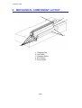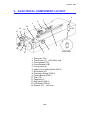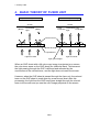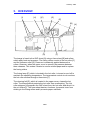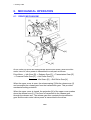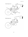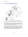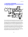
1
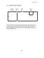
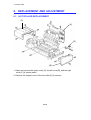
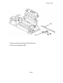
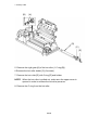
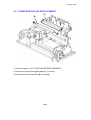
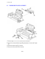
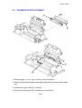
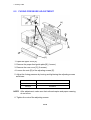
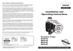
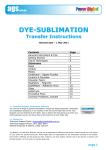
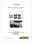
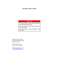
1 January 1990
1. SPECIFICATIONS
Maximum Transparency Size: A4 or 8 1/2" X 11"
Fuser Sheet Size:
Warm Up Time:
Fusing Speed:
Fusing Lamp:
Power Source:
Power Consumption:
Dimensions (W X D X H):
Weight:
A4:
300 X 210 mm (11.9" X 8.3")
284 X 216 mm (11.2" X 8.5")
8 1/2" X 11":
Approximately 60 sec (20oC)
43 sec/sheet (50 Hz)
37 sec/sheet (60 Hz)
Halogen Lamp (950W)
115V/60Hz
220V/50Hz
240V/50Hz
Stand-by 250W
Minimum 50W
Maximum 1kW
490 X 205 X 125 mm
19.3 X 8.1 X 5.4 inches
8.64 kg (19.1lb)
10-1
1 January 1990
2. MECHANICAL COMPONENT LAYOUT
1
2
3
4
5
1. Cleaning Felt
2. Hot Roller
3. Pressure Roller
4. Exit Rollers
5. Drive Gears
10-2
1 January 1990
3. ELECTRICAL COMPONENT LAYOUT
4
2
3
1
14
12
115V
13
11
4
5
10
6
9
8
7
1. Thermistor (TH)
2. Transformer (T) ...220V/240V only
3. Thermoswitch (TS)
4. Circuit Breaker (CB)
5. Fusing Lamp (L)
6. Upper Cover Safety Switch (SW 2)
7. Drive Motor (M)
8. Distribution Board (PCB 2)
9. Control Board (PCB 1)
10. Triac (TR)
11. Capacitor (C)
12. Main Switch (SW 1)
13. LED Board (PCB 3)
14. Resistor (R) ...115V only
10-3
220V/240V
1 January 1990
4. BASIC THEORY OF FUSER UNIT
Not processed by the fuser
After fuser unit processing
Screen
Screen
Shadow
Shadow
(Black) Transmitted (Black)
Light
Color
Color
Projection Transmitted Projection
Light
Colored Toner
OHP Sheet
Light diffuses
Light from OHP
Light from OHP
Light goes straight
When an OHP sheet with a full-color copy image is projected on a screen,
the color toner areas on the OHP sheet are visible as black. This because
the light passing through the OHP is diffused and refracted by the
unevenness of the colored toner, and the light does not reach the screen.
However, when the OHP sheet is passed through the fuser unit, the colored
toner on the OHP sheet is made even by pressure and heat. After this
processing, the light from the OHP lamp goes straight through the colored
toner to the screen and you see the color image projected on the screen.
10-4
1 January 1990
5. OVERVIEW
[I]
[H]
[[C]
[G]
[E]
[B]
[A]
[D]
[F]
The image is fused to the OHP sheet [A] using a fuser sheet [B] and rollers
which apply heat and pressure. The fusing rollers consist of the hot roller [C]
and the pressure roller [D]. Pressure is constantly applied between the
rollers. However, when the upper cover is opened, the pressure between
them releases. This makes it easier to remove misfed paper and to replace
the fusing rollers.
The fusing lamp [E], which is located in the hot roller, is turned on and off to
maintain the operating temperature. The temperature control circuit monitors
the hot roller surface through a thermistor [F].
The cleaning felt [G], which is located in the upper cover, cleans the hot
roller. The thermoswitch protects the hot roller from overheating. The Hot
roller strippers [H] separate the OHP sheet from the hot roller and direct it to
the exit rollers [I]. The fuser sheet has two functions: it prevents toner from
sticking to the fusing rollers and it prevents paper misfeeds.
10-5
1 January 1990
6. MECHANICAL OPERATION
6.1 DRIVE MECHANISM
[J]
[I]
[K]
[L]
[D]
[C] [B]
[F]
[E]
[D]
[H]
[C]
[G]
[B]
[A]
An ac motor [A] drives the fusing rollers and the exit rollers. when the drive
motor turns on, drive power is transmitted to each part as follows:
Drive Motor → Idle Gear [B] → Release Gear [C] → Transmission Gear [D]
→ Pressure Roller Gear [E] → Hot Roller Gear [F]
Idle Gears [G] → Exit Roller Gear [H]
When the upper cover is open, the release spring [I] lifts the release arm [J]
and uncouples the release gear from the transmission gear. This provides
mechanical safety protection.
When the upper cover is closed, the projection [K] of the upper cover pushes
down the release lever [L]. This force is transmitted to the release gear
through the release arm. The release gear then contacts the transmission
gear and the main motor’s drive power is transmitted to the rollers.
10-6
1 January 1990
[K]
Close the upper cover
[L]
[C]
[J]
[A]
[B]
[D]
Open the upper cover
10-7
1 January 1990
6.2 PRESSURE RELEASE MECHANISM
[A]
[B]
[D]
[E]
[F]
[C]
Open the upper cover
Close the upper cover
To make it easier to remove misfed paper and to replace the fusing rollers,
the fusing pressure is released when the upper cover is opened.
When the upper cover is opened, the pivot [A] of the upper cover moves to
the rear side, and the pressure roller brackets [B] are pushed down. The
pressure roller [C], which is mounted on the pressure roller brackets, also
moves down and separates from the hot roller [D].
When the upper cover is closed, the pivot of the upper cover moves to the
front side. and the pressure roller brackets are raised by the force of the
pressure springs [E]. The pressure roller moves up and contacts the hot
roller. This fusing pressure can be adjusted by tightening and loosening the
screws [F] mounted on the pressure springs (One on each end).
10-8
1 January 1990
7. ELECTRICAL OPERATION
7.1 FUSING LAMP CONTROL
Transformer
Circuit
Breaker
Cover
SW
220V/240V
Main
SW
115V
A
Distribution
Board
B
Thermoswitch
Fusing
Lamp
Lamp
Trigger
Circuit
DC Power
Supply
Circuit
Zero
Cross
Circuit
C
DC +15V
Triac
Control
Board
Thermistor
Temperature
Control
Circuit
Display
Circuit
LED Board
The ac power from the outlet [A] goes directly to the fusing lamp. The fusing
lamp is controlled by the triac, the distribution board, and the control board.
The dc power supply circuit on the distribution board steps down the wall
outlet voltage to +15 volts. (In the 220V/240V version, the ac power from the
outlet is stepped down to 100 volts ac by an outer transformer and then goes
to the dc power supply circuit.) +15 volts dc is supplied to all dc circuits.
The zero cross circuit on the distribution board produces and sends a zero
cross signal [B] to the lamp trigger circuit. The temperature control circuit on
the control board detects the fusing temperature by monitoring the resistance
of the thermistor, and sends the control signal to the lamp trigger circuit.
The lamp trigger circuit sends the fusing lamp trigger signal [C], which has
the same timing as the zero cross signal, to the triac to turn on the triac. The
fusing lamp then receives full power [D] from the wall outlet.
10-9
1 January 1990
Based on the value of the thermistor’s resistance, the triac turns on and off to
keep the hot roller’s temperature in the operation range (155oC ± 5oC).
The lamp trigger circuit sends the trigger signal until the temperature reaches
the operating level. At the same time, the control signal goes from the
temperature control circuit to the display circuit. The display circuit controls
the LED display. During stand-by, the LED blinks to display the waiting time.
When the temperature reaches to the operating level, the LED is lit to show
that the fuser is ready to use.
10-10
1 January 1990
7.2 DRIVE MOTOR CONTROL
Circuit
Breaker
Cover
SW
Main
SW
Drive
Motor
M
Capacitor
The ac power from the wall outlet goes directly to the motor. When the main
switch is turned on, the motor starts rotating. However, when the upper cover
is opened, the drIve motor stops rotating. For safety purposes, the drive
motor is stopped both electrically (by the cover switch) and mechanically (see
"DRIVE MECHANISM").
10-11
1 January 1990
8. REPLACEMENT AND ADJUSTMENT
8.1 HOT ROLLER REPLACEMENT
[C]
[A]
[D]
[B]
1. Open and remove the upper cover [A], the left cover [B], and the right
cover [C] (4 screws each).
2. Remove the support cover of the hot roller [D] (2 screws).
10-12
1 January 1990
[B]
[A]
3. Remove the left lamp terminal [A] (2 screws).
4. Pull out the fusing lamp [B].
10-13
1 January 1990
[B]
[A]
[D]
[C]
[E]
5. Remove the right gear [A] of the hot roller (1 C-ring [B]).
6.Remove the hot roller holder [C] (2 screws).
7. Remove the hot roller [D] with C-ring [E] and holder.
NOTE: When the hot roller is pulled out, make sure the upper cover is
opened in order to release the hot roller pressure.
8. Remove the C-ring from the hot roller.
10-14
1 January 1990
8.2 PRESSURE ROLLER REPLACEMENT
[A]
[B]
1. Perform steps 1 to 9 of "HOT ROLLER REPLACEMENT".
2. Remove the paper feed guide plate [A] (1 screw).
3. Remove the pressure roller [B] (2 bushing).
10-15
1 January 1990
8.3 THERMOSWITCH REPLACEMENT
[B]
[A]
[C]
[D]
1. Perform steps 1 to 9 of "HOT ROLLER REPLACEMENT".
2. Remove the entrance [A] and upper [B] guide plates (2 screws and 2 spacers).
3. Remove the upper stay [C] (2 screws).
4. Remove the thermoswitch [D] (2 screws).
10-16
1 January 1990
8.4 THERMISTOR REPLACEMENT
[B]
[A]
[C]
[D]
1. Perform steps 1 to 9 of "HOT ROLLER REPLACEMENT".
2. Remove the entrance [A] and upper [B] guide plates (2 screws and 2 spacers).
3. Remove the upper stay [C] (2 screws).
4. Remove the thermistor [D] (3 clamps and 1 connector).
10-17
1 January 1990
8.5 FUSING PRESSURE ADJUSTMENT
[D]
[A]
[E]
[B]
[C]
1. Open the upper cover [A].
2. Remove the paper feed guide plate [B] (1 screw).
3. Remove the rear cover [C] (2 screws).
4. Loosen the nuts [D] of the adjusting screws [E].
5. Adjust the fusing pressure by loosing and tightening the adjusting screws
as follows:
FUSING PRESSURE
DIRECTION OF THE ADJUSTING SCREW
Weaker
Counterclockwise
Stronger
Clockwise
NOTE: After adjustment, make sure that unfused copies and paper creasing
do not occur.
6. Tighten the nuts of the adjusting screws.
10-18