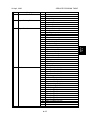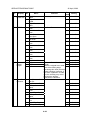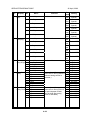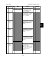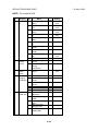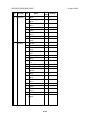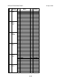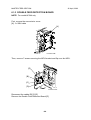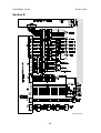
1
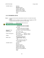
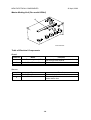
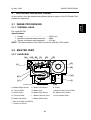
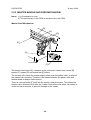
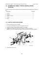
SERVICE MANUAL
(Machine code: C244/C239)
TABLE OF CONTENTS
1. OVERALL INFORMATION ......................................................... 1-1
1.1 ESSENTIAL DIFFERENCES BETWEEN C244/C239 AND
C235 MODELS..........................................................................................1-1
1.2 SPECIFICATIONS...............................................................................1-1
1.2.1 FOR MODEL #C244.........................................................................1-1
1.2.2 FOR MODEL #C239.........................................................................1-2
1.3 NEW ELECTRICAL COMPONENTS ........................................................1-3
1.3.1 FOR MODEL #C244.........................................................................1-3
Printed Circuit Board Layout (For model #C244) ..................................1-3
Paper Feed Section (For model #C244) ...............................................1-3
Master Making Unit (For model #C244) ................................................1-4
Table of Electrical Components ............................................................1-4
1.3.2 FOR MODEL #C239.........................................................................1-5
Printed Circuit Board Layout (For model #C239) ..................................1-5
Master Making Unit (For model #C239) ................................................1-5
Table of Electrical Components ............................................................1-6
Others ...................................................................................................1-6
2. DETAILED DESCRIPTIONS ....................................................... 2-1
2.1 IMAGE PROCESSING ..............................................................................2-1
2.1.1 THERMAL HEAD..............................................................................2-1
Specifications........................................................................................2-1
2.2 MASTER FEED .........................................................................................2-1
2.2.1 OVERVIEW ......................................................................................2-1
2.2.2 MODIFICATIONS FOR JAM REMOVAL ..........................................2-2
Master Duct Sensor Mechanism...........................................................2-2
Pull-out distance ...................................................................................2-3
Master Shutter Mechanism ...................................................................2-4
2.3 PAPER FEED............................................................................................2-5
2.3.1 DOUBLE FEED DETECTION MECHANISM....................................2-5
2.3.2 MASTER MAKING AND FEED MECHANISM..................................2-6
Master Feed Mechanism ......................................................................2-6
2.4 DRUM........................................................................................................2-7
Drum Idling Mechanism ........................................................................2-7
3. INSTALLATION .......................................................................... 3-1
3.1 EDITING FUNCTION TYPE 85 INSTALLATION (OPTION)......................3-1
3.1.1 ACCESSORY CHECK LIST .............................................................3-1
3.1.2 INSTALLATION PROCEDURE ........................................................3-1
3.2 INTERFACE CABLE TYPE 85 INSTALLATION (OPTION)......................3-2
3.2.1 INSTALLATION PROCEDURE ........................................................3-2
i
4. SERVICE TABLES...................................................................... 4-1
4.1 SERVICE PROGRAM TABLE ...................................................................4-2
1. Data Logging ......................................................................................4-2
2. Basic Settings.....................................................................................4-7
3. System Settings................................................................................4-11
4. Input Test Mode................................................................................4-12
5. Output Test Mode.............................................................................4-15
6. System Adjustment...........................................................................4-19
7. Memory Data Clear ..........................................................................4-36
8. System Test......................................................................................4-37
9. Printer Controller ..............................................................................4-38
4.1.1 CLEARING THE FACTORY SETTINGS (SP7-1)...........................4-39
4.1.2 LOAD PROGRAM (SP8-2) .............................................................4-40
5. PREVENTIVE MAINTENANCE................................................... 5-1
5.1 MAINTENANCE TABLE ............................................................................5-1
6. REPLACEMENT AND ADJUSTMENT........................................ 6-1
6.1 MASTER FEED SECTION ........................................................................6-1
6.1.1 MASTER MAKING UNIT REMOVAL................................................6-1
6.1.2 MASTER FEED CLUTCH REMOVAL ..............................................6-1
6.1.3 DOUBLE FEED DETECTION BOARD .............................................6-4
6.1.4 DOUBLE FEED SENSOR ADJUSTMENT .......................................6-5
6.1.5 DRUM POSITION ADJUSTMENT....................................................6-6
7. POINT TO POINT DIAGRAM ...................................................... 7-1
7.1 FOR MODEL #C244.................................................................................7-1
7.2 FOR MODEL #C239...............................................................................7-11
ii
ESSENTIAL DIFFERENCES BETWEEN C244/C239 AND C235 MODELS
1. OVERALL INFORMATION
1.1 ESSENTIAL DIFFERENCES BETWEEN C244/C239
AND C235 MODELS
No.
1
2
Item
Main Processing Unit
(MPU)
Double feed detection
sensor, Double feed
detection board
Memory Board
3
Master duct sensor
4
5
6
7
New SP modes
Ink and master
Thermal Head
8
Master Feed Control
Motor
9
10
11
Anti-Static Roller
Quality Blade
Side Fence Lock Lever
Remarks
Main Processing Unit (MPU) is unique to each
model.
Detects when the paper double feeds. Refer to
the detailed section descriptions.
Not used in the C239.
The C244 and C239 models do not include the
memory board as standard equipment (option
only).
Detects when a master remains in the master
buffer duct. Refer to the detailed section
descriptions.
Some SP modes were changed. Refer to the
service tables section for details.
Supplies for 400 dpi are used in the C239
model.
A 400 dpi thermal head is used in the C239
model.
Not used in the C239.
There is a clutch in the master making unit
instead of the master feed motor.
Not used in the C239.
Not used in the C239.
Not used in the C239.
1.2 SPECIFICATIONS
1.2.1 FOR MODEL #C244
NOTE: The specifications are identical to the C235 model, expect for the power
source, power consumption and available options.
Power Source:
Power Consumption:
120 V, 60 Hz: 2.4A
220 - 240 V, 50/60 Hz 1.4A
120 V version:
Maximum: 240 W
220 - 240 V version: Maximum: 230 W
1-1
Overall
Information
26 April, 2002
SPECIFICATIONS
Available Options:
26 April, 2002
A3 Drum
A4 Drum
Document Feeder
Exposure Glass Cover
Interface Cable Type85
Editing Function Type85
Printer Unit Type 80RCP80
Sorter
TC-II
1.2.2 FOR MODEL #C239
NOTE: 1) Only the items that are differences from the C235 model are shown
below.
2) Master and ink are different from the C235 model. Supplies for C233
model are not commonly used in the C239 model.
Master Processing:
Scanning (Pixel Density):
Master Process Time:
Master Eject Box
Capacity:
Power Source:
Power Consumption:
Weight:
Master Type:
Available Options:
Digital with 400 dpi thermal head
400 dpi CCD
Platen mode:
Less than 16 seconds (A3 paper)
Less than 12 seconds (A4 paper)
ADF mode:
Less than 20 seconds (A3 paper)
Less than 17 seconds (A4 paper)
60 masters / A3 size (Normal conditions)
120 V, 60 Hz: 3.2A
220 - 240 V, 50/60 Hz 1.7 A
120 V version:
Maximum: 340 W
220 - 240 V version: Maximum: 320 W
97 kg [213.9 lb]
104 kg [229.3 lb] with ADF
Thermal master roll type:
320 mm width, 110 m/roll
Yield:
200 masters/roll (at A3 size)
Max run length per master:
2,000 prints
A3 Drum
A4 Drum
Document Feeder
Exposure Glass Cover
Interface Cable Type85
Editing Function Type85
Printer Unit Type 80RCP80
Sorter
TC-II
1-2
26 April, 2002
1.3 NEW ELECTRICAL COMPONENTS
1.3.1 FOR MODEL #C244
Printed Circuit Board Layout (For model #C244)
1
2
C244V103.WMF
Paper Feed Section (For model #C244)
3
C244V001.WMF
1-3
Overall
Information
NEW ELECTRICAL COMPONENTS
NEW ELECTRICAL COMPONENTS
26 April, 2002
Master Making Unit (For model #C244)
4
C244V000.WMF
Table of Electrical Components
Boards
Index No.
1
2
Name
Main Processing Unit (MPU)
Double Feed Detector Board
Function
Controls all machine functions both directly
and through other boards.
Controls the double feed sensor
Sensors
Index No.
Name
3
Double Feed Sensor
Master Duct Sensor
4
Function
Detects the paper double feeds
Detects when a master remains in the
master buffer duct
1-4
26 April, 2002
NEW ELECTRICAL COMPONENTS
Overall
Information
1.3.2 FOR MODEL #C239
Printed Circuit Board Layout (For model #C239)
5
C239V501.WMF
Master Making Unit (For model #C239)
7
6
C239V001.WMF
1-5
NEW ELECTRICAL COMPONENTS
26 April, 2002
Table of Electrical Components
Boards
Index No.
5
Name
Main Processing Unit (MPU)
Function
Controls all machine functions both directly
and through other boards.
Name
Master Duct Sensor
Function
Detects when a master remains in the
master buffer duct
Name
Master Feed Clutch
Function
Controls the master feed control roller
operation to feed the master
Sensors
Index No.
6
Others
Index No.
7
1-6
26 April, 2002
IMAGE PROCESSING
2. DETAILED DESCRIPTIONS
In this section, only the detailed descriptions that are unique to the C239 and C244
models are explained.
Detailed
Descriptions
2.1 IMAGE PROCESSING
2.1.1 THERMAL HEAD
For model #C239
Specifications
• Length .................................................. 292.6 mm
• Number of thermal head elements ....... 4608
• Density of thermal head elements........ 400 dpi
NOTE: The thermal head of the C244 is common with the C235 model.
2.2 MASTER FEED
2.2.1 OVERVIEW
[A]
**[N] [B]
[C]
[D]
[E]
[F]
[L]
[G]
[H]
[K]
[I]
[J]
*[M]
C244D003.WMF
A: Master Edge Sensor
F: Master Set Sensor
K: Cutter
B: Tension Roller
G: Master Roll
L: Master Feed Control Roller
C: Platen Roller
H: Master End Sensor
*M: Master Duct Sensor
D: Thermal Head
I: Master Vacuum Fans
**N: Anti-Static Roller
E: Master Set Roller
J: Master Buffer Duct
*: New for #C244 and #C239
**: Unique to #C244
2-1
MASTER FEED
26 April, 2002
2.2.2 MODIFICATIONS FOR JAM REMOVAL
Master Duct Sensor Mechanism
C244D500.WMF
The master duct sensor detects when a master remains inside the master duct,
and the machine prevents a master jam when printing starts by displaying a
warning.
2-2
26 April, 2002
MASTER FEED
Detailed
Descriptions
Pull-out distance
C244D501.WMF
Compared with the predecessor models (#C229, #C232, #C233, #C235), the pull
out distance of the master making unit was increased from 200 mm to 240 mm.
This is to provide for easier removal of jammed master at the master feed control
roller and in the duct area.
2-3
MASTER FEED
26 April, 2002
Master Shutter Mechanism
[B]
[A]
[B]
[A]
C244D000.WMF
The master shutter [A] was added to prevent the master from being set in the
wrong position. When the master set roller [B] lifts, the master shutter [A] ensures
that the master is in the correct position.
2-4
26 April, 2002
PAPER FEED
2.3 PAPER FEED
2.3.1 DOUBLE FEED DETECTION MECHANISM
Detailed
Descriptions
NOTE: For model #C244 only
[A]
C244D503.WMF
The double feed sensor [A] detects double feeds by measuring the brightness of
light passing through the paper. The machine compares the brightness detected
while the current sheet of paper is being fed with the brightness detected while the
previous sheet was fed.
The sensor takes the first sheet of the job as the standard, to account for the
different thicknesses and colors of paper that various users may use. However, this
means that a double feed will not be detected for the first sheet of paper, and it
also means that if the user changes paper type in mid-job, a double feed could be
detected.
If the machine detects a double feed, it generates an alarm, feeds out all paper
currently in the feed path, and stops printing.
This feature can be switched on by the user if required (User tool 4-28: Double
Feed Warning). SP 3-2-10 also does this.
2-5
PAPER FEED
26 April, 2002
2.3.2 MASTER MAKING AND FEED MECHANISM
NOTE: 1) For model#C239 only.
2) This mechanism in the C239 is the same as in the C233.
Master Feed Mechanism
[B]
[C]
[D]
[E]
[A]
C239D203.WMF
[F]
The master feed motor [A], a stepper motor, drives the master feed control [B],
tension [C], platen [D] and master set [E] rollers.
The tension roller feeds the master slightly faster than the platen roller, to prevent
the master from creasing. Therefore, the master between the platen roller and
thermal head is always under tension.
There is a torque limiter [F] built into the tension roller drive gear. This allows the
tension roller to become free from the master feed motor drive when the master is
under excessive tension, to prevent damage to the master.
2-6
26 April, 2002
DRUM
2.4 DRUM
NOTE: 1) For model #C239 only (the drum for C244 is the same as for C235)
2) This mechanism in the C239 is the same as in the C229 and C233.
Detailed
Descriptions
Drum Idling Mechanism
[B]
Rear
[C]
[D]
[F]
[E]
[A]
Front
C239D213.WMF
Quality Start Mode
In Quality Start mode; the machine enters the drum idling mode before printing.
This ensures that the first print has sufficient ink density even if the machine was
not used for a long time.
The user selects Quality Start mode by pressing a key on the operation panel. The
number of idling rotations is fixed at 45. However, user tool 4-12 can change this
number.
NOTE: In Quality Start mode; the drum idling motion starts, before printing, when
the Start key is pressed. However, if there is no master on the drum, drum
idling is not performed.
Even if the Quality Start mode is active, and there is no master on the
drum, drum idling is skipped although the LED on the operation panel turns
on. When printing for the next original starts, the machine enters drum
idling mode if a large enough master is wrapped around the drum (it will
not be done for an A4 master on an A3 drum).
The drum idling roller [A] puts the ink onto the screens and master before printing.
The idling roller motor [B] turns to press the drum idling roller against the inner
surface of the drum screen [C]. The spring tension supplies additional force for this.
2-7
DRUM
26 April, 2002
The cam [D] is turned by the motor, moving the drum idling roller towards the drum
screen. The actuator disk [E] interrupts the idling roller HP sensor [F] when the
drum idling roller is being used.
Auto Quality Start Mode
Auto Quality Start is done if the user does not select Quality Start mode. (It can be
disabled with a user tool.)
In Auto Quality Start mode, the idling
motion depends on how long the
machine was not in use and on the
temperature detected by the
thermistor [A] in the drum.
The CPU detects a low temperature
condition if the thermistor [A] reports
approximately 15 °C or lower. If the
detected temperature is 28 °C or
higher, it is a high temperature
condition.
[A]
The number of drum idling rotations
depends on temperature and period of
machine inactivity, as shown in the
C239D111.WMF
following table.
NOTE: User Tool 4-14 can be used to change the number of rotations for each of
these conditions.
Period/
Temperature
High
(28 °C or higher)
Normal
(15 to 28 °C)
Low
(15 °C or lower)
Less than 4
hours
4 to 24 hours
24 to 72 hours
Over 72 hours
0
0
0
15
0
0
15
15
0
15
45
45
NOTE: The drum rotation speed during idling is fixed at 90 rpm.
2-8
26 April, 2002
DRUM
Drum Rotation Speed during Idling
The drum rotation speed varies during this mode as shown in the table below. In all
cases, the drum idling roller returns to home position when drum rotation speed
reaches 75 rpm.
- Change of drum rotation speed (rpm) with temperature Temperature
Trial
Print
1st Print
2nd
Print
75
Idling
Roller
Returned
3rd Print 4th Print 5th Print 6th Print
High
(above 28 °C)
60
16
Idling
Idling
Roller On Roller On
Normal
(15 °C ~ 28°C)
16
30
60
Idling
Idling
Idling
Roller On Roller On Roller On
Low
(below 15 °C)
16
16
30
60
Idling
Idling
Idling
Idling
Roller On Roller On Roller On Roller On
90
105
120
120
75
Idling
Roller
Returned
90
105
120
75
Idling
Roller
Returned
90
105
NOTE: These figures apply to the highest printing speed (speed 5, which is at 120
rpm).
2-9
Detailed
Descriptions
Whether the machine is in Quality Start mode or not, the drum idling roller is
always used for the trial print (the print to complete the master making), and for the
first and second prints. If a low temperature condition is detected, the drum idling
roller is also used for the third print.
26 April, 2002
EDITING FUNCTION TYPE 85 INSTALLATION (OPTION)
3. INSTALLATION
There are no differences from the C235 model in this section, except that the
Editing Function Type 85, the Interface Cable Type 85 installation procedures were
added.
3.1.1 ACCESSORY CHECK LIST
Check the quantity and condition of the accessories in the box against the following
list:
Description
Quantity
1. Stepped Screw............................................................................... 2
3.1.2 INSTALLATION PROCEDURE
[A]
C244I500.WMF
1. Remove the rear cover (6 screws).
2. Connect the Editing Function board [A] to CN106 on the MPU (2 screws).
3-1
Installation
3.1 EDITING FUNCTION TYPE 85 INSTALLATION
(OPTION)
INTERFACE CABLE TYPE 85 INSTALLATION (OPTION)
26 April, 2002
3.2 INTERFACE CABLE TYPE 85 INSTALLATION
(OPTION)
Check the quantity and condition of the accessories in the box against the following
list:
Description
Quantity
1. Screw ............................................................................................. 2
2. Spacer ........................................................................................... 2
3. Video I/F board .............................................................................. 1
4. Cable ............................................................................................. 1
5. Bind................................................................................................ 1
3.2.1 INSTALLATION PROCEDURE
1. Remove the rear cover (6 screws).
2. Cut away the blindfold cover [A] on the right rear cover.
3. Install the Video I/F board [B] to the MPU. (2 screws)
4. Connect the cable [C] to the video I/F board. (2 screws, 2 spacer)
NOTE: You need to adjust the length of harness using the bind [D] enclosed.
[B]
[A]
[D]
[C]
C244I520.WMF
5. Reinstall the rear cover
3-2
26 April, 2002
SERVICE PROGRAM TABLE
4. SERVICE TABLES
Some SP modes were checked or newly added for the C244 and C239 models.
The following table shows all of the items in the service program mode.
NOTE: The marks beside the SP mode numbers in the following tables represent
the following meanings.
*: A new item was added or the default setting was changed.
**: New item, used for the C239 models but not used for the C244 models.
***: New item, used for the C244 models but not used for the C239 models.
Main Menu Number List
1. Data Logging
2. Basic Settings
3. System Settings
Service
Tables
4. Input Test Mode
5. Output Test Mode
6. System Adjustment
7. Memory Data Clear
8. System Test
9. Printer Controller
4-1
SERVICE PROGRAM TABLE
26 April, 2002
4.1 SERVICE PROGRAM TABLE
1. Data Logging
No.
Display
1-1 Master Counters
No.
Menu
1 Total Master Counter
2 Total Master Counter - ADF
1-2 Master Counters Size
1
2
3
4
5
6
7
1
2
3
4
5
1
2
3
4
5
6
1
2
3
4
5
6
7
8
9
10
11
12
13
14
15
16
17
18
19
20
21
1-3 Master Counter Orig Type
1-4 Master Counter Ppr Type
1-5 Master Counter Copy Mode
A3/DLT
B4/LG
A4-L/LT-L
A4/LT
B5-L
B5
Other Sizes
Letter Mode
Letter/Photo Mode
Photo Mode
Pencil Mode
Tint Mode
Standard Paper
Thick Paper
Thin Paper
Special
User 1
User 2
Economy Mode
Combine 2
Combine 4
Memory Combine
Enlargement Mode
Reduction Mode
Zoom Mode
Directional Magnification
Auto Magnification
Make-up Mode
Make-up Mode-Photo
Margin Erase
Online Mode
Overlay Mode
Format Overlay
Online Overlay
Memory Overlay
Date Stamp
Page Number
Default Stamp
Memory Original
4-2
Function
Total master counter.
Master counter made in
ADF mode.
Master counters for each
original size used.
“-L”: Lengthwise feed
Master counters for each
original type used.
Master counters for each
paper type used.
Master counters for various
copy modes.
SERVICE PROGRAM TABLE
No.
Display
1-5 Master Counter Copy Mode
No.
22
23
24
25
26
27
28
29
30
33
34
35
1-6 Master Counters 1
Sort
2
3
4
5
1-7 Job Counters - Sort 1
2
3
4
5
6
1-8 Print Counters
1-9 Print Counter - Size
Menu
Up/Down Shift
Side Shift
Short Master
Image Rotation
Same-No. Class
By-Class Class
Manual Class
Job Separator
Autocycle
Sort
Class Sort
Online Sort
1-20 copies per Master
21-40 copies per Master
41-50 copies per Master
51-80 copies per Master
81- copies per Master
1-5 masters per Job
6-10 masters per Job
11-20 masters per Job
21-30 masters per Job
31-50 masters per Job
51- masters per Job
1 Total Print Counter
2 Print Counter-Color Drum
1
2
3
4
5
6
7
8
9
10
1-10 Print Counters - Ppr 1
Type
2
3
4
5
6
1-12 Print Counters 1
Sorter
2
3
4
5
Over A3/DLT
A3/DLT
B4/LG
A4-L/LT-L
A4/LT
B5-L
B5
A6-L
Under A6-L
Other Sizes
Standard Paper
Thick Paper
Thin Paper
Special
User 1
User 2
Larger than A4
A4 and Smaller
From Paper Table
From Tray 1 (Feed Station)
From Tray 2 (Feed Station)
4-3
Function
For details, see the sorter
service manual.
Master counters for sorter
mode. For details, see the
sorter service manual.
Job counters for sorter
mode. For details, see the
sorter service manual.
Total print counter.
Print counter made with the
optional color drum.
Print counters for each
paper size used.
“-L”: Lengthwise feed
Print counters for each
paper type used.
Print counters for sorter
mode. For details, see the
sorter service manual.
Service
Tables
26 April, 2002
SERVICE PROGRAM TABLE
No.
Display
1-13 Copies Per Orig
Counters
1-14 Counter/Jam Ratio
1-15 Feed-in/Reg Roller
Jams
1-17 Jam Counters Sorter
26 April, 2002
No.
1
2
3
4
5
6
7
8
9
10
11
12
1
2
3
4
5
6
7
8
9
10
11
12
13
14
*15
1
2
3
4
5
6
7
8
Menu
1 - 3 Prints
4 - 5 Prints
6 - 10 Prints
11 - 20 Prints
21 - 30 Prints
31 - 50 Prints
51 - 70 Prints
71 - 100 Prints
101 - 200 Prints
201 - 500 Prints
501 - 1000 Prints
Over 1000 Prints
Master Set Error
Master Clamp Error
Master Cut Error
Master Eject ON Check
Pressure Plate Error
Master Eject OFF Check
Registration ON Check
Feed Timing ON Check
Feed Timing OFF Check
Paper Upper Wrapping
Paper Lower Wrapping
Paper Exit OFF Check
DF Feed-in Error
DF Feed-out Error
Master Duct OFF Check
Jam P0 Standard
Jam P0 Thick
Jam P0 Thin
Jam P0 Others
Jam P1 Standard
Jam P1 Thick
Jam P1 Thin
Jam P1 Others
9
10
11
12
1
2
3
4
5
Jam P2 Standard
Jam P2 Thick
Jam P2 Thin
Jam P2 Others
Relay Transport section
Horizontal Trans. section
Vertical Trans. section
Lower 20 Bins section
Upper 20 Bins section
4-4
Function
Copies-per-original
counters.
Counters for various types
of jams. Jam ratios are also
displayed.
Feed-in jams and
registration roller jams for
various paper sizes and
paper types.
Registration roller jams
(when the paper feed timing
sensor stays on) for various
paper sizes and paper
types.
Upper wrap, lower wrap,
and feed-out jams for
various paper sizes and
paper types.
Counters for various
location jams in the sorter.
For details, see the sorter
service manual.
No.
Display
1-18 Other Counters
SERVICE PROGRAM TABLE
No.
1
2
3
4
5
6
7
8
9
10
11
14
1-19 Machine Information 1
2
*7
*14
1-20 Service Information
*16
1
2
***1- Double Feed
21 Counters
*1-22 Sales Mode Check
1
2
3
1
2
3
4
5
6
7
8
9
10
Menu
Set Master Counter
Ejected Master Counter
Ink Pump Rotation Count
Master End Counter
Ink End Counter
Master Full Counter
Original Counter ADF
Original Counter Platen
Misfeed Setting Counter
Function
Number of times the user
changed the “Misfeed”
setting for paper feed or
separation pressures.
Number
of times the user
Multifeed Setting Count
changed the “Multifeed”
setting for paper feed or
separation pressures.
Number of times an error
Start Error Message Cnt.
message appeared when
the Start key was pressed.
Open Counter Cover on Move See the sorter service
manual.
ROM Part Number
Serial Number
Use this to view the data
input with SP 3-1-1.
ROM Version
JS Sorter ROM Version
Displayed when the sorter
is installed.
Power On Time
Tel. Number for Service
Enter data with SP3-1-6 at
installation if required.
SC Counter
Displays the latest 20
records of the SC codes
displayed. Use the arrow
keys to view the records.
From Paper Table
From Tray 1
From Tray 2
Save Ink in Sorter Mode
Japan Display Type
Swap Start Key
Ink Supply Pre-Printing
Set Job Separation
Set Key Counter
Set Key Card
Paper Delivery Table
Main Scan Position
Scan Start Position - DF
4-5
Do not use (Japanese
version use only).
Do not use (Japanese
version use only).
Service
Tables
26 April, 2002
SERVICE PROGRAM TABLE
No.
Display
*1-22 Sales Mode Check
No.
11
*12
*13
*14
26 April, 2002
Menu
Scanning Speed
Config data
Controller NVRAM
NIB NVRAM
4-6
Function
Do not use (Japanese
version use only).
26 April, 2002
SERVICE PROGRAM TABLE
2. Basic Settings
Display
2-1 Default
User
Settings
2-2 Disable
Sensors
2-3 JS Sorter
Settings
2-4 Destination
Settings
No.
Menu
1 Print Speed
2 Default Image
Position - Tp/Btm
3 Default Image
Position Lt/Rt
4 Make-up Pattern1
5 Make-up Pattern2
6 Make-up Pattern3
7 Make-up Pattern4
1 Ink Detection
2 Paper Length
Detection
3 Paper Size
Detection
4 Drum Master
Detection
5 Platen Cover Set
Detect
6 ADF Close
Detection
1 Set Unit
Function
See Note 1.
Default
3
0
1
1
1
1
ON
ON
1 to 5
-15.0 to
15.0 mm
-10.0 to
10.0 mm
1 to 40
1 to 40
1 to 40
1 to 40
ON/OFF
ON/OFF
ON
ON/OFF
ON
ON/OFF
ON
ON/OFF
ON
ON/OFF
0
See Note 2.
Enables/disables various
sensors for test purposes.
For details, refer to the sorter U&L U&L/Upper/
service manual.
Lower
No
Yes/No
OFF ON/OFF
2 Sort Number Limit
3 Ink Save Mode for
Sorter
4 1 Bin Capacity Limit
50
5 Interval Jogger Set 0
Sort
6 Interval Jogger Set 0
Class
7 Speed Setting
OFF
1 Set Type by Code By entering the machine
code (e.g. for C244-27, input
244-52), the following values
go to the factory settings for
that model:
* User tool 1-4 (mm/inch)
* User tool 1-5 (language)
* SP 2-4-3
* SP 2-4-4
2 Display Type (for
Japan)
Setting
NOTE
244-52: North America
244-27: Ricoh Europe
* Use the point ( . ) key to
enter “-.”
Do not use.
4-7
0
1 to 50
0 to 1
0 to 1
ON/OFF
-
0 to 2
Service
Tables
No.
SERVICE PROGRAM TABLE
No.
Display
No.
26 April, 2002
Menu
Function
2-4 Destination
Settings
3 Drum Selection
See Note 3.
4 Machine Destination See Note 4.
2-5 T Head
Energy
Settings
1 Thermal Head
Energy
Temperature
Control – Black Ink
2 Thermal Head
Energy
Temperature
Control – Color Ink
3 T Head Energy Standard
4 T Head Energy Economy
1 APS A5 Size
Detection
2 Swap Start Key
3 A3 Master 2 Count
Up
4 Num of Matser Eject
Trial
2-6 Other
Settings
See Note 5.
Default
0
Setting
ON
DLT/A3
0: Other
1: Japan
ON/OFF
ON
ON/OFF
7
0 to 50%
Thermal head energy in
standard and economy
modes, as percentage of full
power.
See Note 6.
13
0 to 43%
No
Yes/No
See Note 7.
See Note 9.
No
2
Yes/No
1 to 3
2
1 to 3
Auto
Auto/OFF
OFF
ON/OFF
0
OFF
0 to 2
ON/OFF
This specifies the number of
master eject attempts before
an error is indicated.
5 Auto Master Save
Select
6 Ink Supply w/Trial
Print
ON: Ink is supplied while a
trial print is made after
making a new master.
7 Ink Auxiliary Supply See Note 11.
8 Drum Idling
See Note 10.
Notes
1: 2-1-1 (Default print speed, cpm)
1: 60, 2: 75, 3: 90, 4: 105, 5: 120
2: 2-1-4 to -7 (Default make-up patterns 1 to 4)
0 to 39: Preset patterns, from 1 to 40
4-8
26 April, 2002
SERVICE PROGRAM TABLE
3: 2-4-3 (Drum Size – A3 or DLT)
This setting changes the master making area. It also affects the available range for
the default image position shift (top/bottom, SP2-1-2).
A3: -15 mm to + 15 mm
DLT: -10 mm to + 10 mm
4: 2-4-4 (Machine Destination)
Always set this mode as “Other.” If “Japan” is selected, User Tools 6-10 that are
not used for other versions is displayed.
5: 2-5-1 and -2 (Thermal head energy control with temperature)
Less than 19 °C
More than 19 °C
Standard
SP 2-5-3 value
(Default: 7%)
(Y+T–19+1)%
(Limit: 22%)
Economy
SP 2-5-4 value
(Default: 20%)
(Y+T–19+1+Z)%
(Limit: 40%)
Y: SP2-5-3 value
T: The ink temperature
Z: SP2-5-4 value
6: 2-6-1 (APS A5 Size Detection)
This determines how the machine behaves if the APS sensors cannot detect the
original because it is too small.
0: No original detected, 1: A5 assumed
Default: 0
7: 2-6-2 (Swap Start Key)
Enables swapping the Start (master making) key function and the Print key function
depending on the end user”s preference. (“No” is the default setting.)
8: 2-6-3 (Sharpen Image Mode)
When this SP mode is on, fine details become more apparent in letter mode. But
the edges of paper pasted onto the original might appear on the print.
9: 2-6-4 (Double count-up for A3 masters)
0: The counters go up by 1 only.
1: The master counter goes up by 2.
2: The master and print counters both go up by 2.
4-9
Service
Tables
If this is switched on, the energy supplied to the thermal head will depend on the
temperature measured by the thermistor in the drum.
SERVICE PROGRAM TABLE
26 April, 2002
10: 2-6-8 (Drum Idling)
This mode has two options: “Fast” and “Slow”. Slow is the default setting.
Fast mode (High, Normal) skips the 30, 60, 75-rpm drum rotation speed at the
beginning of printing. Consequently, the drum rotation speed increases as shown
in the table below. Slow mode (Normal, Low) does not skip the 30, 60, 75-rpm
drum rotation speed. Note that there are two cases depending on the temperature
inside of the drum, detected by the thermistor.
SP2-6-8
Setting
Slow
Fast
Drum
Temperature
High
15 °C or above
Normal
15 °C ~ 28°C
Low
Below 15 °C
High
15 °C or above
Normal
15 °C ~ 28°C
Low
Below 15 °C
Trial
Print
1st
Print
2nd
Print
3rd
Print
4th
Print
5th
Print
6th
Print
16
60
75
90
105
120
120
16
30
60
75
90
105
120
16
16
30
60
75
90
105
16
90
105
120
120
120
120
16
90
105
120
120
120
120
16
16
30
60
75
90
105
* These figures apply to the highest printing speed (120-rpm).
11: 2-6-7 (Ink Auxiliary Supply)
This mode determines when ink is detected and supplied. There are three possible
settings.
• “0: After”: Ink detection and supply are done when a print job finishes.
• “1: Before”: They are done when the Print Start key is pressed (and before
starting printing).
• “2: No”: Ink is not added except during normal printing.
Note that if the machine detects a low ink condition during printing, ink is supplied
regardless of this setting.
To minimize the wait time for drum idling, ink supply prior to starting printing has
been eliminated by setting this mode to “0: After” as the default. With older
firmware, when the Print Start key is pressed, the machine carries out the ink
detection and (if low ink is detected) starts to supply ink before starting printing.
(This ink detection is likely only when an operator cancels the Auto-cycle mode,
which is selected by default. In the Auto-cycle mode, the machine enters the
printing process without detecting the ink after making a master.)
4-10
26 April, 2002
SERVICE PROGRAM TABLE
3. System Settings
No.
1
*6
*7
*8
*9
3-2 Unit Settings
1
2
3
4
5
6
***
10
Menu
Serial Number
Tel. Number for Service
Date
Installation Date
First Power On Date
Function
Default
Use these to input the
serial numbers, etc.
Do these at installation if
required. The data is
used in the data printout
mode in the system test.
(SP3-1-1 can be seen in
SP1-19. SP3-1-6 can be
seen in SP1-20-1.)
Set Job Separation
Yes
Set Key Counter
Set to Yes if installed.
No
Set Key Card
Japan only
No
Set Paper Delivery Table Japan only
No
Set Paper Feed Station Japan only
No
Set Sorter
Set to Yes if installed.
No
Double Feed Sensor
In Japan, this sensor is
Yes
an option
Setting
No/Yes
No/Yes
No/Yes
No/Yes
No/Yes
No/Yes
No/Yes
Service
Tables
No.
Display
3-1 Installation
Settings
4-11
SERVICE PROGRAM TABLE
26 April, 2002
4. Input Test Mode
SP No.
Display
4-1 Scanner Unit
4-10
Master Making Unit
4-20
Master Eject Unit
4-30
Paper Feed Table
4-31
Paper Feed Table-Paper
4-40
Paper Feed Pressure
4-41
Separation Pressure
4-42
Friction Pad
No.
1
2
3
4
5
6
7
8
1
2
3
4
5
6
7
1
2
3
4
1
2
3
4
1
2
3
4
5
6
7
8
1
2
3
4
1
2
3
4
1
2
3
4
Menu
Scanner HP Sensor
Original Length SN 0
Original Length SN 1
Original Width SN 2
Original Width SN 3
Original Length SN 4
Original Length SN 5
Platen Cover Sensor
Master Unit Set Sensor
Cutter HP Sensor
Master Set Sensor
Master End Sensor
Master Edge Sensor
Platen Release Sensor
Thermal Head Temperature
Eject Box Set Sensor
Master Eject Sensor
Pressure Plate HP Sensor
Pressure Plate Limit SN
Paper Table Lowering SW
Table Lower Limit Sensor
Paper Table Height SN
Paper Table Set Sensor
Paper End Sensor
Paper Length Sensor
Paper Width Detection 0
Paper Width Detection 1
Paper Width Detection 2
Paper Width Detection 3
Paper Width Detection 4
Paper Width Detection 5
Paper Feed Pressure 0
Paper Feed Pressure 1
Paper Feed Pressure 2
Paper Feed Pressure 3
Separation Pressure 0
Separation Pressure 1
Separation Pressure 2
Separation Pressure 3
1st Friction Pad HP Sensor
2nd Friction Pad HP Sensor
Friction Pad Position - Normal
Friction Pad Position - Special
4-12
SP No.
Display
4-50 Paper Transport
4-60
Around the Drum
4-61
Image/Drum Shift HP SN
4-62
Ink
4-80
Other Sections
4-90
Job Separator Unit
4-100 Document Feeder Unit
SERVICE PROGRAM TABLE
No.
1
2
3
4
5
6
7
8
9
1
2
3
4
5
6
7
8
9
10
11
1
2
1
2
3
4
5
1
2
3
1
2
3
4
1
2
3
4
5
6
7
8
9
10
Menu
Paper Registration SN
Paper Feed Timing Sensor
Paper Feed Start Sensor
Tray Feed Start SN
Lower Wrapping Jam SN
Paper Exit Sensor
P Cylinder Feed Encoder
Wing Upper Position SN
Wing Lower Position SN
1st Drum Position Sensor
2nd Drum Position Sensor
3rd Drum Position Sensor
Drum Type Check 0
Drum Type Check 1
1st Drum Master Sensor
2nd Drum Master Sensor
Clamp Close Position SN
Clamper Open Position SN
A3 Cam Sensor
A4 Cam Sensor
Image Shift HP Sensor
Drum Shift HP Sensor
Ink Pump Sensor
Ink Cartridge Set Sensor
Ink Detection
Drum Idling Roller HP SN
Ink Temperature
Front Door Open Detect
Main Motor Lock Detect
Relay Guide Set Sensor
Slider Upper Limit SN
Job Separator Paper SN
Slider Position Sensor
Slider HP Sensor
Installation Detect
Cover Open Sensor
Registration Sensor
Original Rear Sensor
Original Set Sensor
Original Length SN 1
Original Length SN 2
Original Width SN 1
Original Width SN 2
Position Sensor
4-13
Service
Tables
26 April, 2002
SERVICE PROGRAM TABLE
SP No.
Display
4-110 Paper Delivery Table
4-130 JS Sorter
*4-150 Options
26 April, 2002
No.
1
2
3
4
5
6
7
1
2
3
4
5
6
7
8
9
10
11
12
13
14
15
16
17
18
19
20
21
22
23
24
25
26
27
28
1
2
3
Menu
Delivery Table Paper SN
Side Plate Set Sensor
Side Plate Pulse Sensor
Side Plate HP Sensor
End Plate Set Sensor
End Plate Pulse Sensor
End Plate HP Sensor
Lower Bin SN
Lower Entry SN
Upper Bin SN
Upper Entry SN
Relay Paper SN
Horizontal Paper SN
Delivery Table Position SN
Sort Position SN
Lower Side Jogger HP SN
Upper Side Jogger HP SN
Lower End Jogger HP SN
Upper End Jogger HP SN
Lower Turn Gate Limit SW
Upper Turn Gate Limit SW
Lower Turn Gate Paper SN
Upper Turn Gate Paper SN
Lower Door Safety SW
Upper Door Safety SW
Delivery Table Set SW
Vert. Cover Safety SW
Horiz. Cover Safety SW
Stapler Cover Safety SW
Lower Bins Operation SW
Upper Bins Operation SW
Not used
Not used
Not used
Not used
Key Counter Detection
Key Card Detection
Not used
4-14
26 April, 2002
SERVICE PROGRAM TABLE
SP No.
Display
5-001 Scanner Unit
5-010 Master Making Unit
5-020 Master Eject Unit
5-030 Paper Feed Table
5-040 Paper Pressure Motor
5-041 Separation Pressure Motor
5-042 Friction Pad Motor
No.
1
2
3
4
1
2
3
Menu
Xenon Lamp
Move Scanner - Scan
Move Scanner - Return
Move Scanner to HP
Master Feed Clutch
Platen Release Motor
Master Feed Motor
4
5
6
7
8
9
*10
*11
1
2
3
4
5
1
2
1
2
3
4
5
6
7
8
9
1
2
3
4
5
6
7
8
9
10
1
2
Cutter Motor Forward
Cutter Motor Reverse
Move Cutter to HP
Master Vacuum Fan
Master Duct Entrance Sol
Thermal Head ON
Apply Platen Pressure
Release Platen Pressure
M Eject Motor Forward
M Eject Motor Reverse
Pressure Plate to Limit
Press Plate to Eject Pos
Pressure Plate to HP
Paper Table Motor Up
Paper Table Motor Down
Paper Pressure Motor Up
Paper Press Motor Down
Paper Pressure Min
Paper Pressure 1
Paper Pressure 2
Paper Pressure 3
Paper Pressure 4
Paper Pressure 5
Paper Pressure Max
Motor Up
Motor Down
Eject Position
Separation Pressure Min
Separation Pressure 1
Separation Pressure 2
Separation Pressure 3
Separation Pressure 4
Separation Pressure 5
Separation Pressure Max
Standard
Special
4-15
Service
Tables
5. Output Test Mode
SERVICE PROGRAM TABLE
SP No.
Display
5-050 Paper Feed Motor
5-051 Registration Motor
5-052 Paper Delivery
5-060 Drum Rotation
5-061 Clamper Motor
5-062 Image Shift Motor
5-063 Drum Idling Roller
5-064 Around the Drum
5-070 Counters
5-080 Other Sections - Main Body
5-090 Job Separator Unit
26 April, 2002
No.
1
2
3
4
5
6
7
1
2
3
4
5
6
7
1
2
3
4
1
2
3
4
5
6
1
2
1
2
3
4
1
2
1
2
3
4
5
6
1
2
1
2
1
2
3
4
Menu
Slowest
30 rpm
1st Speed
2nd Speed
3rd Speed
4th Speed
5th Speed
Slowest
30 rpm
1st Speed
2nd Speed
3rd Speed
4th Speed
5th Speed
Wing Guide Motor Up
Wing Guide Motor Down
Air Knife Fan
Transport Vacuum Fan
Slowest
1st Speed
2nd Speed
3rd Speed
4th Speed
5th Speed
Clamper Motor - Open
Clamper Motor - Close
Image Shift Motor - !
Image Shift Motor - "
Drum Shift Motor - #
Drum Shift Motor - $
Drum Idling Roller ON
Idling Roller Return
Ink Pump Motor
Printing Pressure Sol.
Shift Pressure Cam to A3
Shift Pressure Cam to A4
3rd Drum Position LED - GREEN
3rd Drum Position LED - RED
Print Counter Up
Master Counter Up
All Indicators On
PSU Fan Motor
Slider Lift Motor - Up
Slider Lift Motor - Down
Job Separator Motor - Forward
Job Separator Motor - Reverse
4-16
SP No.
Display
5-100 Document Feeder Unit
5-110 Paper Delivery Table
5-120 Paper Feed Station
5-130 JS Sorter
SERVICE PROGRAM TABLE
No.
1
2
3
1
2
3
4
1
2
3
4
5
6
7
8
9
10
11
12
13
14
15
16
17
18
19
20
1
2
3
4
5
6
7
8
9
10
11
12
13
14
15
16
17
18
19
20
Menu
Feed Motor
Feed Clutch
Pick-up Solenoid
Side Plate-Extension
Side Plate-Retraction
End Plate-Retraction
End Plate-Extension
R-Tray1 Lift Motor: Up
R-Tray1 Lift Motor: Down
Tray1 Right Lock Sol.
Tray1 Friction Pad Sol.
Tray1 Connection Sol.
L-Tray1 Lift Motor: Up
L-Tray1 Lift Motor: Down
Tray1 Left Lock Sol.
Back Plate - Right
Back Plate - Left
Tray2 Lift Motor: Up
Tray2 Lift Motor: Down
Tray 2 Lock Sol.
Tray2 Friction Pad Sol.
Tray Feed Motor - Forward
Tray Feed Motor - Reverse
Tray Registration Motor
Tray2 Feed Clutch
Tray Relay Clutch
Tray Exit Clutch
Lower Turn Gate Mtr Upt
Lower Turn Gate Mtr Down
Upper Turn Gate Mtr Up
Upper Turn Gate Mtr Down
Relay Transport Motor
Horizontal Transport Mtr
Lower Vert. Transport Mtr
Upper Vert. Transport Mtr
Relay Switching Mtr To Sort
Relay Switching Mtr To Non
Lower S-Jogger Forward
Lower S-Jogger Reverse
Upper S-Jogger Forward
Upper S-Jogger Reverse
Lower E-Jogger Forward
Lower E-Jogger Reverse
Upper E-Jogger Forward
Upper E-Jogger Reverse
Not used
Not used
4-17
Service
Tables
26 April, 2002
SERVICE PROGRAM TABLE
SP No.
Display
5-130 JS Sorter
*5-150 Options
26 April, 2002
No.
21
22
23
24
25
26
27
28
29
30
31
32
1
2
4
Menu
Relay Trans. Fan Mtr
Horz. Trans. Fan1 Mtr
Horz. Trans. Fan2 Mtr
Lower Vrt Trans. Fan1 Mtr
Lower Vrt Trans. Fan2 Mtr
Upper Vrt Trans. Fan1 Mtr
Upper Vrt Trans. Fan2 Mtr
Wing Guide Solenoid
Delivery Table Lock SOL
Lower Turn Gate SOL
Upper Turn Gate SOL
Sorter Free Run
Count-up Key Counter
Count-up Key Card
Not used
4-18
26 April, 2002
SERVICE PROGRAM TABLE
6. System Adjustment
NOTE: For model #C244
Display
6-1 Scan &
Writing
6-2 Master
Making
Density
6-3 Drum
Master
Clamp
6-4 SN
Voltages/
Thresholds
6-5 Sensor
Board Unit
No.
Menu
Function
1 Main Scan Pos. Platen
2 Main Scan Position
- DF
3 Scan Start Pos. Platen
4 Scan Start Position DF
5 Scanning Speed Platen
6 Scanning Speed DF
7 Master Writing
Speed
8 Master Writing
Length
9 Master Main Scan
Pos
*10 Trail Edge Margin
1 Master Making
Density
*2 Master Making
Density Letter/Photo
1 Drum Master Clamp
Regist
1 Master Eject Sensor
2 Drum Master 1
Sensor
3 Drum Master 2
Sensor
4 Master End Sensor
5 Paper Exit Sensor
6 Master Edge Sensor
1 SBU Auto
Calibration
2 SBU Gain SettingEVEN
3 SBU Gain SettingODD
4 SBU DC Count
Setting-EVEN
5 SBU DC Count
Setting-ODD
Side-to-side registration
adjustment; see Note 1.
Scanning start line
adjustment; see Note 2.
See Note 3.
DeSetting
fault
0
-5.0 to 2.0
mm
0
-5.0 to 5.0
mm
0
-2.0 to 5.0
mm
0
-5.0 to 5.0
mm
0 -5.0 to 5.0%
0
-5.0 to 5.0%
See Note 4.
0
-5.0 to 5.0%
Do not use in the field.
0
-5.0 to 5.0%
0
0
1
-3.0 to 3.0
mm
0 to 2mm
0 to 2
2
0 to 2
0
-10 to 10
mm
Adjust the trail edge margin
See Note 5.
See Note 6.
The use of these SP modes
is explained in various parts
of the Replacement and
Adjustment section.
Refer to the Replacements
and Adjustments section.
Do not adjust.
4-19
2.5 1.5 to 3.0 V
2.5 1.5 to 3.0 V
2.5 1.5 to 3.0 V
0.8 0.1 to 3.0 V
2.0 1.5 to 3.0 V
2.0 1.5 to 3.0 V
-
0 to 255
-
0 to 255
-
0 to 255
-
0 to 255
Service
Tables
No.
SERVICE PROGRAM TABLE
No.
Display
No.
26 April, 2002
Menu
Function
6-5 Sensor
Board Unit
6 SBU Reference
Value
7 SBU Offset ValueEVEN
8 SBU Offset ValueODD
6-6 MTF Filters 1 Letter Mode-Main
Scan
2 Letter Mode-Sub
Scan
3 LetterPhoto ModeMain Scan
4 Letter/Photo ModeSub Scan
5 Photo Mode-Main
Scan
6 Photo Mode-Sub
Scan
7 Pencil Mode-Main
Scan
8 Pencil Mode-Sub
Scan
9 Tint Mode-Main
Scan
10 Tint Mode-Sub Scan
*6-7 Drum
1 A3 Drum
Master
2 DLT Drum
Length
3 A4 Drum
6-9 Paper Feed 1 FeedPressure Std
Pressure
Nor Ppr
2 Freq - Normal Paper
3 V Freq - Normal
Paper
4 FeedPressure Std
Thick
5 Freq - Thick Paper
6 V Freq - Thick
Paper
7 Feed Pressure Std
Thin
8 Freq - Thin Paper
9 V Freq - Thin Paper
Do not adjust.
See Note 7.
Adjust the Drum Master
Length
When the original has a solid
area at the trailing edge,
increasing this value prevents
master crinkling. However, if
the drum is placed in a C593
unit, the crinkling may occur
because the printing
mechanism is different.
See Note 8.
4-20
Default
-
0 to 255
-
0 to 255
-
0 to 255
2
0 to 7
1
0 to 7
0
0 to 7
0
0 to 7
4
0 to 7
4
0 to 7
2
0 to 7
1
0 to 7
4
0 to 7
4
0
0
0
0 to 7
0 to 5
0 to 5
0 to 5
3
0 to 6
5
6
0 to 6
0 to 6
3
0 to 6
5
6
0 to 6
0 to 6
1
0 to 6
3
5
0 to 6
0 to 6
Setting
No.
Display
SERVICE PROGRAM TABLE
No.
Menu
Function
6-9 Paper Feed 10 FeedPressure Std See Note 8.
Pressure
Special
11 Freq - Special
Paper
12 V Freq - Special
Paper
13 Feed Pressure Std
User 1
14 Freq - User 1 Paper
15 V Freq - User 1
Paper
16 Feed Pressure Std
User 2
17 Freq - User 2 Paper
18 V Freq - User 2
Paper
See Note 8.
6-10 Separation 1 SepPressure Std
Pressure
Nor Ppr
2 Freq - Normal Paper
3 V Freq - Normal
Paper
4 SepPressure Std
Thick
5 Freq - Thick Paper
6 V Freq - Thick
Paper
7 Sep Pressure Std
Thin
8 Freq - Thin Paper
9 V Freq - Thin Paper
10 SepPressure Std
Special
*11 Freq - Special
Paper
*12 V Freq - Special
Paper
13 SepPressure Std
User 1
14 Freq - User 1 Paper
15 V Freq - User 1
Paper
16 SepPressure Std
User 2
17 Freq - User 2 Paper
18 V Freq - User 2
See Note 8.
Paper
4-21
Default
1
Setting
0 to 6
3
0 to 6
5
0 to 6
5
0 to 6
6
6
0 to 6
0 to 6
5
0 to 6
6
6
0 to 6
0 to 6
4
0 to 6
5
6
0 to 6
0 to 6
2
0 to 6
4
6
0 to 6
0 to 6
4
0 to 6
5
6
1
0 to 6
0 to 6
0 to 6
2
0 to 6
3
0 to 6
2
0 to 6
4
6
0 to 6
0 to 6
2
0 to 6
4
6
0 to 6
0 to 6
Service
Tables
26 April, 2002
SERVICE PROGRAM TABLE
No.
Display
6-11 Friction
Pad
No.
26 April, 2002
Menu
1 Normal Paper
2 Thick Paper
3 Thin Paper
4 Special Paper
5 User1 Paper
6 User2 Paper
6-12 Paper
Clamping
1 Normal Paper
2 Thick Paper
3 Thin Paper
4 Special Paper
5 User1 Paper
6 User2 Paper
6-13 Delivery
Wing Angle
1
2
3
4
5
*6
6-14 Paper Feed 1
Delay
2
3
4
5
6
7
8
6-15 Paper Feed 1
Delay-Thick 2
3
4
5
6
Normal Paper
Thick Paper
Thin Paper
Special Paper
User1 Paper
User2 Paper
16 rpm
20 rpm
30 rpm
60 rpm
75 rpm
90 rpm
105 rpm
120 rpm
16 rpm
20 rpm
30 rpm
60 rpm
75 rpm
90 rpm
Default
NorSee Note 9.
mal
Special
Special
Special
Normal
Normal
EnaSee Note 10.
ble
Enable
Enable
Enable
Enable
Enable
See Note 11.
High
Low
High
Low
High
High
Do not adjust. (Changes the 199
feed motor on timing after the 200
feed start timing sensor is
200
activated.)
219
147
100
53
26
Do not adjust. (Changes the 199
feed motor on timing in thick 200
and special paper modes
200
after the feed start timing
219
sensor is activated.)
147
100
Function
4-22
Setting
Normal/
Special
Normal/
Special
Normal/
Special
Normal/
Special
Normal/
Special
Normal/
Special
Enable/OFF
Enable/OFF
Enable/OFF
Enable/OFF
Enable/OFF
Enable/OFF
High/Low
High/Low
High/Low
High/Low
High/Low
High/Low
0 to 255
0 to 255
0 to 255
0 to 255
0 to 255
0 to 255
0 to 255
0 to 255
0 to 255
0 to 255
0 to 255
0 to 255
0 to 255
0 to 255
No.
Display
SERVICE PROGRAM TABLE
No.
Menu
6-15 Paper Feed 7 105 rpm
Delay-Thick 8 120 rpm
6-16 Regist
Delay
6-17 Regist
Delay Thick
6-18 Regist
Delay Special
6-19 A4 Regist
Delay
6-20 A4 Regist
Delay Thick
*1
2
3
*4
5
6
7
8
1
2
3
*4
5
6
7
8
1
2
3
*4
5
6
7
8
*1
2
3
*4
5
6
7
*8
1
2
3
*4
5
6
7
8
16 rpm
20 rpm
30 rpm
60 rpm
75 rpm
90 rpm
105 rpm
120 rpm
16 rpm
20 rpm
30 rpm
60 rpm
75 rpm
90 rpm
105 rpm
120 rpm
16 rpm
20 rpm
30 rpm
60 rpm
75 rpm
90 rpm
105 rpm
120 rpm
16 rpm
20 rpm
30 rpm
60 rpm
75 rpm
90 rpm
105 rpm
120 rpm
16 rpm
20 rpm
30 rpm
60 rpm
75 rpm
90 rpm
105 rpm
120 rpm
Function
Do not adjust. (Changes the
feed motor on timing in thick
and special paper modes
after the feed start timing
sensor is activated.)
Do not adjust. (Changes the
registration motor on timing
after the feed start timing
sensor is activated.)
Do not adjust. (Changes the
registration motor on timing in
thick paper mode after the
feed start timing sensor is
activated.)
Do not adjust. (Changes the
registration motor on timing in
special paper mode after the
feed start timing sensor is
activated.)
Do not adjust. (Changes the
registration motor on timing in
the use of the A4 drum after
the feed start timing sensor is
activated.)
Do not adjust. (Changes the
registration motor on timing in
thick paper mode in
combination with the use of
the A4 drum after the feed
start timing sensor is
activated.)
4-23
Default
53
26
0 to 255
0 to 255
36
35
35
33
30
26
21
15
35
35
35
34
31
27
22
16
35
35
35
34
31
27
22
16
36
35
35
33
30
25
20
15
35
35
35
34
31
26
21
14
0 to 255
0 to 255
0 to 255
0 to 255
0 to 255
0 to 255
0 to 255
0 to 255
0 to 255
0 to 255
0 to 255
0 to 255
0 to 255
0 to 255
0 to 255
0 to 255
0 to 255
0 to 255
0 to 255
0 to 255
0 to 255
0 to 255
0 to 255
0 to 255
0 to 255
0 to 255
0 to 255
0 to 255
0 to 255
0 to 255
0 to 255
0 to 255
0 to 255
0 to 255
0 to 255
0 to 255
0 to 255
0 to 255
0 to 255
0 to 255
Setting
Service
Tables
26 April, 2002
SERVICE PROGRAM TABLE
No.
Display
No.
6-21 Skip Regist *1
Delay
2
3
*4
5
6
7
8
6-22 A4 Skip
*1
Regist
2
Delay
3
*4
5
6
7
8
6-23 Paper
1
Clamp
Timing
2
3
4
5
6
7
6-24 PaperClam
pTiming Special
6-25 Paper
Clamp
TimingUser1
6-26 Paper
Clamp
TimingUser2
1
2
3
1
2
3
4
1
2
3
4
26 April, 2002
Default
Do not adjust. (Changes the
16 rpm
36
registration
motor
on
timing
20 rpm
35
(when using the skip feed
30 rpm
35
mode) after the feed start
60 rpm
33
sensor is activated.)
75 rpm
30
90 rpm
25
105 rpm
21
14
120 rpm
Do not adjust. (Changes the
16 rpm
36
registration motor on timing in 35
20 rpm
the use of the A4 drum after
30 rpm
35
the feed start timing sensor is
60 rpm
33
activated.)
75 rpm
30
90 rpm
25
105 rpm
20
14
120 rpm
Paper Clamp Timing See Replacements and
197
Adjustments – Paper Feed
Pulse
Paper Clamp-Thick Length Adjustment for how to 200
use.
Paper
Paper Clamp - A4 Do not adjust.
197
Cam
Feed Timing Pulse Do not adjust.
163
Feed Stop Timing
See Replacements and
25
Pulse
Adjustments – Paper Feed
Length Adjustment for how to
use.
Print Position2
Do not adjust.
103
Setting
Print Position1
Do not adjust.
140
Setting
Paper Clamp Timing See Replacements and
197
Adjustments – Paper Feed
Pulse
Length Adjustment for how to 200
Thick Paper
use.
A4 Cam
Do not adjust.
197
Paper Clamp Timing See Replacements and
197
Adjustments – Paper Feed
Pulse
Length Adjustment for how to 200
Feed Stop Timing
use.
Pulse
A4 Cam
Do not adjust.
197
Paper Feed Station
25
Paper Clamp Timing See Replacements and
197
Adjustments – Paper Feed
Pulse
Length Adjustment for how to 200
Feed Stop Timing
use.
Pulse
A4 Cam
Do not adjust.
197
Paper Feed Station
25
Menu
Function
4-24
Setting
0 to 255
0 to 255
0 to 255
0 to 255
0 to 255
0 to 255
0 to 255
0 to 255
0 to 255
0 to 255
0 to 255
0 to 255
0 to 255
0 to 255
0 to 255
0 to 255
0 to 255
0 to 255
0 to 255
0 to 255
0 to 255
0 to 255
0 to 255
0 to 255
0 to 255
0 to 255
0 to 255
0 to 255
0 to 255
0 to 255
0 to 255
0 to 255
0 to 255
0 to 255
No.
Display
6-27 Regist
Roller
Speed
6-40 JS Sorter
SERVICE PROGRAM TABLE
No.
1
2
3
4
5
6
1
Menu
Standard
Thick
Thin
Special
User 1
User 2
Move Jogger Sideways
Function
See Note 12.
For details, refer to the
sorter service manual.
Default
High
Low
High
Low
High
High
0
Setting
High/Low
High/Low
High/Low
High/Low
High/Low
High/Low
-10 to 10
(-5.0 to +5.0
in 0.5 mm
steps)
Ditto
2 Move Jogger Lengthwise
3 Feed Speed 1st
0
4 Feed Speed 2nd
0
5 Feed Speed 3rd
0
6 Feed Speed 4th
0
7 Feed Speed 5th
0
8 Timing Delay A3
0
9 Timing Delay B4
Sideways
10 Timing Delay A4
Sideways
11 Timing Delay A4
Lengthwise
12 Timing Delay B5
Sideways
13 Timing Delay DLT
Sideways
14 Timing Delay LG
Sideways
15 Timing Delay LT
Sideways
16 Timing Delay LT
Lengthwise
17 Timing Delay F
Sideways
0
50 to 100
rpm
-10 to 10
(-5.0 to +5.0
in 0.5 mm
steps)
Ditto
0
Ditto
0
Ditto
0
Ditto
0
Ditto
0
Ditto
0
Ditto
0
Ditto
0
Ditto
0
4-25
50 to 100
rpm
50 to 100
rpm
50 to 100
rpm
50 to 100
rpm
Service
Tables
26 April, 2002
SERVICE PROGRAM TABLE
26 April, 2002
NOTE: For model #C239
No.
Display
6-1 Scan&Writi
ng
No.
1
2
3
4
5
6
7
8
9
6-2 Master
Making
Density
6-3 Drum
Master
Clamp
6-4 SN
Voltages/
Thresholds
6-5 Sensor
Board Unit
10
1
2
1
DeSetting
fault
-5.0 to 2.0
Main Scan Pos. 0
mm
Platen
Main Scan Position
0
-5.0 to 5.0
- DF
mm
Scan Start Pos. 0
-2.0 to 5.0
Platen
mm
Scan Start Position - 0
-5.0 to 5.0
DF
mm
Scanning Speed 0 -5.0 to 5.0%
Platen
Scanning Speed 0 -5.0 to 5.0%
DF
Master Writing
0 -5.0 to 5.0%
Speed
Master Writing
0 -5.0 to 5.0%
Length
Master Main Scan
0
-3.0 to 3.0
Pos
mm
Trail Edge Margin
0
0 to 2mm
Master Making
1
0 to 2
Density
Master Making
2
0 to 2
Density Letter/Photo
Drum Master Clamp 0
-10 to 10
Regist
mm
Menu
1 Master Eject Sensor
2 Drum Master 1
Sensor
3 Drum Master 2
Sensor
4 Master End Sensor
5 Paper Exit Sensor
6 Master Edge Sensor
1 SBU Auto
Calibration
2 SBU Gain SettingEVEN
3 SBU Gain SettingODD
4 SBU DC Count
Setting-EVEN
5 SBU DC Count
Setting-ODD
2.5
2.5
1.5 to 3.0 V
1.5 to 3.0 V
2.5
1.5 to 3.0 V
0.8
2.0
2.0
-
0.1 to 3.0 V
1.5 to 3.0 V
1.5 to 3.0 V
-
-
0 to 255
-
0 to 255
-
0 to 255
-
0 to 255
4-26
26 April, 2002
Display
6-5 Sensor
Board Unit
No.
Menu
6 SBU Reference
Value
7 SBU Offset ValueEVEN
8 SBU Offset ValueODD
6-6 MTF Filters *1 Letter Mode-Main
Scan
2 Letter Mode-Sub
Scan
*3 LtrPht-Min Scan (Ltr
Priority)
*4 LtrPht-SbMin Scan
(Ltr Priority)
*5 LtrPht-Min Scan (Ph
Priority)
*6 LtrPht-SbMin Scan
(Ph Priority)
*7 Photo Mode-Main
Scan
*8 Photo Mode-Sub
Scan
*9 Pencil Mode-Main
Scan
*10 Pencil Mode-Sub
Scan
*11 Tint Mode-Main
Scan
*12 Tint Mode-Sub Scan
6-7 Drum
1 A3 Drum
Master
2 DLT Drum
Length
3 A4 Drum
6-9 Paper Feed 1 FeedPressure Std
Pressure
Nor Ppr
2 Freq - Normal Paper
3 V Freq - Normal
Paper
4 FeedPressure Std
Thick
5 Freq - Thick Paper
6 V Freq - Thick
Paper
7 Feed Pressure Std
Thin
8 Freq - Thin Paper
9 V Freq - Thin Paper
10 FeedPressure Std
Special
Default
-
0 to 255
-
0 to 255
-
0 to 255
1
0 to 7
1
0 to 7
4
0 to 7
2
0 to 7
3
0 to 7
2
0 to 7
0
0 to 7
0
0 to 7
1
0 to 7
1
0 to 7
0
0 to 7
0
0
0
0
3
0 to 7
0 to 5
0 to 5
0 to 5
0 to 6
5
6
0 to 6
0 to 6
3
0 to 6
5
6
0 to 6
0 to 6
1
0 to 6
3
5
1
0 to 6
0 to 6
0 to 6
4-27
Setting
Service
Tables
No.
SERVICE PROGRAM TABLE
SERVICE PROGRAM TABLE
No.
Display
No.
26 April, 2002
Menu
6-9 Paper Feed 11 Freq - Special
Pressure
Paper
12 V Freq - Special
Paper
13 Feed Pressure Std
User 1
14 Freq - User 1 Paper
15 V Freq - User 1
Paper
16 Feed Pressure Std
User 2
17 Freq - User 2 Paper
18 V Freq - User 2
Paper
6-10 Separation 1 SepPressure Std
Pressure
Nor Ppr
2 Freq - Normal Paper
3 V Freq - Normal
Paper
4 SepPressure Std
Thick
5 Freq - Thick Paper
6 V Freq - Thick
Paper
7 Sep Pressure Std
Thin
8 Freq - Thin Paper
9 V Freq - Thin Paper
10 SepPressure Std
Special
11 Freq - Special
Paper
12 V Freq - Special
Paper
13 SepPressure Std
User 1
14 Freq - User 1 Paper
15 V Freq - User 1
Paper
16 SepPressure Std
User 2
17 Freq - User 2 Paper
18 V Freq - User 2
Paper
Default
3
Setting
0 to 6
5
0 to 6
5
0 to 6
6
6
0 to 6
0 to 6
5
0 to 6
6
6
0 to 6
0 to 6
4
0 to 6
5
6
0 to 6
0 to 6
2
0 to 6
4
6
0 to 6
0 to 6
4
0 to 6
5
6
1
0 to 6
0 to 6
0 to 6
2
0 to 6
3
0 to 6
2
0 to 6
4
6
0 to 6
0 to 6
2
0 to 6
4
6
0 to 6
0 to 6
4-28
26 April, 2002
Display
6-11 Friction
Pad
No.
Menu
1 Normal Paper
2 Thick Paper
3 Thin Paper
4 Special Paper
5 User1 Paper
6 User2 Paper
6-12 Paper
Clamping
1 Normal Paper
2 Thick Paper
3 Thin Paper
4 Special Paper
5 User1 Paper
6 User2 Paper
6-13 Delivery
Wing Angle
1
2
3
4
5
6
6-14 Paper Feed 1
Delay
2
3
4
5
6
7
8
6-15 Paper Feed 1
Delay-Thick 2
3
4
5
6
7
8
Normal Paper
Thick Paper
Thin Paper
Special Paper
User1 Paper
User2 Paper
16 rpm
20 rpm
30 rpm
60 rpm
75 rpm
90 rpm
105 rpm
120 rpm
16 rpm
20 rpm
30 rpm
60 rpm
75 rpm
90 rpm
105 rpm
120 rpm
Default
Normal
Special
Special
Special
Normal
Normal
Enable
Enable
Enable
Enable
Enable
Enable
High
Low
High
Low
High
High
199
200
200
219
147
100
53
26
199
200
200
219
147
100
53
26
4-29
Setting
Normal/
Special
Normal/
Special
Normal/
Special
Normal/
Special
Normal/
Special
Normal/
Special
Enable/OFF
Enable/OFF
Enable/OFF
Enable/OFF
Enable/OFF
Enable/OFF
High/Low
High/Low
High/Low
High/Low
High/Low
High/Low
0 to 255
0 to 255
0 to 255
0 to 255
0 to 255
0 to 255
0 to 255
0 to 255
0 to 255
0 to 255
0 to 255
0 to 255
0 to 255
0 to 255
0 to 255
0 to 255
Service
Tables
No.
SERVICE PROGRAM TABLE
SERVICE PROGRAM TABLE
No.
Display
6-16 Regist
Delay
6-17
6-18
6-19
6-20
6-21
No.
*1
2
*3
*4
5
6
7
*8
Regist
1
Delay 2
Thick
3
*4
5
6
7
8
Regist
1
Delay 2
Special
3
*4
5
6
7
8
A4 Regist
*1
Delay
2
*3
*4
5
*6
*7
*8
A4 Regist
1
Delay 2
Thick
3
*4
5
6
7
8
Skip Regist 1
Delay
2
*3
*4
5
*6
26 April, 2002
Menu
16 rpm
20 rpm
30 rpm
60 rpm
75 rpm
90 rpm
105 rpm
120 rpm
16 rpm
20 rpm
30 rpm
60 rpm
75 rpm
90 rpm
105 rpm
120 rpm
16 rpm
20 rpm
30 rpm
60 rpm
75 rpm
90 rpm
105 rpm
120 rpm
16 rpm
20 rpm
30 rpm
60 rpm
75 rpm
90 rpm
105 rpm
120 rpm
16 rpm
20 rpm
30 rpm
60 rpm
75 rpm
90 rpm
105 rpm
120 rpm
16 rpm
20 rpm
30 rpm
60 rpm
75 rpm
90 rpm
Default
37
35
37
32
30
26
21
16
35
35
35
33
31
27
22
16
35
35
35
33
31
27
22
16
37
35
37
32
30
26
21
15
35
35
35
33
31
26
21
14
36
35
36
32
30
26
4-30
Setting
0 to 255
0 to 255
0 to 255
0 to 255
0 to 255
0 to 255
0 to 255
0 to 255
0 to 255
0 to 255
0 to 255
0 to 255
0 to 255
0 to 255
0 to 255
0 to 255
0 to 255
0 to 255
0 to 255
0 to 255
0 to 255
0 to 255
0 to 255
0 to 255
0 to 255
0 to 255
0 to 255
0 to 255
0 to 255
0 to 255
0 to 255
0 to 255
0 to 255
0 to 255
0 to 255
0 to 255
0 to 255
0 to 255
0 to 255
0 to 255
0 to 255
0 to 255
0 to 255
0 to 255
0 to 255
0 to 255
26 April, 2002
Display
No.
6-21 Skip Regist 7
Delay
*8
6-22 A4 Skip
1
Regist
2
Delay
*3
*4
5
*6
*7
*8
6-23 Paper
1
Clamp
Timing
*2
3
4
5
6
7
6-24 PaperClam
pTiming Special
6-25 Paper
Clamp
TimingUser1
6-26 Paper
Clamp
TimingUser2
6-27 Regist
Roller
Speed
1
2
3
1
*2
3
4
1
*2
3
4
1
2
3
4
5
6
Default
105 rpm
21
120 rpm
15
16 rpm
36
20 rpm
35
30 rpm
36
60 rpm
32
75 rpm
30
90 rpm
26
105 rpm
21
120 rpm
15
Paper Clamp Timing 197
Pulse
Paper Clamp-Thick 203
Paper
Paper Clamp - A4
197
Cam
Feed Timing Pulse 163
Feed Stop Timing
25
Pulse
Print Position2
103
Setting
Print Position1
140
Setting
Paper Clamp Timing 197
Pulse
Thick Paper
200
A4 Cam
197
Paper Clamp Timing 197
Pulse
Feed Stop Timing
203
Pulse
A4 Cam
197
Paper Feed Station 25
Paper Clamp Timing 197
Pulse
Feed Stop Timing
203
Pulse
A4 Cam
197
Paper Feed Station 25
Standard
High
Thick
Low
Thin
High
Special
Low
User 1
High
User 2
High
Menu
4-31
Setting
0 to 255
0 to 255
0 to 255
0 to 255
0 to 255
0 to 255
0 to 255
0 to 255
0 to 255
0 to 255
0 to 255
0 to 255
0 to 255
0 to 255
0 to 255
0 to 255
0 to 255
0 to 255
0 to 255
0 to 255
0 to 255
0 to 255
0 to 255
0 to 255
0 to 255
0 to 255
0 to 255
0 to 255
High/Low
High/Low
High/Low
High/Low
High/Low
High/Low
Service
Tables
No.
SERVICE PROGRAM TABLE
SERVICE PROGRAM TABLE
No.
Display
6-40 JS Sorter
No.
26 April, 2002
Menu
1 Move Jogger Sideways
Default
0
Setting
-10 to 10
(-5.0 to +5.0
in 0.5 mm
steps)
Ditto
2 Move Jogger Lengthwise
3 Feed Speed 1st
0
4 Feed Speed 2nd
0
5 Feed Speed 3rd
0
6 Feed Speed 4th
0
7 Feed Speed 5th
0
8 Timing Delay A3
0
9 Timing Delay B4
Sideways
10 Timing Delay A4
Sideways
11 Timing Delay A4
Lengthwise
12 Timing Delay B5
Sideways
13 Timing Delay DLT
Sideways
14 Timing Delay LG
Sideways
15 Timing Delay LT
Sideways
16 Timing Delay LT
Lengthwise
17 Timing Delay F
Sideways
0
50 to 100
rpm
-10 to 10
(-5.0 to +5.0
in 0.5 mm
steps)
Ditto
0
Ditto
0
Ditto
0
Ditto
0
Ditto
0
Ditto
0
Ditto
0
Ditto
0
Ditto
0
50 to 100
rpm
50 to 100
rpm
50 to 100
rpm
50 to 100
rpm
Notes
1: 6-1-1 and –2 (Main scan position)
Inputting a positive number moves the image away from the operation panel side
of the machine. Use the point ( . ) key to switch between + and –.
4-32
26 April, 2002
SERVICE PROGRAM TABLE
2: 6-1-3 and –4 (Scan start position)
Inputting a positive number moves the image away from the leading edge of the
printer paper. Use the point ( . ) key to switch between + and –.
3: 6-1-5 and -6 (Scanning speed)
Inputting a positive value stretches the image on the master. Inputting a negative
value shrinks it. Use the point ( . ) key to switch between + and –.
4: 6-1-7 (Master writing speed)
This changes the master feed motor speed.
Inputting a positive value stretches the image on the master. Inputting a negative
value shrinks it. Use the point ( . ) key to switch between + and –.
Normally, do not use this SP mode to adjust the vertical magnification. Use it only if
the vertical magnification is not satisfactory by adjusting Scanning Speed (SP6-1-5
and -6).
Service
Tables
5: 6-2-1 (Master making density)
0: Pale, 1: Normal, 2: Dark
The default is 1: Normal. Changing this moves the user”s image density settings up
or down one notch.
6: 6-3-1 (Drum master clamper registration)
This determines how far after the leading edge the master is clamped.
A larger value clamps the master further away from the leading edge, and moves
the image closer to the leading edge of the paper.
Do not use this SP to adjust leading edge registration. Use SP6-1-3 and -4 for that.
4-33
SERVICE PROGRAM TABLE
26 April, 2002
7: 6-6 (MTF filters)
A stronger filter leads to a sharper image, but moiré can become more apparent.
Refer to the following table for the relationship between this SP mode value and
filter strength (the relationship is not linear).
Value
7
6
0
5
4
3
2
1
Strength of Filter
x4
x2
x1
x 1/2
x 1/4
x 1/8
x 1/16
x 1/32
8: 6-9 and -10 (Paper feed and separation pressures for different paper types)
These SP modes determine the paper feed and separation pressures that are
automatically applied during paper feed. The user adjusts these pressures by
selecting a paper type (normal, thick, thin, special, user 1, user 2), and then by
selecting how often non-feeds and double feeds are occurring.
The user customizes the user 1 and user 2 types. These choices can be seen in
the description for User Tools 4-19. Each of these choices has a set of feed and
separation pressures (refer to Detailed Section Descriptions – Paper Feed).
6-9-1 to -3: Normal paper, feed pressure
6-9-4 to -6: Thick paper, feed pressure
6-9-7 to -9: Thin paper, feed pressure
6-9-10 to -12: Special paper, feed pressure
6-9-13 to -15: User 1 paper, feed pressure
6-9-16 to -18: User 2 paper, feed pressure
6-10-1 to -3: Normal paper, separation pressure
6-10-4 to -6: Thick paper, separation pressure
6-10-7 to -9: Thin paper, separation pressure
6-10-10 to -12: Special paper, separation pressure
6-10-13 to -15: User 1 paper, separation pressure
6-10-16 to -18: User 2 paper, separation pressure
The settings for user 1 and user 2 depend on the type of paper that the user has
set these up for in User Tools 4-19.
9: 6-11 (Friction pad)
The machine switches the friction pads depending on the paper type selected by
the user (standard, special, thick, user 1, user 2).
4-34
26 April, 2002
SERVICE PROGRAM TABLE
10: 6-12 (Paper clamping)
Whether the machine clamps the paper or not depends on the paper type selected
by the user (standard, special, thick, user 1, user 2).
The settings for user 1 and user 2 depend on the type of paper that the user has
set these up for in User Tools 4-19.
11: 6-13 (Paper delivery table wing angle)
The machine lifts or lowers the wings depending on the paper type selected by the
user (standard, special, thick, user 1, user 2).
The settings for user 1 and user 2 depend on the type of paper that the user has
set these up for in User Tools 4-19.
For an accurate paper registration, the machine lowers the registration roller
rotation speed depending on the paper type selected by the user (standard,
special, thick, user 1, user 2). Usually, the “high” speed setting (3% higher than the
low) results in the better registration. However, when thick paper is used, it should
be lowered because thick paper strongly pushes the paper clamper. This causes a
friction to the smooth rotation of the pressure cylinder due to a play in the cylinder”s
drive transmission.
The settings for user 1 and user 2 depend on the type of paper that the user has
set these up for in User Tools 4-19.
4-35
Service
Tables
12: 6-27 (Regist roller speed)
SERVICE PROGRAM TABLE
26 April, 2002
7. Memory Data Clear
SP No.
Display
7-1 Memory Clear
7-2
7-3
7-4
7-5
7-6
No.
1
2
3
4
5
Counter Clear
1
2
Code Clear
1
2
Reset Paper Feed Systems 1
2
3
4
5
6
Reset Image Adjustments
1
Reset Option Settings
1
Menu
Factory Settings
User Custom Default
User Program
Make-up Pattern
Reset Sales Mode Flags
Total Print
Jam/Error Logging
User Code
Key Operator Code
Feed Pressure
Separation Pressure
Friction Pad Settings
Wing Guide Angle
Feed Control Data
Feed Control Pulse
MTF Filter Settings
JS Sorter Settings
Notes
1: 7-1-1 to -2 (Memory Clear)
See section 4.1.2 “Clearing the factory settings (SP7-1)”.
2: 7-1-5 (Reset Sales Mode Flags)
Do not use. Japanese version use only.
3: 7-4-5 (Feed Control Data)
The following are reset to the default settings with SP7-4-5.
• SP6-14 (Paper Feed Delay)
• SP6-15 (Paper Feed Delay-Thick)
• SP6-16 (Regist Delay)
• SP6-17 (Regist Delay-Thick)
• SP6-18 (Regist Delay-Special)
• SP6-19 (A4 Regist Delay)
• SP6-20 (A4 Regist Delay-Thick)
• SP6-21 (Skip Regist Delay)
• SP6-22 (A4 Skip Regist Delay)
4: 7-4-6 (Feed Control Pulse)
The following are reset to the default settings with SP7-4-6.
• SP6-23 (Paper Clamp Timing)
• SP6-24 (Paper Clamp Timing-Special)
• SP6-25 (Paper Clamp Tming-User1)
• SP6-26 (Paper Clamp Timing-User2)
4-36
26 April, 2002
SERVICE PROGRAM TABLE
SP No.
Display
8-1
Data Printout
8-2
Download
Program
8-3
8-5
Upload Program
TH Test Patterns
8-6
Free Run Scanner/ADF
Other Tests
8-7
No.
1
2
3
4
5
6
7
8
9
10
11
12
13
14
1
2
3
4
1
1
2
1
2
1
2
Menu
All Logging Data
User Code Counters Only
Jam Counters Only
SC Counters Only
Jams/Errors Details
User's Items Only
User Tools-Standard
User Tools-Class
Basic Settings Printout
Input Test Item Printout
Output Test Item Printout
All System Adjustment
Paper Feed Adjustments
Option Adjustment Print
Load Program
Load Program - Program Data
Load Program - Font Data
Load Program - Except M orig
Upload Program
TH Test Patterns
Master Makeup Pattern
Scanner Free Run/Mag.
ADF Free Run/Mag.
APS Sensor Check Mode
Not used
Setting
0: Grid
1: Vertical
2: Horiz grey
3: Vert grey
4: 16 greys
5: Cross
6: Diag grid
7: 256 greys
8: 64 greys
1 to 40
50 to 200%
50 to 200%
-
Notes
1: 8-2-1 (Load Program)
This upgrades all the firmware using a flash memory card.
NOTE: This deletes all user data such as stored images.
2: 8-2-2 (Load Program-Program Data)
This upgrades the program area data in the firmware using a flash memory card.
4-37
Service
Tables
8. System Test
SERVICE PROGRAM TABLE
26 April, 2002
3: 8-2-3 (Load Program-Font Data)
This upgrades the font data in the firmware using a flash memory card.
4: 8-2-4 (Load Program-Except M Orig)
This upgrades all data in the firmware except user area data using a flash memory
card.
It is better to use this SP mode when upgrading the firmware.
See section “4.1.3 Load Program (SP8-2)”.
9. Printer Controller
SP No.
Display
9-1
Test Mode
9-2
Clear Mode
9-3
Load Program
No.
Menu
1 HEX Dump Print
2 Service Summary 1
Print
3 Service Summary 2
Print
4 Parallel Loop-Back Test
5 Self-diagnostic Mode
1 Config data
2 Controller NVRAM
3 NIB NVRAM
1 Load Program-System
2 Load Program-NIB
NOTE: For details, refer to the C607 manual.
4-38
Default
Disable
-
Setting
Disable/enable
-
-
-
-
-
26 April, 2002
SERVICE PROGRAM TABLE
4.1.1 CLEARING THE FACTORY SETTINGS (SP7-1)
!CAUTION
Performing "Clear factory settings" (SP7-1) resets a part of the settings
stored in the RAM to their default settings. Normally, this SP mode should
not be used. This procedure is required only after replacing the RAM on the
MPU or when the machine malfunctions due to a damaged RAM.
2) The following are reset to the default settings with "Clear user
code counters only" (SP7-1-2).
• SP 2-1: All default user settings
• User Tools 3-1: Paper type
• User Tools 3-2: Image density level
• User Tools 3-3: Original mode
• User Tools 3-8: Contrast level for Photo mode
• User Tools 3-9: Screen image for Photo mode
• User Tools 3-12: Magnification ratio
• User Tools 4-1: Auto cycle On/Off
1. Print lists of SP data in order to restore the settings later.
NOTE: All system parameter lists can be printed using SP8-1.
2. Select an item from the SP7-1 menu.
3. Press the Enter (#) key while holding the “0” key.
NOTE: When the sequence is successful, “Cleared” is displayed.
4-39
Service
Tables
NOTE: 1) The following are not reset or cleared even after doing "Clear
factory settings" (SP7-1-1).
• SP 2-4: All destination settings
• SP 3-1-1: Serial number
• SP 3-1-7: Date
• SP 6- All :All system adjustment settings
• User Tools 1-5: Select Language on LCD
SERVICE PROGRAM TABLE
26 April, 2002
4.1.2 LOAD PROGRAM (SP8-2)
The firmware in the flash ROM on the MPU can be upgraded using a flash memory
card, as follows.
NOTE: Using SP8-3, the current firmware in the MPU can be uploaded to a flash
memory card.
[A]
[B]
C244S509.WMF
1. Before downloading new software, check the current version with SP1-19-7.
2. Turn off the main switch and disconnect the power plug.
3. Remove the cover [A].
4. Plug the flash memory card [B] into the connector on the MPU.
5. Connect the power plug and turn on the main switch.
6. Access SP8-2-4 and press the OK key. Press the Enter (#) key to start
downloading (the LCD displays 'Processing').
7. After completing the download (the LCD displays 'Completed'), leave the SP
mode.
NOTE: It takes approximately 2.5 minutes to complete.
8. Turn off the main switch, and then remove the flash memory card.
9. Turn on the main switch, then enter the SP mode again and check the updated
ROM version with SP1-19-7.
4-40
26 April, 2002
MAINTENANCE TABLE
5. PREVENTIVE MAINTENANCE
NOTE: For models #C239 and #C244
5.1 MAINTENANCE TABLE
The following items should be maintained periodically. There are two sets of
intervals - one based on time and the other based on print count. For maintenance
items with entries in both of them, use whichever comes first.
C: Clean, R: Replace, L: Lubricate, A: Adjust
Time
1Y 2Y
3Y
C
C
C
C
C
C
C
C
C
C
C
C
C
C
C
C
C
R
Master Eject Rollers
Master Eject Box
1st and 2nd Drum
Master Sensors
Paper Feed
Paper Pick-up Roller
C
C
C
C
C
C
Paper Feed Roller
Paper Feed and Pickup Roller One-way
Clutches
Friction Pads
C
C
EM
C
C
C
C
C
R
R
R
C
C
C
C
R
R
R
R
R
R
R
R
R
C
C
C
C
C
L
L
L
L
L
L
C
C
C
C
C
C
C
C
C
C
C
C
NOTE
Dry Cloth
Soft Cloth
Dry Cloth
Damp
Cloth
Dry Cloth
C
Feed Roller and
Transport Belt Roller
Bushings
Feed Drive Gears
Paper End Sensor
Registration/Feed
Timing/Exit Sensors
Registration Roller
Main Motor Gear
Print Counter
1M 1.2M 2.4M 3.6M 6M
Alcohol
Expected
life is 30K
masters.
Alcohol
Alcohol
Dry Cloth
Damp
Cloth
Damp
Cloth
Damp
Cloth
Motor Oil
(SAE
#20)
Grease
(Alvania
#2)
Dry Cloth
Dry Cloth
Dry Cloth
R
5-1
Preventive
Maintenance
Interval
Item
6M
Scanner/Optics
Exposure Lamp
C
Mirror/Reflector
C
Scanner Guide Rail
C
Platen Cover / White
C
Plate
Exposure Glass
C
Master Feed
Thermal Head
Platen Roller
C
MAINTENANCE TABLE
Interval
Item
6M
Drum and Ink Supply
Cloth Screen
Drum Drive Gears
and Cam
Drum Flange Bushing
26 April, 2002
Time
1Y 2Y
3Y
Print Counter
1M 1.2M 2.4M 3.6M 6M
R
L
L
L
L
L
L
R
EM
NOTE
R
Grease
(Alvania
#2)
Motor Oil
(SAE
#20)
Alcohol
Alcohol
In/Outside of Drum
Ink Nozzle
Others
Pressure Cylinder
C
C
C
C
C
C
C
C
C
C
C
C
C
C
C
Paper Clamper (on
Pressure Cylinder)
Timing Belt Tension
ADF (Option)
DF Feed Rollers
C
C
C
C
R
R
R
Damp
Cloth
Dry Cloth
A
C
C
C
C
Dry Cloth
5-2
26 April, 2002
MASTER FEED SECTION
6. REPLACEMENT AND ADJUSTMENT
6.1 MASTER FEED SECTION
6.1.1 MASTER MAKING UNIT REMOVAL
NOTE: For models #C244 and #C239
[A]
[B]
[B]
C244R903.WMF
Replacement
Adjustment
First, slide out the master making unit [A].
Then, remove it (2 screws [B]).
6.1.2 MASTER FEED CLUTCH REMOVAL
NOTE: For model #C239 only
[A]
[B]
C239R441.WMF
[A]: Rear platen roller brackets
[B]: Rear cover
6-1
MASTER FEED SECTION
26 April, 2002
[C]
[D]
C239R001.WMF
[E]
[C]: Cable cover
Disconnect the connector [D] between the cutter unit and the cable.
Unhook the wire from the cable clamps [E].
[G]
[F]
[F]: Cover bracket
[G]: Cutter unit
6-2
C239R465.WMF
26 April, 2002
MASTER FEED SECTION
[I]
[H]
[F]
C239R442.WMF
[H]: Platen release motor
[I]: Platen release sensor
[L]
[K]
C239R443.WMF
[J]: Master feed clutch
NOTE: 1) Push the pawl [K] out from the center to slide the clutch off the shaft.
2) At installation, make sure that the stopper [L] is positioned as shown.
6-3
Replacement
Adjustment
[J]
MASTER FEED SECTION
26 April, 2002
6.1.3 DOUBLE FEED DETECTION BOARD
NOTE: For model #C244 only
First, remove the rear exterior cover.
[A]: A: SBU cable
[A]
C244R900.WMF
Then, remove 7 screws securing the MPU bracket and flip over the MPU.
[E]
[B]
[C]
[D]
C244R901.WMF
Disconnect the cables [B] [C] [D].
Remove the Double Feed Detection Board [E].
6-4
26 April, 2002
MASTER FEED SECTION
6.1.4 DOUBLE FEED SENSOR ADJUSTMENT
NOTE: For model #C244 only
Purpose: To ensure that the sensor detects paper double feeds.
Procedure:
1. Turn on the main switch.
[A]
C244R904.WMF
2. Feed a sheet of the customer’s typical
print paper from the paper feed table into
the machine until the leading edge runs
against the feed roller [A].
Replacement
Adjustment
[B]
[C]
[D]
C244R902.WMF
3. Turn VR101 [B] clockwise until LED101
[C] on the double feed detection board
lights.
4. Turn VR101 [B] counterclockwise until
both LED101 [C] and LED102 [D] light up.
5. Turn VR101 [B] counterclockwise until
LED102 [D] light off.
6-5
MASTER FEED SECTION
26 April, 2002
6.1.5 DRUM POSITION ADJUSTMENT
NOTE: For models #C244 and #C239 (this adjustment is the same as for C235)
Purpose: To prevent the back edge of the master from coming 1.5 to 2.0mm
closer on the non-operation side during printing, which causes the image to turn
obliquely on the paper.
Non-operation side
Normal
Image
Paper feeding
direction
Operation side
Paper
Non-operation side
Abnormal
Image
1.5 to 2.0 mm
Operation side
C244R906.WMF
6-6
26 April, 2002
MASTER FEED SECTION
Procedure:
1. Remove the drum.
2. Remove the Inner cover.
0.5 mm
0.25 mm
Paper
feeding
direction
Drum position plate
Screw
C244R905.WMF
3. Shift the drum position plate in the paper delivery direction (to the left), if the
back edge of the master comes close to the non-operation side.
NOTE: 1) As a rough guide, if the edge has moved to the non-operation side 1.5
to 2.0mm, shift the drum position plate 0.25mm to the left.
2) Please check each machine after adjusting, because the effect differs
with each machine. To do this, print about 1000 sheets and compare the
10th sheet with the 1000th sheet.
6-7
Replacement
Adjustment
Screw
26 April, 2002
FOR MODEL #C244
7. POINT TO POINT DIAGRAM
7.1 FOR MODEL #C244
•
•
•
•
•
•
•
•
•
Location Maps
Section A
Section B
Section C
Section D
Section E
Section F
Section G
Section H
NOTE: The symbols used in the diagrams are as follows:
P-to-P
PP2.WMF
7-1
FOR MODEL #C244
26 April, 2002
Location Map
C244S500.WMF
7-2
26 April, 2002
FOR MODEL #C244
P-to-P
Section A
C244S501.WMF
7-3
FOR MODEL #C244
26 April, 2002
Section B
C244S502.WMF
7-4
26 April, 2002
FOR MODEL #C244
P-to-P
Section C
C244S503.WMF
7-5
FOR MODEL #C244
26 April, 2002
Section D
C244S504.WMF
7-6
26 April, 2002
FOR MODEL #C244
P-to-P
Section E
C244S505.WMF
7-7
FOR MODEL #C244
26 April, 2002
Section F
C244S506.WMF
7-8
26 April, 2002
FOR MODEL #C244
P-to-P
Section G
C244S507.WMF
7-9
FOR MODEL #C244
26 April, 2002
Section H
7-10
26 April, 2002
FOR MODEL #C239
7.2 FOR MODEL #C239
•
•
•
•
•
•
•
•
•
Location Map
Section A
Section B
Section C
Section D
Section E
Section F
Section G
Section H
PP2.WMF
7-11
P-to-P
NOTE: The symbols used in the diagrams are as follows:
FOR MODEL #C239
26 April, 2002
Location Map
C239S500.WMF
7-12
26 April, 2002
FOR MODEL #C239
P-to-P
Section A
C239S501.WMF
7-13
FOR MODEL #C239
26 April, 2002
Section B
C239S502.WMF
7-14
26 April, 2002
FOR MODEL #C239
P-to-P
Section C
C239S503.WMF
7-15
FOR MODEL #C239
26 April, 2002
Section D
C239S504.WMF
7-16
26 April, 2002
FOR MODEL #C239
P-to-P
Section E
C239S505.WMF
7-17
FOR MODEL #C239
26 April, 2002
Section F
C239S506.WMF
7-18
26 April, 2002
FOR MODEL #C239
P-to-P
Section G
C239S507.WMF
7-19
FOR MODEL #C239
26 April, 2002
Section H
C239S508.WMF
7-20