1
Welch Allyn Multi Fiber
Illumination Headlight System
Service Manual
Models: 49540,49520,49522,49524, 49526
Copyright 2009
Welch Allyn Inc.
4619 Jordan Road
Skaneateles Falls, NY 13153-0187
Part Number 495623
Rev B.
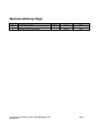
Revision (History) Page
Rev.
A
B
Description of Change
New Release
Revision to Text and Graphics
Service Manual Welch Allyn Fiber Optic Headlight System
Introduction
ECN #
5-34457
Date
1/14/97
9/1/09
Initial
JSJ/MD
DD
Page 2
To Service Personnel:
The information in this manual is subject to change without notice and should not be
construed as a commitment by Welch Allyn, Inc.
Welch Allyn assumes no responsibility for any errors that may appear in this manual. If
the product and/or its operation varies significantly from any description herein, please
contact the Welch Allyn Product Service Department at 4619 Jordan Road, Skaneateles
Falls, New York 13153-0187, 1 866-801-8428, (315) 685-2993
This product has been designed to provide a high degree of safety and reliability.
However, we cannot guarantee against the deterioration of components due to aging and
normal wear.
All service and repairs must be performed by authorized Welch Allyn personnel or
agents, using Welch Allyn replacement parts. Failure to do so will invalidate the product
warranty.
Authorized service centers should refer to repair specifications for proper test and device
history record requirements.
Please refer to the product warranty for specific coverage.
Welch Allyn, Inc.
4619 Jordan Road
Skaneateles Falls, New York 13153-0187
USA
1 866-801-8428
(315) 685-2993
Service Manual Welch Allyn Fiber Optic Headlight System
Introduction
Page 3
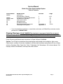
Service Manual
Welch Allyn Fiber Optic Headlight System
Table of Contents
Part Number
49540
49540
495591-502
49543
all
all
all
all
•
Model name
Luminaire
Disassembly / Repair
Suspension Repair/Adjustment
Headband Assembly
Fiber optic cable
Required tools
Problem Solving
Recommended spare parts
Drawings and Figures
Section
Page
1
1
2
2
3
4
Appendix A
Appendix A
6-11
11
12
12
13
14
15-16
If you have technical questions, or need other assistance, call Welch Allyn customer service
personnel at 1-866-801-8428.
Cleaning Warnings: DO NOT IMMERSE the luminaire in any type of liquid. Do not spray it
heavily with any type of liquid. The liquid might enter the luminaire and create a service problem.
DO NOT AUTOCLAVE the whole luminaire. Only the joystick is autoclavable separately.
Follow Cleaning and Maintenance instructions in Owner's Manual PN495608.
Caution: Turn off light source before disconnecting fiber optic bundle from headlight or light source.
Clean exterior surfaces of luminaire, headband, and fiber optic bundle by wiping clean with any of these
solutions: Banicide, Cidex, Cidex Plus, Cidex 7, Metracide, 10% Wescodyne, 10% chlorine bleach, 70%
Isopropyl alcohol, Wavecide01, mild soap and water solution.
Service Manual Welch Allyn Fiber Optic Headlight System
Introduction
Page 4
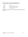
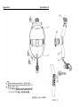
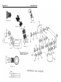
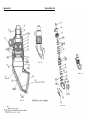
Table of Reference Drawings (Appendix A)
Drawing #
Description
495540
Welch Allyn Headlight Main Assembly . . .
495570
Suspension / Luminaire Assembly ......
495550
Luminaire Assembly .................
Note that drawings within this manual are for reference only. Consult factory for current
revisions.
Service Manual Welch Allyn Fiber Optic Headlight System
Introduction
Page 5
Section 2
Disassembly and Reassembly
Abstract of disassembly and reassembly of 49540 Luminaire:
The whole luminaire can be disassembled with the exception of the mirror and back plate which
are pinned and glued to the bottom housing. If moisture is present in the luminaire, replace the
iris assembly and clean the lenses by following instructions in this manual. With the exception of
the mirror, all components can be replaced as necessary.
The following is the process for completely disassembling and reassembling the luminaire for 'O'
ring replacement. ‘O’ rings are used not to seal out moisture but to provide a smooth moveable
connection between parts. Only replace 'O' rings if they are worn, cracked, stretched out or
missing. If the iris control sleeve is too loose, then the ‘O’ rings have failed.
1.1
Removing O rings:
__Unscrew joystick from the lower housing.
__Unscrew the bezel from the luminaire. Use the appropriate collet or equivalent.
The bezel is glued on.
__Unscrew the top nut. Use collet or equivalent.
__Pull the top cap off of lens housing.
__Remove ‘O’ rings.
1.2
Remove Bottom Housing:
__Unscrew bottom housing from lens housing. These parts are held together
using a thread locking adhesive. Use of a collet will be needed to break the
bind of the threadlocker.
Note: The back plate and the mirror cannot be replaced as they are pinned and glued
into the bottom housing. If the mirror is broken or loose, replace the complete
bottom housing assembly.
1.3
Remove Iris Assembly:
__Unscrew the small pin in the side of the control sleeve. Use 1/16" flat blade
screwdriver.
Note: If the iris pin is sheared, it might be removed by grabbing it with a small diagonal
cutters and unscrewing it. If not, replace lens housing Asy.
__Pull control sleeve from the lens housing.
__Remove 'O' rings.
__Unscrew the iris retaining nut using the Welch Allyn tool T-14452 or equivalent.
Service Manual Welch Allyn Fiber Optic Headlight System
Page 6
Section 2
Disassembly and Reassembly
__Heat the 2-56 set screw holding the iris in place before attempting to loosen it.
The setscrew can be heated by inserting the hex key into the setscrew and
applying heat from a soldering iron to the hex key wrench.
__Unscrew the 2-56 set screw holding the iris in place. Use a .035" hex key.
__Remove the iris.
1.4
Remove Condensing Lenses and Spacers
__Heat the three 2-56 set screws before loosening due to the threadlocker that
is used. The set screw can be heated by inserting the hex key into the
setscrew and applying heat from a soldering iron to the hex key wrench. If the
set screws become stripped, then the entire lens and iris assembly will need
to be replaced.
__Unscrew the three 2-56 set screws from the lens housing. Use a .035" hex
key.
__Remove: the spacer, condensing lens, spacer, and small condensing lens.
Service Manual Welch Allyn Fiber Optic Headlight System
Page 7
Section 2
Disassembly and Reassembly
Re-assembly of model 49540 Luminaire
Special Notes for Reassembly of Luminaire:
•
•
•
•
1.4
Refer to assembly drawing 495550 in this manual.
Use new set screws and 'O' rings when reassembling luminaire.
Remove any threadlocking adhesive from parts by chasing threads with taps or dies.
Do not touch lenses or mirror with fingers. Clean them with cotton swabs and lens
cleaner.
Install Condensing Lenses and Spacers
__Insert clean condensing lens into the lens housing so that the convex portion is
up.
__Insert a condensing lens spacer into the lens housing so the large diameter is
facing up. Push it down onto the condensing lens.
__Insert the next lens (this lens is the same on both sides) into the lens housing
on top of the condensing lens spacer.
1.5
Install Iris assembly
__Insert the iris spacer into the lens housing, chamfered end first. Push it down so
it seats on the lens fully.
__Compress the spacers and lenses together using T14601 or equivalent. At the
same time, dip a set screw into the Loctite 425 threadlocker and Install it into
one of the three holes in the lens housing using a .035" Hex wrench.
__Install the iris into the lens housing, with the retaining clip of the iris assembly
facing upwards. There is a slot in the side of the iris which has a tapped hole
located in it. Align this tapped hole with the slot in the lens housing.
__Screw T14600 through the slot in the lens housing and into the iris; finger
tighten. Note: This is temporary and will be removed after the iris is locked into
place with the iris retainer.
__Insert T14448 into the lens housing so that the pin in the center of the tool is in
the iris opening and the rubber part of the tool rests on the iris. Apply light
downward pressure to T14448 and at the same time, rotate the tool clockwise.
Rotating the tool will cause the iris pin tool 14600 to rotate until it contacts the
end of the slot in the lens housing. Continue rotating the tool until the iris
opening closes down onto the pin of T14448.
__Rotate the iris counter clockwise using T14600 until the tool contacts the
opposite side of the slot. Hold T14448 steady while performing this operation.
__Install a set screw with threadlocker Loctite 425 into the top threaded hole on the lens
housing using a .035" hex wrench; while at the same time, apply firm pressure
downward with T14448. Note: Over tightening of this set screw will cause the iris to
bind.
Service Manual Welch Allyn Fiber Optic Headlight System
Page 8
Section 2
Disassembly and Reassembly
__Remove tool T14448. Apply 2 to 3 drops of Loctite 425 threadlocker to the iris
retainer threads, then Install the iris retainer using T14452.
Note: When the iris is at full closed position, a .090" diameter pin should not go through the
hole in the center of the iris. Open and close the iris; the operation should be smooth.
1.6
Assemble Bottom Housing to Lens Housing
__Open the iris to full open position and blow out any dust in the lens housing
assembly using an Aero duster or equivalent.
__Close iris. Blow any dust out of the bottom housing assembly with an aero
duster.
__Apply 3 to 4 drops of Loctite 425 threadlocker to the large external threads of
the lens housing, and screw it into the bottom housing. Tighten the
assemblies together with the appropriate collet.
__Place the fiber optic cable leading from the Solarc Light Source into the top of
the luminaire assembly.
__Inspect the spot for any dirt or dark spots by shinning onto a white piece of
paper. Also Rotate the iris and check for proper operation. Any small dust
spots not noticed within 2 seconds are generally acceptable. Large, dark or
hair-like spots are not acceptable.
1.7
Control Sleeve and Top Cap
__Install (2) large O-rings into the lower grooves on the lens housing.
__Install (1) large O-ring onto the top of the first shoulder of the lens housing.
__Apply a light coat of grease to all (3) O-rings.
__Assemble the control sleeve over the lens housing and down to the O-rings.
Rotate the control sleeve so that the hole in the side of it is positioned above
the threaded hole in the iris; seen through the slot in the lens housing.
__Push control sleeve down over the O-rings until seated; being careful not to
rotate the parts.
__Apply (1) drop of Loctite Adhesive to the threads of an iris pin and install
through the hole in the control sleeve and into the iris. Tighten w/ a screw
driver until flush or just below.
Service Manual Welch Allyn Fiber Optic Headlight System
Page 9
Section 2
Disassembly and Reassembly
__ Rotate control sleeve back and forth to spread grease and check for
freedom of movement.
__ Install (1) large O-ring onto the lens housing and push down until seated on
top of the control sleeve.
__ Install (2) large O-rings into the lower exposed grooves on the lens housing.
__ Install (1) small O-ring onto the lens housing so that it sit on the shoulder just
above the last large O-ring.
__Apply a generous coat of grease to the 2 lower O-rings.
__Apply a coat of grease to the inside of the top cap.
__ Install a top cap onto the lens housing so it rests on the O-rings. Rotate the
top cap while pushing it down over the O-rings. Continue until seated.
__ Install (1) small O-ring down on top of the top cap.
__Apply 2-3 drops of Loctite 425 Threadlocker to the lens housing threads.
__ Install the top cap nut onto the lens housing and tighten with the appropriate
collet or equivalent.
__ Rotate the top cap a few turns to make sure it rotates smoothly.
Service Manual Welch Allyn Fiber Optic Headlight System
Page 10
Section 2
Disassembly and Reassembly
Abstract of disassembly and reassembly of 49540 luminaire suspension: The following is the
process for adjusting or repairing the luminaire suspension. In most cases the end user will
probably indicate that the luminaire no longer stays where it is put. This condition is caused by
wear to the friction washers in the suspension mechanism or loosening of the assembly
screws. The assembly screw(s) can be tightened to compensate for the wear of the washers or
in severe cases, the washers will need to be replaced.
Special notes for Repairing the Luminaire Suspension:
•
Refer to assembly drawing 495570 in this manual for proper reassembly and torque
specifications.
•
Reapply threadlocking adhesive (Loctite 425) to any screws that are tightened or
loosened.
__Remove the set screws located inside the three pivot nuts, using a 1/16" hex
key.
__Loosen the three pivot nuts to break any of the threadlocker free so that the
nut turns freely, and blow out any loose debris left from the old threadlocker.
__Tighten the three pivot nuts to the specified torque as described on drawing
495570.
__Apply a drop of Loctite 425 threadlocker onto the threads of a set screw and
install it into one of the pivot nuts. Tighten with a 1/16" hex wrench. Repeat
for the remaining two screws.
Service Manual Welch Allyn Fiber Optic Headlight System
Page 11
Section 3
Headband Adjustments and Repair
Abstract of adjustment / repair of the Headband:
The following is the process for adjusting or repairing the headband. There are only two
replaceable components of the headband assembly, the three vinyl pads (1set) and the
fiber-optic clips. The fit adjustment controls can be adjusted if the knobs are too hard to
turn or if the headband will not maintain its fit (Loosens).
Special Notes for Repairing the Headband:
•
Refer to assembly drawing 495540 in this manual for further details.
•
If the vinyl pads need to be removed and reused, be sure to release snaps by pushing
a fingernail or equivalent between the two halves of the snap. The vinyl is extremely
thin and will tear if pulled on directly.
2.1 Comfort/Fit Adjustment Knob:
__Tighten the screw in the center of the adjustment knob if the headband
continues to loosen.
__Loosen the screw in the center of the adjustment knob if the knob is too hard
to turn.
2.2 Fiber Optic Clips:
__Remove the vinyl pad on the top support of the headband assembly. See
note above.
__Unscrew the two screws that hold the respective clip in place and Remove
the clip.
__Reassemble in reverse order.
Special Notes for the Fiber Optic Bundle:
The Fiber optic bundle (49543) is a multi-fiber cable which transmits the light generated at the
light source into the luminaire assembly. There is no repair for this item. It must be replaced if
the fibers become damaged.
Note: Refer to owner's manual (495608) for cleaning and disinfection.
Broken Fibers:
__Hold one end of the fiber bundle up to a light and look at the other end. Dark
areas are broken fibers. The fiber optic cable will need to be replaced if the
dark area covers 20% or more of the entire bundle surface.
Service Manual Welch Allyn Fiber Optic Headlight System
Page 12
Section 4
Tools and Equipment List
Tools and Equipment List:
General purpose tools / supplies:
1/16" hex key
.035" hex key
Peer #7 tweezers
# 4 Flat Blade screwdriver
#2 Phillips screwdriver
#1 Phillips screwdriver
Collet Block
5C Collet for Top Nut Cap (.382")
5C Collet for Lens Housing (.438'')
5C Collet for Bezel (1.06")
Jeweler's's flat-blade screwdriver (1.5mm x 40mm) for Iris Pin.
Aero Duster ("canned air") or equivalent. Compressed air is not recommended due to oils and
moisture that are often found in compressed air.
Welch Allyn tools and fixtures:
T14600: Extended iris pin.
T14448: Iris aperture adjustment tool.
T14452: Spanner wrench for iris retainer nut.
49501 Solarc Light Source
49543 MFI Fiber Optic Cable
Service Manual Welch Allyn Fiber Optic Headlight System
Page 13
Section 5
Problem Solving
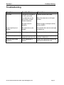
Troubleshooting
Symptom
Possible Cause
Low Light
Damage has occurred to
the fiber optic cable.
Replace the fiber optic cable.
The attenuator on the
light source is turned
counter clockwise.
Adjust the attenuator to full bright
position.
The light source is
defective.
Repair the light source per service
manual 495621.
Output Light Spot not
defined.
The luminaire may be
flooded.
Disassemble the luminaire and repair
as necessary.
Spot size control is hard to
turn.
The o-rings are binding.
Replace and lubricate all o-rings.
Luminaire droops.
Friction washers in
suspension are worn out.
Readjust suspension or replace
washers if necessary.
Headband won't keep
desired fit.
The fit adjustment is
slipping.
Tighten the adjustment screw on the
appropriate adjustment knob
Service Manual Welch Allyn Fiber Optic Headlight System
Procedure
Page 14
Appendix A
Bubble #
0002
0004
0006
0007
0001
0002
0003
0004
0005
0006
0007
0008
0009
0001
0002
0003
0004
0005
0006
0007
0008
0009
0010
0011
0012
0013
0014
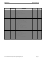
Spare Parts List
Part Number
495562
495594
495608
49571
495591-502
106102-25
495565-1
495596-502
495573-4
495572-3
106142-8
106103-32
495571-3
495577
495575
495574
106113-17
495507-3
495506-2
495505-3
106104-33
106104-32
495513
495504-1
495901
495509
495902
495510
710114
495515
495517-1
Description
BUNDLE CLIPS
WASHER, COUNTERSUNK
MANUAL
JOYSTICK ASSY
HEADBAND ASSY TAMPO
FHPS 6-32 X.312
LABEL
PAD SET
MOUNT,HEADBAND-ANODIZED
LINKAGE, LONG-ANODIZED
WASHER, BELVILLE (.375 OD)
WASHER, FLAT FRICTION
LINKAGE, SHORT-ANODIZED
SPACER, HEADBAND MOUNT
NUT, PIVOT
SCREW, PIVOT
SET SCREW (#6-32 X .125)
TOP CAP NUT ANODIZED
TOP CAP ANODIZED
CONTROL SLEEVE ANODIZED
O-RING
O-RING
SPRING CLIP, FERRULE
LENS HOUSING
CONDENSER LENS #1
SPACER-CONDENSER LENS
CONDENSER LENS #2
SPACER-IRIS
2-56 X 1/16 LG SET SCREW
IRIS DIAPHRAGM
PIN,IRIS
Service Manual Welch Allyn Fiber Optic Headlight System
Quantity
Luminaire
4
2
1
1
1
2
1
1
1
2
6
6
2
1
3
3
3
1
1
1
2
6
1
1
1
1
1
1
4
1
1
Drawing
Number
495540
495540
495540
495540
495570
495570
495570
495570
495570
495570
495570
495570
495570
495550
495550
495550
495550
495550
495550
495550
495550
495550
495550
495550
495550
495550
495550
Page 15
Appendix A
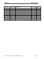
Spare Parts List
Bubble #
Part Number
0015
0016
0017
0018
0019
0020
0021
0022
0023
0024
0026
0027
0028
495516-1
495501-9
495512
495903
495502-3
495904-1
495503-6
106126-22
M30397
M30398
M30328
M30373
M40156
Description
RETAINER, IRIS
BOTTOM HSG-ANODIZED
JOYSTICK INSERT
OBJECTIVE LENS #3
BEZEL-OBJ LENS ANODIZED
MIRROR
MIRROR PLATE ANODIZED
SPIRAL PIN, (.033 DIA X .125)
LOCTITE 330
LOCTITE 738 ACTIVATOR
LOCTITE 262-31
LOCTITE 425 ASSURE THDLCKER
DOW CORNING 3452 LUBE
Service Manual Welch Allyn Fiber Optic Headlight System
Quantity
Luminaire
1
1
1
1
1
1
1
2
0
0
0
0
0
Drawing
Number
495550
495550
495550
495550
495550
495550
495550
495550
495550
495550
495550
495550
495550
Page 16
Appendix A
Spare Parts List
Appendix A
Spare Parts List
Appendix A
Spare Parts List