1
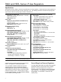
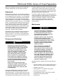
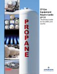
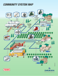
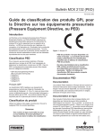
Instruction Manual
MCK 2141
R600 and HSRL Series LP-Gas Regulators
February 2013
R600 and HSRL Series Instruction Manual
!
WARNING
Failure to follow these instructions or
to properly install and maintain this
equipment could result in an explosion
and/or fire causing property damage and
personal injury or death.
Fisher® equipment must be installed,
operated, and maintained in accordance
with federal, state, and local codes and
Fisher instructions. The installation in most
states must also comply with NFPA No. 54
and 58 standards.
TYPE R622
Only personnel trained in the proper
procedures, codes, standards, and
regulations of the LP-Gas industry should
install and service this equipment.
TYPE R642
Things to tell the gas customer:
2. Show the customer the shutoff valve on the
container. The customer should close this valve
immediately if gas is smelled, appliance pilot lights
fail to stay on or appear higher than usual or any
other abnormal situation occurs.
3. Tell the customer to call your company to service the
regulator if the regulator vents gas or a leak develops
in the system. Only a qualified gas service person
should install or service the regulator.
Introduction
Scope of the Manual
This Instruction Manual covers Installation and
Maintenance for the R600 and HSRL Series regulators,
which includes first stage, second stage, two psig service,
integral two- stage and integral two psig service regulators
TYPE HSRL
Figure 1. Types R622, R642, and HSRL Series Regulators
used on LP-Gas vapor service applications. They are not
to be used on liquid service.
Description
First Stage and 2 psig / 0.14 bar
Service Regulators
The Types R622H, R622E, and R652E regulators are
designed for high pressure (pounds per square inch)
vapor service. These regulators have high capacity
internal relief valves.
When used on first stage service, the Type R622H
regulator reduces container pressure to 10 psig / 0.69 bar
for a second stage regulator. On final stage service the
www.fisherregulators.com
D450133T012
1. Show the customer the vent or vent assembly or
vent tube. Stress that this opening must remain
unobstructed at all times. Tell the customer to check
the vent opening after a freezing rain, sleet storm, or
snow to make sure ice has not formed in the vent.
R600 and HSRL Series LP-Gas Regulators
Specifications
Specifications section, Tables 1 and 2 list the specifications for these regulators. Contact the factory if the regulator is to
be used on any service other than LP-Gas, natural gas, or air. The following information is located on the spring case:
Type number, orifice size, spring range, and date of manufacture.
Pressure Taps Size Restriction
R600 Series: 1/8 NPT: #54 (0.055 inch / 1.40 mm)
Drill on outlet and inlet
HSRL Series: None
Orifice Sizes
R600 Series (Except R632A and R632E Series):
7/32 inch / 5.6 mm
R632A and R632E Series: 0.256 inch / 6.5 mm
HSRL Series: 3/8 inch / 9.5 mm
Wide-open Cg for Relief Sizing
R600 Series: 38
HSRL Series: 105
Maximum Allowable Inlet Pressure(1)
Types R622H, R632A, and R632E: 250 psig / 17.2 bar
Types R622E and R652E: 10 psig / 0.69 bar
Types R622, R642, R652, and HSRL Series:
10 psig / 0.69 bar
Maximum Emergency Inlet Pressure(1)
Types R622H, R632A, and R632E: 250 psig / 17.2 bar
Types R622E and R652E: 15 psig / 1.0 bar
Types R622, R642, R652, and HSRL Series:
15 psig / 1.0 bar
Temperature Capabilities(1)
R600 and HSRL Series: -20 to 160ºF / -29 to 71ºC(2)
Pressure Registration
Internal
Outlet Pressure Standard Setpoint
Types R622, R642, R652, and HSRL Series:
11 inches w.c. / 27 mbar
Type R632A:
First Stage: approximately 8 psig / 0.55 bar at
75 psig / 5.2 bar, 65 SCFH / 1.84 Sm3/h
Second Stage: 11 inches w.c. / 27 mbar
Outlet Pressure Standard Setpoint (continued)
Type R632E:
First Stage: approximately 8 psig / 0.55 bar at
75 psig / 5.2 bar, 65 SCFH / 1.84 Sm3/h
Second Stage: 2 psig / 0.14 bar
Types R622E and R652E: 2 psig / 0.14 bar
Type R622H: 10 psig / 0.69 bar, 5 psig / 0.35 bar
Outlet Pressure Spring Range
Types R622, R642, and R652:
7.5 to 9.5 inches w.c. / 19 to 24 mbar,
9 to 13 inches w.c. / 22 to 32 mbar,
13 to 20 inches w.c. / 32 to 50 mbar,
16 to 40 inches w.c. / 40 to 99 mbar
Type R632A:
First Stage: non-adjustable
Second Stage: 9 to 13 inches w.c. / 22 to 32 mbar
Type R632E:
First Stage: non-adjustable
Second Stage: 1 to 2.2 psig / 69 mbar to 0.15 bar
Types R622E and R652E:
1 to 2.2 psig / 69 mbar to 0.15 bar
Type R622H: 8 to 12 psig / 0.55 to 0.83 bar,
4 to 6 psig / 0.28 to 0.41 bar
HSRL Series: 9 to 13 inches w.c. / 22 to 32 mbar
Approximate Weight
Type R622H with POL Inlet:
1.7 pounds / 771 grams
Types R632A and R632E with POL inlet:
2.9 pounds / 1310 grams
Types R632A and R632E with NPT Inlet:
2.5 pounds / 1125 grams
All Other R600 Series: 1.4 pounds / 635 grams
HSRL Series: 4.5 pounds / 2.0 kg
1. The pressure/temperature limits in this Instruction Manual or any applicable standard limitation should not be exceeded.
2. Product has passed Fisher® testing for lockup, relief start-to-discharge and reseal down to -40ºF / -40ºC.
regulator reduces container pressure for a high pressure
burner. The regulator is normally painted RED.
Second Stage Low Pressure Regulators
The Type R622E or R652E standard outlet pressure
setting is 2 psig / 0.14 bar. The regulator is painted
PALM GREEN with a WHITE CAP. It is an intermediate
stage regulator that reduces 10 psig / 0.69 bar first stage
pressure to 2 psig / 0.14 bar. They are used on 2 psig /
0.14 bar pressure systems. The Types R622E and R652E
are not suitable for first stage service.
The Types R622, R642, R652, and HSRL Series regulators
provide low pressure, inches of water column, delivery
pressures. They are normally set at 11-inches w.c. /
27 mbar pressure. They have high capacity internal relief
valve construction. The regulators are normally painted
PALM GREEN. The units differ in construction and
capacity rating.
2
R600 and HSRL Series LP-Gas Regulators
Integral Two-stage Regulator
The Type R632A integral two-stage regulator contains
a non-adjustable first stage regulator on the inlet. The
second stage provides 11-inches w.c. / 27 mbar outlet
pressure. The second stage portion has a high capacity
internal relief valve construction. The first stage does not
have an internal relief valve. The regulators are normally
painted GRAY with a BLACK CAP.
VENT POINTED DOWN
Integral Two psig Service Regulator
The Type R632E integral two psig service regulator
contains a non-adjustable first stage regulator on the
inlet. The second stage provides 2 psig / 0.14 bar
outlet pressure. The second stage portion has a high
capacity internal relief valve construction. The first stage
does not have an internal relief valve. The regulators
are normally painted GRAY with a WHITE CAP and
White 2-psig STICKER.
3 FEET /
0.913meter
T14446-A2
Figure 2. Regulator with Vent Pointed Down
Installation
!
accumulation of gas which could result in
personal injury or property damage.
WARNING
Never use a Type R622H, R622E, R632E,
or R652E (pounds-to-pounds) regulator
on low pressure (inches of water column)
service because personal injury or
property damage could occur. The
Types R622E and R652E are not suitable
for use as a “first stage” regulator.
All vents should be kept open to permit
free flow of air in and out of the regulator.
Protect vent openings against the entrance
of rain, snow, ice formation, paint, mud,
insects, or any other foreign material that
could plug the vent or vent line.
LP-Gas may discharge to the atmosphere
through the vent. An obstructed vent
which limits air or gas flow can cause
abnormally high pressure that could
result in personal injury or property
damage. Failure to use a vent line on
Indoor Installations can cause a hazardous
General Installation Instructions
Before installing the regulator,
•
Check for damage, which might have occurred
in shipment.
•
Check for and remove any dirt or foreign material,
which may have accumulated in the regulator body.
Table 1. Relief Valve Specifications
TYPE
TYPICAL SETPOINT
psig
bar
NOMINAL RELIEF VALVE
START-TO-DISCHARGE
psig
bar
MAXIMUM INLET PRESSURE TO NOT EXCEED OUTLET
PRESSURE WITH DISC REMOVED
Inlet Pressure
Maximum Outlet Pressure
psig
bar
15
1.0
50
3.4
R632A(1)
250
17.2
R632E(1)
250
17.2
50
3.4
HSRL
R622 and R642
11 inches w.c.
27 mbar
1
69 mbar
psig
bar
2
0.14
5
0.34
R652
R622E
2
0.14
3.5
0.24
10
0.69
20
1.37
R652E
R622H
Not Applicable
1. For integral two-stage regulators, the second stage disc is removed.
3
R600 and HSRL Series LP-Gas Regulators
Table 2. Capacity, Connection Sizes, and Vent Orientation
REGULATOR
APPLICATION
TYPE
NUMBER
CAPACITY
BTU/HR
PROPANE(1)
INLET
CONNECTION
OUTLET
CONNECTION
R622-BCF
875,000
1/2-inch FNPT
1/2-inch FNPT
R642-DFF
900,000
R652-DFF
1,000,000
3/4-inch FNPT
3/4-inch FNPT
R622-CFF
Second Stage
OUTLET
PRESSURE
SETTING
11 inches w.c. /
27 mbar
1/2-inch FNPT
1,400,000
R622-DFF
R622-CFGXA
Over Inlet
3/4-inch FNPT
1,125,000
HSRL-BFC(2)
HSRL-CFC(2)
3/4-inch FNPT
18 inches w.c. /
45 mbar
1-inch FNPT
11 inches w.c. /
27 mbar
1/2-inch FNPT
3/4-inch FNPT
2,100,000
1-inch FNPT
R632A-BCF
1/4-inch FNPT
850,000
1/2-inch FNPT
R632A-HCF
FPOL
R632A-CFF
950,000
1/4-inch FNPT
R632A-JFF
850,000
FPOL
11 inches w.c. /
27 mbar
3/4-inch FNPT
Integral
Two-Stage
R632A-BCFXA
1/4-inch FNPT
850,000
1/2-inch FNPT
R632A-HCFXA
Integral
2 psig / 0.14 bar
Service
FPOL
R632A-CFFXA
950,000
1/4-inch FNPT
R632A-JFFXA
850,000
FPOL
R632E-BCH
850,000
1/4-inch FNPT
R632E-HCH
900,000
FPOL
11 inches w.c /
27 mbar
First Stage(3):
Down
Second Stage:
Over Outlet
First Stage(3):
Opposite gauge taps
3/4-inch FNPT
Second Stage:
Opposite gauge taps
1/2-inch FNPT
First Stage(3):
Down
2 psig / 0.14 bar
R632E-CFH
1/4-inch FNPT
850,000
Second Stage:
Over Outlet
3/4-inch FNPT
R632E-JFH
2 psig / 0.14 bar
Service
3/4-INCH NPT
SCREENED
VENT STANDARD
LOCATION
FPOL
R622E-BCH
1,250,000
R622E-DCH
1,500,000
R652E-DFH
1,400,000
R622H-BGK
2,000,000
1/2-inch FNPT
1/2-inch FNPT
3/4-inch FNPT
3/4-inch FNPT
2 psig / 0.14 bar
Over Inlet
5 psig / 0.35 bar
1/2-inch FNPT
R622H-BGJ
1/2-inch FNPT
R622H-HGJ
First Stage
2,100,000
10 psig / 0.69 bar
R622H-HGJKA
Over Outlet
FPOL
R622H-JGK
5 psig / 0.35 bar
2,250,000
R622H-JGJ
3/4-inch FNPT
10 psig / 0.69 bar
R622H-DGJ
2,400,000
3/4-inch FNPT
1. Capacities Based on:
Second Stage: 10 psig / 0.69 bar inlet pressure and 2 inches w.c. / 5 mbar droop.
Integral Two-stage: 30 psig / 2.1 bar and 2 inches w.c. / 5 mbar droop.
Integral Two psig Service: 30 psig / 2.07 bar and 20% droop.
2 psig / 0.14 bar Service: 10 psig / 0.69 bar inlet pressure and 20% droop.
First Stage: 30 psig / 2.1 bar inlet pressure and 20% droop.
2. Straight globe valve body configuration.
3. Integral First Stage Vent size: 7/16-24 UN thread for 1/4-inch OD copper tube inverted flare fitting.
4
•
Replace old pigtails. Blow out any debris, dirt or copper
sulfate in the copper tubing and the pipeline.
•
Apply pipe compound to the male threads of the pipe
before installing the regulator.
•
Make sure gas flow through the regulator is in the same
direction as the arrow on the body. “Inlet” and “Outlet”
connections are clearly marked.
Installation Location
•
The installed regulator should be adequately
protected from vehicular traffic and damage from
other external sources.
•
Install the regulator with the vent pointed vertically
down, see Figure 2. If the vent cannot be installed
in a vertically down position, the regulator must be
installed under a separate protective cover. Installing
R600 and HSRL Series LP-Gas Regulators
T14447-A2
Figure 3. Tank Installation
the regulator with the vent down allows condensation
to drain, minimizes the entry of water or other debris
from entering the vent, and minimizes vent blockage
from freezing precipitation.
•
•
•
Do not install the regulator in a location where there can
be excessive water accumulation or ice formation, such
as directly beneath a down spout, gutter, or roof line
of building. Even a protective hood may not provide
adequate protection in these instances.
TO
APPLIANCE
Install the regulator so that any gas discharge through
the vent or vent assembly is over 3 feet / 0.91 meter
horizontally from any building opening below the level
of discharge.
VENT
ASSEMBLY
Install the regulator high enough above ground level
at least 18 inches / 45 cm - so that rain splatter cannot
freeze in the vent.
Regulators Subjected to Heavy
Snow Conditions
Some installations, such as in areas with heavy snowfall,
may require a hood or enclosure to protect the regulator
from snow load and vent freeze over.
VENT LINE
VENT OPENING
MUST BE AT LEAST
3 FEET / 0.91 meter
HORIZONTALLY
FROM ANY
BUILDING OPENING
BELOW IT
BASEMENT
FROM FIRST
STAGE REGULATOR
Horizontally Installed Regulators
Horizontally mounted regulators, such as found in single
cylinder installations and ASME tanks, must be installed
beneath a protective cover or under the ASME tank
dome, refer to Figure 3. If possible, slope or turn the
vent down sufficiently to allow any condensation to drain
out of the spring case. Be careful that the slot in the
tank dome or protective cover for the regulator’s outlet
piping does not expose the vent to the elements. The
first stage vent on the Types R632A and R632E should
be pointed down.
T14445-A2
Figure 4. Basement Installation
5
R600 and HSRL Series LP-Gas Regulators
END OF REGULATOR VENT
TUBE LOCATED AT TOP INSIDE
OF HOUSING DOME COVER
GRADE GROUND DOWNWARD AND
SLOPING AWAY FROM HOUSING DOME.
THIS PREVENTS WATER COLLECTING
AND RUNNING INTO OR STANDING
AROUND HOUSING DOME.
2 INCHES / 5.1 cm
MINIMUM
REGULATOR ADJUSTMENT
CLOSURE CAP MUST BE TIGHT.
WATER MARK LEFT IN HOUSING DOME AT LEVEL ABOVE REGULATOR VENT, OR END OF
VENT TUBE REQUIRES REPLACEMENT OF REGULATOR. INSTALL REGULATOR PROPERLY.
T14448-A2
Figure 5. Underground Installation
Meter Installations
Type R642 regulators have an angle body that makes it
easy to install on to a gas meter instead of piping leading
directly into a building.
Meter and Type R642 with Vent over
Regulator Inlet:
Install the regulator per instructions given in the previous
section “Installation Location”.
Meter and Type R642 with Vent over the Regulator
Outlet and Installed over the Top of the Meter:
This installation orientation will put the Type R642
regulator vent in a vertical down position, but very close
to the top of the gas meter. The regulator vent may
become blocked during a freezing rain storm or heavy
snows. Therefore, some type of protective cover should
be installed over the regulator and meter or vent piping
should be installed so that the vent remains open.
Meter and Type R642 Regulator Installed Indoors:
relief valve. Vent lines should be at least 3/4-inch NPT
pipe or 3/4-inch NPT size, Gray PVC Schedule 40 Rigid
Non-metallic Electrical Conduit for above Ground Service,
per UL® 651. To install the vent line, remove the vent
screen and apply a good grade of pipe dope to the male
threads of the line. Vent lines should be as straight as
possible with a minimum number of bends.
Underground Installations
CAUTION
Types R632A and R632E integral
regulators require 2 vent tubes, one on
the first stage vent and one on the second
stage vent, when installed on underground
tanks. Failure to use 2 separate vent tubes
can result in early regulator failure and/
or over pressuring the second stage that
could result in fires or personal injury.
Regulators installed in the dome of an underground
container require a vent tube to prevent water from
entering the regulator spring case, see Figure 5.
Note
Pipe the regulator vent per the section “Indoor Installations”.
Indoor Installations
By code, regulators installed indoors have limited inlet
pressure, and they require a vent line to the outside of the
building, see Figure 4. A vent assembly, such as
Fisher® Y602 Series, should be used on the end of the
vent line. The same installation precautions, previously
discussed throughout this manual for the regulator vent,
apply to the end of the vent tube assembly. Vent lines
must not restrict the gas flow from the regulator’s internal
6
Types R632A and R632E integral regulators
installed on underground tanks require the
use of 2 vent tubes, one for the first stage
vent (1/4-inch OD copper tube inverted flare
connection: 7/16-24 UN thread) and the
other for the second stage vent (3/4 NPT) of
the regulator.
Remove the vent screen and install a vent tube. The
vent tube must be run from the regulator vent to above
the maximum water table. The vent tube opening must
terminate at the extreme top inside of the dome cover.
R600 and HSRL Series LP-Gas Regulators
Make sure the regulator’s closing cap is on tightly, and
maintain drainage away from the dome at all times.
Adjustment
Each regulator is factory set. If it becomes necessary to
increase the outlet pressure, remove the closing cap and
turn the adjustment screw clockwise. Turn the adjusting
screw counterclockwise to decrease the outlet pressure.
The first stage portion of the Types R632A and R632E
integral regulators is non-adjustable. The outlet pressure
plug may be removed using a 7/16-inch / 11 mm hexagon
wrench. The pressure tap is restricted, so the plug can
be removed with pressure on the outlet of the regulator.
Install a pressure gauge to determine the regulator’s
outlet setting during adjustment, (Actual pressure at the
second stage regulator may be less due to line loss.)
After setting, reinstall the pipe plug and replace the
closing cap. Check the plug for leakage.
or foreign material on the orifice. The amount of internal
relief protection provided varies with the regulator type
and the cause for the overpressure relief valve operation.
When the internal relief valve opens, gas escapes to the
atmosphere through the regulator’s vent.
Some type of additional external overpressure protection
must be provided if the outlet pressure in an overpressure
condition exceeds the inlet pressure rating of the gas
system or downstream equipment. Common methods
of external overpressure protection include relief
valves, monitoring regulators, shutoff devices, and
series regulation.
Maintenance
!
To avoid personal injury or equipment
damage, do not attempt any maintenance
or disassembly without first isolating
the regulator from system pressure and
relieving all internal pressure.
Inlet pressure may be checked using the inlet pressure
gauge tap and a pressure gauge. Remove the plug
using a 7/16-inch / 11 mm wrench. The pressure tap is
restricted, so the plug can be removed with pressure on
the inlet of the regulator.
Regulators that have been disassembled
for repair must be tested for proper
operation before being returned to service.
Only parts manufactured by Fisher® should
be used for repairing Fisher regulators.
Relight pilot lights according to normal
startup procedures.
Overpressure Protection
!
WARNING
Some type of overpressure protection is
needed if actual inlet pressure can exceed
the outlet pressure rating. Overpressuring
any portion of this equipment above the
limits shown in the Specifications section
may cause damage to regulator parts,
leaks in the regulator, or personal injury
due to bursting of pressure-containing
parts or explosion of accumulated gas.
If any portion of the regulator is exposed
to an overpressure condition that exceeds
the limits in the Specifications section, it
must be inspected for damage that may
have occurred.
Large volumes of gas may discharge
through the regulator vent during internal
relief valve operation, which can, if not
controlled, result in fire or explosion from
accumulated gas.
The R600 and HSRL Series regulators, except for the
first stage of the Types R632A and R632E, contain
internal relief valves. The internal relief valve in all units
will give overpressure protection against excessive buildup resulting from seat leakage due to worn parts or chips
WARNING
Due to normal wear or damage that
may occur from external sources,
these regulators must be inspected and
maintained periodically. The frequency
of inspection and replacement of the
regulators depends upon the severity of
service conditions or the requirements of
local, state, and federal regulations. Even
under ideal conditions, these regulators
should be replaced after 20 years from
date of manufacture or sooner should
inspection reveal the need.
Visually inspect the regulator each time a gas delivery is
made for:
•
Improper installation, vent not pointed vertically down or
under a cover; no vent tube on underground systems
•
Plugged or frozen vent
•
Wrong regulator or no regulator in the system
•
Internal or external corrosion
•
Flooded Regulator; water in spring case; regulator
submersed on underground tanks
•
Regulator age
7
R600 and HSRL Series LP-Gas Regulators
•
Any other condition that could cause the uncontrolled
escape of gas
Failure to do the above could result in personal injury or
property damage
Vent Opening
Make sure the regulator vent, vent assembly, or vent tube
does not become plugged by mud, insects, ice, snow,
paint, etc. The vent screen aids in keeping the vent from
becoming plugged, and the screen should be clean and
properly installed.
Water inside Regulators from
Floods, Weather, or Water Table on
Underground Systems
Replace any regulator that has been flooded or has been
submersed below the water table of an underground tank,
have had water in their spring case or show evidence
of external or internal corrosion. Checking for internal
corrosion can be done by removing the closing cap and
with the aid of a flashlight observing the condition of the
relief valve spring, main spring, and internal spring barrel
area. A more detailed examination will require shutting
down of the gas system and the complete removal of the
adjusting screw. Closely examine regulators installed
with their vent horizontal for signs of corrosion. Correct
any improper installations.
Regulator Replacement
Older regulators are more likely to catastrophically
fail because of worn or corroded parts. Replace
R600 and HSRL Series regulators over 20 years of age.
Other service or environmental conditions may dictate
replacement of the regulator before it becomes 20 years
old. Regulators that are installed on underground
systems and in areas that are subject to sea salt
(coastal) atmospheres should be inspected annually
for external and internal corrosion and may require
replacement sooner. Refer to Fisher® Bulletin LP-32 for
additional information.
Regulator Repair
Regulators that have been disassembled for repair
must be tested for proper operation before being
returned to service. Only parts manufactured by Fisher
should be used to repair Fisher regulators. Be sure to
give the complete type number of the regulator when
corresponding with the factory.
The type number, orifice size, and spring range are
on a label attached to the spring barrel. The date of
manufacture is stamped on the regulator. Always provide
this information in any correspondence with your Fisher
Distributor regarding replacement parts or technical
assistance. If construction changes are made in the field,
be sure that the regulator marking is also changed to
reflect the most recent construction.
LP-Gas Equipment
Emerson Process Management
Regulator Technologies, Inc.
USA - Headquarters
McKinney, Texas 75069-1872, USA
Tel: +1 800 558 5853
Outside U.S. +1 972 548 3574
For further information visit www.fisherregulators.com
The Emerson logo is a trademark and service mark of Emerson Electric Co. All other marks are the property of their prospective owners. Fisher is a mark owned by Fisher Controls International LLC,
a business of Emerson Process Management.
The contents of this publication are presented for informational purposes only, and while every effort has been made to ensure their accuracy, they are not to be construed as warranties or
guarantees, express or implied, regarding the products or services described herein or their use or applicability. We reserve the right to modify or improve the designs or specifications of such
products at any time without notice.
Emerson Process Management Regulator Technologies, Inc. does not assume responsibility for the selection, use or maintenance of any product. Responsibility for proper selection, use and
maintenance of any Emerson Process Management Regulator Technologies, Inc. product remains solely with the purchaser.
©Emerson Process Management Regulator Technologies, Inc., 2001, 2013; All Rights Reserved