1
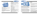
7
1
4. Phase switch. Allows you to change the phase of
your subwoofers from 0° to 180° to help compensate for timing differences between speakers.
2
High Level Input
CX2
2-Way 18dB/Oct Electronic Crossover
120 Hz
100 Hz
80 Hz
50 Hz
Phase
Sub-Woofer
High-Pass
Output Level
Output Level
3
Reverse
5. Mode switch. Allows you to change the subwoofer output between stereo and mono, thus facilitating single subwoofer installations.
Audio
Signal
Source Left
Power
Amplifier
1. Make all connections securely and avoid stretching
any wires or cables that could pull loose later on.
Never make or break any connection with the power
to your amplifier turned on.
CX2
Low-Pass
Mode
5
Mono
Connections
Make connections according to the diagram and note
the following:
Right
80 Hz
100 Hz
120 Hz
140 Hz
4
Normal
Power
High-Pass Amplifier
6. Input jacks. Input from sound source RCA jacks.
Stereo
Min
Min
Max
Max
Power
Input
L
R
6
Sub-Woofer
L Out R
High-Pass
L Out R
8
9
B+ GND
R
10
1. Low-Pass frequency selector. By using this
selector you can choose the Low-Pass crossover
point (50/80/100/120Hz)
2. High-Pass frequency selector. By using this
selector you can choose the High-Pass crossover
point (80/100/120/140Hz)
3. Level Controls. Since the volume of each output
varies upon speaker efficiency variation and main
amplifier output variation, make adjustments using
these controls.
7. High level input. Input from sound source’s speaker leads.
8. Low Pass output jacks. Connect RCA cables to
the subwoofer amplifier.
9. High Pass output jacks. Connect RCA cables to
the Mid-High amplifier.
10. Power connector port. B+ : Connect to the (+)
positive terminal of the car battery. Place a fuse
close to the car battery to protect the vehicle.
GND: Connect to a metal part of the car, or negative (-) terminal of the car battery.
REM: Connect to the remote activating wire of the
radio, or Power antenna wire.
1
This diagram shows you a typical configuration. Two
power amplifiers are required. The Low-Pass output
drives the subwoofers amplifier and the High-Pass output drives a second amplifier for your midrange-/tweeter system. They could also be full range speakers
except now they are relieved of their deep bass duty
which is carried entirely by the subwoofers.
Full frequency performance is accomplished by the two
groups working together without any overlaps or gaps.
One speaker pair picks up as the other is falling off.The
cut-off frequency for each can be set independently with
the multi-position switches. In most cases they should be
set close to the same frequency to avoid unintentional
peaks or valleys in the system response. This common
cut-off frequency is called the “crossover frequency”.
2
2. Make sure the ground connection attaches to bare
metal that is part of the car’s chassis and not a insulated piece of trim. If you experience excessive noise
during operation, its cause will probably trace back
to a poor ground connection.
3. Make all connections to the CX2 before mounting.
4. Disconnect the car battery to prevent short circuits
while making power connections. Insulate all connections to prevent short circuits.
5. Plug the radio’s pre-out RCA plugs into the CX2’s
input jacks, or connect the radio’s speaker outputs
to the High level input on the Molex connectors and
plug into item 7. Do not use both RCA-input and
High Level input at the same time.
Mounting your CX2 Crossover:
The CX2 crossover can be mounted in any position
using the 4 self-tapping screws provided.
•
Vertical mounting provides the best access to the
controls.
•
Mount the CX2 crossover so that it is protected
from vibration, possible water leakage and dust.
What to do if there are problems?
Before removing the crossover, look for the problem in
the list below.
1. No output:
A. Make sure that the RCA connectors are plugged
firmly together.
B. Check the amplifier manuals to check for problems in the amplifiers.
C.Check the power fuse. Both the B+ and the
Remote terminals must have +12V in order for
the CX2 to turn on.You can use a small 12V light
bulb to check for +12V from these terminals to
chassis ground.
D. Make sure that the signal source (radio/cassette/CD-deck) is connected and supplying output.
You can find out if the crossover is working by
plugging one end of a set of RCA patch cords
into the crossover inputs, and briefly tapping the
center pin of each plug on the other end with a
finger. This should make a noise in the speakers.
Caution:This may be loud.
B. If the noise is a “clicking” or “popping” that goes
at a rate following engine speed, it is likely to be
coming from the car’s ignition. Make sure that the
car has resistor plug wires and that the breaker
points capacitor is in good condition.
C. If the noise occurs when blinkers, brake-lights,
wipers, etc. are used, make sure that the power
wires for all the audio components run straight
to the battery, not to the car’s fuse box. For safety reasons you should install a separate fuse box
for all the components of your Car Audio System
as close to the battery as possible. Speaker and
input wires should not run next to wires that go
to lights and other equipment, and you must also
keep them away from the wires of the power
supply to your Audio system.
2. Only one channel works:
A. Change the position of the input RCA’s. Connect
the radio’s right output to the crossover’s left
input, and the left output to the right input. If the
channel that is out changes speakers, the problem is in your radio/cassette/CD-deck or the
connecting cable.
3. Noise in the output:
A. If the noise is a “wining sound” that goes up and
down with the engine speed, make sure that all
components including the amplifier are grounded
at the same chassis point, and that this point is
free of paint and rust. Check for ground “loops”,
more than on ground path for any component.
Also try putting L-C noise filters in the power
wires that go to the Radio/Cassette/CD-deck.
3
4
Specifications:
Caliber CX2
2-way electronic 18dB/Oct crossover
Crossover frequency
High-Pass . . . . . . . . . . . . . . . . 80/100/120/140Hz
Low-Pass . . . . . . . . . . . . . . . . . 50/80/100/120Hz
Low & High output level control
RCA or High Level Input
Subwoofer phase shift switch (0°/180°)
Subwoofer Mono/Stereo switch
Frequency response . . . . . . . . . . 10Hz - 30 KHz
S/N ratio . . . . . . . . . . . . . . . . . . . . . . . . . 100dB
Crossover slope . . . . . . . . . . . . . . . 18dB/Octave
T.H.D. . . . . . . . . . . . . . . . . . . . . . . . . . . . . 0.02%
Output gain . . . . . . . . . . . . . . . . . . . . +6dB (1:4)
Dimensions (WxDxH) . . . . . 180 x 110 x 31mm