1
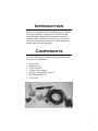
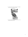
®
Sprayer Station
PRODUCT MANUAL
Item # 3349SS
Contents
Introduction
3
Components
3
Installing the Station
4
Installing SpecWare Mobile Software
13
Configuring the WatchDog Weather Station
14
Using the WatchDog Weather Station
20
Logging Weather and GPS Data
25
Log File Format
27
Troubleshooting
28
How the Sprayer Station Works
31
Specifications
35
Copyright 2008 Spectrum Technologies, Inc.
Updated Feb 19, 2008 for 2nd Generation Connector Box
2
Introduction
Thank you for purchasing the WatchDog Sprayer Station.
The Sprayer Station is designed to provide an accurate
indication and record of the environmental conditions
around a vehicle, whether it is stationary or in motion. It
allows for real-time measurement of weather data before,
during, and after a field operation.
Components
Your WatchDog Sprayer Station package should contain
the following components:
•
•
•
•
•
•
•
Sensor Unit
Mounting Post
Cable Assembly
Vehicle Power Adapter
Hook & Loop Fastener Strips (2)
SpecWare Mobile CD
User Guide
3
Installing
the Station
Caution: The blue metal plate and the blue film found in
the wind channel of the Sensor Unit are essential to its
operation. Be careful not to scratch the plate, puncture
the film, or damage them in any way.
Choosing the Mounting Location
The Sensor Unit must be mounted in “clear air”—away
from obstructions in any direction that will interfere with
air flowing through the unit. Ideally, this would be on the
roof of the cab or the tank. If the Sensor Unit is not the
highest point, be sure to mount it far enough from any obstruction so there is no interference with the air flow.
4
Because the Sensor Unit has an electronic compass, it
should be at least 3' (1 m) away from strong magnetic
fields from equipment such as radio transmitters. Since it
has a GPS, be sure it is as far as possible from highpowered transmitting antennas to avoid mutual interference. Similarly, mount the Sensor Unit far enough from
an existing GPS unit to avoid interference, and to keep the
Sensor Unit from blocking the GPS unit’s view of the sky.
The Sensor Unit must be installed vertically—NOT tilted
to one side. Tilting the unit will introduce an error in the
compass reading.
If you are using the magnetic mount, remember that you
must have a steel surface to attract the magnet. With a
fiberglass roof, this usually requires applying an adhesive
steel plate, as is used to provide a mounting point for GPS
units. The magnetic mount can also be removed, and a
standard ¼” bolt can be used to attach the mounting post
to the vehicle.
Once you have decided on a location, note which direction
you want the cable to travel. At this time, you may wish
to mark the front of the mounting post (the side which will
be pointing toward the front of the vehicle).
5
Assembling the Sensor Unit, Cable, and Mount
1. Gather the Sensor Unit, Mounting Post, and Cable Assembly.
2. With the nut assembly on the cable near the Sensor Unit
connector, slide the cable into the cable exit slot at the top
of the Mounting Tube. Leave several inches of cable
topped by the connector above the nut assembly.
3. Screw the nut assembly onto the top of the Mounting Tube.
Hand-tighten only. Do not over-tighten. Caution: If you
want to use a thread lock, use plumber’s tape. Do not use a
liquid thread lock as it may weaken the plastic, causing it to
swell and crack.
4. Remove the protective cover from the connector, and the
warning label from the bottom of the Sensor Unit. Plug the
7-pin connector into the Sensor Unit. The alignment key on
the connector fits into a notch in the base of the Sensor
Unit.
5. Be sure the alignment tabs on the Sensor Unit are facing
forward and parallel to the centerline of the vehicle. Remember to orient the front of the Mounting Post forward as
well, so the cable will exit in the correct direction. Slide
the captive nut upward and screw it onto the base of the
Sensor Unit. Hand-tighten only. Do not over-tighten. Be
6
careful NOT to rotate the Sensor Unit or loosen the nut assembly from the antenna mount/extension tube. Double
check to be sure the alignment tabs are still facing forward.
Alignment
Please note that for clarity the above diagram shows the sensor
alignment tabs and the cable exit both facing forward, it is uncommon for the cable to run forward from the sensor. It would
usually run to the rear or one of the sides, and the cable exit
should be aligned accordingly. The sensor itself must face for-
Temporary Mount
For temporary mounting of the Sprayer Station, slip the cable
through an open door or window. Caution: do not damage the
cable when closing the door or window. For doors, avoid the
area near the hinges as well as near the latch. Both areas exert
extremely high forces on the cable.
7
Permanent Mount
The Cable Assembly will have to be disassembled in order to
thread the cable through a hole in the wall or roof of the cab.
Although the cable will fit through a ¼” hole, a larger hole is
recommended to fit a grommet, to help ensure a watertight seal.
To disassemble the Cable Assembly:
There are two versions of the connector box on the end of the
cable. The first generation box is approximately the size and
shape of a deck of cards, and has a sliding “battery cover”. The
second generation box is smaller, and is labeled as “Item
#3349CB”.
1. Open the connector box, either by sliding the “battery
cover” to remove it (first generation),
or by inserting a screwdriver in the
slots on the side and twisting to separate the top and bottom halves (second
generation).
2. Using a small screwdriver (2 mm, 2.5
mm, or 1/10” blade – a small
“electronics” screwdriver has a 1/8”
blade which will not fit), loosen the
six screws, and remove the wires from
the terminal block.
3. Loosen the outer nut on the strain relief (first generation) or
cut the wire tie holding the cable (second generation), and
pull the cable out of the connector box.
8
To reassemble the Cable Assembly:
1. For a first generation box, thread the cable end through the
strain relief (it can help to remove the outer strain relief nut
completely, slipping it over the cable, and reattaching it
after the cable has been threaded through the strain relief).
2. Thread the six wires into the holes on the side of the terminal block, and tighten the screws to secure the wires. The
wire colors should be matched to the marked terminals as:
• TD(A) or TDA
Yellow
• TD(B) or TDB
Orange
• RD(A) or RDA
White
• RD(B) or RDB
Blue
• GND
Black
• +12VDC or +12
Red
3. Hand-Tighten the outer strain relief nut (first generation),
or secure the cable with a wire tie through the two holes on
the circuit board (second generation).
4. Slide the “battery cover” back onto the connector box (first
generation), or press the two case halves together, making
sure the LEDs are under the holes next to the label (second
generation).
First Generation Connector
Box - Terminal Block
top view
end view
Second Generation Connector Box Interior View (with Terminal Block)
9
Connecting to your PDA or Laptop
Connect your PDA cable to the 9 pin serial connector on the
connector box. If you are using a laptop or other PC, the power
cable will prevent a direct connection. You must use either a 9
pin M-F serial extension cable, or if your laptop does not have a
serial port, a USB to Serial converter cable (available from
Spectrum Technologies as Item # 3661USB).
If your cable has anchor screws, use them to hold the cable securely to the connector box. However, Murphy’s Law states
that it is more likely that your cable will have anchor nuts, as in
the photo below.
If you encounter this situation, perform the following steps to
connect your cable securely.
For a second generation connector box, use a wrench or pliers
to unscrew the anchor nuts. No disassembly is required.
For a first generation connector box:
1. With a Phillips screwdriver, remove
the four screws from the back of the
connector box.
2. Remove the back of the connector box.
3. Using a screwdriver and a pair of pliers, remove the two nuts from the
screws holding the 9 pin serial connector .
10
4. Attach your cable to the 9 pin serial connector, and tighten
the two screws to securely hold your cable.
5. Replace the back of the connector box, and secure it with
the four screws removed earlier.
11
In the Cab
Attach the Vehicle Power Cable to the connector box.
Determine a location for the PDA that will provide the
best visibility and access. Next decide where the connector box will be mounted, based on the length of the PDA
cable, and the distance to the nearest power outlet. Use
the provided Hook & Loop Fastener Strips to secure the
connector box and the PDA. Coil and secure any excess
cable.
12
Installing
SpecWare Mobile
Software
Insert the SpecWare Mobile installation CD in your computer’s disk drive. On most machines, the software installation will begin automatically. If it does not, run the
Setup.exe program on the CD. Follow the screen instructions to complete the installation. A desktop icon and a
Start menu entry will be created to run the PC version of
SpecWare Mobile.
Two additional menu items will be created. These will
prepare to install the the Pocket PC / Windows Mobile
2003 and the Windows Mobile 5 versions of SpecWare
Mobile for the PDA. Run whichever is appropriate for
your PDA (running the wrong install will not harm your
PDA; Windows will hold the install in anticipation of
your connecting a PDA running the other version). The
actual installation is done by ActiveSync. For those who
wish to customize the installation process, “cab” files are
placed in the SpecWare installation directory (this defaults
to “c:\SpecWare”, but can be overridden during the installation).
Once the SpecWare Mobile software is installed, you are
ready to begin using your Sprayer Station.
The current version of SpecWare Mobile software is
available on the Spectrum Technologies web site at
www.specmeters.com.
13
Configuring the
WatchDog
Sprayer Station
Connect your PDA or PC/laptop to the Sprayer Station
using the cable you attached to the Connector Box earlier.
Ensure that the Sprayer Station is receiving power (there
is a pilot light on the side of the Vehicle Power Cable; the
light should be lit).
Start SpecWare Mobile using the menu or icon. There are
minor differences between the PDA and PC versions of
SpecWare Mobile. These will be pointed out as appropriate in the following instructions. All images are from the
PDA version.
The first time you run SpecWare Mobile, the following
screen will be displayed.
14
The first step you must take is tell the PDA or PC where
to find the Sprayer Station. This is done by identifying
the communications (or “serial”) port the Station is
plugged into. For most PDAs, the serial port will be
“COM1”. For PDAs such as the iPaq, which do not have
a built-in serial port, a card can be added to provide a serial port. Documentation provided with these cards will
identify their port number.
If you are uncertain of the COM port on your PC, follow
the steps below.
1. If you are using a USB to Serial converter, plug it into
your PC.
2. From the Start menu, or on the Desktop, right-click
“My Computer”.
3. Select “Properties”.
4. Select the “Hardware” tab.
5. Select “Device Manager”.
6. Click on the “+” to the left of “Ports (COM & LPT)”.
A built-in serial port will be labeled “Communications
Port”. A USB converter will generally have “USB to Serial” in its name. In either case, the communications port
will be in parentheses, as in “(COM1)”.
Once you have identified the communications port you are
using, you must configure the station parameters in
SpecWare Mobile. Using your stylus, tap “Menu” in the
lower left corner. On a PC, click “Menu” in the upper left
corner. Your menu options are displayed on the next
page.
15
Tap (or click) on “Configure Station”. The following
16
On a PDA, a pull-down box will list the available communications ports. Select the one you are using. On a PC,
there is a text box to type in the number (without the
“COM”).
Next select the measurement system you wish to use.
English selects mph, degrees Fahrenheit, and in-Hg. Metric selects km/h or m/s, degrees Celsius, and hPa/mbar.
The Wind Alarm is set using the up/down arrows. “0”
indicates no alarm. For any other value, if the true wind
reaches or exceeds the Wind Alarm value, the wind speed
value on the main screen will have a bright yellow background (sound alarms are seldom loud enough on PDAs to
be heard over machinery).
Your Sprayer Station has been preset to send six specific
data messages to the PDA or PC. Under rare situations,
the Sprayer Station can “forget” those settings. The
“Reset Station” button is used to re-educate the Sprayer
Station.
Note: The communications ports on some PDAs were designed to omit key synchronization wires. The Sprayer
Station is so busy sending out weather data that it cannot
notice a message from the PDA or PC without those
wires. In this case, a PC would have to be used to reset
the Sprayer Station.
Tap “OK” to save your selections, and return to the main
screen.
Tap “Menu” again, and then tap “Configure Logging” to
set your data logging preferences.
17
Snapshots and data logs
can be stored in one of
three locations on a
PDA (these options are
omitted from the PC
version, as “My Documents” is the only
available option).
Choosing “My Documents” places the files in the samenamed folder in the main memory of the PDA. In Microsoft ActiveSync, checking “Files” on the “Tools / Options” screen will cause ActiveSync to copy all files to a
similarly named folder in “My Documents” on your PC.
Choosing “SD Card” places the files on an Secure Digital
memory card inserted into your PDA. The SD card can be
removed and placed in a flash card reader on your PC.
Windows Explorer can be used to move the files onto
your PC.
Similarly, choosing “CF Card” places the files on an
Compact Flash memory card inserted into your PDA. The
CF card can be removed and placed in a flash card reader
on your PC. Windows Explorer can be used to move the
files onto your PC.
Some PDAs have slots for both types of flash memory
18
cards, others support one type or the other. You can
change the location at any point in the future, but existing
files will not be automatically moved from the old to the
new location.
The WatchDog Sprayer Station can log location and
weather data continuously, at a specified interval. Logging is started and stopped via the “Log” button on the
main screen. If you want to disable logging, choose “No
Logging”. Otherwise select a data recording interval.
By default, all log records are written to a single file
named “Sprayer.Log.txt”. This is indicated by the “One
Log File” option.
“New Log File Each Day” places all log records in files
by day, named “Sprayer.Log.yyyymmdd.txt”.
“New File Each Log” creates a new file each time logging
is started using the “Log” button. The files are named
“Sprayer.Log.yyyymmdd.hhmm.txt”.
Checking “New Snapshot File Each Day” saves snapshots
in files named “Sprayer.Snap.yyyymmdd.txt” instead of
the default “Sprayer.Snap.txt”.
The “Log raw data” check box in the lower left corner will
activate logging of the actual weather data messages being
sent from the Sprayer Station. Most people will not want
to activate this option. It can fill all available memory in a
PDA in a short amount of time. It is provided for researchers who require the raw data, and for problem resolution.
Tap “OK” to save your selections, and return to the main
screen.
19
Using the WatchDog
Sprayer Station
Start SpecWare Mobile using the menu or icon. The “No
data” screen, below, will display until the program receives weather data from the Sprayer Station Sensor Unit.
If this does not occur within 10 seconds, please refer to
the “Troubleshooting” section of this manual.
Once enough data has been received, the display will
switch to the standard display view, as shown on Page 22.
20
The standard display view screen is updated once every 5
seconds, averaging the data received during that time.
The above image shows weather data without GPS information. This will be displayed until the GPS obtains a
position fix. The GPS time to first fix is one minute.
Note that a GPS fix will not be possible when there is not
a clear view of the sky, such as indoors, or in a heavily
forested location. The standard display view consists of
the following information:
Wind Direction
The wind direction is displayed in the upper left corner,
using eight compass points. If GPS data is available, the
true wind will be computed and displayed, otherwise the
apparent wind will be displayed, and the indicator
“(Apparent)” displayed below.
Apparent wind is the wind a person riding on the vehicle
would feel. True wind is the wind that would be measured if the vehicle were stationary. It is computed from
the apparent wind and the GPS-provided course and
speed.
Wind Speed
The wind speed is displayed in the upper right corner.
The units are as were specified in the Station Configuration. Either apparent or true wind speed will be displayed,
using the same rules as wind direction.
Wind Gust
The apparent or true wind gust is displayed on the first
text line.
Apparent Wind
The apparent wind direct, speed, and gust is displayed on
the second text line.
21
Weather Values
The current temperature, relative humidity, and barometric pressure are displayed on the third line. Relative humidity is displayed as a percent. Temperature is displayed
in degrees Fahrenheit or Celsius, and barometric pressure
in inches or millimeters of mercury, based on whether
English or Metric units were specified in the Station Configuration.
GPS Information
GPS information is displayed on the fourth line.
Satellites
The number of GPS satellites currently being received is
displayed as a number on the right side of the fourth line.
A GPS position fix is not obtained until at least three sat-
22
ellites are being received, and the more satellites, the more
accurate the position fix, and the computation of the vehicle and true wind speeds.
Monitor
On the far right of the fourth line is a small letter (a “W”
on the previous screen image). This letter should be frequently changing during normal operation. Each of the
six data messages sent by the Sprayer Station Sensor Unit
is assigned a letter which is displayed as it is received by
SpecWare Mobile. The data sentences are sent individually at one second intervals, and at times different letters
may be followed by a larger break, and therefore be easier
to see.
23
Control Buttons
The control buttons are large enough to be pressed by a
fingertip. The stylus should only be needed when configuring SpecWare Mobile.
View Button
Pressing the View button cycles between the standard display, a GPS-oriented display, and a record count display
(which is used for problem resolution).
Log Button
Pressing the Log button will start and stop the logging
function. The logging interval is set in the Logging Configuration. The log button will appear different when the
logging function is active.
SnapShot Button
The SnapShot button records a snapshot of the currently
displayed wind, weather, and GPS information.
Ok Button
The “ok” button in the upper right exits SpecWare Mobile
(Use the red “X” button for the PC version).
24
Logging Weather
and GPS Data
SpecWare Mobile stores logged data in one of three locations, as specified in the Logging Configuration. These
are “My Documents”, “SD Card”, and “CF Card”. See
the Configuration section for more details on these options.
Regardless of which location is specified, a folder will be
created with a name of “SprayerStation”. This folder will
contain the three types of log files. These files will be
added to until they are deleted or renamed, and then a new
file will be created.
Sprayer.Log.txt
When a log interval has been specified in Logging Configuration, and logging is activated using the Log button,
records are written to a “Sprayer.Log.txt” file. The file is
in text format, with tabs separating the values. This format can be easily imported into Excel (using the text import wizard) or other programs. The first record of the file
is a header record, identifying the columns.
By default, all log records are written to a single file
named “Sprayer.Log.txt”. This is indicated by the “One
Log File” option in “Configure Logging”. If you want to
have a separate file for each field application with full
control of the file names, stop SpecWare Mobile, and use
File (or Windows) Explorer to rename the file. Restarting
logging will create a new log file.
Alternatively, selecting “New Log File Each Day” in
“Configure Logging” places all log records in files by day,
25
named “Sprayer.Log.yyyymmdd.txt”.
Similarly, the “Configure Logging” option “New File
Each Log” creates a new file each time logging is started
using the “Log” button.
The files are named
“Sprayer.Log.yyyymmdd.hhmm.txt”.
Sprayer.Snap.txt
When the SnapShot button is pressed, a record is written
to the “Sprayer.Snap.txt” file. The format is the same as
the Log file.
Similar to the Log files, checking “New Snapshot File
Each Day” in “Configure Logging” saves any snapshots
in daily files named “Sprayer.Snap.yyyymmdd.txt”.
Sprayer.Raw.txt
If the “Log raw data” box is checked in “Configure Logging”, NMEA 0183 sentences from the Sensor Unit will
be written to the “Sprayer.Raw.txt” file. Most people will
not want to activate this option. It can fill all available
memory in a PDA in a short amount of time. It is provided for researchers who require the raw data, and for
problem resolution.
26
Log File Format
The Log and SnapShot files contain the following data
values, separated by tabs.
Date and Time
Temperature
Relative Humidity
Dew Point
Barometric Pressure
Apparent Wind Direction
Apparent Wind Speed
Apparent Wind Gust
If a GPS position fix is available, the records will also
contain:
True Wind Direction
True Wind Speed
True Wind Gust
Satellite Count
UTC
Latitude
Longitude
Course
Speed
27
Troubleshooting
If the station does not seem to be working at all
(the display shows “No data” unless the view is changed, or the
temperature, wind, etc., do not change from “0”):
1. Check that the pilot light is lit on the Power Adapter.
2. If you have a second generation connector box, confirm
3.
4.
5.
5.
28
that the “PWR” LED is lit.
Check that all connections are tight.
Verify that you are using the correct COM port for the station. If you are using a PDA, the most likely ports are
COM1 (for the built-in connector) or COM4 (for a CF serial card). If you are using PC with a USB-to-serial
adapter, and are uncertain of the COM port number, follow
the steps below.
• From the Start menu, select Control Panels.
• Select the System option.
• Select the Hardware tab.
• Select Device Manager.
• Select Ports.
• Look for a COM port which includes “USB” in its
name.
If you have a second generation connector box, ensure that
the “RX” light is blinking (this is the signal from the sensor
module). Otherwise, open the “battery cover” on the connector box and check the screw terminals with a voltmeter
to confirm that:
• “+12VDC” to “GND” is +12VDC (nominal).
• “RD(B)” to “RD(A)” cycles once per second between
+4.5VDC and 0VDC (this is the signal from the sensor
module).
For further investigation, reference the diagram on the next
page.
• If the prior checks show power, but not signal, remove
the sensor module from the cable and check that hole 1
(marked with a small dot) to hole 2 (clockwise next to
hole 1) reads +12VDC (nominal).
•
Disconnect the power cable from the connector box,
and use a continuity tester to check that all wires are
intact between the sensor module connector and the
screw terminals in the connector box.
If Step 4 above shows that signal is present, but it is not appearing on the PDA screen:
6. Use the PC program on a laptop to see if the problem is
with your PDA or cable.
7. Use Windows HyperTerminal on a laptop to eliminate Spec
Mobile as a problem:
IMPORTANT: Before starting HyperTerminal, note the
COM Port number that the Sprayer Station is connected to.
IMPORTANT: You must close Spec Mobile to use HyperTerminal with the Sprayer Station.
1. From the Start menu, select All Programs, Accessories,
Communications. Click HyperTerminal.
2. Enter an area code if prompted.
3. Select File, then New Connection.
4. Name the connection, then click OK.
5. Select the particular COM port that the Sprayer Station
is connected to, then click OK.
6. Set the bits-per-second to 4800. Do not change any
other selection. Click OK.
7. You should see the data sentences from the Sprayer
Station scrolling on the screen, similar to the following
example.
29
If a GPS position fix is not made after several minutes:
1. Ensure you are outdoors with a clear view of most of the
sky. Being able to see some sky through the trees is usually not enough.
2. Use menu option “View Station Counts”. All six record
types should have counts within one of each other. If one
or more types have counts of 0, or double the usual number,
then the Sensor Unit needs to be reset using the “Reset Station” button in Station Configuration.
If “Reset Station” doesn’t reset the station:
1. If you have a second generation connector box, watch the
“TX” LED after you click “Reset Station”. It should blink
about once per second as commands are sent to the station.
2. Some PDAs do not have the necessary wire connections to
get the attention of the Sensor Unit. Use the PC program
on a laptop instead.
30
How the Sprayer
Station Works
About the Ultrasonic Wind Sensor
The ultrasonic wind sensor (an ultrasonic anemometer) measures apparent wind speed and direction. The Sprayer Station contains four
ultrasonic transducers, visible through the four holes in the top of the
sensor’s wind channel. These transducers operate in pairs—one transducer injects a pulse into the air, and the other (directly opposite to it)
listens for the arrival of that pulse. Each pulse bounces off the metal
plate at the bottom of the wind channel and is carried by the wind to
arrive at the opposing transducer a short time later.
When there is no wind, the pulse travels at the speed of sound from
the sender to the receiver. Whenever the wind is blowing in that direction, the pulse will arrive sooner than if the air is still. Similarly,
whenever the wind is blowing in the opposite direction, the pulse will
arrive later than if the air is still. The four transducers take turns in
sending and receiving pulses to cover all possible wind directions.
A microprocessor within the Sprayer Station then combines the measurements from all four transducers to calculate the resultant wind
speed and direction. Throughout this process, the sensor monitors the
air temperature, to compensate for the fact that the speed of sound in
air changes with temperature.
Understanding True and Apparent Wind
The Sprayer Station has the unique ability to display both true and
apparent wind. True wind is the actual motion of the air relative to the
earth. Apparent wind is the wind which an observer experiences while
moving. It is the result of two motions—the actual motion of the air
(the true wind) and the motion of the vehicle. If the vehicle is not
moving, then the true and apparent wind will be the same.
There are two components to any wind measurement: speed and direction. By convention, the wind direction is an angle representing the
direction from which the wind is blowing.
31
Consider the case of a vehicle proceeding at a speed of 15 mph in
calm air. An observer on board would experience a wind of 15 mph
from dead ahead. This apparent wind would be due solely to the motion of the vehicle. If a true wind of 15 mph was blowing from the
rear, an observer would experience dead calm—no apparent wind.
That is because the vehicle is moving at the same speed and in the
same direction as the surrounding air.
Now, consider the more complicated situation of a vehicle proceeding
at 15 mph with a true wind of 15 mph blowing from the side. To an
observer on board, the apparent wind would be 21.2 mph blowing
from an angle 45º off the front.
In order to calculate the true wind speed and direction when on board
a moving vehicle, it is necessary to know the apparent wind speed and
direction, the speed and course over ground of the vehicle, the compass heading, and the local magnetic variation. Note that heading and
course are not the same thing: heading is the direction the vehicle is
pointing, while course is the direction the vehicle is traveling. On
land, heading and course differ only when the vehicle is stationary.
The Sprayer Station can provide true wind speed and direction only if
all of the data is available. The speed and course over ground must be
provided by a GPS receiver––either built-in or networked. The heading may be provided by either the built-in electronic compass or by an
external networked compass.
Because true wind is calculated using the data from several sensors,
its accuracy depends on the accuracy of all the raw data used in the
calculation. For instance, if the electronic compass is located near iron
or a similar magnetic disturbance, the heading will be incorrect, and
the true wind calculation will therefore be in error, perhaps by quite a
bit. In another example, the speed and course over ground (SOG and
COG) provided by the GPS receiver are averaged over time. If the
vehicle is performing maneuvers, changing speed and/or direction,
then it will take a few seconds for the SOG and COG values to "catch
up". The reported true wind values will therefore also be incorrect
until the vehicle reaches a steady-state condition, traveling in a
straight line at a constant speed.
About the Electronic Compass
The Sprayer Station includes a pair of magnetoinductive sensors that
measure magnetic field strength in two axes on the horizontal plane of
32
the Sprayer Station. From these measurements, it calculates the resultant magnetic heading angle, thereby providing a built-in electronic
compass.
Like all magnetic compasses, the Sprayer Station compass will be
affected by any ferrous or magnetic materials in the vicinity, such as
metal structures, motors, speakers, etc. It will also be affected by
nearby electric fields, such as the wiring for lights. These nearby
sources of magnetic interference will distort the magnetic field and
produce errors in the compass heading. These errors are known as
magnetic deviation.
Although the Sprayer Station compass is a 2-axis device, the earth's
magnetic field occurs in three dimensions. That is, part of the earth's
magnetic field is oriented in the vertical direction. The closer one's
location is to the north or south pole, the stronger this vertical component becomes in comparison to the horizontal components. The effect
this has on the Sprayer Station is to introduce an error in the compass
reading if the Sprayer Station is tilted from the horizontal plane.
Therefore, it is important when installing the Sprayer Station to ensure the support pole is mounted vertically, and not tilted to one side.
Also, keep in mind that when your vehicle experiences pitch and roll,
the compass heading will be affected accordingly.
Because the compass heading is used in the calculations for true wind,
any errors in the compass heading will also produce errors in the reported true wind speed and direction. This is adjusted for in the
Sprayer Station by using the GPS-sourced course over ground when
the vehicle is moving.
About Magnetic Variation and True Heading
The earth acts like a giant magnet, with a magnetic north pole and a
magnetic south pole. The axis of the magnetic poles is offset approximately 11.5° from the axis of the earth's rotation. Therefore, the
earth's magnetic north and south poles are in different locations than
the earth's geographic north and south poles. In addition, the earth's
magnetic field is non-uniform, and changes over time. Magnetic
variation, also known as magnetic declination, is the angle between
magnetic north and true (or geographic) north, at the observer's current location.
A magnetic compass measures heading with respect to magnetic
33
north. To convert this magnetic heading to true heading (that is, heading with respect to true north), the magnetic variation must be added
to the measured magnetic heading value.
Because magnetic variation changes with location and gradually over
time, it is necessary to calculate the magnetic variation using the
user's present position and the current date. Therefore it is necessary
to have a GPS with a fix in order to provide magnetic variation and
heading with respect to true north.
About the Air Temperature Sensor
The Sprayer Station includes a built-in negative-temperaturecoefficient thermistor that measures the ambient air temperature. This
NTC thermistor is located in a thermally isolated region of the
Sprayer Station housing that is open to the outside air.
About the Relative Humidity Sensor
The Sprayer Station contains a capacitive cell humidity sensor that
measures the relative humidity of the air. Humidity refers to the
amount of water vapor in the air. Relative humidity is the percentage
of saturation of the water vapor in the air. It is the ratio of the moisture content of the air to the saturated moisture level at the same temperature and pressure.
About the Barometric Pressure Sensor
The Sprayer Station contains a temperature-compensated, silicon,
piezoresistive, pressure sensor. It measures atmospheric pressure for
use as a digital barometer
About the GPS
The Sprayer Station has a built-in Global Positioning System with its
own antenna, receiver, and position determining electronics. The GPS
receiver receives radio signals from a constellation of orbiting satellites maintained by the U.S. government. By accurately measuring the
time it takes for a transmission to travel from each satellite to the receiver, the unit is able to determine the distance between the satellite
and the receiver. When the distance is known to three satellites, the
unit is able to calculate the latitude and longitude of the receiver. This
is known as a 2D (2 dimensional) fix. If the distance is known to four
34
or more satellites, then the unit is additionally able to calculate the
altitude of the receiver. This is known as a 3D, or 3 dimensional fix.
On average, the GPS receiver in the Sprayer Station takes approximately one minute to achieve a position fix after power is first applied. This is known as the "time to first fix." The GPS receiver has
16 channels to track satellites, and will use up to 12 satellites in computing a position fix.
The GPS receiver synchronizes itself to the atomic clocks on board
each satellite. This allows the GPS receiver to accurately determine
the date and time as well.
If the GPS receiver is mounted on a moving vehicle, its changing position over time allows the speed and course over ground to be calculated. The course reported by a GPS is always with respect to true
north.
The ability of the Sprayer Station to calculate true wind speed and
direction depends on the presence of a GPS fix. If the GPS receiver is
not tracking at least three satellites, then the Sprayer Station will be
unable to provide true wind data. (Apparent wind data should always
be available, regardless of the status of the GPS receiver.)
Specifications
Wind Speed Range
Wind Speed Resolution
Wind Speed Accuracy
Wind Direction Resolution
Wind Direction Sensitivity
Temperature Range
Temperature Accuracy
Compass Sensing
Barometric Pressure Range
Barometric Pressure Accuracy
Relative Humidity Range
Relative Humidity Accuracy
Supply Voltage
Supply Current
0.6 – 114 mph (1 to 185 km/h)
0.1 mph (0.2 km/h)
±1.1 mph (±1.9 km/h) or ±4%
1º
±1.5º
-22 – 122ºF (-30ºC – 50ºC) *
±2.7ºF (±1.5ºC) *
±1º typically
25 – 34 in-Hg (850 – 1150hPa)
±1.5%
10 – 95% RH
±5% RH *
10-16VDC (nominal 12VDC)
0.5 amp
* Note: The Sprayer Station’s accuracy can degrade below 32ºF (0º C).
Temperature and Humidity accuracy are with wind above 2.3 mph (3.7 km/h).
35
This equipment has been manufactured for
Spectrum Technologies Europe
The Manufacturer’s DECLARATION OF CONFORMITY is on file at the above
address, and certifies conformity to the following:
Model Number:
3349SS
Description:
WatchDog Sprayer Station
Directive:
EN 60945:1997-EMC Art 3.1b 00/05/CE
Maritime Navigation and Radiocommunication Equipment and Systems
Clauses:
9.2 Conducted Emissions
9.3 Radiated Emissions
10.2 Conducted Low Frequency Interference
10.3 Conducted Radio Frequency Interference
10.4 Radiated Interferences
10.5 Fast Transients of Signal and Control Lines
10.8 Immunity to Power Supply Failure
10.9 Immunity to Electrostatic Discharge
Warranty
This product is warranted to be free from defects in material
or workmanship for one year from the date of purchase. During the warranty period Spectrum will, at its option, either repair or replace products that prove to be defective. This warranty does not cover damage due to improper installation or use, lightning, negligence, accident, or
unauthorized modifications, or to incidental or consequential damages beyond the Spectrum product. Before returning a failed unit, you must obtain a Returned Materials Au-
36