1
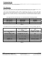
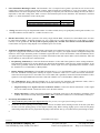
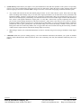
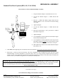
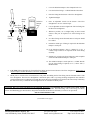
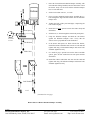
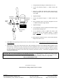
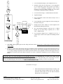
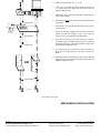
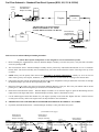
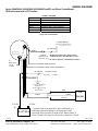
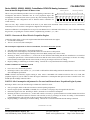
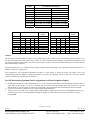
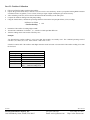
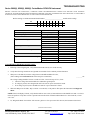
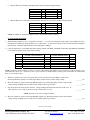
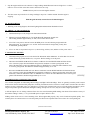
Installation / Troubleshooting Manual
Marine Cruisemaster Diesel, K Series,
Standard Flow, U.S & Metric
This manual (part # 4001-406-08) applies to the following product part numbers:
U.S.
1)
2)
3)
4)
5)
6)
7)
8)
9)
10)
11)
12)
13)
14)
15)
16)
17)
18)
19)
6310-201-2K
6310-BOS-2K
6320-201-2K
6320-231-2K
6320-BOS-2K
6305-201-2K
6505-201-2K
6505-BOS-2K
65080-2012K
6510-201-2K
6510-231-2K
6510-BOS-2K
6520-201-2K
6520-231-2K
6520-BOS-2K
6532-231-2K
6532-BOS-2K
6710-BOS-2K
6720-BOS-2K
METRIC
1) 63040-BOS2K
2) 63080-BOS2K
3) 65040-2012K
4) 65040-2312K
5) 65040-BOS2K
6) 65080-2012K
7) 65080-2312K
8) 65080-BOS2K
9) 65160-2312K
10) 65160-BOS2K
5/22/2007
FloScan Instrument Company, Inc.
3016 NE Blakeley Street, Seattle, WA 98105
4001-391-31
Tel: (206) 524-6625
Email: [email protected]
Fax: (206) 523-4961
Http://www.floscan.com
5/22/2007
FloScan Instrument Company, Inc.
3016 NE Blakeley Street, Seattle, WA 98105
4001-391-31
Tel: (206) 524-6625
Email: [email protected]
Fax: (206) 523-4961
Http://www.floscan.com
!
INSTALLATION PLANNING
!
READ ME FIRST - Detailed Mechanical & Electrical Planning Saves Installation Hours!
FloScan systems are not difficult to install. Installing one requires only basic electrical & mechanical skills. With forethought and
planning, your system will be installed with few problems. Todd Walker, Yacht Electric Co., (954) 325-9091 regularly installs
FloScan Twin Diesel Systems in 16 to 20 hours. Difficult installations take him about 24. Vessel owners installing a FloScan
Twin Diesel System for the first time may require an additional 4 to 10 hours.
I. Installation Preparation:
Review the pre-installation booklet and mechanical installation instructions, then survey your vessel. Determine where the
Sensor(s), Pulsation Damper(s), (If used) Switches and Instruments are to be mounted. Place them at their approximate locations.
Measure fuel line lengths between system components, (Primary Filter, Sensor(s), Damper(s), Engine, and Fuel Tank. Determine
fitting sizes and type of fittings needed for each plumbing connection, (JIC, SAE, NPT, NPTF, or Hose Barb).
FloScan Series K High Flow, Diesel system components have 1”, and ½” Female NPT ports.
FloScan Series K Standard Flow, Diesel, system components have ¼” Female NPT ports.
FloScan Gasoline High Flow, system components have ½” Female NPT ports.
FloScan Gasoline Standard Flow, system components have ¼” Female NPT ports.
Gasoline Fuel Systems: USCG requires Type A-1 Fuel Hose to be installed between the fuel tank and the engines’ fuel inlet
connection. Type B-1 may be used if certain safety requirements are met, (33 CFR, Subpart J, 183.558). 33 CFR Subpart J,
183.532 require hose clamps to be made from a corrosion resistant material. To meet American Boat & Yacht Council, (ABYC)
standards, the clamps must be made from a corrosion resistant metal, (ABYC, H-24.11.1).
Diesel Fuel Systems: Fuel hose and fittings comprise approximately 1/3 of the total installation cost. At $60/hr, labor costs for a
twin engine High Flow system installation will run approximately $960 to $1200. A-1 Fabric Braid hose & fittings will cost
approximately $600. A-1 Steel Braid hose & fittings would cost approximately $1700. Using wire braid reinforced fuel hose
increases twin engine installation costs by $700 to $1000. It pays to use Fabric Braided Hose, (Refer to Table II). Both
Type A-1 fabric braided and wire braided hose meet exactly the same regulatory requirements, (USCG & ABYC) but fabric braid
installation costs are far less. For more information contact Ed Sanford, FloScan’s Technical Service Manager at extension 302.
Fabric Braid A-1 fuel hose generally use hose barb fittings. These come in a wide range of Hose Barb to Male NPT, JIC, SAE, &
NPTF sizes and combinations. Example: 12 HB X 16 MNPT, (3/4” Hose Barb by 1” Male NPT).
Steel Braid, Aeroquip type A-1 fuel hose have reusable hose end fittings. Aeroquip type hose ends come in a wide variety of
types and sizes, (JIC, SAE, NPT, & NPTF).
Review the electrical installation instructions. Open and survey your vessels wire ways. Determine if it would be easier to run a
3-conductor cable from each sensor to the instrument, or install a junction box, (J-Box) with terminal strip in the engine room.
The J-Box requires a 4-conductor cable from it to the instrument, and a 3-conductor cable from each sensor. Measure cable
lengths from sensor(s) to J-Box, (If used) to Instrument. Tachometers require a separate 2-conductor cable. If there’s an existing
tachometer, its signal wires can be used.
Tools required are paper, pencil, and measuring tape. This should take no longer than 1-2 hours for both Diesel & Gasoline
systems.
II. Mechanical Installation:
Install or mount the Sensor/Pulsation Damper assemblies, or Sensors, Instruments and Switches, (Reset, MPG, Port/Starboard,
Synch).
Tools required are a drill motor, bits, hole saw, tape measure, straight edge, scribe/punch, half-round file, pliers, and combination
wrenches. This should take 1 hour for Gasoline and single Diesel systems, no more than 2 for twin Diesels.
5/14/2007
FloScan Instrument Company, Inc.
3016 NE Blakeley Street, Seattle, WA 98105
4001-386-00I
Tel: (206) 524-6625
Email: [email protected]
Fax: (206) 523-4961
Http://www.floscan.com
III. Plumbing:
Fabric Braid A-1 Fuel Hose: Install the correct HB X MNPT fitting into each fuel system component, Tank, Manifolds, Filter,
Sensor(s) Damper(s) and Engine. Assemble fittings using a fuel proof pipe thread sealant. Never use Teflon Tape. Referring to
the Fuel Flow Schematic, run the fuel hose between system components. Cut to correct length with a pocket or razor knife. Hoses
should not be twisted, have adequate slack, an ample radius at all bends and be supported at reasonable distances, approximately
2-4 feet. When clamping hose onto the barbs, use 2 narrow or 1 wide stainless hose clamp on each hose end.
Tools required are combination wrenches, screwdriver, knife, drill motor, bits, and punch. This should take approximately 1 to 2
hours on gasoline and single diesel systems, no more than 3 to 4 hours on twin diesel systems.
Wire Braid A-1 Aeroquip Type Fuel Hose: Install the correct fitting into each fuel system component, Tank, Manifolds, Filter,
Sensor(s) Damper(s) and Engine. Assemble fittings using a fuel proof pipe thread sealant. Never use Teflon Tape. Referring to
the Fuel Flow Schematic, run the fuel hose between system components. Cut to correct length and install hose ends.
•
•
If you choose to do this yourself, rent a hose-cutting tool and purchase a tube of assembly lubricant.
Most dealers will cut and assemble both hose ends for $10 per hose. Some charge as much as $40.
Hoses should not be twisted, have adequate slack, an ample radius at all bends and be adequately supported at reasonable
distances, approximately 2-4 feet. AP-50 copper sealing washers or Flaretite fitting seals may be required to seal JIC & SAE
fittings.
Tools required are combination wrenches, screwdriver, drill motor, bits, and punch. This will take approximately 4-6 hours on
single and twin Diesel systems.
IV. Electrical Installation:
Run cables between Sensor(s), J-Box, (If used) and Instrument(s). Cables must be adequately supported at reasonable distances,
approximately 2-4 feet.
Tools required are a screwdriver, diagonal pliers, and possibly a wire snake. This usually takes 1 to 2 hours. Difficult runs take
longer.
Wire Terminations—Referring to the wiring diagram. Connect Sensor, Instrument and Switches to their respective wires with
crimp type butt or ring connectors. Always cover connectors and wire ends with heat shrink tubing.
Tools required are a screwdriver, diagonal pliers, wire strippers, pliers, and heat gun. This usually takes 1 to 2 hours on Gasoline
systems, 2 to 4 hours on Diesels. Add an additional hour for confined workspaces.
Isolated Ground Electrical Systems: FloScan manufactures 12 VDC to 12 VDC, (PN 7000-097-00) and 24 VDC to 12 VDC,
(PN 7000-096-00) Isolated Ground Power Supplies / Voltage Reducers. These power supplies electrically isolate the FloScan
system from ship’s power and are used by the Washington State Ferry System and other large steel and aluminum vessel
operators. Additionally mounting sensors onto a non-conductive surface and using short lengths of non-metallic fabric braid fuel
hose to connect them further isolates the system.
Diesel Fuel is non-conductive but does contain a, “Static Electricity Dissipater” additive to minimize the risk of fuel tank fires
and explosions. Even with this additive, the electrical resistance of Diesel Fuel is extremely high and can be considered nonconductive. Installing the FloScan system with Isolated Ground power Supplies, Non-Conductive Sensor Mounting Surfaces and
Fabric Braid Fuel Hose will electrically isolate it from the vessel’s hull.
V. Pre-Startup:
• Always Prime the fuel system before Engine Start-Up. This prevents your engine from becoming air-bound.
If you have an electric priming or boost pump, circulate fuel for 10 minutes while checking for leaks. If the fuel system does not
have an electric priming pump, use the engine's manual pump. Before starting, slightly open or crack the lift pumps' outlet fitting.
Pump until all air is purged at the lift pumps' outlet. Before start-up, verify that all fuel system fittings are tight.
5/14/2007
FloScan Instrument Company, Inc.
3016 NE Blakeley Street, Seattle, WA 98105
4001-386-00I
Tel: (206) 524-6625
Email: [email protected]
Fax: (206) 523-4961
Http://www.floscan.com
VI. System Start-Up:
Start and run your engines. Look for leaks and other installation problems. If system is not operating properly refer to the
Troubleshooting Instructions and correct any deficiencies.
VII. Calibration:
When system is running properly, refer to the calibration instructions and calibrate your system. If installed properly, initial
calibration takes less than 1 hour. After consuming some fuel, final calibration should only take a few minutes.
• The US Code of Federal Regulations, (CFR’s) contain no requirement for using Type A-1, A-2, B-1 or B-2, USCG
approved fuel hose on diesel powered pleasure vessels. To meet ABYC standards though, fuel hose shall comply with the
requirements of UL 1114, Marine (USCG Type A) Flexible Fuel-Line Hose, or SAE J1527, Marine Fuel Hoses, (ABYC H33.6.1).
USCG approved fuel hose with either fabric or wire reinforcing braid meet the following standards:
Hose Marking
USCG Type A-1
USCG Type A-2
USCG Type B-1
USCG Type B-2
Permeation Rating
100g/m²/24hrs.
300g/m²/24hrs.
100g/m²/24hrs.
300g/m²/24hrs.
2½ Minute Fire Test
Required
Required
Not Required
Not Required
Table I
Cost comparison between steel & fabric braid A-1 fuel hose on a 50’ Diesel pleasure vessel with, “Stand-up” engine room,
48’, ¾” Hose / Engine x 2 =
96’
Hose End Fittings, 28 Ends.
Hose End Assembly Fee
Stainless Hose Clamps
Fittings 16 x 12
Fittings 12 x 12
Fittings 8 x 12
Aeroquip A-1 Steel Braid
Hose with JIC x MNPT
Fittings
$9.73 / Ft x 96’= $934.08
A-1 Fabric Braid Hose
with
HB x MNPT Fittings
$5.00/Ft x 96’= $480
$11.50 per End, x 28 = $322
$10 / Hose x 14 = $140
N/A
4ea x $13.80 = $55.20
20ea x $11.90 = $238
4ea x $10.75 = $43
N/A
N/A
28ea x $1.49 = 41.72
4ea x $5.39 = $21.56
20ea x $4.20 = $84
4ea x $3.59 = $14.36
Totals:
$1732.28
$641.64
Table II
5/14/2007
FloScan Instrument Company, Inc.
3016 NE Blakeley Street, Seattle, WA 98105
4001-386-00I
Tel: (206) 524-6625
Email: [email protected]
Fax: (206) 523-4961
Http://www.floscan.com
Installation Do’s & Don’ts
Do
Don’t
Always use a Fuel Proof Pipe Thread Sealant
when assembling fittings into fuel system
components, (Locktite PST, Rector Seal, or
equivalent).
Never use Teflon Tape!
If possible avoid using Push-Lok, Barb-Tite,
JIC or SAE swivel fittings. If used, always
install
Copper AP-50 sealing washers or Flaretite
fitting seals onto JIC and SAE swivel fittings.
Use thin wall, low pressure, full flow type
NPT or NPTF hose barb fittings.
Double clamp all hose barb fittings.
Minimize the use of 90º elbow fittings.
Install Sensors as far from the engine as practical.
Fuel must travel, “Up-hill” at least 1 or 2 inches
after leaving the Diesel Return Sensor, and all
Gasoline Sensors. Verify correct orientation and
fuel flow direction.
Avoid bolting or mounting
sensor(s) directly onto the engine.
Always install Diesel Forward Sensor/Pulsation
Damper assemblies and Gasoline Sensors in the
Fuel Pump’s Inlet or Vacuum line.
Limit Sensor/Pulsation Damper assembly
Operating Pressure to 20 PSI or Less.
Try to use A-1 Fabric Braid Fuel Hose.
If possible avoid using steel braid,
“Aeroquip” type hose, hard pipe or metal tube.
Always use 30-micron primary filters on Diesel
systems. 20 and 10-micron filters are also
acceptable if required by the engine manufacturer.
Avoid 2 or 5-micron primary filters.
Wire with Shielded Cable on Diesel installations.
If possible use a dedicated shielded wire pair for
Magnetic Pickup Tachometer Senders.
Never use unshielded wires on
Magnetic Pickup Tachometer Senders.
Connect all Negative wires to a Battery Minus
Buss or directly to the Battery’s Negative
Terminal.
Connect or, “Ground” wire shields / shield drains
to the engine block or vessel bonding system.
Never connect Negative, (Battery Minus) wires
to the Vessels Hull, Engine Block,
or other machinery.
On Instruments with a GPS interface, connect
FloScan’s Data (+) to the GPS signal output.
Connect Data (–) to a Battery Minus buss.
Do not connect FloScan’s Data (–)
to the GPS Data (–).
Always use non-illuminated switches for Totalizer
Reset, Port/Starboard Select, Hours/Synch, and
GPH/MPG.
Never use illuminated, or back-lit switches.
5/14/2007
FloScan Instrument Company, Inc.
3016 NE Blakeley Street, Seattle, WA 98105
4001-386-00I
Tel: (206) 524-6625
Email: [email protected]
Fax: (206) 523-4961
Http://www.floscan.com
INSTALLATION
MECHANICAL & WIRING OVERVIEW – Standard Flow (BOS, 201, 231, 235-2K)
To Ensure System Accuracy, Follow All Installation Instructions.
•
Sensor Placement. Determine where the Flow Sensor or Flow Sensor-Pulsation Damper assembly is to be installed. Install the
sensor or sensor-pulsation damper assembly so that the ports marked IN and OUT. All orientation arrows, (Ï) must be pointing
up. The forward sensor or forward sensor-pulsation damper assembly must be installed downstream of a Racor type primary
filter. Upon exiting the return sensor, fuel must travel “Up-Hill” on its way back to the fuel tank. The fuel return line, between the
return sensors’ outlet port and fuel tank should be no less than 12” and have a 1 to 2” upward rise. This keeps the return sensor
flooded improving accuracy. Place sensor assemblies in a protected location away from water spray.
Forward Sensor
And Pulsation
Damper Assembly
Return Sensor
And Pulsation
Damper Assembly
FloScan
FloScan
Outlet
Inlet
Outlet
Inlet
201/ 231-1K & 2K, 235-2K
201/ 231/ 235-2K
*Caution: Diesel System Components are not designed for use on Gasoline Fuel Systems.
•
Determine fitting type & size. Minimize the number of elbows and fittings. If swivel fittings are used, (JIC or SAE) their mating
surfaces must be sealed with FlareTite fitting seals. Fitting seals may be purchased through Fittings Inc. in Seattle, WA (206) 7674670, 1-800-552-0632, or a local hydraulic supply house.
(Continued on next page)
03/05/2008
FloScan Instrument Company, Inc.
3016 NE Blakeley Street, Seattle, WA 98105
4001-325-00H
Tel: (206) 524-6625
Email: [email protected]
Fax: (206) 523-4961
Http://www.floscan.com
•
Select Instrument Mounting Location. The instruments’ face is waterproof and a gasket is provided to seal its bezel to the
control panel. Choose a location away from the compass. Install 65/6600 series instruments 12” away from compass. Choose a
shaded location since direct sunlight may cause the LCD display to temporarily turn. This does not damage the LCD, but makes it
impossible to read until cooling down. Make a cutout in the instrument panel for the instrument. The instruments’ maximum
depth is 3 ½” minus the thickness of the console panel.
Instrument Series
6500/6600
7500/7600, 8500/8600, 9500/9600, TwinScan
•
Cutout Size
3 1/16”
3
3/8”
Wiring. Determine wiring run length and the number of switches needed, (always use good quality marine grade switches). Use
18 AWG conductors on runs under 50’. 16 AWG for runs over 50’.
•
Run & Connect Wires. Wire one system at a time. Always begin with the Black, “Ground” wires. Each Black sensor wire must
be connected to the Black, “Instrument Ground” wire. Use a single wire to connect these Black wires to the battery’s negative
terminal, or to the ground buss. For the system to operate properly the, “Ground” wires must be connected in this manner.
Connect other wires per the wiring diagram. Leave the RED, power wire for last.
•
Tachometer Installation Options. 75/7600, 85/8600, and 95/9600 series tachometers require one or two additional wires. If your
engine isn’t equipped with a tachometer sender, determine which type it requires, (AC Signal Generator or Magnetic Pickup) and
install one. Some engine alternators produce a tachometer signal and can be used as the tachometer sender. Mechanically driven
AC signal generators and magnetic pickups are available from FloScan and most marine dealers. Hewitt, Motorola, VDO and
Stewart Warner are some of the more common brands.
1.
Keep Existing Tachometer(s). Connect the FloScan tachometers’ Yellow and Violet signal wires to the existing tachometer.
If the tachometer sender wire(s) are not marked, trace them from the tachometer sender up to the existing tachometer. If one
sender lead is grounded, connect the FloScan tachometers Yellow signal wire to the ungrounded lead or terminal. Connect
the VIOLET wire to a Ground Buss, or Battery Minus.
2.
Replace Existing Tachometer(s). FloScan MFI instruments have a 3 3/8” outside diameter. This is a common size and fits
into most instrument mounting holes. Identify the engines’ tachometer sender wires. Connect the FloScan tachometers’
Yellow and Violet signal wires to the sender wires. If one sender lead is grounded, connect the FloScan tachometers Yellow
signal wire to the ungrounded lead or terminal. Connect the VIOLET wire to a Ground Buss, or Battery Minus.
3. New Tachometer(s). Run a dedicated shielded pair of wires between the instrument and tachometer sender, (This is
especially important with Magnetic Pickup senders). Ground the shield only in the engine room.
•
•
Magnetic Pickup & AC Signal Generator Tachometer Senders: Connect the FloScan tachometers’ Yellow signal
wire to one sender terminal. Connect the Violet wire to the other terminal.
•
Engine Alternators: Connect the FloScan tachometer’s YELLOW signal wire to the alternator’s tachometer output
terminal. This terminal is usually marked as TACH, or SIG. Connect the VIOLET wire to a Ground Buss, or Battery (-).
Pre-Startup & Installation Check.
• Always Prime the fuel system before Engine Start-Up. This prevents your engine from becoming air-bound.
•
•
If you have an electric priming or boost pump, circulate fuel for 10 minutes while checking for leaks. If the fuel system does
not have an electric priming pump, use the engine's manual pump. Before starting, slightly open or crack the lift pumps'
outlet fitting. Pump until all air is purged at the lift pumps' outlet. Before start-up, verify that all fuel system fittings are tight.
(Continued on next page)
03/05/2008
FloScan Instrument Company, Inc.
3016 NE Blakeley Street, Seattle, WA 98105
4001-325-00H
Tel: (206) 524-6625
Email: [email protected]
Fax: (206) 523-4961
Http://www.floscan.com
•
•
System Start-Up. Start and run your engines. Survey the installation for leaks and other problems. If the system is not operating
properly refer to the Troubleshooting Instructions and correct any deficiencies. When the engine reaches operating temperature
increase engine speed to about 1500-2000 RPM. Letting it run for five or ten minute’s helps purge residual air from the system.
•
Any vacuum leaks between the fuel tank and lift pump will allow air to be drawn into the system. These leaks cause high
and/or fluctuating GPH readings. Only severe leaks affect engine performance, but all leaks affect sensor performance and
instrument readings. Vacuum or suction leaks occur at improperly sealed primary filters, loose packing nuts on cross over &
shut off valves and improperly sealed fittings. Vacuum leaks can also occur from corroded copper fuel lines and chaffed fuel
hose, (where it rubs against bulkheads or engine parts). To verify that a suction leak is present, temporarily insert a clear
piece of fuel resistant tubing downstream of the Forward Sensors’ outlet. Observe the clear hose for at least two minutes
looking for bubbles. Bubbles can appear as a constant stream of small bubbles, or as an occasional larger bubble. Tighten all
possible leak sources, grease primary filter seals and install fitting seals on JIC/SAE fittings. Continue to observe the clear
tubing until it runs clear without any bubbles. Flex or wiggle rubber hose sections while observing the clear tubing. If bubble
volume increases inspect the hose and check its fittings. Repair as necessary.
•
When idling in neutral, (No Load) GPH fluctuations can also be caused by the governor trying to maintain a steady engine
RPM.
Calibration. When the system is running properly, refer to the calibration instructions and calibrate your system. If installed
properly, initial calibration takes much less than one hour. After consuming some fuel, final calibration should only take a few
minutes.
03/05/2008
FloScan Instrument Company, Inc.
3016 NE Blakeley Street, Seattle, WA 98105
4001-325-00H
Tel: (206) 524-6625
Email: [email protected]
Fax: (206) 523-4961
Http://www.floscan.com
03/05/2008
FloScan Instrument Company, Inc.
3016 NE Blakeley Street, Seattle, WA 98105
4001-325-00H
Tel: (206) 524-6625
Email: [email protected]
Fax: (206) 523-4961
Http://www.floscan.com
MECHANICAL ASSEMBLY
Standard Flow Diesel Systems (BOS, 201, 231 & 235-2K)
Forward Sensor to Forward Pulsation Damper Assembly
Sensor
Body
FloScan
Hex Flow
Straightener
VISE
Hex Reducer
Nipple
Pulsation
Damper
Base
1.
Clamp the Pulsation Damper’s aluminum base into a vise.
2.
Coat the Hex Reducer Nipple’s ½” MNPT threads with
sealant.
3.
Place the ½” MNPT Hex Reducer Nipple threads into the
Pulsation Damper’s base end with the Inward Pointing
Arrow (Î).
4.
Tighten hand tight.
5.
Coat the Hex Reducer Nipple’s ¼” MNPT threads with
sealant.
6.
Place the Forward Sensor’s “OUT” port onto the ¼”MNPT
Hex Reducer Nipple end.
7.
Tighten hand tight.
8.
Use an adjustable wrench to tighten the Hex Reducer Nipple
into the Pulsation Damper base.
9.
Use an adjustable wrench to tighten the sensor body onto the
Hex Reducer Nipple. DO NOT put a wrench on the Forward
Sensor’s Hex Flow Straightener, at the Sensor’s inlet port
10. When tightened, the Sensor’s base and the Pulsation Damper
base must be even.
•
CAUTION: When tightening the Forward Sensor onto the Hex Reducer, always place the wrench onto the Sensor’s body.
•
Never place a wrench on the Forward Sensor’s Hex Flow Straightener while assembling the Sensor onto the Forward
Pulsation Damper. The Flow Straightener is locked into place with a very strong retaining compound and must remain in
position. It must not be tightened or loosened. Moving the Flow Straightener in relation to the Sensor body will destroy the
Sensors accuracy. Turned Flow Straighteners are not considered warranty items.
CAUTION, DO NOT OVER TIGHTEN FLOW SENSOR FITTINGS. Over-tightening may crack the sensor’s body. Cracks
cause leaks, and fuel leaks sometimes cause catastrophic explosions and fire. Assemble fittings with a Lubricating, Fuel Proof,
Non or Semi Hardening pipe thread sealant, designed for aluminum and stainless steel threads, (Loctite 567 or equivalent).
DO NOT USE TEFLON TAPE.
(Continued on next page)
Forward Fuel Line Fitting to Forward Sensor Assembly
07/24/08
FloScan Instrument Company, Inc.
3016 NE Blakeley Street, Seattle, WA 98105
4001-443-00
Tel: (206) 524-6625
Email: [email protected]
Fax: (206) 523-4961
Http://www.floscan.com
Sensor
Body
FloScan
Hex Flow
Straightener
VISE
Fuel Line
Fitting
Pulsation
Damper
Base
1.
Leave the Pulsation Damper’s base clamped in the vise.
2.
Coat the fuel line fitting’s ¼” MNPT threads with sealant.
3.
Place the fitting into the Sensor’s Hex Flow Straightener.
4.
Tighten hand tight.
5.
Place an adjustable wrench on the Sensor’s Hex Flow
Straightener to act as a counter torque.
6.
Use an adjustable wrench to tighten the fuel line fitting into
the Hex Flow Straightener.
7.
Whenever possible, use a straight fitting on the Forward
Sensor’s inlet port. If required a 45° elbow fitting can be
used.
8.
90° elbow fittings on the Forward Sensor’s inlet port should
be avoided.
9.
Determine which type of fitting is required for the Pulsation
Damper’s outlet port.
10. If the Pulsation Damper’s base is clamped in a vise, a
counter torque wrench is not required for the outlet fitting
assembly.
11. Straight, 45° or single 90° elbow fittings are each acceptable
at the forward Pulsation Damper’s outlet port.
12. The Pulsation Damper’s outlet port has ½” FMPT threads.
If a 90° elbow fitting is required, use a ½” elbow with ½”
MNPT threads.
•
CAUTION: When tightening the forward fuel line fitting into the Forward Sensor’s Hex Flow Straightener, always place a
counter torque wrench on the Sensor’s Hex Flow Straightener.
•
Never place a wrench on the Forward Sensor’s body while assembling the fuel line fitting into the Forward Sensor’s Hex
Flow Straightener. The Hex Flow Straightener is locked into place with a very strong retaining compound. It must remain in
position and must not be tightened or loosened. Moving the Hex Flow Straightener in relation to the Sensor body will destroy
the Sensors accuracy. Turned Hex Flow Straighteners are not considered warranty items.
CAUTION, DO NOT OVER TIGHTEN FLOW SENSOR FITTINGS. Over-tightening may crack the sensor’s body. Cracks
cause leaks, and fuel leaks sometimes cause catastrophic explosions and fire. Assemble fittings with a Lubricating, Fuel Proof,
Non or Semi Hardening pipe thread sealant, designed for aluminum and stainless steel threads, (Loctite 567 or equivalent).
DO NOT USE TEFLON TAPE.
(Continued on next page)
07/24/08
FloScan Instrument Company, Inc.
3016 NE Blakeley Street, Seattle, WA 98105
4001-443-00
Tel: (206) 524-6625
Email: [email protected]
Fax: (206) 523-4961
Http://www.floscan.com
1.
Place the Forward Sensor-Pulsation Damper assembly, with
inlet and outlet fittings installed, onto the flat bracket. Orient
the Sensor body over the slots and the Pulsation Damper
base over the bolt holes.
2.
Slide a lock washer onto two, 1¼” bolts.
3.
Chose your 90° mounting bracket option. Assemble the 1¼”
bolts through the angle and flat brackets into the Pulsation
Damper base.
4.
Tighten the bolts a little past hand tight, compressing the
lock washers slightly.
5.
Install the two short spacers between the Sensor body and
flat bracket.
6.
Slide the two, 2” bolts through the Sensor body and spacers.
7.
Grasp the Pulsation Damper and hold the flat bracket
against the Pulsation Damper’s base. Verify that the
Sensor’s base is perpendicular to the flat bracket.
8.
If the Sensor and spacers are flush with the flat bracket,
install flat washers and ESNA nuts onto the 2” bolt ends and
tighten until snug. The Pulsation Damper and sensor bolts
should be tightened evenly.
9.
If a small air gap is present between the Sensor and both
spacers, place one flat washer between each spacer and the
flat bracket.
FloScan
2"
Short Spacers
Additional
Flat Washers
If Needed
Flat Washers
ESNA Nuts
10. Install flat washers and ESNA nuts onto the bolt ends and
tighten until snug. The Pulsation Damper and Sensor bolts
should be tightened evenly.
OR
Lock Washers
1-1/4"
(Continued on next page)
Return Sensor to Return Pulsation Damper Assembly
07/24/08
FloScan Instrument Company, Inc.
3016 NE Blakeley Street, Seattle, WA 98105
4001-443-00
Tel: (206) 524-6625
Email: [email protected]
Fax: (206) 523-4961
Http://www.floscan.com
Hex Flow
Straightener
FloScan
Sensor
Body
VISE
Hex Reducer
Nipple
Pulsation
Damper
Base
1.
Clamp the Pulsation Damper’s aluminum base in a vise.
2.
Coat the Hex Reducer Nipple’s ½” MNPT threads with
sealant.
3.
Place the ½” MNPT Hex Reducer Nipple threads into the
Pulsation Damper’s base end with the Outward Pointing
Arrow, (Í).
4.
Tighten hand tight.
5.
Coat the Hex Reducer Nipple’s ¼” MNPT threads with
sealant.
6.
Place the Return Sensor’s Hex Flow Straightener onto the
¼” MNPT Hex Reducer Nipple threads.
7.
Tighten hand tight.
8.
Use an adjustable wrench to tighten the Hex Reducer Nipple
into the Pulsation Damper base.
9.
Use an adjustable wrench to tighten the Sensor’s Hex
Straightener onto the Hex Reducer Nipple’s ¼” MNPT
threads. DO NOT put a wrench on the Return Sensor’s
body.
10. When tightened, the Return Sensor’s body and the Pulsation
Damper base must be even.
•
CAUTION: When tightening the Return Sensor onto the Hex Reducer Nipple, always place the wrench on the Sensor’s Hex
Flow Straighterer.
•
Never place a wrench on the Return Sensors body while assembling the Sensor onto the Return Pulsation Damper. If the
Return Sensor is tightened at its body, the Sensors Hex Flow Straightener may be moved. The Flow Straightener is locked
into place with a very strong retaining compound and must remain in position. It must not be tightened or loosened. Moving
the Flow Straightener in relation to the sensor body will destroy the Sensors accuracy. Turned Flow Straighteners are not
considered warranty items.
CAUTION, DO NOT OVER TIGHTEN FLOW SENSOR FITTINGS. Over-tightening may crack the sensor’s body. Cracks
cause leaks, and fuel leaks sometimes cause catastrophic explosions and fire. Assemble fittings with a Lubricating, Fuel Proof,
Non or Semi Hardening pipe thread sealant, designed for aluminum and stainless steel threads, (Loctite 567 or equivalent).
DO NOT USE TEFLON TAPE.
(Continued on next page)
Return Fuel Line Fitting to Return Sensor Assembly
03/11/2008
FloScan Instrument Company, Inc.
3016 NE Blakeley Street, Seattle, WA 98105
4001-443-00
Tel: (206) 524-6625
Email: [email protected]
Fax: (206) 523-4961
Http://www.floscan.com
Straight
Fitting
45-Degree
Elbow Fitting
90-Degree
Fitting
Sensor
Body
Hex Flow
Straightener FloScan
1.
Leave the Pulsation Damper’s base clamped in the vise.
2.
Determine which fuel line fitting type is most appropriate
for your application, (please refer to steps 8-12 on pages 7
and 8 in the Mechanical Installation section of this
document). Any type of fitting, (straight, 45°, or 90° elbow)
is acceptable on the Return Sensor’s outlet port.
3.
Coat the fuel line fitting’s ¼” MNPT threads with sealant.
4.
Tighten hand tight.
5.
Place an adjustable wrench on the Sensors body to act as a
counter torque.
6.
Use an adjustable wrench to tighten the fuel line fitting into
the Sensors outlet port.
Pulsation
Damper 7.
Base
Straight, and 45° elbow fittings are each acceptable at the
Return Pulsation Dampers inlet port
8.
The return Pulsation Damper’s inlet port has ½” FMPT
threads. If a 90° elbow fitting is required, use a ½” elbow
with ½” MNPT threads.
9.
If the pulsation damper base is clamped in the vise, a
counter torque wrench is not required for installing the inlet
fitting.
VISE
Fuel Line Fittings
•
CAUTION: When tightening the fuel line fitting into Return Sensor, always place a counter torque wrench on the Return
Sensor’s Body.
•
Never put a wrench on the Return Sensors Hex Flow Straightener while assembling the fuel line fitting into Return Sensor. If
the Return Sensor is held at the Hex Flow Straightener it may be moved. The Hex Flow Straightener is locked into place with
a very strong retaining compound. It must remain in position and must not be tightened or loosened. Moving the Hex Flow
Straightener in relation to the Sensor body will destroy its accuracy. Turned Flow Straighteners are not considered warranty
items.
CAUTION, DO NOT OVER TIGHTEN FLOW SENSOR FITTINGS. Over-tightening may crack the sensor’s body. Cracks
cause leaks, and fuel leaks sometimes cause catastrophic explosions and fire. Assemble fittings with a Lubricating, Fuel Proof,
Non or Semi Hardening pipe thread sealant, designed for aluminum and stainless steel threads, (Loctite 567 or equivalent).
DO NOT USE TEFLON TAPE.
(Continued on next page)
1.
Place the Return Sensor-Pulsation Damper assembly, with
inlet and outlet fittings installed, onto the flat bracket.
Orient the Sensor body over the slots and the Pulsation
Damper base over the bolt holes.
07/24/08
FloScan Instrument Company, Inc.
3016 NE Blakeley Street, Seattle, WA 98105
4001-443-00
Tel: (206) 524-6625
Email: [email protected]
Fax: (206) 523-4961
Http://www.floscan.com
2-1/4"
FloScan
2.
Slide a lock washer onto two, 1¼” bolts.
3.
Chose your 90° mounting bracket option. Assemble the
1¼” bolts through the angle and flat brackets into the
Pulsation Damper base.
4.
Tighten the bolts a little past hand tight, compressing the
lock washers slightly.
5.
Install the two long spacers between the Sensor body and
flat bracket.
6.
Slide the two, 2¼” bolts through the Sensor body, spacers
and flat bracket.
7.
Grasp the Pulsation Damper and hold the flat bracket
against the Pulsation Damper’s base. Verify that the
Sensor’s base is perpendicular to the flat bracket.
8.
If the Sensor and spacers are flush with the flat bracket,
install flat washers and ESNA nuts onto the 2¼” bolt ends
and tighten until snug. The Pulsation Damper and Sensor
bolts should be tightened evenly.
9.
If a small air gap is present between Sensor and spacers,
place one flat washer between each spacer and the flat
bracket.
Long Spacers
Additional
Flat Washers
If Needed
Flat Washers
ESNA Nuts
OR
10. Install flat washers and ESNA nuts onto the bolt ends and
tighten until snug. The Pulsation Damper and Sensor bolts
should be tightened evenly.
Lock Washers
1-1/4"
(Continued on next page)
MECHANICAL INSTALLATION
07/24/08
FloScan Instrument Company, Inc.
3016 NE Blakeley Street, Seattle, WA 98105
4001-443-00
Tel: (206) 524-6625
Email: [email protected]
Fax: (206) 523-4961
Http://www.floscan.com
Fuel Flow Schematic - Standard Flow Diesel Systems (BOS, 201, 231 & 235-2K)
Primary
Filter
Forward Sensor
And Pulsation
Damper Assembly
FloScan
Return Fuel
Cooler
Engine
THE RETURN FLOW SENSOR MUST
REMAIN FLOODED AT ALL TIMES.
PLEASE REFER TO STEPS 9-12 BELOW.
Tank
Return Sensor
And Pulsation
Damper Assembly
FloScan
Fuel Flow Direction
FloScan Sensor & Pulsation Damper Plumbing Guidelines:
1.
*Caution: Diesel System Components are not designed for use on Gasoline Fuel Systems.
Before installing the assembled Flow Sensor & Pulsation Damper assembly’s into the fuel system, verify that their orientation
arrows are pointing UP Ï.
2.
The Forward Flow Sensor / Pulsation Damper assembly must be protected by and installed downstream of a 10 to 30 Micron
Primary Filter. The forward assembly can be installed at any convenient location from the bottom of the bilge to the top of the
overhead.
3.
NOTE: Always use the primary filter micron rating Specified by the Engine Manufacturer, (usually 10, 20 or 30). Do not
follow advice given by local experts, mechanics, or magazines. There are several reasons for avoiding 2 and 5 micron filters.
4.
Filtered fuel must enter into the Forward Sensor through its Hex Flow Straightener on the port marked IN. Fuel must exit through
the Pulsation Damper port with an outward pointing arrow, (Î).
5.
Return fuel from the engine, must enter into the Return Pulsation Damper’s inlet port. This is the port marked with an inward
pointing arrow, (Í) and exit through the port marked OUT on the Return Sensor.
6.
Install the Forward & Return Sensor – Pulsation Damper assemblies as far from the engine as practical. Maximizing fuel line
length, between the engine and Sensor – Pulsation Damper assembly, improves instrument accuracy.
7.
Use the smallest approved fuel line diameter for your engine, especially on the return line. Higher fuel flow velocities increase
overall system accuracy. Refer to the engine owners or shop manual for more information.
8.
IMPORTANT NOTE: THE RETURN FLOW SENSOR MUST REMAIN FLOODED AT ALL TIMES.
9.
If possible, install the Return Sensor – Pulsation Damper assembly at a low point in the fuel system.
(Continued on next page)
Return Sensor
And Pulsation
Damper Assembly
Return Sensor
And Pulsation
Damper Assembly
07/24/08
FloScan Instrument
Company, Inc.
Straight
45-Degree
FloScan
Fitting
3016 NE Blakeley
Street,
Seattle, WA 98105Elbow Fitting
3/8" JIC
Tube Assembly
(PART #231-058-00)
524-6625
Tel: (206)
Email: [email protected]
FloScan
Return Sensor
And Pulsation
Damper Assembly
4001-443-00
Fax: (206) 523-4961
Http://www.floscan.com
FloScan
10. There must be some vertical rise to the return fuel flow upon exiting the Return Sensor. There should be a minimum, “Up-Hill”
climb of 1 or 2 inches. Higher rises up to 3 feet or a little more are ok.
11. If installing the Return Sensor-Pulsation Damper as outlined in step 9 is not practical, please refer to steps 12 and 13 below.
12. If the return line is fairly horizontal but with a small, “Down-Hill” drop after exiting the sensor, install an upward pointing 45°
elbow into the return sensors outlet port. Install the fuel line with a downward radius bend. Do not pinch the hose.
13. If there is a steep vertical drop in the return fuel line, a tube with a 180° radius bend may be the best option. This option requires:
•
•
•
One, 90° male elbow with one male JIC 37° 3/8” or Dash 6 (–6) end, and one 1/4" male NPT end.
Two, Dash 6 (–6), (3/8) FlareTite fitting seals, www.flaretite.com, (to be installed onto the male JIC fitting ends).
One, Dash 6 (–6), (3/8) JIC tube assembly.
The tube assembly, P/N 231-058-00 can be purchased directly from FloScan Technical Support. The 90° NMPT x JIC elbow fitting,
and the FlareTite fitting seals can be purchased at most hydraulic shops.
14. Flow sensor model numbers are molded into the colored plastic wire cap. Sensors are shipped in matched pairs. They must not be
mixed on twin engine installations. Match codes are identified by a single stand-alone letter stamped into the sensor body, or from
a colored sticker on the sensors body.
15. Model *235 sensors are temperature compensated and stamped with their instruments serial number, xxxxF (Forward), xxxxR
(Return). *235-2K Temp-Comp sensor kits are precisely calibrated and matched to each instrument. Sensors are labeled
FORWARD and RETURN and must be installed in these positions for proper operation. The instrument head serial number must
match the flow sensor(s) serial number.
16. If there’s a shut-off valve in the return line, do not operate the engine with it closed. Fuel system pressure could exceed the
maximum system working pressure of 40 PSI and may cause a catastrophic system failure. You should either tag the valve so the
engine will not run when it is closed for maintenance, or bypass it with a relief valve.
NOTE: Minimize the number of 90º elbows and pipe fittings on the sensor or pulsation dampers inlet port. Excessive use may
create a high vacuum, fuel restricting, pressure drop across the forward part of the fuel system. Refer to the engine owners’
manual for maximum fuel pump inlet vacuum. A vacuum gauge can be used to confirm that the system is within limits.
CAUTION, DO NOT OVER TIGHTEN FITTINGS. Over-tightening may crack the sensor’s body or pulsation damper’s
base. Cracks cause leaks, and fuel leaks sometimes cause catastrophic explosions and fire. Assemble fittings with a Lubricating,
Fuel Proof, Non or Semi Hardening pipe thread sealant designed for aluminum and stainless steel threads, (Loctite 567 or equivalent).
DO NOT USE TEFLON TAPE.
07/24/08
FloScan Instrument Company, Inc.
3016 NE Blakeley Street, Seattle, WA 98105
4001-443-00
Tel: (206) 524-6625
Email: [email protected]
Fax: (206) 523-4961
Http://www.floscan.com
ELECTRICAL
Series 5400(0)/5500(0)/56100/5800(0)/6500(0)/6600(0) AccuTroll & CruiseMaster,
All Multi Function Instruments, & TwinScan®
SET UP
Wire & Switches: Use 18 AWG stranded wire on runs under 50’. For runs over 50’ use 16 AWG. Shielded wire is recommended
for all Diesel systems and suggested for Inboard & I/O gasoline systems. Always, “Ground” the wire shield or shield drain wires in
the engine room by connecting them to the bonding system or engine block. The double wiring harness for twin engine
Pulse/NMEA Diesel installations is included in all, (97/9800(0)) kits. FloScan suggests using J-Boxes, Terminal Blocks, and three
conductor cables between diesel sensors and instrument to make wiring easier.
Install Single Pole Single Throw (SPST) switches for Totalizer Reset, Port–Starboard Select, Engine Hours / Synchronizer, and
GPH / MPG, (switches are not included with kit). To determine which switch types are required for your system, refer to the table
below. All instruments except TwinScan Tachometers require a totalizer reset switch.
SYSTEM
5400(0)
5500(0)/56100
5800(0)
6500(0)/6600(0)
65/6600(0) Cummins PT
7000/8000(0) Gasoline MFI
71/8A00(0) MFI - Gasoline
EFI
75/7600(0) Diesel MFI
9000 Gasoline MFI
9A00(0) MFI - Gasoline EFI
95/96/97/9800(0)
TwinScan GPH Meter
TwinScan Tachometer
TwinScan GPH & Tachometer
NA = Not Applicable
SPST or Momentary OFF
SPST or Momentary OFF
SPST or Momentary OFF
SPST or Momentary OFF
SPST or Momentary OFF
SPST or Momentary ON
PORT/STBD
Twin Engine Systems
SPST
SPST
NA
NA
SPST
SPST
HOURS/
SYNCH
NA
NA
NA
NA
NA
SPST
SPST or Momentary ON
NA
NA
NA
NA
SPST or Momentary ON
SPST or Momentary ON
SPST or Momentary ON
SPST or Momentary ON
SPST or Momentary ON
NA
SPST or Momentary ON
NA
SPST
NA
NA
NA
NA
NA
NA
SPST
NA
NA
NA
NA
NA
NA
SPST
SPST
SPST
NA
NA
NA
NA
NA
NA
NA
NA
NA
SPST
TOTALIZER RESET
GPH/
MPG
NA
NA
NA
NA
NA
NA
MPG/
SYNCH
NA
NA
NA
NA
NA
NA
Grounding: Each Black sensor wire must be connected directly to the Black, “Instrument Ground” wire. Use a single wire to
connect the Black wire junction to the battery’s negative terminal, or a ground buss.
Power: FloScan Instruments & sensors operate on 9 to 12 VDC. Voltages exceeding 16 VDC will damage equipment. 24 & 32
VDC systems must be reduced to 12 VDC. Two different types of voltage reducers are available through FloScan.
WIRE CONNECTIONS
Installation: Connect wires one at a time and install heat shrink tubing
before proceeding to the next wire, (refer to diagram). Connect ground
wires first, (BLACK instrument ground wire to the BLACK sensor
wires). Connect this junction to the battery’s negative terminal or the
ground buss. Connect all other wires leaving the Red power wires for
last to prevent short circuits during installation.
Splicing: Splice or join individual wires per the diagram. Slide heat
shrink tubing over the splices to prevent shorts. Do not seal splices until
the installation is finished and has been tested.
5/25/2006
FloScan Instrument Company, Inc.
3016 NE Blakeley Street, Seattle, WA 98105
1. Slide heat shrink tubing
over one wire.
2. Insert wire ends into butt splice.
3. Crimp butt splice.
4. Slide heat shrink tubing
over butt splice.
5. Apply heat.
HEAT
4001-100-00J
Tel: (206) 524-6625
Fax: (206) 523-4961
Email: [email protected] Http://www.floscan.com
An adequate number of crimp-on connectors and heat-shrink tubing are included with system. The heat-shrink is a special type that
will bond to wire insulation and make a watertight connection. See diagram for proper tubing application. Crimp-on connectors are
sized for 18 or 20 gauge stranded wire.
Tachometer Wiring Information applies only to MFI & TwinScan Instrument Tachometers
Tachometer signal wires on MFI & TwinScan Tachometers should be shielded.
For proper tachometer operation on gasoline EFI engines, (especially outboards) the engine Ground wire must be physically
connected to the MFI or TwinScan instrument ground wire.
Note: FloScan recommends using dedicated 18 AWG shielded cable for tachometer signal wire connections. Always, “Ground”
wire shields or the shield drain wire in the engine room by connecting to the bonding system or engine block.
MULTI FUNCTION & TWINSCAN INSTRUMENT TACHOMETERS for CARBURETOR & CLOSED LOOP EFI
GASOLINE ENGINES POINTS or STANDARD ELECTRONIC IGNITIONS
Inboard, & I/O Engines: Connect the YELLOW wire from pin # 8 to the distributor coil’s negative terminal. On twin engine
systems the Yellow wire from pin # 8 connects to the port engine, the VIOLET wire from pin # 16 to starboard.
Outboard Engines: Outboard tachometers are connected to either the engine alternator or tachometer signal wire. Connect the
YELLOW wire from pin # 8 to the engine alternator or tachometer signal wire. On twin engine systems the Yellow wire from pin #
8 connects to the port engine, the VIOLET wire from pin # 16 to starboard.
MULTI FUNCTION & TWINSCAN INSTRUMENT TACHOMETERS for
CLOSED LOOP EFI GASOLINE ENGINES with CPU IGNITION SYSTEMS
Inboard, I/O, & Outboard Engines: Connect the YELLOW wire from pin # 8 to the engines’ tachometer signal wire. On twin
engine systems the Yellow wire from pin # 8 connects to the port engine, the VIOLET wire from pin # 16 to starboard.
Outboard Engines: Connect the YELLOW wire from pin # 8 to the engines’ tachometer signal wire. On twin engine systems the
Yellow wire from pin # 8 connects to the port engine, the VIOLET wire from pin # 16 to starboard.
MULTI FUNCTION INSTRUMENT TACHOMETERS for
OPEN RETURN EFI GASOLINE ENGINES with CPU IGNITION SYSTEMS
Inboard & I/O Engines: Connect the YELLOW wire, pin # 8 to the engines’ tachometer signal wire.
MULTI FUNCITON INSTRUMENT TACHOMETERS - DIESEL ENGINES
• Keep existing tachometer: Connect the YELLOW and VIOLET wires to the existing tachometer signal wires. If one lead is
grounded at the pickup or alternator, connect the YELLOW wire to the tachometer signal wire. Connect the VIOLET wire to a
ground buss.
• Replace existing tachometer: Connect the YELLOW and VIOLET wires to the existing magnetic pickup or signal generator. If
one lead is grounded at the pickup or alternator, connect the YELLOW wire to the existing signal wire terminal at the tachometer
and connect the VIOLET wire to a ground buss.
• Install as a new tachometer. On engine alternator installations, connect the YELLOW wire to the tachometer output terminal
(usually marked “tach” or “sig”) and connect the VIOLET wire to a ground buss. For mechanically driven A-C signal generators
and magnetic pickups, connect the YELLOW wire to one terminal and the VIOLET wire to the other.
TWINSCAN INSTRUMENT TACHOMETERS – DIESEL ENGINES
• Connect the YELLOW wire to one terminal the Port tachometer sender, (AC signal generator, Magnetic pickup, or the engines’
alternators tach or sig terminal). Connect the VIOLET wire to the Starboard sender. The tachometer senders’ second terminal must
be grounded.
FINAL ACTIONS
Check Electrical Installation: Test all connections. Support and secure all dangling wires. Start engine and calibrate system.
5/25/2006
FloScan Instrument Company, Inc.
3016 NE Blakeley Street, Seattle, WA 98105
4001-100-00J
Tel: (206) 524-6625
Fax: (206) 523-4961
Email: [email protected] Http://www.floscan.com
ELECTRICAL
Series 6500 / 6600, 65000 / 66000 GPH Cruisemaster
To ensure years of trouble free operation, please read these
instructions carefully before beginning your installation
Your Cruisemaster is supplied with a sufficient number of crimp-on and heatshrink tubing to make a typical installation. The heat-shrink tubing is a special
type that will bond with the wire insulation to make a water tight connection.
See the diagram to right for proper application of the tubing. The crimp-on
connectors work best with 18 gauge stranded wire (wire not included).
Connect the wires one at a time (see wiring diagram for your particular
installation) and install heat shrink before proceeding to the next wire, saving the
RED wire to +12V until last to prevent short circuits during the installation.
1. Slide heat shrink tubing
over one wire.
2. Insert wire ends into butt splice.
3. Crimp butt splice.
4. Slide heat shrink tubing
over butt splice.
HEAT
5. Apply heat.
NOTE: On installations with two flow sensors, the WHITE wire MUST go to
the Forward Flow Sensor and the BROWN wire MUST go to the Return Flow
Sensor. Reversing these wires will cause the instrument to show "O" flow. The RED wire (to +12V Supply) should be
connected to the keyed side of the ignition switch. If power is not being supplied through a fuse panel, a 1 amp fuse should be
installed at the source of power (+12VDC).
SYSTEM MUST BE PROPERLY GROUNDED FOR CORRECT OPERATION
Run a stranded ground wire from the negative terminal of the battery and splice it into the black wire common between the flow
sensor(s) and the instrument head. The Cruisemaster internal circuitry is isolated from the can at the instrument head to prevent
ground loop interference. Connect to ground only at the black wire junction to the flow sensor(s).
The BLUE wire is used for troubleshooting only. Leave disconnected for normal operation. For the Cruisemaster installation a
single pole, single throw (SPST) switch is required (not supplied) to reset the totalizer. A good selection is a (SPST) momentary
OFF. Connect the GREEN wire through the reset switch to a constant +12VDC. The display only uses 70 microamps (.0007
amps) of power, so it will not appreciably drain your batteries even for an extended period of time. If your boat is equipped with
a MASTER BATTERY SWITCH and you do not want to lose the totalizer memory, you will need to run a power wire through a
1/4 amp fuse to the battery. The fuse is to protect the wiring and should be as close to the battery as possible.
Connect one BLACK wire from the illumination bulb to the illumination circuit and the other BLACK wire to instrument ground.
It makes no difference which one gets power.
TO RESET THE TOTALIZER
Select the OFF position of the Totalizer reset switch for approximately 15 seconds. Once the totalizer has been reset to zero,
select the ON position of the Totalizer reset switch for normal operation.
LOCATION OF INSTRUMENT
The series 6500 dial meter requires a 3 1/16" diameter cutout. The instrument contains a magnet which may affect your compass,
so some care is required in choosing its mounting location.
03/10/2006
FloScan Instrument Company, Inc.
3016 NE Blakeley Street, Seattle, WA 98105
4001-101-00D
Tel: (206) 524-6625
Email: [email protected]
Fax: (206) 523-4961
Http://www.floscan.com
03/10/2006
FloScan Instrument Company, Inc.
3016 NE Blakeley Street, Seattle, WA 98105
4001-101-00D
Tel: (206) 524-6625
Email: [email protected]
Fax: (206) 523-4961
Http://www.floscan.com
WIRING DIAGRAM
Series 5800/58000 6500/65000 6600/66000 Gas/EFI and Diesel CruiseMaster
GPH Instrument with LCD Totalizer
WIRE COLOR
RED
GREEN
BLACK
BLUE
WHITE
BROWN
WIRING LEGEND
FUNCTION
Ignition + 12VDC
Totalizer Memory Constant + 12VDC
Battery Minus (–) or Minus Buss *
Diagnostic Wire, (Not Connected)
Forward Flow Sensor
Not Connected
Single Sensor Installations
Totalizer Memory
Constant+ 12 VDC Source
(Negligible battery draw)
1/2 amp fuse
BLACK
WHITE
RED
GREEN
Totalizer
* Push-button Momentary OFF switches
Reset Switch available at most 'ACE Hardware' stores
(Momentary OFF)
** Do not use Back-lit, or Illuminated switches
To
Illumination
Circuit
+12VDC
BLUE (not connected, diagnostic wire)
BROWN(not connected in single sensor installations)
1/2 amp fuse
To Ignition Switch
(key ON = + 12VDC)
Cable Shield
BLACK
Connect Cable Shield
Drain Wire to
Vessel Bonding System
or
Engine Block
RED
R
W
CABLE
B
-12VDC
WHITE
BLACK
Flow
Sensor
+12VDC
*
BATTERY
* Ground refers to earth potential and is established by a
conducting connection through a conducting part of the
wetted hull, shaft, propeller,or engine block. Battery Minus is
called, "Ground" only when it's electrically connected to, "Earth".
12/6/2006
FloScan Instrument Company, Inc.
3016 NE Blakeley Street, Seattle, WA 98105
4001-372-00F
Tel: (206) 524-6625
Email: [email protected]
Fax: (206) 523-4961
Http://www.floscan.com
Forward and Return Sensor Gasoline EFI & Diesel Engine Installations
Totalizer Memory
Constant + 12 VDC Source
(Negligible battery draw)
1/2 amp fuse
* Push-button Momentary OFF switches
available at most 'ACE Hardware' stores
Totalizer
Reset Switch
BLACK
BROWN
RED
WHITE
GREEN
(Momentary OFF)
** Do not use Back-lit, or Illuminated switches
1/2 amp fuse
To
Illumination
Circuit
+ 12VDC
BLACK
To Ignition (Key ON = + 12VDC)
BLACK
-12VDC
BLUE
(not connected, diagnostic wire)
*
BATTERY
Cable Shield
CABLE
+12VDC
* Ground refers to earth potential and is established
by a conducting connection through a conducting
part of the wetted hull, shaft, propeller, or engine block.
Battery Minus is called, "Ground" only when it's
electrically connected to, "Earth".
Connect Cable Shield
Drain Wire to
Vessel Bonding System
or
Engine Block
(Shielded Cable required for Diesel systems)
R
B
BLACK
R
B
W
CABLE
B
W
Forward
Flow
Sensor
WHITE
RED
R
R
BROWN
WHITE
B
B
W
CABLE
B
W
Return
Flow
Sensor
NOTE: For twin engine installations, you will repeat the wiring shown above for each engine.
12/6/2006
FloScan Instrument Company, Inc.
3016 NE Blakeley Street, Seattle, WA 98105
4001-372-00F
Tel: (206) 524-6625
Email: [email protected]
Fax: (206) 523-4961
Http://www.floscan.com
CALIBRATION
Series 5800(0), 6500(0), 6600(0) CruiseMaster GPH/LPH Analog Instrument
Diesel & Gasoline Engines with Fuel Return Lines
Totalizer Calibration
This is a four-part calibration procedure. Part I covers adjusting a Generator’s idle
consumption and totalizer calibration. Part II covers propulsion engine idle
consumption, (forward and return sensor systems only). Part III helps determine
the optimum fuel tank configuration. Part IV finalizes totalizer calibration for
overall accuracy.
Return Flow Calibration
ON
1
2
3
4
5
6
7
8
9
There are nine, “Dip” switches located on the back of your 6500 Series Instrument. These switches are used to calibrate the
instrument prior to use. Switches 1 through 9 are shipped in the OFF position.
Instrument calibration is accomplished in two steps. First the Return Flow is calibrated with switches 6, 7, 8 & 9. Then after running
the generator, or operating the vessel the totalizer is adjusted using switches 1, 2, 3, 4 & 5.
PART I: Generators & Diesel Electric Propulsion Engines
Contact the engine dealer or refer to the engine manual-data sheet and determine the engines:
• No load fuel consumption.
• The 10 % or 25% load, fuel consumption.
Idle Consumption Adjustment for Forward and Return, Two Sensor Generator Systems
•
•
•
•
•
Start and run the engine until it is at operating temperature.
Referring to the switch diagram, verify that all switches are in the down or OFF position.
With no load, verify that the engine is running at the correct RPM, (usually 1200, 1500 or 1800).
Referring to Table 2, turn switches 6, 7, 8 and 9 ON or OFF until the GPH reading matches the manufacturer’s no load fuel
consumption specification. .If the instrument reads lower than the value selected, use the (-) percentages to increase its reading.
If the instrument reads higher than the value selected, use the (+) percentages to decrease its reading.
Begin by adding, or subtracting 2% from the reading. Continue in 2% steps until the desired reading is obtained.
Totalizer Calibration for Generator Systems
•
•
Put a 10% or 25% load on the generator.
Referring to Table 3, turn switches 1, 2, 3, 4 & 5 ON or OFF until the GPH reading matches the manufacturer’s 10% or 25% load
fuel consumption specification.
NOTE: Generator and Auxiliary engines turning at 1200, 1500 or 1800 RPM will consume much more fuel at No Load, than
propulsion engines. If you are unable to obtain the engine manufacturer’s consumption data proceed to Part’s II and IV below. You
should triple the readings in Part II, Table 1.
PART II: Idle Consumption Adjustment for Forward and Return Sensor Propulsion Engine Systems
Referring to Tables 1 and 2, do the following to calibrate the return flow sensor.
•
•
•
•
•
Start your engine, and let it idle until it reaches its normal operating temperature.
Increase engine speed to 1800 RPM, (Unloaded) for 1 or 2 minutes. This purges any air trapped in the fuel lines.
Return the engine to low idle. Referring to Table 1, determine it’s no load fuel consumption.
Referring to Table 2, turn switches 6, 7, 8 and 9 ON or OFF, as necessary to get the instrument to read the amount selected from
Table 1. If the instrument reads lower than the value selected, use the (-) percentages to increase its reading. If the instrument
reads higher than the value selected, use the (+) percentages to decrease its reading.
Begin by adding, or subtracting 2% from the reading. Continue in 2% increments until the desired reading is obtained.
(Continued on reverse side)
08/21/08
FloScan Instrument Company, Inc.
3016 NE Blakeley Street, Seattle, WA 98105
4001-378-00A
Tel: (206) 524-6625
Email: [email protected]
Fax: (206) 523-4961
Http://www.floscan.com
Table 1
No Load Idle Consumption
HP
Non-Turbo
w/Turbo
50-150
0.1-0.4 GPH, (1-2 LPH)
0.2-0.6 GPH, (1-3 LPH)
150-400
0.3-0.8 GPH, (2-3 LPH)
0.5-1.0 GPH, (2-4 LPH)
400-750
0.8-1.4 GPH, (3-6 LPH)
1.0-1.7 GPH, (3-7 LPH)
750-1000
1.4-1.7 GPH, (4-7 LPH)
1.5-2.0 GPH, (6-8 LPH)
1000-1250 2.0-2.5 GPH, (8-10 LPH) 2.5-2.8 GPH, (10-11LPH)
1250-1500 2.8-3.0 GPH, (11-12 LPH) 3.0-3.5 GPH, (13-14 LPH)
1500-2000 3.0-3.5 GPH, (12-14 LPH) 3.5-4.0 GPH, (14-16 LPH)
2000-3000 + 3.5-4.5 GPH, (14-17 LPH) 4.5-5.0 GPH, (18-20 LPH)
Table 2
Initial Î
Position
Switches
6
On
Off
On
Off
On
Off
On
Off
7
On
Off
Off
On
On
Off
Off
On
8
Off
On
On
On
On
Off
Off
Off
Change
Factor
9
On
On
On
On
On
Off
Off
Off
Switches
6
On
Off
On
Off
On
Off
On
Off
-10%
-8%
-6%
-4%
-2%
0%
+2%
+4 %
7
On
Off
Off
On
On
Off
Off
On
8
Off
On
On
On
On
Off
Off
Off
Change
Factor
9
Off
Off
Off
Off
Off
On
On
On
+6%
+8%
+10%
+12%
+14%
+16%
+18%
+20%
Example:
The instrument reads 0 GPH after the engine warms up. Referring to Table 2, add 2% to the GPH reading by turning switches 6, 7, 8
& 9 ON, (this reduces the return sensors pulse count by 2%, thus increasing the GPH reading). If the instrument continues to read
low, increase the GPH reading another 2%, (Turn switch 6 OFF). Continue to increase the GPH reading in 2% increments until the
desired GPH reading is achieved.
Fuel flow fluctuations of .1 to .3 GPH are fairly common on Marine Diesels when idling. Some governors tend to hunt as they try to
maintain a steady, low engine speed.
This completes the idle consumption adjustment procedure. If you’re unable to obtain the correct idle setting, refer to the
Troubleshooting guide for guidance in locating the problem. If you have any questions or have a problem you can’t solve, call the
FloScan Technical Service Department for assistance.
Part III: Determining Optimum Tank Configuration for Marine Propulsion Engines
•
•
•
Determine the optimum fuel tank configuration for your vessel. If possible, single engine vessels should draw and return fuel to a
single tank. On twin engine vessels, try to configure the fuel system so that each engine draws and returns fuel to its own
dedicated tank. If your twin engine vessel has only a single tank, equal consumption rates for both engines must be assumed.
Close any cross connect or limber line valves between tanks during calibration.
Take your vessel for a short cruise. Using the GPH, (LPH) reading as a guide, determine the best cruising RPM for the way you
normally operate. Don’t be concerned that the readings are slightly off. Calibration is most accurate when done at a single
cruising RPM.
(Continued on next page)
08/21/08
FloScan Instrument Company, Inc.
3016 NE Blakeley Street, Seattle, WA 98105
4001-378-00A
Tel: (206) 524-6625
Email: [email protected]
Fax: (206) 523-4961
Http://www.floscan.com
Part IV: Totalizer Calibration
•
•
•
•
•
Fill or top off the fuel tank(s) and reset the totalizer.
Operate the generator under load, or take the vessel for a cruise. Once underway, steam at your optimal cruising RPM. Consume
a minimum of 20 to 30 gallons, (75 to 115 liters) of fuel per engine. Higher consumption gives better accuracy.
After consuming some fuel, return to the fuel dock and refill the fuel tank(s) to the same point.
Compare the Totalizer reading to the fuel pump reading.
Using the formula below, calculate the percentage difference between the fuel pump & Gallons, (Liters) readings.
Difference in Gallons
x 100
Totalizer Reading
•
•
•
Determine if the totalizer is reading High or LOW.
Turn ON the combination of switches 1, 2, 3, 4 and/or 5 which equal that difference.
Totalizer readings can be increased or reduced by 30%.
Example:
You determine the totalizer reading is 6.5% lower than what actually was actually used. The combined percentage total of
switches 1 (2%) and 2 (4%) is 6%. Turn switches 1 and 2 and “5” ON.
Switch #5 remains OFF if the totalizer reads higher than the actual fuel used. It is turned ON if the totalizer reading is less than
the fuel used.
Switch position
(1)
(2)
(3)
(4)
(5)
Table 3
Amount of compensation
2%
4%
8%
16%
OFF
Totalizer reading higher
ON
Totalizer reading lower
08/21/08
FloScan Instrument Company, Inc.
3016 NE Blakeley Street, Seattle, WA 98105
4001-378-00A
Tel: (206) 524-6625
Email: [email protected]
Fax: (206) 523-4961
Http://www.floscan.com
08/21/08
FloScan Instrument Company, Inc.
3016 NE Blakeley Street, Seattle, WA 98105
4001-378-00A
Tel: (206) 524-6625
Email: [email protected]
Fax: (206) 523-4961
Http://www.floscan.com
TROUBLESHOOTING
Series 5800(0), 6500(0), 6600(0) CruiseMaster GPH/LPH Instrument
BEFORE CALLING FOR ASSISTANCE, COMPLETE THESE TROUBLESHOOTING CHECKS AND RECORD YOUR FINDINGS.
TECHNICAL SUPPORT REQUIRES THIS INFORMATION BEFORE A RETURN AUTHORIZATION WILL BE ISSUED. IT TAKES ABOUT
20 MINUTES AND IS VERY IMPORTANT IN ANALYZING SYSTEM PROBLEMS.
Before starting, record the Instrument Model Number ________________________ and all Switch settings.
ON
OFF
Switch Settings
1
FAULT
Blank LCD Display.
No Back-Lighting.
Low Totalizer Reading, more than 10%.
High Totalizer Readings, more than 10%.
Fluctuating GPH readings.
No GPH or Totalizer reading.
No Forward or Return Sensor readings.
High Forward or Return Sensor readings.
2
3
4
5
6
7
8
9
PROBABLE CAUSE
SEE SECTION:
Wiring
Wiring/bulb failure
Calibration
Sensor orientation/failure
Incorrect/defective sensor
Incorrect switch settings
Suction leak
Suction leak
Low RPM operation
Wiring/Instrument failure
Sensor orientation/failure
Wiring
Sensor failure
Suction leak
Wrong switch settings
Sensor orientation
Section I
Section III
Calibration sheet
Installation Sheet
Operations
Manual page
Section VI
Section VI
Section VIII
Section IV and V
Installation sheet
Section IV and V
Section II
Section VI
Calibration sheet
Section VII
I. INSTRUMENT HEAD DIAGNOSTIC TEST:
1.
Referring to the wiring diagram, verify that Instrument & Sensor(s) are wired correctly.
2.
Verify that all wiring connections are tight and not corroded. Check continuity with an ohmmeter.
3.
With power switched ON, measure voltage between the RED and BLACK wires,
(Take readings on the Instrument side of the butt splice connections).
__________VDC
The voltage reading should be between 12 and 14.5 VDC. Proceed to step 4 if it is, if not:
a. Check for voltage between the RED wire and another ground point.
b. If voltage is present, trace along the BLACK wire until its’ open connection is found.
c. If no voltage is present, trace the RED wire until its’ open connection is found.
4.
With switched power ON slide, “Dip” switches 1-9 to the ON, or UP position. This places the instrument into Diagnostic
Mode.
NOTE: If the LCD display is blank, verify that the totalizer reset switch, (Connected between the GREEN wire and +12 volts) is
in the ON position. Verify that 12 VDC is present between both switch terminals and the Black wire. Next check the, “Green
wire” fuse.
5.
In, “Diagnostic Mode” the totalizer will count at 1 gallon or 1 liter per second. If it does not, the instrument is defective.
(Continued on Reverse Side)
03/10/2006
FloScan Instrument Company, Inc.
3016 NE Blakeley Street, Seattle, WA 98105
4001-104-00
Tel: (206) 524-6625
Email: [email protected]
Fax: (206) 523-4961
http://www.floscan.com
6.
With the BLUE wire floating, (Disconnected) the pointer should read approximately:
10 GPH models
20 GPH models
32 GPH models
50 GPH models
100 GPH models
7.
9
18
28
45
90
40 LPH models
80 LPH models
160 LPH models
500 LPH models
35
70
140
450
With the BLUE wire connected to the Instruments’ BLACK wire, the pointer should read approximately:
10 GPH models
20 GPH models
32 GPH models
50 GPH models
100 GPH models
0.5
1
2
2
5
40 LPH models
80 LPH models
160 LPH models
500 LPH models
2
5
10
20
NOTE: If readings are significantly Higher or Lower, the Instrument may be defective.
II. TEST FLOW SENSOR(S)
1.
When the Blue Diagnostic wire is connected to Ground, (— 12 VDC) the instrument needle displays non-calibrated fuel flow
through the Forward Sensor. When the Blue wire is connected to + 12 VDC the needle shows the non-calibrated flow through the
Return Sensor. Calibration adjustments do not affect diagnostic readings.
2.
Using the chart below, record GPH and Gallon readings at IDLE, 800 RPM, 1000 RPM, 1500 RPM, 1800 RPM and 2200 RPM.
Circle S or F to indicate steady or fluctuating readings.
Blue Wire Æ connected to
— 12 VDC, (Forward Sensor)
S
S
S
S
S
S
F
F
F
F
F
F
Blue Wire Æ connected to
+ 12 VDC, (Return Sensor)
IDLE
800
1000
1500
1800
2200
S F
S F
S F
S F
S F
S F
NOTE: Diagnostic needle readings on the 0-5 & 0-10 GPH 5800(0) and 6500(0) series instrument’s, and all 6600(0) series
instruments show about 1/5th of actual fuel flow. On the 0-20 & 0-32 GPH 5800(0) & 6500(0) series instruments, the needle reads
about 1/3rd of actual fuel flow.
3.
4.
5.
With your voltmeter set to a DC scale greater than 14 volts, measure between the RED (+12VDC) and
BLACK (Instrument ground) wires. With engine idling, measure and record the voltage reading.
___________VDC
Move the voltmeters’ negative lead to the WHITE (Signal) wire. With engine idling, measure and record the
voltage reading. Readings between 4 and 10 VDC usually indicate a good sensor.
___________VDC
Stop the engine while observing the voltmeter. Voltage readings should fluctuate between a high of 9 to 12
VDC, and a low of 0 to 4 VDC as the flow sensors’ turbine slows to a stop.
___________VDC
NOTE: This may not be seen on a digital voltmeter.
6.
Move the voltmeters’ negative lead to the BROWN (signal) wire. With engine idling, measure and record the
voltage reading. Readings between 4 and 10 VDC usually indicate a good sensor.
___________VDC
(Continued on Reverse Side)
03/10/2006
FloScan Instrument Company, Inc.
3016 NE Blakeley Street, Seattle, WA 98105
4001-104-00
Tel: (206) 524-6625
Email: [email protected]
Fax: (206) 523-4961
http://www.floscan.com
7.
Stop the engine and observe the voltmeter. Voltage readings should fluctuate between a high of 9 to 12 VDC,
and a low of 0 to 4 VDC as the flow sensors’ turbine slows to a stop.
___________VDC
NOTE: This may not be seen with a digital voltmeter.
8.
The flow sensor may be defective if voltage readings in steps 5 & 7 remain constant when the engine is
stopping.
With this guide in hand, contact FloScan Technical Support.
III. BACKLIGHTING.
1. Referring to the wiring diagram, check back lighting bulb and Instrument illumination circuit.
IV. CHECK + 12 VDC and GROUND
1.
Turn Instrument power ON, and go to the Instruments backside.
2.
Measure between the RED (Power) wire and the BLACK (Instrument ground) wire.
This reading should be approximately 12 VDC, but not lower than 10 VDC.
3.
4.
__________VDC
If 12 VDC is not present, measure between the RED power wire and a known good ground in the
Instrument panel. If you measure 12 to 14 VDC between the Red wire and ground, you may have
an Instrument ground problem.
__________VDC
If 12 to 14 VDC is not present in steps 2 or 3, check wiring, switches, fuse, and the 12 VDC power source.
V. CONTINUITY TESTING
1.
Continuity testing requires access to the back of the Instrument and an Ohmmeter. It verifies that wires are not
broken, shorted to ground, another wire, or to power. Before starting, secure all power.
2.
Disconnect the WHITE and BLACK wire harness conductors from the WHITE and BLACK Port Sensor
wires. Connect a jumper from the WHITE wiring harness conductor to a known good ground. At the
back of the Instrument, connect an Ohmmeter lead to its’ WHITE wire. Connect the other Ohmmeter lead
to a known, good ground. The Ohmmeter should read approximately 0.1 to 3 Ω.
3. Disconnect the BROWN and BLACK wire harness conductors from the WHITE and BLACK Starboard Sensor
wires. Connect a jumper from the BROWN wiring harness conductor to a known good ground. At the back of the
Instrument, connect an Ohmmeter lead to its’ BROWN wire. Connect the other Ohmmeter lead to a known good
ground. The Ohmmeter should read approximately 0.1 to 3 Ω.
____________
(Ohm Reading)
____________
(Ohm Reading)
VI. FINDING FUEL SYSTEM SUCTION LEAKS
Two common complaints are Fluctuating GPH readings, and High Totalizer Readings. These are generally caused by small vacuum
leaks between the fuel tank and fuel pump inlet. Generally, fluctuations tend to be between 2 and 4 GPH. Vacuum leaks also affect
totalizer accuracy, and usually cause it to read about 15 to 100% high. Vacuum leaks can occur in both gasoline and diesel systems.
Larger leaks produce greater fluctuations and higher readings. Except in severe cases, they do not affect engine performance.
A stiff anti-siphon valve or sticking carburetor float valve also cause fluctuating GPH readings, but do not affect totalizer accuracy. If
the totalizer reading is within, (+/- 6%) you should repair or replace defective valve.
Finding suction leaks can be a time-consuming chore. When approached properly, they can be found and repaired quickly. Two
common places for suction leaks to occur are the primary fuel filter/water separator and/or from a loose valve stem packing nut.
(Continued on Reverse Side)
03/10/2006
FloScan Instrument Company, Inc.
3016 NE Blakeley Street, Seattle, WA 98105
4001-104-00
Tel: (206) 524-6625
Email: [email protected]
Fax: (206) 523-4961
http://www.floscan.com
Remove the filter housing and coat all o-rings, gaskets and sealing surfaces with a medium to heavy grease, (Not oil) and reassemble.
Grease all valve stem packings and gently tighten gland nuts. Do not over tighten, valve handles should be able to turn freely. Tighten
all hose clamps and compression fittings (Do not over tighten). Run the engine for 5 to 10 minutes and observe GPH readings. If
you’ve found the problem, fluctuations should be reduced to less than ½ GPH.
If this does not cure the problem, temporarily insert a clear piece of fuel resistant tubing in the fuel line. On diesel engines, install it
downstream of the forward flow sensor. Run the engine and watch for a constant stream of small bubbles in the clear tube, or an
occasional larger bubble. Sometimes shining a light through the tube makes bubbles easier to see.
Have someone observe the clear tube while you shake any flexible fuel hose(s). If the bubble stream continually increases or decreases
as you do this, you’ve found the leak area. Repair or replace as needed. If it is a one-time occurrence, you probably dislodged air
trapped in the fuel line.
If you haven’t found it yet, the last step is to inspect each pipe joint in the system. You should be able to see joint compound all
around the joint. If you do not, that joint is suspect and needs to be resealed. After re-sealing you may need to run the engine for a few
minutes to purge any remaining air. You should now see bubble free solid fuel running through the clear tube. If you still see bubbles
you missed a leak somewhere, recheck your work. Remove the tube and restore the fuel system to its normal condition.
Fuel Filters:
A dirty fuel filter, or one that is too fine (2-5 micron) will draw vapor bubbles out of the fuel. Replace it with a new 10, 20 or 30micron filter.
VII. FLOW SENSOR ORIENTATION
Sensor orientation is critical for proper operation. All Sensors have their inlet and outlet ports clearly marked (IN / OUT or Î Î).
This identifies fuel flow direction. The Sensor must be, “Plumbed” correctly for it to operate properly. There is an additional single
arrow on the Sensor body. It is crucial that this single arrow point up Ï.
VIII. LOW RPM OPERATION
At idle, under a no load condition, it is common for GPH readings to fluctuate slightly. These fluctuations are caused by the engine
governor regulating fuel flow to maintain a steady engine RPM.
This concludes Instrument and Sensor testing. If problems persist, contact FloScan Technical Support
03/10/2006
FloScan Instrument Company, Inc.
3016 NE Blakeley Street, Seattle, WA 98105
4001-104-00
Tel: (206) 524-6625
Email: [email protected]
Fax: (206) 523-4961
http://www.floscan.com