1
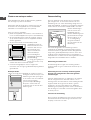
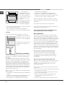
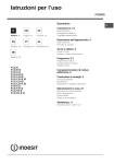
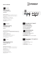
KN6 G110SA/NL
FR
Français
1
2
Mode d’emploi
CUISINIERE ET FOUR
Sommaire
Mode d’emploi,1
Description de l’appareil-Tableau de bord, 1
Description de l’appareil-Vue d’ensemble, 2
Installation,3
Mise en marche et utilisation,8
Utilisation du plan de cuisson,9
Précautions et conseils, 11
Nettoyage et entretien,12
Assistance,12
NL
Nederland
Gebruiksaanwijzing
FORNUIS EN OVEN
Inhoud
Gebruiksaanwijzing,1
Beschrijving van het apparaat-Bedieningspaneel,1
Beschrijving van het apparaat-Aanzichttekening,2
Installatie, 13
Starten en gebruik, 18
Gebruik van de oven,19
Voorzorgsmaatregelen en advies,21
Onderhoud en verzorging,22
Servicedienst,22
GB
English
Operating Instructions
COOKER AND OVEN
Contents
Operating Instructions,1
Description of the appliance-Control Panel,1
Description of the appliance-Overall view,2
Installation,23
Start-up and use,27
Cooking modes,28
Precautions and tips,30
Care and maintenance,31
Assistance,31
3
FR
4
5
Description de l’appareil
Tableau de bord
1.Manette PROGRAMMES
2.Voyant lumineux thermostat
3.Manette du THERMOSTAT
4.Manette du MINUTEUR
5.Manette BRULEURS
NL
Aanzichttekening
Bedieningspaneel
1.PROGRAMMAKNOP
2.Controlelampje THERMOSTAAT
3.THERMOSTAATKNOP
4.Knop TIMER*
5.Knoppen BRANDERS van de kookplaat
GB
Description of the appliance
Control panel
1.SELECTOR knob
2.THERMOSTAT indicator light
3.THERMOSTAT knob
4.TIMER knob*
5.Hob BURNER control knob
14
GB
7
1
2
3
8
9
10
11
12
13
4
5
6
6
IT
FR
Description de l’appareil
Vue d’ensemble
1. Brûleur à gaz
2. Grille du plan de cuisson
3. Tableau de bord
4. Support GRILLE
5. Support LECHEFRITE
6. Pied de réglage
7. Plateau du plan de cuisson
8. GLISSIERES de coulissement
9. niveau 5
10.niveau 4
11. niveau 3
12. niveau 2
13. niveau 1
14.Couvercle en verre (N’existe que sur certains modèles)
NL
UA
Aanzichttekening
Aanzichttekening
1. Gasbrander
2. Rooster van het fornuis
3. Bedieningspaneel
4. Ovenrek
5. Lekplaat of bakplaat
6. Stelschroeven
7.Plaat voor opvangen van overkooksel
8.Geleidersvan de roosters
9.stand 5
10.stand 4
11. stand 3
12. stand 2
13. stand 1
14.Glazen deksal (Slechts op enkele modellen aanwezig)
2
Description of the appliance
Overall view
1. Hob burner
2.Hob Grid
3.Control panel
4.Sliding grill rack
5.DRIPPING pan
6.Adjustable foot
7.Containment surface for spills
8.GUIDE RAILS for the sliding racks
9.position 5
10.position 4
11.position 3
12.position 2
13.position 1
14.Glass Cover *(Available only on
certain models)
Installation
FR
! Conserver ce mode d’emploi pour pouvoir le
consulter à tout moment. En cas de vente, de cession
ou de déménagement, veiller à ce qu’il suive l’appareil.
Local adjacent
A
! Lire attentivement les instructions : elles contiennent
des conseils importants sur l’installation, l’utilisation et la
sécurité de l’appareil
! L’installation de l’appareil doit être effectuée par
un professionnel du secteur conformément aux
instructions du fabricant.
! N’importe quelle opération de réglage, d’entretien
ou autre, doit être effectuée après avoir débranché la
prise de la cuisinière.
Local à ventiler
FR
B
A
Ouverture de ventilation
pour l’air comburant
Agrandissement de la
fissure entre la porte et
le de
sol l’appareil, il est
! Après une utilisation prolongée
conseillé d’ouvrir une fenêtre ou d’augmenter la vitesse
de ventilateurs éventuels.
Evacuation des fumées de combustion
! Les cuisinières destinés à la Holland sont réglés
en usine pour gaz Naturel Catégorie I2L; un ultérieur
réglage n’est donc pas nécessaire.
Aération des locaux
L’appareil doit être installé dans des locaux qui sont
aérés en permanence, selon les prescriptions des
Normes en vigueur dans le pays d’installation. Il est
indispensable que la pièce où l’appareil est installé
dispose d’une quantité d’air égale à la quantité d’air
comburant nécessaire à une bonne combustion du
gaz (le flux d’air doit être d’au moins 3 m3/h par kW de
puissance installée).
Les prises d’air, protégées par des grilles, doivent
disposer d’un conduit d’au moins 100 cm2 de section
utile et dans une position qui leur évite tout risque
d’être bouchées accidentellement, même partiellement
(voir figure A).
Ces ouvertures doivent être agrandies de 100%
(surface minimale 200 cm2) en cas d’appareils
dépourvus du dispositif de sécurité de flamme et
quand l’afflux de l’air provient de manière indirecte
de pièces voisines (voir figure B) - à condition qu’il ne
s’agisse pas de parties communes du bâtiment, de
chambres à coucher ou de locaux à risque d’incendie
– équipées d’un conduit d’aération avec l’extérieur
comme décrit plus haut.
La pièce doit prévoir un système d’évacuation vers
l’extérieur des fumées de combustion réalisé au moyen
d’une hotte reliée à une cheminée à tirage naturel ou
par ventilateur électrique qui entre automatiquement
en fonction dès qu’on allume l’appareil (voir figures).
Evacuation
directement à
l’extérieur
Evacuation par cheminée
ou conduit de fumée ramifié
(réservé aux appareils de
cuisson)
3
Positionnement et nivellement
Raccordement gaz
! L’appareil peut être installé à côté de meubles dont la
hauteur ne dépasse pas celle du plan de cuisson.
Pour le raccordement à la canalisation du gaz naturel
catégorie I2L la cuisinière est munie d’un filetage mâle
au pas du gaz conique 1/2”. Ce raccordement doit
être réalisé au moyen d’un tuyau rigide ou au moyen
d’un tuyau flexible conforme aux Normes Nationales eu
vigueur adéquat, muni de deux embouts métalliques
pour alimentation en gaz combustible plus léger que
l’air distribué par la canalisation. L’embout métallique
doit être raccordé
directement à l’entrée
“A” ou “C”. Selon le cas,
inverser la position du
bouchon.
! S’assurer que le mur en contact avec la paroi arrière
de l’appareil est réalisé en matériel ignifuge résistant à
la chaleur (T 90°C).
420 mm.
Min.
min. 650 mm. with hood
min. 700 mm. without hood
420 mm.
Pour une installation correcte :
• installer cet appareil dans une cuisine, une salle
à manger ou un studio (jamais dans une salle de
bains);
• si le plan de cuisson de la cuisinière dépasse le
plan de travail des meubles, il faut que ces derniers
soient placés à au moins 600 mm de l’appareil.
• si la cuisinière est installée sous un élément
suspendu, il faut que
ce dernier soit placé à
HOOD
au moins 420 mm de
Min. 600 mm.
distance du plan.
Il faut prévoir une
distance de 700 mm si
les éléments suspendus
sont inflammables (voir
figure);
• ne pas placer de
rideaux derrière ou sur
les côtés de la cuisinière à moins de 200 mm de
distance.
• pour l’installation de hottes, se conformer aux
instructions de leur notice d’emploi.
Min.
FR
Il est conseillé
d’effectuer le
C
raccordement du côté
qui est le plus proche
de l’alimentation en gaz. En amont de l’appareil il
faut installer un robinet d’arrêt du gaz conforme aux
Normes Nationales eu vigueur; il devra être installé de
manière à pouvoir facilement le manoeuvrer. Quand
l’appareil ne fonctionne pas, il est recommandé de
fermer le robinet mural du gaz.
A
Raccordement avec tuyau rigide avec raccords
filetés
Le raccordement à la tuyauterie du gaz doit être
effectué de manière à ne provoquer aucune contrainte
à l’appareil.
Nivellement
Pour mettre l’appareil bien à plat, visser les pieds
de réglage fournis aux
emplacements prévus aux
coins à la base de la cuisinière
(voir figure).
Montage des pieds* par
encastrement sous la base.
Raccordement avec tuyau flexible moulé en une
seule piéce
Utiliser exclusivement des tuyaux conformes à la
Norme en vigueur et des joints d’étanchéité conformes
à la Norme en vigueur. La mise en service de ces
tuyaux doit être effectuée de manière à ce que leur
longueur ne dépasse pas 2000 mm. en extension
maximum. Après avoir effectué le branchement, veillez
à ce que le tuyau flexible ne soit pas écrasé ni placé
contre des parties mobiles.
Vérification de l’étanchéitè
Une fois l’installation terminée, vérifier l’étanchéité de
tous les raccords en utilisant une solution savonneuse
et jamais une flamme.
4
Branchement du câble d’alimentation au réseau
électrique
FR
Le branchement électrique doit être effectué
conformément aux normes NEN 1010 et aux
prescriptions en vigueur sur le territoire national de
l’utilisateur. Pour le raccordement à la ligne électrique,
les cuisinières sont équipées d’un câble à trois
conducteurs, dont la tension et la fréquence doivent
correspondre aux valeurs figurant sur la plaquette des
caractéristiques. Avant d’effectuer le branchement,
assurez-vous que:
Giaune-Vert: Terre
Bleue:
neutre
Marron:
Phase
En cas de branchement direct au réseau, intercaler
entre l’appareil et l’installation électrique un interrupteur
omnipolaire.
Le câble d’alimentation ne doit pas être soumis à des
températures supérieures de 50°C à celle ambiante.
Avant de procéder au branchement, vérifier que:
• le plomb réducteur et l’installation de l’appartement
peuvent supporter la charge de l’appareil (voir
plaquette des caractéristiques);
• l’installation électrique est bien équipée d’une mise
à la terre efficace conformément aux normes et
dispositions de la loi;
• la prise ou l’interrupteur omnipolaire peuvent
aisément être atteints à cuisinière installée.
! N’utiliser ni réducteurs, ni adaptateurs, ni dérivations
car ils pourraient provoquer des surchauffes ou des
brûlures.
5
FR
Tableau Caractéristiques des brûleurs et des injecteurs
Tableau 1
Gaz naturels
Brűleur
Diamčtre
(mm)
Puissance thermique
kW (p.c.s.*)
Injecteur
1/100
Débit*
l/h
Nom.
Red.
(mm)
G25
Rapide (R)
100
3,00
0,70
116
332
Semi Rapide
(Moyen) (S)
75
1,90
0,40
106
210
Auxiliaire
(Petit) (A)
55
1,00
0,40
79
111
Pression de alimentation
Nominale (mbar)
Minimum (mbar)
Maximum (mbar)
25
15
30
* A 15°C et 1013 mbar-gaz sec
Naturel G25
P.C.S. = 32,49 MJ/m3
CARACTERISTIQUES TECHNIQUES
Dimensions du
32x43,5x40 cm
four HxLxP
Volume
l 56
Dimensions utiles largeur 42 cm
du tiroir chauffeprofondeur 46 cm
plats
hauteur 8,5 cm
adaptables à tous les types de gaz
Brûleurs
indiqués dans la plaque
signalétique
Tension et
fréquence
voir plaque signalétique
d’alimentation
Directive 2002/40/CE sur l'étiquette
des fours électriques Norme EN
50304
ETIQUETTE
ENERGIE
Consommation énergie déclaration
Classe convection Naturelle –
S
R
S
A
KN6 G110SA/NL
6
Statique.
fonction four :
Directives Communautaires:
2006/95/EC du 12/12/06 (Basse
Tension) et modifications
successives - 2004/108/EC du
15/12/04 (Compatibilité
Electromagnétique) et modifications
successives -2009/142/EC du
30/11/09 (Gaz) et modifications
successives 93/68/EEC du
22/07/93 et modifications
successives - 2002/96/EEC.
Mise en marche et utilisation
Utilisation du plan de cuisson
Allumage des brûleurs
Un petit cercle plein près de chaque bouton BRULEUR
indique le brûleur associé à ce dernier.
Pour allumer un brûleur du plan de cuisson :
1. approcher une flamme ou un allume-gaz ;
2. pousser sur le bouton du BRULEUR tout en le
tournant dans le sens inverse des aiguilles d’une
montre jusqu’au symbole grande flamme E.
3. pour régler la puissance de la flamme souhaitée,
tourner le bouton BRULEUR dans le sens inverse
des aiguilles d’une montre : sur la position minimum
C, sur la position maximum E ou sur une position
intermédiaire.
Pour allumer le brûleur choisi, appuyez à fond sur la
manette correspondante et tournez-la dans le sens
inverse des aiguilles d'une montre jusqu'à la position
maximum E tout en continuant à appuyer jusqu'au
déclenchement du train d'étincelles.
! En cas d’extinction accidentelle des flammes,
éteindre le brûleur et attendre au moins 1 minute avant
de tenter de rallumer.
Si l’appareil est équipé
d’un dispositif de sécurité*
de flamme, pousser sur le
bouton BRULEUR pendant
2-3 secondes pour garder
la flamme allumée et pour
activer le dispositif.
Pour éteindre le brûleur,
tourner le bouton jusqu’à
la position d’arrêt •.
Conseils pratiques pour l’utilisation des brûleurs
Pour un meilleur rendement des brûleurs et une
moindre consommation de gaz, utiliser des casseroles
à fond plat, munies de couvercle et d’un diamètre
adapté au brûleur :
Pour repérer le type de brûleur adéquat, se référer aux
dessins du paragraphe “Caractéristiques des brûleurs
et des injecteurs”.
Brűleur
ř Diamčtre récipients (cm)
Rapide (R)
24 – 26
Semi-Rapide (S)
16 – 20
Auxiliaire (A)
10 – 14
! Pour les modèles équipés d’une grille de réduction,
n’utiliser cette dernière que pour le brûleur auxiliaire,
en cas d’utilisation de casseroles ayant moins de 12
cm de diamètre.
FR
Utilisation du four
! Lors de son premier allumage, faire fonctionner
le four à vide, porte fermée, pendant au moins une
heure en réglant la température à son maximum.
Puis éteindre le four, ouvrir la porte et aérer la pièce.
L’odeur qui se dégage est due à l’évaporation des
produits utilisés pour protéger le four.
! Avant toute utilisation, enlever les pellicules
plastiques sur les côtés de l’appareil
! Ne jamais poser d’objets à même la sole du four,
l’émail risque de s’abîmer.
1. Pour sélectionner le programme de cuisson
souhaité, tourner le bouton PROGRAMMES.
2. Choisir la température conseillée pour ce
programme ou celle qu’on préfère à l’aide du bouton
THERMOSTAT.
Un tableau de cuisson sert de guide et indique
notamment les températures conseillées pour plusieurs
préparations culinaires (voir tableau cuisson au four).
En cours de cuisson, il est possible à tout moment de :
• modifier le programme de cuisson à l’aide du
bouton PROGRAMMES;
• modifier la température à l’aide du bouton
THERMOSTAT;
• interrompre la cuisson en ramenant le bouton
PROGRAMMES sur “0”.
! Il faut toujours enfourner les plats sur la grille fournie
avec l’appareil.
Voyant THERMOSTAT
Allumé, il signale la montée en chaleur du four. Il
s’éteint dès que la température sélectionnée est
atteinte. Le voyant s’allume et s’éteint tour à tour pour
indiquer que le thermostat fonctionne et maintient la
température au degré près.
ATTENTION! Le couvercle en verre
peut se casser s’il est chauffé. Il
faut éteindre tous les brûleurs et les
plaques électriques avant de le fermer. *Ne concerne que les modèles
équipés de couvercle en verre
7
FR
Eclairage du four
Pour l’allumer, amener le bouton PROGRAMMES
sur une position autre que la position “0”. Il reste
allumé tant que le four est en marche. Si le bouton est
amené sur , la lampe s’allume sans activer aucune
résistance.
Minuteur
Pour actionner le Minuteur procéder comme suit :
1. tourner le bouton MINUTEUR et faire un tour
presque complet dans le sens des aiguilles d’une
montre 4 pour remonter la sonnerie;
2. tourner le bouton MINUTEUR dans les sens inverse
des aiguilles d’une montre 5 pour sélectionner la
durée désirée.
8
Programmes de cuisson
Conseils de cuisson
! Pour tous les programmes il est possible de
sélectionner une température comprise entre 60°C et
MAX., sauf pour le programme GRIL, pour lequel il est
préconisé de sélectionner MAX.
! En cas de cuisson en mode GRIL, placer la lèchefrite
au gradin 1 pour récupérer les jus de cuisson.
Programme FOUR STATIQUE
Mise en marche des résistances de voûte et de sole.
Pour cette cuisson traditionnelle mieux vaut cuire
sur un seul niveau : la cuisson sur plusieurs niveaux
entraînerait une mauvaise distribution de la chaleur.
FR
GRIL
• Placer la grille au gradin 3 ou 4, enfourner les plats
au milieu de la grille.
• Nous conseillons de sélectionner le niveau d’énergie
maximum. Ne pas s’inquiéter si la résistance de
voûte n’est pas allumée en permanence: son
fonctionnement est contrôlé par un thermostat.
Programme Pâtisserie
PIZZA
L’élément chauffant inférieur est branché. Cette
position est conseillée pour parfaire la cuisson
d’aliments (placés dans des plats à rôti) qui sont déjà
bien cuits à la surface mais encore mous à l’intérieur
ou pour des gâteaux garnis de fruits ou de confiture
qui ont besoin de se colorer modérément à leur
surface. A remarquer que cette fonction ne permet pas
d’atteindre une température maximum à l’intérieur du
four (250°C), il est par conséquent déconseillé de cuire
en maintenant longuement le four dans cette position
à moins qu’il ne s’agisse de gâteaux qui exigent des
températures inférieures ou égales à 180°C.
• Utiliser un plat en aluminium léger et l’enfourner sur
la grille du four.
En cas d’utilisation du plateau émaillé, le temps de
cuisson sera plus long et la pizza beaucoup moins
croustillante.
• Si les pizzas sont bien garnies, n’ajouter la
mozzarelle qu’à mi-cuisson.
Programme Résistance de voûte
Mise en marche de la résistance de voûte. La
température plutôt élevée et directe du gril permet de
saisir immédiatement les viandes évitant ainsi qu’elles
ne durcissent en perdant leur jus.
Programme GRIL
Mise en marche de la résistance de voûte et du
tournebroche. La cuisson au gril est particulièrement
recommandée pour les plats qui exigent une
température élevée à leur surface : côtes de veau et
de bœuf, entrecôtes, filet, hamburgers, etc...
! Les cuissons GRIL doivent avoir lieu porte fermée.
9
FR
Tableau de cuisson au four
Poids
(Kg)
Position
gradins en
partant du
bas
Temps de
préchauffage
(minutes)
Position
sélecteur de
températures
Temps de
cuisson
(minutes)
Canard
Rôti de veau ou de bś uf
Rôti de porc
Biscuits (pâte brisée)
Tartes
Lasagnes
Agneau
Maquereau
Plum-cake
Choux
Génoise
Quiches
1
1
1
1
1
1
1
1
0.3
0.5
1.5
3
3
3
3
3
3
2
2
2
3
3
3
15
15
15
15
15
10
10
10
10
10
10
15
200
200
200
180
180
190
180
180
170
180
170
200
65-75
70-75
70-80
15-20
30-35
35-40
50-60
30-35
40-50
30-35
20-25
30-35
Gâteaux levés
Tartes
Gâteaux aux fruits
Brioches
0,5
1
1
0,5
3
3
3
3
15
15
15
15
160
180
180
160
30-40
35-40
50-60
25-30
3 Résistance Pour parfaire la cuisson
de voűte
-
3/4
15
220
-
4 Gril
1
4
5
Max
8-10
1
1
1
1
1
1
1
n.° 4
4
4
3/4
4
4
4
4
4
5
5
5
5
5
5
5
5
Max
Max
Max
Max
Max
Max
Max
Max
6-8
10
10-15
15-20
15-20
7-10
15-20
2-3
Position
sélecteur
Aliments ŕ cuire
1 Statique Traditionnel
2 Four
Pâtisserie
Soles et seiches
Brochettes de calmars et
crevettes
Tranches de colin
Légumes grillés
Côte de veau
Côtelettes
Hamburgers
Maquereaux
Croque-monsieur
N.B. : les temps de cuisson sont purement indicatifs et peuvent ętre modifiés selon les goűts de chacun. En cas
de cuisson au gril, placez toujours la lčchefrite sur le 1er gradin en partant du bas.
10
Précautions et conseils
! Cet appareil a été conçu et fabriqué conformément
aux normes internationales de sécurité.
Ces consignes de sécurité sont très importantes et
doivent être lues attentivement.
Sécurité générale
• Cet appareil a été conçu pour un usage familial, de
type non professionnel.
• Cet appareil ne doit pas être installé en extérieur,
même dans un endroit abrité, il est en effet très
dangereux de le laisser exposé à la pluie et aux
orages.
• Ne pas toucher l’appareil avec les mains mouillées
ou humides ou si l’on est pieds nus.
• Cet appareil qui sert à cuire des aliments ne doit
être utilisé que par des adultes conformément aux
instructions du mode d’emploi.
• Cette notice concerne un appareil classe 1 (libre
pose) ou classe 2 - sous-classe 1 (encastré entre
deux meubles).
• En cours de fonctionnement, les éléments
chauffants et certaines parties de la porte
peuvent devenir très chauds. Attention à ne pas
les toucher et à garder les enfants à distance.
• ne laissez pas utiliser l’appareil par des enfants
ou par des personnes incapables de le faire, sans
surveillance.
• Eviter que le cordon d’alimentation d’autres petits
électroménagers touche à des parties chaudes de
l’appareil.
• Les orifices ou les fentes d’aération ou d’évacuation
de la chaleur ne doivent pas être bouchés
• Utiliser toujours des gants de protection pour
enfourner ou sortir les plats du four.
• Ne pas utiliser de solutions inflammables (alcool,
essence..) à proximité de l’appareil lorsqu’il est en
marche.
• Ne pas stocker de matériel inflammable dans la
niche de rangement du bas ou dans le four : si
l’appareil était par inadvertance mis en marche, il
pourrait prendre feu.
• Les surfaces intérieures du tiroir (s’il y en a un)
peuvent devenir chaudes.
• Quand l’appareil n’est pas utilisé, s’assurer que les
boutons sont bien sur la position •.
• Ne pas tirer sur le câble pour débrancher la fiche de
la prise de courant.
• N’effectuer aucune opération de nettoyage ou
d’entretien sans avoir auparavant débranché la fiche
de la prise de courant.
• En cas de panne, n’essayer en aucun cas d’accéder
aux mécanismes internes pour tenter de réparer
l’appareil. Faire appel au service d’assistance.
• Ne pas poser d’objets lourds sur la porte du four
ouverte.
• S’assurer que les enfants ne jouent pas avec
l’appareil.
• Essuyez tout liquide pouvant se trouver sur le
couvercle avant de l’ouvrir.
• Cet appareil n’est pas prévu pour être utilisé par
des personnes (y compris les enfants) dont les
capacités physiques, sensorielles ou mentales sont
réduites, ou des personnes dénuées d’expérience
ou de connaissance, sauf si elles ont pu bénéficier,
par l’intermédiaire d’une personne responsable de
leur sécurité, d’une surveillance ou d’instructions
préalables concernant d’utilisation de l’appareil.
Mise au rebut
• Mise au rebut du matériel d’emballage : se
conformer aux réglementations locales, les
emballages pourront ainsi être recyclés.
• La directive européenne 2002/96/CE relative aux
déchets d’équipements électriques et électroniques
(DEEE), prévoit que les électroménagers ne peuvent
pas être traités comme des déchets solides urbains
courants. Les appareils usagés doivent faire l’objet
d’une collecte séparée pour optimiser le taux de
récupération et de recyclage des matériaux qui les
composent et empêcher tout danger pour la santé
et pour l’environnement. Le symbole de la poubelle
barrée est appliqué sur tous les produits pour
rappeler qu’ils font l’objet d’une collecte sélective.
Pour de plus amples renseignements sur la mise
au rebut des électroménagers, les possesseurs
peuvent s’adresser au service public prévu à cet
effet ou aux commerçants.
Economies et respect de
l’environnement
• Pour faire des économies d’électricité, utiliser autant
que possible le four pendant les heures creuses.
• Pour les cuissons au GRIL, nous recommandons de
garder la porte du four fermée: les résultats obtenus
sont meilleurs et la consommation d’énergie est
moindre (environ 10% d’économie).
• Garder les joints propres et en bon état pour qu’ils
adhèrent bien à la porte et ne causent pas de
déperdition de chaleur.
11
FR
Nettoyage et entretien
FR
Mise hors tension
Contrôler les joints du four
Avant toute opération de nettoyage ou d’entretien
couper l’alimentation électrique de l’appareil.
Contrôler périodiquement l’état du joint autour de la
porte du four. S’il est abîmé, s’adresser au service
après-vente le plus proche de chez soi. Mieux vaut ne
pas utiliser le four tant qu’il n’est pas réparé.
Nettoyage de l’appareil
! Ne jamais nettoyer l’appareil avec des nettoyeurs
vapeur ou haute pression.
Remplacement de l’ampoule d’éclairage
du four
• Nettoyer l’extérieur émaillé ou inox et les joints
en caoutchouc à l’aide d’une éponge imbibée
d’eau tiède additionnée de savon neutre. Si
les taches sont difficiles à enlever, utiliser des
produits spéciaux. Rincer abondamment et
essuyer soigneusement. Ne pas utiliser de poudres
abrasives ni de produits corrosifs.
1. Débrancher le four, enlever
le couvercle en verre du
logement de la lampe (voir
figure).
2. Dévisser l’ampoule et la
remplacer par une autre de
même type : tension 230 V,
puissance 25 W, culot E 14.
3. Remonter le couvercle et rebrancher le four au
réseau électrique.
• Les grilles, les chapeaux, les couronnes et les
brûleurs du plan de cuisson sont amovibles et
peuvent ainsi être nettoyés plus facilement. Pour
les laver, utiliser de l’eau chaude additionnée d’un
détergent non abrasif, éliminer toute incrustation et
attendre qu’ils soient parfaitement secs avant de les
remonter.
• Nettoyer fréquemment l’extrémité des dispositifs de
sécurité* de flamme.
• Nettoyer l’enceinte après toute utilisation, quand le
four est encore tiède. Utiliser de l’eau chaude et du
détergent, rincer et essuyer avec un chiffon doux.
Eviter tout produit abrasif.
• Nettoyer la vitre de la porte avec des produits non
abrasifs et des éponges non grattantes, essuyer
ensuite avec un chiffon doux. Ne pas utiliser de
matériaux abrasifs ou de racloirs métalliques
aiguisés qui risquent de rayer la surface et de briser
le verre.
• Les accessoires peuvent être lavés comme de la
vaisselle courante, même au lave-vaisselle.
• Eviter de fermer le couvercle si les brûleurs sont
allumés ou encore chauds. Essuyez tout liquide
pouvant se trouver sur le couvercle avant de l’ouvrir.
12
Entretien robinets gaz
Il peut arriver qu’au bout d’un certain temps, un
robinet se bloque ou tourne difficilement. Il faut alors le
remplacer.
! Cette opération doit être effectuée par un
technicien agréé par le fabricant.
Assistance
! Ne jamais faire appel à des techniciens non agréés.
Indiquer :
• le type d’anomalie;
• le modèle de l’appareil (Mod.)
• son numéro de série (S/N)
Ces informations figurent sur la plaque signalétique
apposée sur l’appareil
Installatie
! Bewaar dit instructieboekje zorgvuldig voor eventuele
raadpleging in de toekomst. In het geval u het
apparaat verkoopt of u verhuist, moet u het boekje bij
het apparaat bewaren.
! Lees de instructies aandachtig door: er staat
belangrijke informatie in over installatie, gebruik en
veiligheid.
Aangrenzend vertrek
Te ventileren vertrek
A
B
NL
A
! De installatie van het apparaat moet volgens deze
instructies worden uitgevoerd door een bevoegde
installateur.
Ventilatieopening voor
Vergroting van de kier
verbrandingslucht
tussen de deur en de vloer
! Na een langdurig gebruik van het apparaat is het aan
te raden een raam te openen of de draaisnelheid van
eventuele ventilatoren te vermeerderen.
!Sluit altijd eerst de elektrische stroom af voordat u tot
onderhoud of regeling van het fornuis overgaat.
Afvoer van de verbrandingsgassen
! De inbouwgasfornhuizen voor Nederland, zijn in de
fabriek afgesteld voor Natuurlijk gas categorie I2L, het
is niet nodig om dit nogmaals af te stellen.
Ventilatie van de vertrekken
Dit apparaat mag uitsluitend worden geïnstalleerd in
permanent geventileerde ruimten, overeenkomstig
de geldende nationale voorschriften. In het vertrek
waar het apparaat wordt geïnstalleerd moet zoveel
lucht kunnen toestromen als nodig is voor de normale
gasverbranding (de luchtcapaciteit mag niet minder
zijn dan 2 m3/h per kW geïnstalleerd vermogen).
De luchttoevoeropeningen, beschermd door roosters,
moeten voorzien zijn van een leiding met een minstens
100 cm 2 bruikbare doorsnede en zo moeten zijn
geplaatst dat ze, zelfs niet gedeeltelijk, worden
verstopt, (zie afbeelding A).
Deze openingen moeten met 100% worden verbreed
- met een minimum van 200 cm 2 - als het fornuis
niet voorzien is van een thermokoppelbeveiliging en
wanneer de toevoer van lucht op indirecte manier van
aangrenzende vertrekken plaatsvindt (zie afbeelding
B) - mits dit geen gemeenschappelijke ruimtes zijn
van het gebouw, vertrekken met een verhoogd
brandgevaar of slaapkamers, die beschikken over een
ventilatieopening die verbonden is met buiten, zoals
zojuist beschreven.
De afvoer van de verbrandingsgassen moet
plaatsvinden door middel van een afzuigkap die
is aangesloten op een veilige en goedwerkende
schoorsteen met natuurlijke trek, ofwel door middel
van een elektrische ventilator die automatisch in
werking treedt elke keer dat u het apparaat aanzet (zie
afbeeldingen).
Afvoer rechtstreeks
naar buiten
Afvoer door een schoorsteen
of vertakt rookkanaal
(alleen bestemd voor
kookapparaten)
13
Plaatsen en waterpas zetten
Gasaansluiting
! Het apparaat kan naast meubels worden geplaatst
die niet hoger zijn dan het werkvlak.
Voor het aansluiten aan de buis van het natuurlijk
gas categorie I2L, is het fornuis voorzien van een
aansluiting van 1/2”. Deze aansluiting vraagt om een
harde buis (NBN D. 51-003) of een buigzame slang die
voldoet aan de voorschriften ARGB 03-80, met twee
metalen aansluitingen
voor de toevoer van
brandbaar gas. De
metalen aansluiting moet
goed worden bevestigd
aan de ingang “A” of
“C”. Al naar gelang
A
het geval verandert
C
men de positie van de
aansluiting.
! Controleer dat de wand die in contact komt met de
achterkant van het apparaat van niet ontvlambaar
materiaal is en bestand tegen hitte (T 90°C).
420 mm.
Min.
min. 650 mm. with hood
min. 700 mm. without hood
420 mm.
Voor een correcte installatie:
• plaats het apparaat in de keuken, in de eetkamer of
in een eenkamerappartement (niet in de badkamer);
• als het kookvlak hoger is dan de meubels, moeten
zij op minstens 600 mm van het apparaat vandaan
worden geplaatst;
• als het fornuis onder een keukenkastje wordt
geïnstalleerd, moet de
afstand tussen de twee
HOOD
minstens 420 mm zijn.
Min. 600 mm.
Deze afstand moet
700 mm worden als
de keukenkastjes
zijn vervaardigd uit
ontvlambaar materiaal
(zie afbeelding);
• hang geen gordijnen
achter het fornuis, of op
minder dan 200 mm vanaf de zijkant;
• eventuele afzuigkappen moeten volgens de
instructies van hun eigen gebruiksaanwijzing worden
geïnstalleerd.
Min.
NL
Waterpas zetten
Indien het nodig is het apparaat te nivelleren, kunnen
de bijgeleverde stelvoetjes in de
daarvoor geschikte openingen
in de hoeken van het onderstuk
van het fornuis worden
geschroefd (zie afbeelding).
De poten* moeten aan het
onderstuk van het fornuis vast
worden gezet.
Het wordt aangeraden de aansluiting zo dicht
mogelijk bij de gaskraan te bewerkstelligen. Boven
het fornuis moet een gaskraan worden aangebracht
volgens de geldendeplaatselijke normen; deze moet
zodanig worden aangebracht dat hij gemakkelijk te
manoeuvreren is. Als het fornuis niet in gebruik is wordt
aangeraden de hoofdkraan dicht te draaien.
Aansluiting met harde buis
De aansluiting aan het gas moet zodanig worden
uitgevoerd dat het geen enkele druk uitoefent op het
apparaat.
Aansluiting met een roestvrije stalen buigzame
buis aan een onafgebroken wand met gedrade
aanhechtingen
Gebruik uitsluitend buizen en pakkingen, die voldoen
aan de voorgeschreven nationale normen. Het in
werking stellen van deze buizen moet zodanig worden
uitgevoerd dat de lengte van de buizen, geheel
uitgestrekt, niet meer dan 2000 mm is. Nadat de
aansluiting heeft plaats gevonden moet U kontroleren
dat de slang niet in kontakt is met beweegbare delen
of dat hij knel zit.
Controle van de dichting
Als het fornuis geinstalleerd is moet men de perfekte
luchtdichtheid van de aansluitingen kontroleren met
zeepsop, nooit met een vlam.
14
Het aansluiten van de voedingskabel aan het net
NL
Elektrische aansluiting dient te geschieden volgens
de norm NEN 1010, plus plaatselijk geldende
voorschriften. De fornuizen zijn voorzien van een drieaderig snoer en geschikt om aangesloten te worden
op wisselstroom met een spanning en frekwentie die
aangegeven worden op het typeplaatje. De klueren
van het netsnoer komen overeen met:
Groen-geel: aarde
Blauw:
nul
Bruin: fase
Wanner het fornuis niet door middel van buigzame
leidingen aangesloten is, moet in de installatie een
meerpolige schakelaar aangebracht worden.
De voedingskabel moet zodanig geplaatst zijn, dat hij
nergens een temperatuur bereikt die 50°C hoger is dan
de kamertemperatuur. Voor het aansluiten moet men
kontroleren dat:
• de zekeringen en de leidingen geschikt zijn om het
vermogen te leveren dat door het fornuis zal worden
afgenomen (zie plaatje met technische gegevens);
• de aardleiding in overeenstemming is met de
bepalingen van de geldende normen en met de
wetgeving terzake;
• het stopkontakt of de tweepolige schakelaar
gemakkelijk bereikkbaar zijn nadat de oven
geplaatst is.
! gebruik geen adaptors, dubbelstekkers of dergelijke,
aangezien deze oververhitting en branden kunnen
veroorzaken.
15
NL
Tabel eigenschappen branders en sproeiers
Tabel 1
Natuurlijk gas
Branders
Doorsenee
(mm)
Thermisch vermogen
kW (p.c.s. *)
Straal. 1/100
Bereik*
(l/h)
Nom.
Gered.
(mm)
G25
Snel
(Groot) (R)
100
3,00
0,70
116
332
Half Snel (Medium) (S)
75
1,90
0,40
106
210
Hulp
(Klein) (A)
55
1,00
0,40
79
111
Spanning van voeding
Nominale (mbar)
Minimum (mbar)
Maximum (mbar)
25
15
30
** A 15°C en 1013 mbar-droog gas
P.C.S. Natuurlijk gas G25 = 32,49 MJ/m³
S
R
S
A
KN6 G110SA/NL
TECHNISCHE
GEGEVENS
Afmetingen Oven
HxBxD
Inhoud
Afmetingen van de
verwarmingslade
liter 56
breedte 42 cm
diepte 46 cm
hoogte 8,5 cm
Branders
geschikt voor alle soorten gas
aangegeven op het typeplaatje
Spanning en
frequentie van de
elektrische voeding
zie typeplaatje
ENERGY LABEL
16
32x43,5x40 cm
Richtlijn 2002/40/EG op etiket
van elektrische ovens. Norm EN
50304
Energieverbruikverklaring Klasse
Natuurlijk convectie verwarmingsfunctie:
Statisch.
EU Richtlijnen: 2006/95/EC van
12/12/06 (Laagspanning) en
daaropvolgende wijzigingen 2004/108/EC van 15/12/04
(Elektromagnetische
Compatibiliteit) en
daaropvolgende wijzigingen 2009/142/EC van 30/11/09 (Gas)
en daaropvolgende wijzigingen 93/68/EEC van 22/07/93 en
daaropvolgende wijzigingen 2002/96/EC.
Starten en gebruik
Gebruik van de kookplaat
Aansteken van de branders
Naast elke BRANDER knop wordt met een vol rondje
aangegeven bij welke brander deze knop hoort.
Om een brander van de kookplaat aan te steken:
1. houd een vlam of aansteker bij de brander;
2. druk en draai tegelijkertijd de BRANDER knop
linksom tot aan het symbool van de grootste vlam E.
3. regel de sterkte van de gewenste vlam, door de
BRANDER knop linksom te draaien: op het minimum C,
op het maximum E of op een tussenliggende stand.
Voor het aansteken van de gewenste gasbrander drukt
u de bijhorende knop geheel in en draait u hem tegen
de klok in tot aan de
maximum E stand; houd
hem ingedrukt totdat de
brander aan is.
! Mocht de vlam per
ongeluk uitgaan, doe
dan de brander uit en
wacht minstens 1 minuut
voordat u hem weer probeert aan te steken.
Als het apparaat is voorzien van een
thermokoppelbeveiliging* dient u de BRANDER knop
circa 2-3 seconden ingedrukt te houden om de vlam
aan te houden en de beveiliging te activeren.
Om de brander uit te zetten draait u aan de knop tot hij
op uit staat •.
Praktisch advies voor het gebruik van de branders
Voor een beter rendement van de branders en een
minimaal gasverbruik dient u pannen te gebruiken
met een platte onderkant, die voorzien zijn van een
deksel en die afgestemd zijn op de afmetingen van de
brander:
Om het type brander te selecteren kunt u de
tekeningen raadplegen die staan weergegeven in het
hoofdstuk “Eigenschappen branders en sproeiers”.
Branders
ř Diameter pan (cm)
! Op modellen die voorzien zijn van een
vlamverspreider moet deze alleen worden gebruikt op
de extra brander wanneer men pannen gebruikt die
een doorsnede hebben van minder dan 12 cm.
Gebruik van de oven
! Wij raden u aan bij het eerste gebruik de oven
minstens een uur leeg te laten functioneren, op
maximum temperatuur en met de deur dicht. Nadat u
de oven heeft uitgeschakeld, opent u de ovendeur en
lucht u het vertrek. De lucht die u ruikt komt door het
verdampen van de middelen die worden gebruikt om
de oven te beschermen.
! Vóór gebruik is het strikt noodzakelijk het plastic folie
aan de zijkanten van het apparaat te verwijderen.
! Zet nooit voorwerpen op de bodem van de oven; u
riskeert hiermee het email te beschadigen.
1. Selecteer het gewenste kookprogramma door aan
de PROGRAMMAKNOP te draaien.
2. Kies de aangeraden temperatuur voor het
betreffende programma of de door u gewenste
temperatuur door aan de THERMOSTAATKNOP te
draaien.
Een lijst met kooktijden en aanbevolen
kooktemperaturen kunt u terugvinden in de speciale
tabel (zie Kooktabel oven).
Tijdens het koken kunt u nog altijd:
• het kookprogramma veranderen met behulp van de
PROGRAMMAKNOP;
• de temperatuur veranderen met behulp van de
THERMOSTAATKNOP;
• het koken onderbreken door de PROGRAMMAKNOP
weer op stand “0” te zetten.
! Plaats de ovenschalen altijd op bijgeleverde roosters.
Controlelampje THERMOSTAAT
Het oplichten van dit lampje geeft aan dat de
oven aan het verwarmen is. Het licht gaat uit als
de geselecteerde temperatuur is bereikt. Vanaf dit
moment gaat het controlelampje aan en uit, hetgeen
aangeeft dat de thermostaat werkt en de temperatuur
in de oven constant houdt.
Snel (R)
24 – 26
Half-snel (S)
16 – 20
BELANGRIJK! De glazen afdekplaat kan bre-
Spaarbrander (A)
10 – 14
ken bij oververhitting. Doe alle branders of
eventuele elektrische kookplaten uit voordat
u hem dicht doet.*Betreft alleen modellen met
glazen deksel
17
NL
NL
Ovenverlichting
De verlichting gaat aan door de PROGRAMMAKNOP
in een willekeurige stand (behalve “0”) te zetten. Hij
zal aanblijven totdat de oven werkt. Door met de
knop te selecteren gaat het licht aan zonder dat de
verwarming wordt ingeschakeld.
Timer
Voor het activeren van de Timer gaat u als volgt te
werk:
1. draai de TIMERKNOP bijna 360° rechtsom 4 om de
wekker op te laden;
2. draai de TIMERKNOP linksom 5 en stel de
gewenste tijd in.
18
Kookprogramma’s
! U kunt voor alle programma’s een temperatuur tussen
de 60°C en MAX instellen, behalve:
• GRILL (hierbij is het aanbevolen alleen MAX te
gebruiken);
Statische oven
In deze stand gaan de twee onderste en bovenste
verwarmingselementen aan. Dit is de klassieke,
ouderwetse oven, die verheven is tot een
uitzonderlijk niveau van temperatuurverspreiding
en energiebesparing. De traditionele oven blijft
onovertroffen voor ovenschotels zoals b.v. : kool
met varkensribben, stokvis op zijn Spaans, rijst met
kalfsvlees enz.... Uitstekende resultaten krijgt u bij
het koken van vleesgerechten zoals: gestoofd vlees,
goulash, gevogelte, varkenshaas enz...die langzaam
gaar gekookt en bedropen moeten worden. Het is
ook het beste systeem voor het bakken van taarten
en koekjes, gestoofde vruchten en voor het koken in
speciaal voor de oven geschikte pannen. Bij het koken
in de statische oven gebruikt u slechts één ovenstand,
aangezien met meer ovenstanden in gebruik de
temperatuur slecht verdeeld zou zijn. Bij gebruik van
meerdere roosters kunt u de hoeveelheid warmte
tussen de bovenste stand en de onderste stand tegen
elkaar afwegen. Als meer boven- of onderwarmte
vereist is, zet u de schotel hoger of lager in de oven.
U vindt enkele voorbeelden in de tabel „Praktische
raadgevingen voor het koken”.
NL
Praktische kooktips
! Bij de functie GRILL raden wij u aan de lekplaat op
stand 1 te zetten om eventueel vet of jus op te vangen.
GRILL
• Plaats de grill op stand 3 of 4, plaats de gerechten
op het midden van de grill.
• Het is normaal dat het bovenste verwarmingselement
niet constant aan blijft: zijn werking wordt geregeld
door een thermostaat.
PIZZA
• Gebruik een lichte aluminium ovenschaal en zet hem
op het bijgeleverde ovenrooster.
Bij gebruik van de bakplaat duurt het langer en krijgt
u waarschijnlijk geen krokante pizza.
• Bij zeer gevulde pizza’s raden wij aan de mozzarella
of andere kaas pas halverwege de kooktijd toe te
voegen.
Gebak-oven
Het onderste verwarmingselement gaat aan.
Deze functie wordt aangeraden voor het bakken van
fijne gerechten en vooral voor taarten die moeten rijzen
en dus meer warmte nodig hebben die van onderaf
komt.
Viene fatto notare che le temperature più elevate
vengono raggiunte in tempi piuttosto lunghi, pertanto in
questi casi è consigliabile utilizzare la funzione „Forno
Statico”.
Oven „boven”
Het bovenste verwarmingselement gaat aan.
Deze functie kan worden gebruikt voor het afmaken
van een gerecht.
Grill
Het centrale bovenste verwarmingselement gaat aan.
De hoge en rechtstreekse hitte bruint de oppervlakten
van het vlees onmiddellijk zodat er geen vocht verloren
gaat en de binnenkant mals blijft. Het koken onder de
grill is vooral aan te raden voor gerechten die een hoge
temperatuur aan de buitenkant nodig hebben: biefstuk,
entrecôte, filet, hamburger etc...
19
NL
Kooktabel oven
Positie
keuzeknop
Gerecht
Kooktijd
Positie
Voorverwarming
thermostaa- (minuten)
(minuten)
tknop
Gewicht
(kg)
Positie ovenrek
van beneden af
Eend
Braadstuk Varkensvlees
Koekjes (kruimeldeeg)
Jamtaart
Lasagne
Lamsvlees
Makreel
Plum-cake
Beignets
Pan di spagna
Quiche
1
1
1
1
1
1
1
1
0.3
0.5
1.5
3
3
3
3
3
3
2
2
2
3
3
3
15
15
15
15
15
10
10
10
10
10
10
15
200
200
200
180
180
190
180
180
170
180
170
200
65-75
70-75
70-80
15-20
30-35
35-40
50-60
30-35
40-50
30-35
20-25
30-35
2 Zachte
oven
Cake
Jamtaart
Vruchtentaart
Brioches
0,5
1
1
0,5
3
3
3
3
15
15
15
15
160
180
180
160
30-40
35-40
50-60
25-30
3 Bovenin
de oven
Afmaken van een
gerecht
-
3/4
15
220
-
4 Grill
Tong en inktvis
Clamari en garnalen aan
het spit
Gefileerde kabeljauw
Gegrilde groenten
Biefstuk
Koteletten
Hamburgers
Makreel
Toast
1
4
5
Max
8-10
1
1
1
1
1
1
1
n.° 4
4
4
3/4
4
4
4
4
4
5
5
5
5
5
5
5
5
Max
Max
Max
Max
Max
Max
Max
Max
6-8
10
10-15
15-20
15-20
7-10
15-20
2-3
1 Statisch
NB: de kooktijden zijn indicatief en kunnen naar gelang uw persoonlijke smaak worden veranderd. Bij het bakken
onder de grill moet de lekplaat altijd op de onderste stand staan.
20
Voorzorgsmaatregelen
en advies
! Dit apparaat is ontworpen en vervaardigd volgens de
geldende internationale veiligheidsvoorschriften.
Deze aanwijzingen zijn geschreven voor uw veiligheid
en u dient ze derhalve goed door te nemen.
Algemene veiligheid
• Dit apparaat is vervaardigd voor niet-professioneel
gebruik binnenshuis.
• Het apparaat dient niet buitenshuis te worden
geplaatst, ook niet in overdekte toestand. Het is erg
gevaarlijk als het in aanraking komt met regen of
onweer.
• Raak het apparaat niet aan als u blootsvoets bent of
met natte of vochtige handen of voeten.
• Het apparaat dient om gerechten te koken. Het mag
uitsluitend door volwassenen worden gebruikt en
alleen volgens de instructies die beschreven staan
in deze handleiding.
• Deze handleiding betreft een apparaat van klasse
1 (losstaand) of klasse 2 - subklasse 1 (ingebouwd
tussen 2 meubels).
• Tijdens het gebruik van de oven worden de
verwarmingselementen en enkele delen van de
ovendeur zeer heet. Raak ze niet aan en houd
kinderen op een afstand.
• laat de apparatuur niet door kinderen of
gehandicapte personen gebruiken zonder toezicht
• Voorkom dat elektrische snoeren van andere kleine
keukenapparaten op warme delen van het apparaat
terechtkomen.
• Laat de ventilatieopeningen en warmteafvoer vrij.
• Gebruik altijd ovenwanten om gerechten in de oven
te zetten en eruit te halen.
• Gebruik geen ontvlambare vloeistoffen (alcohol,
benzine enz.) in de buurt van het apparaat als het in
gebruik is.
• Plaats geen brandbaar materiaal in de onderste
opberglade of in de oven: als de oven plotseling aan
zou worden gezet, zou dit materiaal vlam kunnen
vatten.
• De interne oppervlakken van de lade (indien
aanwezig) kunnen warm worden.
• Controleer altijd dat de knoppen in de stand • staan
als het apparaat niet gebruikt wordt.
• Trek nooit de stekker aan het snoer uit het
stopcontact, maar pak altijd de stekker direct beet.
zit.
NL
• Probeer in geval van storingen nooit zelf de interne
mechanismen van het apparaat te repareren. Neem
contact op met de Technische Dienst.
• Plaats geen zware voorwerpen op de open
ovendeur.
• Dit apparaat mag niet worden gebruikt door
personen (kinderen inbegrepen) met een beperkt
lichamelijk, sensorieel of geestelijk vermogen of
personen die niet de nodige ervaring of kennis
hebben met het apparaat, tenzij onder toezicht
van een persoon die verantwoordelijk is voor
hun veiligheid of nadat hun is uitgelegd hoe het
apparaat werkt.
• Verwijder eventuele vloeistoffen die zich op de
dekplaat bevinden voordat u hem open doet.
• Voorkom dat kinderen met het apparaat spelen.
Afvalverwijdering
• Het verwijderen van het verpakkingsmateriaal: houdt
u aan de plaatselijke normen zodat het materiaal
hergebruikt kan worden.
• De Europese richtlijn 2002/96/EG, betreffende
afgedankte elektrische en elektronische apparatuur
(AEEA), voorziet dat huishoudelijke apparatuur niet
met het normale afval mag worden meegegeven.
De verwijderde apparaten moeten apart worden
opgehaald om het terugwinnen en recyclen van de
materialen waaruit ze bestaan te optimaliseren en te
voorkomen dat er eventuele schade voortvloeit voor
de gezondheid en het milieu. Het symbool van de
afvalemmer met een kruis staat op alle producten
om de consument eraan te herinneren dat dit
gescheiden afval is.
Om meer informatie te verkrijgen betreffende een
juiste verwijdering van huishoudapparaten kan
de consument zich richten tot de gemeentelijke
reinigingsdienst of de verkopers.
Energiebesparing en milieubehoud
• Door de oven te gebruiken vanaf het late middaguur
tot aan de vroege ochtend zorgt u ervoor dat uw
elektriciteitscentrale minder wordt belast tijdens het
‘spitsuur’.
• Houd bij de functies GRILL altijd de ovendeur dicht:
u bereikt betere kookresultaten en een aanzienlijke
energiebesparing (circa 10%).
• Houd de afdichtingen altijd schoon zodat ze goed
aansluiten op de deur en er geen hitte vrij kan
komen.
• Maak het apparaat niet schoon of voer geen
onderhoud uit als de stekker nog in het stopcontact
21
Onderhoud en verzorging
NL
De elektrische stroom afsluiten
Het controleren van de afdichtingen van de oven
Sluit altijd eerst de stroom af voordat u tot enige
handeling overgaat.
Controleer regelmatig de staat van de afdichtingen
rondom de ovendeur. In het geval de afdichting
beschadigd is, dient u zich tot de dichtstbijzijnde
Erkende Servicedienst te wenden. Gebruik de oven
niet voordat de reparatie is uitgevoerd.
Reinigen van het apparaat
! Gebruik nooit stoom- of hogedrukreinigers voor het
reinigen van het apparaat.
• De buitenkant, dus zowel het email en het roestvrij
staal als de rubberen afdichtingen, kunnen met
een spons en een sopje worden afgenomen. Als
de vlekken moeilijk te verwijderen zijn, kunt u een
speciaal reinigingsmiddel gebruiken. Spoel en
droog het na het schoonmaken goed af. Gebruik
geen schuurmiddelen of bijtende producten.
• De pannendragers, de branderdeksels, de
vlamkronen en de branders van de kookplaat
kunnen worden verwijderd voor een gemakkelijkere
reiniging; was ze in warm water en een niet
schurend reinigingsmiddel. Zorg ervoor de
afzettingen te verwijderen en doe ze pas op hun
plaats als ze volledig droog zijn.
• Reinig geregeld het uiteinde van de
thermokoppelbeveiliging*.
• De binnenkant van de oven kunt u het beste direct
na gebruik schoonmaken, als hij nog lauw is.
Gebruik warm water en een schoonmaakmiddel,
spoel vervolgens af en droog met een zachte doek.
Gebruik geen schuurmiddelen.
• Reinig het glas van de deur met een spons en
niet schurende producten. Droog met een zachte
doek. Gebruik geen ruwe schurende materialen
of scherpe schrapertjes die het oppervlak zouden
kunnen krassen waardoor als gevolg het glas zou
kunnen barsten.
• De accessoires kunnen gewoon worden afgewassen
(eventueel ook in de vaatwasser).
• Sluit het deksel van de kookplaat nooit zolang
de gasbranders nog aan of warm zijn. Verwijder
eventuele vloeistoffen die zich op de dekplaat
bevinden voordat u hem open doet.
22
Vervangen van het ovenlampje
1. Nadat u de oven heeft
losgekoppeld van het
elektrische net, verwijdert
u het glazen deksel van de
lamphouder (zie afbeelding).
2. Schroef het lampje los en
vervang het met eenzelfde
soort lampje: spanning 230 V,
vermogen 25 W, fitting E 14.
3. Doe het deksel weer op zijn plaats en verbind de
oven weer aan het elektrische net.
Onderhoud gaskranen
Met verloop van tijd kan een kraan stroef worden of
vast blijven zitten; in dat geval is het noodzakelijk hem
te vervangen.
! Dit moet worden uitgevoerd door een door de
fabrikant bevoegde installateur.
Servicedienst
! Wendt u nooit tot niet erkende monteurs.
Dit dient u door te geven:
• Het soort storing;
• Het model apparaat (Mod.)
• Het serienummer (S/N)
Deze informatie bevindt zich op het typeplaatje op het
apparaat.
Installation
! Before operating your new appliance please read
this instruction booklet carefully. It contains important
information concerning the safe installation and
operation of the appliance.
! Please keep these operating instructions for future
reference. Make sure that the instructions are kept with
the appliance if it is sold, given away or moved.
GB
Disposing of combustion fumes
The disposal of combustion fumes should be
guaranteed using a hood connected to a safe and
efficient natural suction chimney, or using an electric
fan that begins to operate automatically every time the
appliance is switched on (see figure).
! The appliance must be installed by a qualified
professional according to the instructions provided.
! Any necessary adjustment or maintenance must be
performed after the cooker has been disconnected
from the electricity supply.
Room ventilation
The appliance may only be installed in permanentlyventilated rooms, in accordance with current national
legislation. The room in which the appliance is installed
must be ventilated adequately so as to provide as
much air as is needed by the normal gas combustion
process (the flow of air must not be lower than 2 m3/h
per kW of installed power).
The air inlets, protected by grilles, should have a duct
with an inner cross section of at least 100 cm2 and
should be positioned so that they are not liable to even
partial obstruction (see figure A).
These inlets should be enlarged by 100% - with a
minimum of 200 cm2 - whenever the surface of the
hob is not equipped with a flame failure safety device.
When the flow of air is provided in an indirect manner
from adjacent rooms (see figure B), provided that these
are not communal parts of a building, areas with
increased fire hazards or bedrooms, the inlets should
be fitted with a ventilation duct leading outside as
described above.
Adjacent room
A
Room requiring ventilation
Fumes channelled
straight outside
Fumes channelled through
a chimney or a branched
flue system (reserved for
cooking appliances)
! The liquefied petroleum gases are heavier than air
and collect by the floor, therefore all rooms containing
LPG cylinders must have openings leading outside so
that any leaked gas can escape easily.
LPG cylinders, therefore, whether partially or
completely full, must not be installed or stored in rooms
or storage areas that are below ground level (cellars,
etc.). Only the cylinder being used should be stored
in the room; this should also be kept well away from
sources of heat (ovens, chimneys, stoves) that may
cause the temperature of the cylinder to rise above
50°C.
Positioning and levelling
! It is possible to install the appliance alongside
cupboards whose height does not exceed that of the
hob surface.
B
! Make sure that the wall in contact with the back of
the appliance is made from a non-flammable, heatresistant material (T 90°C).
A
Ventilation opening
for comburent air
Increase in the gap
between
the door and the
flooring
To install the appliance correctly:
• Place it in the kitchen, the dining room or the bed-sit
(not in the bathroom).
• If the top of the hob is higher than the cupboards,
the appliance must be installed at least 600 mm away
from them.
! After prolonged use of the appliance, it is advisable to
open a window or increase the speed of any fans used.
23
GB
420 mm.
420 mm.
Min.
600 mm.
Min.
Min.
min. 650 mm. with hood
min. 700 mm. without hood
HOOD
• If the cooker is
installed underneath a
wall cabinet, there must
be a minimum distance
of 420 mm between this
cabinet and the top of
the hob.
This distance should be
increased to 700 mm
if the wall cabinets are
flammable (see figure).
• Do not position blinds behind the cooker or less than
200 mm away from its sides.
• Any hoods must be installed according to the
instructions listed in the relevant operating manual.
indicated on the data plate.
• The socket is compatible with the plug of the
appliance. If the socket is incompatible with the
plug, ask an authorised technician to replace it. Do
not use extension cords or multiple sockets.
! Once the appliance has been installed, the power
supply cable and the electrical socket must be easily
accessible.
! The cable must not be bent or compressed.
! The cable must be checked regularly and replaced
by authorised technicians only.
! The manufacturer declines any liability should
these safety measures not be observed.
Levelling
Gas connection
If it is necessary to level the appliance, screw the
adjustable feet into the places
provided on each corner of the
base of the cooker (see figure).
The legs* fit into the slots on the
underside of the base of the
cooker.
Electrical connection
Install a standardised plug corresponding to the load
indicated on the appliance data plate (see Technical
data table).
The appliance must be directly connected to the mains
using an omnipolar circuit-breaker with a minimum contact
opening of 3 mm installed between the appliance and
the mains. The circuit-breaker must be suitable for the
charge indicated and must comply with current electrical
regulations (the earthing wire must not be interrupted by
the circuit-breaker). The supply cable must be positioned
so that it does not come into contact with temperatures
higher than 50°C at any point.
Before connecting the appliance to the power supply,
make sure that:
• The appliance is earthed and the plug is compliant with
the law.
• The socket can withstand the maximum power of the
appliance, which is indicated by the data plate.
• The voltage is in the range between the values
24
Connection to the gas network or to the gas cylinder
may be carried out using a flexible rubber or steel hose,
in accordance with current national legislation and after
making sure that the appliance is suited to the type of gas
with which it will be supplied (see the rating sticker on
the cover: if this is not the case see below). When using
liquid gas from a cylinder, install a pressure regulator
which complies with current national regulations. To
make connection easier, the gas supply may be turned
sideways*: reverse the position of the hose holder with
that of the cap and replace the gasket that is supplied
with the appliance.
! Check that the pressure of the gas supply is
consistent with the values indicated in the Table
of burner and nozzle specifications (see below).
This will ensure the safe operation and durability of
your appliance while maintaining efficient energy
consumption.
Gas connection using a flexible rubber hose
Make sure that the hose complies with current national
legislation. The internal diameter of the hose must
measure: 8 mm for liquid gas supply; 13 mm for
methane gas supply.
Once the connection has been performed, make sure
that the hose:
• Does not come into contact with any parts that reach
temperatures of over 50°C.
• Is not subject to any pulling or twisting forces and
that it is not kinked or bent.
• Does not come into contact with blades, sharp
corners or moving parts and that it is not
compressed.
• Is easy to inspect along its whole length so that its
condition may be checked.
• Is shorter than 1500 mm.
• Fits firmly into place at both ends, where it will
be fixed using clamps that comply with current
regulations.
! If one or more of these conditions is not fulfilled
or if the cooker must be installed according to the
conditions listed for class 2 - subclass 1 appliances
(installed between two cupboards), the flexible steel
hose must be used instead (see below).
Connecting a flexible jointless stainless steel pipe
to a threaded attachment
Make sure that the hose and gaskets comply with
current national legislation.
To begin using the hose, remove the hose holder on
the appliance (the gas supply inlet on the appliance is
a cylindrical threaded 1/2 gas male attachment).
! Perform the connection in such a way that the hose
length does not exceed a maximum of 2 metres,
making sure that the hose is not compressed and does
not come into contact with moving parts.
GB
Adapting the hob
Replacing the nozzles for the hob burners:
1. Remove the hob grids and slide the burners off their
seats.
2. Unscrew the nozzles using a 7 mm socket spanner
(see figure), and replace them with nozzles suited to
the new type of gas (see Burner and nozzle specifications
table).
3. Replace all the components
by following the above
instructions in reverse.
Adjusting the hob burners’
minimum setting:
1. Turn the tap to the minimum
position.
2. Remove the knob and adjust
the regulatory screw, which is positioned inside or next
to the tap pin, until the flame is small but steady.
! If the appliance is connected to a liquid gas supply,
the regulatory screw must be fastened as tightly as
possible:
Checking the tightness of the connection
When the installation process is complete, check the
hose fittings for leaks using a soapy solution. Never
use a flame.
Adapting to different types of gas
It is possible to adapt the appliance to a type of gas
other than the default type (this is indicated on the
rating label on the cover).
3. While the burner is alight, quickly change the
position of the knob from minimum to maximum and
vice versa several times, checking that the flame is not
extinguished.
! The hob burners do not require primary air
adjustment.
! After adjusting the appliance so it may be used with
a different type of gas, replace the old rating label with
a new one that corresponds to the new type of gas
(these labels are available from Authorised Technical
Assistance Centres).
! Should the gas pressure used be different (or vary
slightly) from the recommended pressure, a suitable
pressure regulator must be fitted to the inlet hose in
accordance with current national regulations relating to
“regulators for channelled gas”.
25
GB
Table of burner and nozzle specifications
Table 1
Burner
Diameter
(mm)
Rapid (Large)
(R)
Semi-rapid
(Medium) (S)
Auxiliary
(Small) (A)
Natural gas
Nozzle
Capacity*
1/100
l/h
(mm)
G25
100
3.00
0.70
116
332
75
1.90
0.40
106
210
55
1.00
0.40
79
111
25
15
30
Nominal (mbar)
Minimal (mbar)
Maximised (mbar)
Supply
pressure
*
Thermal power
kW (p.c.s.*)
Nominal Reduced
At 15°C and 1013 mbar - dry gas
Natural G25 P.C.S. = 32.49 MJ/m³
S
R
S
A
KN6 G110SA/NL
TECHNICAL DATA
Oven dimensions
(HxWxD)
Volume
Useful
measurements
relating to the oven
compartment
32x43,5x40 cm
60 l
width 42 cm
depth 44 cm
height 8.5 cm
Burners
may be adapted for use with any
type of gas shown on the data plate
Voltage and
frequency
see data plate
Directive 2002/40/EC on the label
of electric ovens.
Regulation EN 50304
ENERGY LABEL
WARNING! The glass lid
can break in if it is heated
up. Turn off all the burners
and the electric plates before closing the lid.
26
Declared energy consumption for
Natural convection Class –
heating mode
Static
EC Directives: 2006/95/EC dated
12/12/06 (Low Voltage) and
subsequent amendments 2004/108/EC dated 15/12/04
(Electromagnetic Compatibility)
and subsequent amendments 2009/142/EC dated 30/11/09
(Gas)
1275/2008 (Stand-by/ Off mode)
Start-up and use
Using the hob
Lighting the burners
For each BURNER knob there is a complete ring showing
the strength of the flame for the relevant burner.
To light one of the burners on the hob:
1. Bring a flame or gas lighter close to the burner.
2. Press the BURNER knob and turn it in an
anticlockwise direction so that it is pointing to the
maximum flame setting E.
3. Adjust the intensity of the flame to the desired level by
turning the BURNER knob in an anticlockwise direction.
This may be the minimum setting C, the maximum setting
E or any position in between the two.
If the appliance is fitted
with an electronic lighting
device* (C), press the
ignition button, marked
1
, then
with the symbol
hold the BURNER knob
down and turn it in an
anticlockwise direction,
towards the maximum flame setting, until the burner is
lit.The burner may be extinguished when the knob is
released. If this occurs, repeat the operation, holding
the knob down for a longer period of time.
! If the flame is accidentally extinguished, switch off the
burner and wait for at least 1 minute before attempting
to relight it.
If the appliance is equipped with a flame failure safety
device*(X), press and hold the BURNER knob for
approximately 2-3 seconds to keep the flame alight
and to activate the device.
To switch the burner off, turn the knob until it reaches
the stop position •.
Practical advice on using the burners
For the burners to work in the most efficient way
possible and to save on the amount of gas consumed,
it is recommended that only pans that have a lid and
a flat base are used. They should also be suited to the
size of the burner:
Burner
ř Cookware diameter (cm)
Fast (R)
24 - 26
Semi Fast (S)
16 - 20
Auxiliary (A)
10 - 14
To identify the type of burner, please refer to the
diagrams contained in the “Burner and nozzle
specifications”.
! For models equipped with a reducer grid, the latter
must be used only for the auxiliary burner, when pans
with a diameter of less than 12 cm are used.
Using the oven
! The first time you use your appliance, heat the empty
oven with its door closed at its maximum temperature
for at least half an hour. Ensure that the room is well
ventilated before switching the oven off and opening
the oven door. The appliance may emit a slightly
unpleasant odour caused by protective substances
used during the manufacturing process burning away.
! Before operating the product, remove all plastic film
from the sides of the appliance.
! Never put objects directly on the bottom of the oven;
this will avoid the enamel coating being damaged.
1. Select the desired cooking mode by turning the
SELECTOR knob.
2. Select the recommended temperature for the
cooking mode or the desired temperature by turning
the THERMOSTAT knob.
A list detailing cooking modes and suggested cooking
temperatures can be found in the relevant table (see
Oven cooking advice table).
During cooking it is always possible to:
• Change the cooking mode by turning the
SELECTOR knob.
• Change the temperature by turning the
THERMOSTAT knob.
• Stop cooking by turning the SELECTOR knob to the
“0” position.
! Always place cookware on the rack(s) provided.
THERMOSTAT indicator light
When this is illuminated, the oven is generating heat.
It switches off when the inside of the oven reaches
the selected temperature. At this point the light
illuminates and switches off alternately, indicating
that the thermostat is working and is maintaining the
temperature at a constant level.
Oven light
This is switched on by turning the SELECTOR knob to
any position other than “0”. It remains lit as long as the
oven is operating. By selecting
with the knob, the
light is switched on without any of the heating elements
being activated.
27
GB
GB
Cooking modes
Practical cooking advice
! A temperature value can be set for all cooking
modes between 50°C and MAX, except for the GRILL
programme, for which only the MAX power level is
recommended.
! In the GRILL cooking mode, place the dripping pan
in position 1 to collect cooking residues (fat and/or
grease).
STATIC OVEN mode
Both the top and bottom heating elements will come
on. When using this traditional cooking mode, it is best
to use one cooking rack only. If more than one rack is
used, the heat will be distributed in an uneven manner.
OVEN BOTTOM (PASTRY) mode
The lower heating element is activated. This position
is recommended for perfecting the cooking of dishes
(in baking trays) which are already cooked on the
surface but require further cooking in the centre, or
for desserts with a covering of fruit or jam, which only
require moderate colouring on the surface. It should
be noted that this function does not allow the maximum
temperature to be reached inside the oven (250°C)
and it is therefore not recommended that foods are
cooked using only this setting, unless you are baking
cakes (which should be baked at a temperature of
180°C or lower).
OVEN TOP (GRIL) mode
The top heating element is activated. The extremely
high and direct temperature of the grill makes it
possible to brown the surface of meats and roasts
while locking in the juices to keep them tender.
DOUBLE GRILL mode
The top heating element and the rotisserie spit will be
activated. The grill is also highly recommended for
dishes that require a high surface temperature: beef
steaks, veal, rib steak, fillets, hamburgers etc...
! The GRILL and OVEN TOP cooking modes must be
performed with the oven door shut.
Timer
To activate the Timer proceed as follows:
1. Turn the TIMER knob in a clockwise direction 4 for
almost one complete revolution to set the buzzer.
2. Turn the TIMER knob in an anticlockwise direction 5
to set the desired length of time.
28
GRILL
• Insert the rack in position 3 or 4. Place the food in
the centre of the rack.
• We recommend that the power level is set to
maximum. The top heating element is regulated by a
thermostat and may not always operate constantly.
PIZZA
• Use a light aluminium pizza pan. Place it on the rack
provided.
For a crispy crust, do not use the dripping pan as
it prevents the crust from forming by extending the
total cooking time.
• If the pizza has a lot of toppings, we recommend
adding the mozzarella cheese on top of the pizza
halfway through the cooking process.
Oven cooking advice table
Selector knob Food to be cooked
setting
GB
Weight Cooking rack
(in kg) position from
bottom
Preheating time
(minutes)
Thermostat
knob
setting
Cooking
time
(minutes)
1 Convection- Duck
Roast veal or beef
Static
Pork roast
Biscuits (short pastry)
Tarts
Lasagne
Lamb
Mackerel
Plum-cake
Cream puffs
Sponge-cake
Savoury pies
1
1
1
1
1
1
1
1
0.3
0.5
1.5
3
3
3
3
3
3
2
2
2
3
3
3
15
15
15
15
15
10
10
10
10
10
10
15
200
200
200
180
180
190
180
180
170
180
170
200
65-75
70-75
70-80
15-20
30-35
35-40
50-60
30-35
40-50
30-35
20-25
30-35
2 Pastry Mode Raised Cakes
Tarts
Fruit cakes
Brioches
0,5
1
1
0,5
3
3
3
3
15
15
15
15
160
180
180
160
30-40
35-40
50-60
25-30
-
3/4
15
220
-
1
4
5
Max
8-10
1
1
1
1
1
1
1
n.° 4
4
4
3/4
4
4
4
4
4
5
5
5
5
5
5
5
5
Max
Max
Max
Max
Max
Max
Max
Max
6-8
10
10-15
15-20
15-20
7-10
15-20
2-3
3 Top Oven
Grill
Browning food to
perfect cooking
4 Double Grill Soles and cuttlefish
Squid and prawn
kebabs
Cod filet
Grilled vegetables
Veal steak
Cutlets
Hamburgers
Mackerels
Toasted sandwiches
NB: cooking times are approximate and may vary according to personal taste. When cooking using the grill, the
dripping pan must always be placed on the 1st oven rack from the bottom.
29
Precautions and tips
GB
! This appliance has been designed and manufactured
in compliance with international safety standards.
The following warnings are provided for safety reasons
and must be read carefully.
General safety
• The appliance was designed for domestic use inside
the home and is not intended for commercial or
industrial use.
• The appliance must not be installed outdoors, even in
covered areas. It is extremely dangerous to leave the
appliance exposed to rain and storms.
• Do not touch the appliance with bare feet or with wet
or damp hands and feet.
• The appliance must be used by adults only for
the preparation of food, in accordance with the
instructions outlined in this booklet. Any other
use of the appliance (e.g. for heating the room)
constitutes improper use and is dangerous.
The manufacturer may not be held liable for any
damage resulting from improper, incorrect and
unreasonable use of the appliance.
• The instruction booklet accompanies a class 1
(insulated) or class 2 - subclass 1 (recessed
between 2 cupboards) appliance.
• Do not touch the heating elements or certain
parts of the oven door when the appliance is in
use; these parts become extremely hot. Keep
children well away from the appliance.
• Make sure that the power supply cables of other
electrical appliances do not come into contact with
the hot parts of the oven.
• The openings used for the ventilation and dispersion
of heat must never be covered.
• Always use oven gloves when placing cookware in
the oven or when removing it.
• Do not use flammable liquids (alcohol, petrol, etc...)
near the appliance while it is in use.
• Do not place flammable material in the lower storage
compartment or in the oven itself. if the appliance is
switched on accidentally, they could catch fire.
• The internal surfaces of the compartment (where
present) may become hot.
• Always make sure the knobs are in the • position
when the appliance is not in use.
• When unplugging the appliance, always pull the
plug from the mains socket; do not pull on the cable.
• Never perform any cleaning or maintenance work
without having disconnected the appliance from the
electricity mains.
• If the appliance breaks down, under no
circumstances should you attempt to perform
30
the repairs yourself. Repairs carried out by
inexperienced persons may cause injury or further
malfunctioning of the appliance. Contact Assistance.
• Do not rest heavy objects on the open oven door.
• The appliance should not be operated by people
(including children) with reduced physical, sensory
or mental capacities, by inexperienced individuals
or by anyone who is not familiar with the product.
These individuals should, at the very least, be
supervised by someone who assumes responsibility
for their safety or receive preliminary instructions
relating to the operation of the appliance.
• Do not let children play with the appliance.
Disposal
• When disposing of packaging material: observe
local legislation so that the packaging may be
reused.
• The European Directive 2002/96/EC relating
to Waste Electrical and Electronic Equipment
(WEEE) states that household appliances should
not be disposed of using the normal solid urban
waste cycle. Exhausted appliances should be
collected separately in order to optimise the cost
of re-using and recycling the materials inside the
machine, while preventing potential damage to the
atmosphere and to public health. The crossed-out
dustbin is marked on all products to remind the
owner of their obligations regarding separated
waste collection.
For further information relating to the correct
disposal of exhausted household appliances,
owners may contact the public service provided or
their local dealer.
Respecting and conserving the
environment
• You can help to reduce the peak load of the
electricity supply network companies by using the
oven in the hours between late afternoon and the
early hours of the morning.
• Always keep the oven door closed when using the
GRILL and DOUBLE GRILL modes. This will achieve
better results while saving energy (approximately
10%).
• Check the door seals regularly and wipe them clean
to ensure they are free of debris so that they adhere
properly to the door, thus avoiding heat dispersion.
Care and maintenance
Switching the appliance off
Disconnect your appliance from the electricity supply
before carrying out any work on it.
Cleaning the appliance
! Never use steam cleaners or pressure cleaners on
the appliance.
• The stainless steel or enamel-coated external parts
and the rubber seals may be cleaned using a
sponge that has been soaked in lukewarm water
and neutral soap. Use specialised products for the
removal of stubborn stains. After cleaning, rinse well
and dry thoroughly. Do not use abrasive powders or
corrosive substances.
• The hob grids, burner caps, flame spreader rings
and burners may be removed to make cleaning
easier; wash them in hot water and non-abrasive
detergent, making sure all burnt-on residue is
removed before drying them thoroughly.
• Clean the terminal part of the flame failure safety
devices* frequently.
• The inside of the oven should ideally be cleaned
after each use, while it is still lukewarm. Use hot
water and detergent, then rinse well and dry with a
soft cloth. Do not use abrasive products.
Replacing the oven light bulb
GB
1. After disconnecting the oven from the electricity mains,
remove the glass lid covering the lamp socket (see
figure).
2. Remove the light bulb and replace it with a similar
one: voltage 230 V, wattage 25 W, cap E 14.
3. Replace the lid and reconnect the oven to the
electricity supply.
Gas tap maintenance
Over time, the taps may
become jammed or difficult to
turn. If this occurs, the tap must
be replaced.
! This procedure must be
performed by a qualified
technician authorised by the manufacturer.
Assistance
! Never use the services of an unauthorised technician.
Please have the following information to hand:
• The type of problem encountered.
• The appliance model (Mod.).
• The serial number (S/N).
The latter two pieces of information can be found on
the data plate located on the appliance.
• Clean the glass part of the oven door using a
sponge and a non-abrasive cleaning product, then
dry thoroughly with a soft cloth. Do not use rough
abrasive material or sharp metal scrapers as these
could scratch the surface and cause the glass to
crack.
• The accessories can be washed like everyday
crockery, and are even dishwasher safe.
• Do not close the cover when the burners are alight
or when they are still hot.
Inspecting the oven seals
Check the door seals around the oven regularly. If
the seals are damaged, please contact your nearest
Authorised After-sales Service Centre. We recommend
that the oven is not used until the seals have been
replaced.
31
11/2011 - 195087484.01
XEROX FABRIANO
GB
32