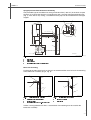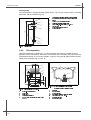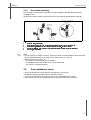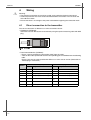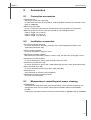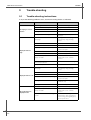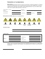
1
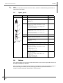
2SHUDWLQJ,QVWUXFWLRQV 226 'LVVROYHGR[\JHQVHQVRU BA285e/00//04.04 51506569 %ULHIRYHUYLHZ Here is how to use these Operating Instructions to commission your sensor quickly and safely: Safety instructions Page 4 ff. Page 5 General safety instructions Explanation of the warning symbols You can find special instructions at the appropriate position in the chapter in question. The positions are indicated with the icons Warning , Caution and Note . d Installation Page 7 ff. Page 10 ff. Here you can find installation conditions such as sensor dimensions and the angle of installation. Installation examples can be found here. d Wiring Page 14 ff. Refer to theses pages for sensor wiring. d Sensor design and measuring principle Page 16 Page 17 ff. Page 17 ff. Here you can read about the sensor design. The measuring principle is explained on this page. Here you can find the possible calibration methods. d Commissioning Page 20 ff. The sensor must be polarised before calibration. Please, read on the given page how to do it. d Maintenance Page 22 ff. Page 23 ff. Page 28 It is absolutely essential to carry out maintenance tasks on a regular basis. Individual parts are subject to normal wear and tear. Here you can find out how to replace such parts. Here you can find an overview of the spare parts which can be delivered as well as an overview of the system. d Trouble-shooting Page 26 ff. If faults occur during operation, use the checklist to locate the cause. d d Index Page 32 ff. You can find important terms and keywords on the individual sections here. Use the keyword index to find the information you need quickly and efficiently. 226 7DEOHRIFRQWHQWV 6DIHW\LQVWUXFWLRQV 1.1 1.2 1.3 1.4 1.5 Designated use . . . . . . . . . . . . . . . . . . . . . Installation, commissioning and operation . Operational safety . . . . . . . . . . . . . . . . . . . Return . . . . . . . . . . . . . . . . . . . . . . . . . . . . Notes on safety icons and symbols . . . . . . ,GHQWLILFDWLRQ 2.1 2.2 Product structure . . . . . . . . . . . . . . . . . . . . 6 Scope of delivery . . . . . . . . . . . . . . . . . . . . 6 ,QVWDOODWLRQ 3.1 3.2 3.3 3.4 3.5 Incoming acceptance, transport, storage . . 7 Installation conditions . . . . . . . . . . . . . . . . 7 Installation instructions . . . . . . . . . . . . . . . 8 Installation examples . . . . . . . . . . . . . . . . 10 Post-installation check . . . . . . . . . . . . . . . 13 :LULQJ 4.1 4.2 4.3 Direct connection to the transmitter . . . . . 14 Connection via junction box . . . . . . . . . . . 15 Post-connection check . . . . . . . . . . . . . . . 15 2SHUDWLRQ 5.1 5.2 5.3 Sensor design . . . . . . . . . . . . . . . . . . . . . 16 Measuring principle . . . . . . . . . . . . . . . . . 17 Calibration . . . . . . . . . . . . . . . . . . . . . . . . 17 &RPPLVVLRQLQJ 6.1 6.2 6.3 Function check . . . . . . . . . . . . . . . . . . . . . 20 Polarisation . . . . . . . . . . . . . . . . . . . . . . . 20 Calibrate . . . . . . . . . . . . . . . . . . . . . . . . . 21 0DLQWHQDQFH 7.1 7.2 Cleaning the sensor . . . . . . . . . . . . . . . . . 22 Regenerating the sensor . . . . . . . . . . . . . 23 $FFHVVRULHV 8.1 8.2 8.3 Connection accessories . . . . . . . . . . . . . . 25 Installation accessories . . . . . . . . . . . . . . 25 Measurement, controlling and sensor cleaning 25 7URXEOHVKRRWLQJ 9.1 9.2 Trouble-shooting instructions . . . . . . . . . . 26 Sensor checks . . . . . . . . . . . . . . . . . . . . . 27 4 4 4 4 5 9.3 9.4 9.5 Spare parts . . . . . . . . . . . . . . . . . . . . . . . . 28 Return . . . . . . . . . . . . . . . . . . . . . . . . . . . . 28 Disposal . . . . . . . . . . . . . . . . . . . . . . . . . . 29 7HFKQLFDOGDWD 10.1 10.2 10.3 10.4 10.5 Input . . . . . . . . . . . . . . . . . . . . . . . . . . . . . Performance characteristics . . . . . . . . . . . Environment . . . . . . . . . . . . . . . . . . . . . . . Process . . . . . . . . . . . . . . . . . . . . . . . . . . Mechanical construction . . . . . . . . . . . . . . 30 30 30 30 31 ,QGH[ 6DIHW\LQVWUXFWLRQV 226 6DIHW\LQVWUXFWLRQV 'HVLJQDWHGXVH The oxygen sensor is suitable for continuous measurement of dissolved oxygen in water. Typical applications are: • Measuring oxygen content in activated sludge basins. The measuring signal is used for monitoring and as a control parameter. • Checking oxygen content in the outlet of a sewage treatment plant. • Measuring and controlling the oxygen content in fish farming water. • Oxygen enrichment in drinking water. Any other use than the one described here compromises the safety of persons and the entire measuring system and is, therefore, not permitted. The manufacturer is not liable for damage caused by improper or non-designated use. ,QVWDOODWLRQFRPPLVVLRQLQJDQGRSHUDWLRQ Please note the following items: • Installation, electrical connection, commissioning, operation and maintenance of the measuring system must only be carried out by trained technical personnel. The technical personnel must be authorised for the specified activities by the system operator. • Technical personnel must have read and understood these Operating Instructions and must adhere to them. • Before commissioning the entire measuring point, check all the connections for correctness. Ensure that electrical cables and hose connections are not damaged. • Do not operate damaged products and secure them against unintentional commissioning. Mark the damaged product as being defective. • Measuring point faults may only be rectified by authorised and specially trained personnel. • If faults can not be rectified, the products must be taken out of service and secured against unintentional commissioning. • Repairs not described in these Operating Instructions may only be carried out at the manufacturer’s or by the service organisation. 2SHUDWLRQDOVDIHW\ The sensor has been designed and tested according to the state of the art and left the factory in perfect functioning order. Relevant regulations and European standards have been met. As the user, you are responsible for complying with the following safety conditions: • Installation instructions • Local prevailing standards and regulations. 5HWXUQ If the device requires repair, please send it FOHDQHG to the sales centre responsible. Please use the original packaging, if possible. Please enclose the completed "Declaration of contamination" (copy the second last page of these Operating Instructions) with the packaging and the transportation documents. No repair without completed "Declaration of contamination"! 226 6DIHW\LQVWUXFWLRQV 1RWHVRQVDIHW\LFRQVDQGV\PEROV Warning! This symbol alerts you to hazards. They can cause serious damage to the instrument or to persons if ignored. Caution! This symbol alerts you to possible faults which could arise from incorrect operation. They could cause damage to the instrument if ignored. Note! This symbol indicates important items of information. ,GHQWLILFDWLRQ 226 ,GHQWLILFDWLRQ 3URGXFWVWUXFWXUH Certificate A Ex free version Cable length 0 Cable length: 1.5 m (4.92 ft) 2 Cable length: 7 m (22.97 ft) 4 Cable length: 15 m (49.22 ft) 8 Without Cable (TOP 68 version only) 9 Special design to customer specifications Cable connection F Fixed cable connection S Cable connection using TOP 68 plug Membrane cap 1 OOY31-WP membrane cap, minimum flow rate 5 mm/s, for normal response time 2 OOY31-S-WP membrane cap, minimum flow rate 25 mm/s, for fast response time OOS31- Complete order code 6FRSHRIGHOLYHU\ The following items are included in the delivery: • Oxygen sensor with transport protection cap for membrane protection • Accessories Set with the following contents: – 2 replacement cartridges (replacement membrane caps) – 10 plastic ampoules containing electrolyte – 1 sealing kit with 3 O-rings – 6 abrasive sheets • Operating Instructions english If you have any questions, please contact your supplier or your sales centre responsible . 226 ,QVWDOODWLRQ ,QVWDOODWLRQ ,QFRPLQJDFFHSWDQFHWUDQVSRUWVWRUDJH Ø40 / 1.57 144 / 5.67 mm / inch Ø40 / 1.57 C07-OOS41xxx-06-05-00-en-001.eps )LJ )L[HGFDEOHYHUVLRQ 190 / 7.48 'LPHQVLRQV 190 / 7.48 171 / 6.73 ,QVWDOODWLRQFRQGLWLRQV 144 / 5.67 171 / 6.73 • Make sure the packaging is undamaged! Inform the supplier about damage to the packaging. Keep the damaged packaging until the matter has been settled. • Make sure the contents are undamaged! Inform the supplier about damage to the delivery contents. Keep the damaged products until the matter has been settled. • Check that the scope of delivery is complete and agrees with your order and the shipping documents. • The packaging material used to store or to transport the product must provide shock protection and humidity protection. The original packaging offers the best protection. Also, keep to the approved ambient conditions (see "Technical data"). • If you have any questions, please contact your supplier or your sales centre responsible. mm / inch C07-OOS41xxx-06-05-00-en-002.eps )LJ 723SOXJLQKHDGYHUVLRQ ,QVWDOODWLRQ 226 $QJOHRILQVWDOODWLRQ The sensor can be installed up to the horizontal in an assembly, support or a suitable process connection (Fig. 3). Other angles are not permissible. Do not install the sensor overhead. A C07-OOS41xxx-11-05-00-xx-001.eps )LJ $ $QJOHRILQVWDOODWLRQ 3HUPLVVLEOHLQVWDOODWLRQSRVLWLRQVRYHUKHDGLQVWDOODWLRQLVQRWSHUPLWWHG Note! Make sure you comply with the instructions for installing sensors. You will find them in the Operating Instructions for the assembly used. ,QVWDOODWLRQSODFH • Select the installation location so that there is easy access for later calibration. • Make sure that upright posts and assemblies are secured safely and vibration-free. • For immersed operation in an activated sludge basin, select an installation location which produces a typical oxygen concentration. ,QVWDOODWLRQLQVWUXFWLRQV 0HDVXULQJV\VWHP A complete measuring system comprises at least: • Oxygen sensor • Transmitter, e.g. OOM223/253 • Special measuring cable • Assembly, e.g. flow assembly OOA250, immersion assembly OOA110 or retractable assembly OOA451 Optional: • Universal suspension assembly support OOH 101 for immersed operation • Junction box VS (with cable extension) • Automatic spray cleaning system 226 ,QVWDOODWLRQ 1 2 4 3 C07-OOS71xxx-14-05-00-xx-001.eps )LJ 0HDVXULQJV\VWHPH[DPSOH )ORZDVVHPEO\ -XQFWLRQER[96RSWLRQDO 7UDQVPLWWHU220 2[\JHQVHQVRU ,QVWDOOLQJDPHDVXULQJSRLQW Note! For immersed operation, install the individual modules away from the basin on a solid base. Only carry out the final installation at the intended installation location. For a complete installation of a measuring point, proceed as follows: 1. Install a retractable or a flow assembly (if used) into the process. 2. Connect the water supply to the rinse connections (if you use an assembly with cleaning function). 3. Install and connect the oxygen sensor. 4. Install an immersion or an suspension assembly (if used) into the process. Caution! • For immersed operation, the sensor must be installed in an immersion assembly (e.g. OYA 611). Do not install the sensor suspended from the cable. • Screw the sensor into the assembly so that the cable is not twisted. • Avoid exerting excessive tensile force on the cable (e.g. from jerky pulling). • Select the installation location so that there is easy access for later calibration. Warning! When using metallic assemblies and installation equipment, comply with national grounding regulations. ,QVWDOODWLRQ 226 ,QVWDOODWLRQH[DPSOHV ,PPHUVLRQRSHUDWLRQ 8SULJKWSRVWDQGFKDLQDVVHPEO\ For large basins, where sufficient installation distance is required from the basin edge (aeration basin, especially), it is advisable to use the upright post and chain assembly (Fig. 5, Fig. 6). The free swinging of the immersed assembly practically rules out vibrations from the upright post. A good self-cleaning of the membrane surface is reached due to the swinging of the assembly. According to this effect, the sensor life time can be extended. 56/2.20 1 1 3 5 25/0.98 4 60/2.36 120/4.72 22/0.87 6 6/0.24 58/2.58 Ø 40/1.57 Ø 6,5/0.26 Ø 14/0.55 4 450/17.72 950/37.40 1480/58.27 2 Ø 40/1.57 1500/59.06 max. 1400/55.12 1630/64.17 3 1580/64.20 2 Ø 35/1.38 x 1.5/0.06 60/2.36 x 60/2.36 x 2/0.08 4 12 xØ 2 .4 /0 150/5.91 mm/inch Ø 48/1.89 mm/inch 5 C07-OOS41xxx-11-05-00-en-002.eps )LJ 8QLYHUVDOVXVSHQVLRQDVVHPEO\KROGHU ZLWKLPPHUVLEOHSHQGXOXPDVVHPEO\ :HDWKHUSURWHFWLRQFRYHU 8SULJKWSRVWVTXDUHSLSH66$,6, 7UDQVYHUVHSLSH66$,6, 6WDUKDQGOH 6HFRQGIL[LQJSRVVLELOLW\IRUWUDQVYHUVHSLSH ,PPHUVLRQDVVHPEO\2<$ C07-OOS41xxx-11-05-00-en-004.eps )LJ ,PPHUVLRQDVVHPEO\2<$ 3URWHFWLRQFDS :RUPGULYHKRVHFOLS 3LSHFOLSVGHWDLOHGGUDZLQJLQULJKWKDOI 39&SLSH 7KUHDGHGFRXSOLQJ 226 ,QVWDOODWLRQ 8SULJKWSRVWDQGIL[HGLPPHUVLRQDVVHPEO\ The preferable type of installation for strong or turbulent flow (> 0.5 m/s) in the basin or open channels is to secure the device to an upright post and a securely mounted immersion tube (Fig. 7). If the flow is very strong, a second transverse pipe can be installed with its own pipe support. 2 1 3 1500/59.06 1 max. 1400/55.12 1490/58.66 2000/78.74 (3500/137.80) Ø 40/1.57 450/17.72 950/37.40 4 30/1.18 x 30/1.18 x 2/0.06 120/4.72 4 4 x Ø 12/0.42 150/5.91 mm/inch C07-OOS41xxx-11-05-00-en-003.eps )LJ 8QLYHUVDOVXVSHQVLRQDVVHPEO\KROGHUZLWKLPPHUVLRQDVVHPEO\ 6WDUKDQGOH 3LSHKROGHU )L[LQJEUDFNHW ,PPHUVLRQDVVHPEO\ LPPHUVLRQWXEH %DVLQULPPRXQWLQJ For fixing to the sides of the basin or channel, we recommend the use of an basin rim mounting of the immersion assembly (Fig. 8, Fig. 9). 5 1 1 5 2 2 4 4 3 3 C07-OOS41xxx-11-05-00-xx-005.eps )LJ +RUL]RQWDOEDVLQULPPRXQWLQJ 3URWHFWLRQFRYHUIRUFDEOHHQWU\ $VVHPEO\KROGHU ,PPHUVLRQDVVHPEO\66$,6, C07-OOS41xxx-11-05-00-xx-006.eps )LJ 9HUWLFDOEDVLQULPPRXQWLQJ %DVLQULPPRXQWLQJ 6WDUKDQGOH If there is strong turbulence or flow, a second basin rim mounting must be used for the immersion assembly. ,QVWDOODWLRQ 226 )ORDWLQJERG\ To aid installation in strongly fluctuating water levels, e.g. in rivers or lakes, there is a floating body OOA 110-50 available (Fig. 10). 1 2 220 3 Ø200 &DEOHURXWHZLWKVWUDLQUHOLHIDQGUDLQSURWHFWLRQ 0RXQWLQJULQJIRUURSHVDQGFKDLQVZLWKORFNLQJ VFUHZ /XJV[IRUDQFKRULQJ 6DOWZDWHUUHVLVWDQWSODVWLFIORDW 3LSH[UXVWSURRIVWHHO66 $,6, 7L 6KRFNDEVRUEHUDQGZHLJKW 2[\JHQVHQVRU 500 800 4 G1 5 6 7 &226[[[GHHSV )LJ )ORDWLQJERG\ )ORZRSHUDWLRQ The OOA 250-A flow assembly (Fig. 11) with automatic self-venting is suitable for use in pipelines or hose connections. The inlet is at the bottom of the assembly, the outlet at the top (connection thread G ¾). It can be installed in a pipe by using two 90° pipe brackets to allow inflow to the assembly (Fig. 12, Pos. 6). mm/inch 1 1 G¾ 3 196/7.72 Ø34/1.34 2 8 3 2 68/2.68 G¾ 4 2.5/0.10 Ø34/1.34 23/0.91 7 90/3.54 100/3.94 5 C07-OOS41xxx-11-05-00-de-008.eps )LJ )ORZDVVHPEO\22$$ 6FUHZLQSDUWIRUVHQVRU 6FUHZULQJ 0HWHUERG\ &RQQHFWLRQWKUHDG*ô 'XPP\SOXJFRQQHFWLRQIRUVSUD\KHDG &25 6 5 4 C07-OOS41xxx-11-05-00-xx-009.eps )LJ %\SDVVLQVWDOODWLRQZLWKPDQXDOO\ DFWXDWHGYDOYHVRUVROHQRLGYDOYHV 0DLQOLQH 0HGLXPUHWXUQ 2[\JHQVHQVRU 0DQXDOO\DFWXDWHGRUVROHQRLGYDOYHV )ORZDVVHPEO\22$$ SLSHEUDFNHW 0HGLXPUHPRYDO 226 ,QVWDOODWLRQ 5HWUDFWDEOHDVVHPEO\ The assembly is designed for installation on tanks and pipes. Suitable nozzles must be available for this. Install the assembly at places with constant flow. The minimum pipe diameter is DN 80. Detail A, rotated 90° (side view) 2 Detail A, (top view) 3 3 1 4 5 C07-OOA451xx-11-07-00-en-001.eps )LJ 3HUPLVVLEOHDQGLPSHUPLVVLEOHVHQVRULQVWDOODWLRQSRVLWLRQV $VFHQGLQJSLSHEHVWSRVLWLRQ +RUL]RQWDOSLSHVHQVRUWRSGRZQLPSHUPLVVLEOHGXHWRDLUFXVKLRQRUIRDPEXEEOHIRUPLQJ +RUL]RQWDOSLSHLQVWDOODWLRQZLWKSHUPLVVLEOHHPLWWLQJDQJOHVDFFWRVHQVRUYHUVLRQ 2YHUKHDGLQVWDOODWLRQLPSHUPLVVLEOHGXHWRPLVVLQJHOHFWURO\WHFRQWDFWRIWKHVHQVRUHOHFWURGHV 'RZQSLSHLPSHUPLVVLEOH Note! • Do not install the assembly at places, where air cushions or foam bubbles can be formed or where suspended particles can settle on the sensor optics (→ Fig. 13). • Measuring errors can occur, if: – the sensor is not immersed into the medium – suspended particles are settled on the sensor membrane – the sensor is installed overhead. • • • • 3RVWLQVWDOODWLRQFKHFN Check the membrane for leak tighness und replace it if necessary. Compliance with permissible sensor installation position? Is the sensor installed to an assembly and is not suspended from the cable? Avoid moisture by rain by fitting the protective cap to the immersion assembly? :LULQJ 226 :LULQJ Warning! • The electrical connection must only be carried out by authorised technical personnel. • Technical personnel must have read and understood the instructions in this manual and must adhere to them. • Ensure that there is no voltage at the power cable before beginning the connection work. 'LUHFWFRQQHFWLRQWRWKHWUDQVPLWWHU The sensor connection is different acc. to the transmitter version: • Field device (OOM253): Connect the sensor directly to the transmitter by using the special measuring cable with SXP plug. C07-OOS41xxx-04-05-00-xx-001.eps )LJ 6;3SOXJ • Panel mounted device (OOM223): – Please, remove the SXP plug (transmitter side!) from the cable. – Take out the cable specification and the corresponding pins of OOM223 from the following table. Please note, that the cable specification differs acc. to the sensor version (fixed cable or TOP68 plug-in connection). Pin of OOM223 Sensor with fixed cable (OMK) Sensor with TOP68 plug-in head (CYK71) Colour Assignment Colour Assignment 87 yellow +UB yellow +UB 0 grey OV white OV 96 pink NTC (analogue) or comm. (digital) green Communication (digital) 97 blue NTC (analogue) or comm. (digital) brown Communication (digital) 88 brown –UB 19 green Alarm 18 white Sensor signal COAx inner –UB 226 :LULQJ &RQQHFWLRQYLDMXQFWLRQER[ To lengthen the sensor connection beyond the length of the fixed cable, you require a junction box VS (Fig. 15, Fig. 16). Always connect the sensor cable with the SXP plug to the junction box. The cable extension to the transmitter then depends from the transmitter version, i.e. field device or panel mounted device. 1 82 80 4 YE GY PK BU BN 2 3 2 GN WH 87 0 96 97 88 19 18 C07-OOS31xxx-04-05-00-xx-002.eps C07-OOS31xxx-04-05-00-de-001.eps )LJ -XQFWLRQER[96WRDILHOGGHYLFH 6;3SOXJWRILHOGGHYLFH 6;3SOXJIURPVHQVRU )LJ -XQFWLRQER[96WRDSDQHOPRXQWHGGHYLFH 6;3SOXJIURPVHQVRU 0HDVXULQJFDEOH20.WRWKHWUDQVPLWWHU &RQQHFWLRQGHSDUWPHQWRIWKHWUDQVPLWWHU 3RVWFRQQHFWLRQFKHFN Instrument status and specifications Remarks Are the sensor, assembly, junction box or cable damaged? Visual inspection Electrical connection Remarks Does the supply voltage of the transmitter match the specifications on the nameplate? 110/230 V AC 24 V AC/DC Are the installed cables strain-relieved and not twisted ? Is the cable type route completely isolated ? Power cable/weak current cable Are the power supply and signal cable correctly connected to the transmitter ? Use the connection diagram of OOM 2x3. Are all the screws terminals properly tightened ? Are all the cable entries installed, tightened and sealed ? Are all the cable entries installed downwards or lateral ? For cable entries lateral: cable loops downwards for water to be able to drip off. 2SHUDWLRQ 226 2SHUDWLRQ 6HQVRUGHVLJQ 1 10 11 3 9 12 8 13 7 C07-OOS41xxx-16-05-07-xx-001.eps )LJ 6HQVRUKHDGFXWDZD\GUDZLQJ 4 9 5 0HPEUDQH (OHFWURO\WH $QRGH 7KUHDGHGFRQQHFWLRQIRUSURWHFWLRQEDVNHW 6HDOLQJULQJ 7KUHDGHGFRQQHFWLRQIRUPHPEUDQHFDS 0HPEUDQHFDS 8 7 6 6 C07-OOS371xx-03-05-00-xx-001.eps )LJ 6HQVRUGHVLJQ 6HQVRUFDEOH 7KUHDGHGFRQQHFWLRQ* 6HQVRUVKDIW 3URWHFWLRQEDVNHW &DWKRGH 0HPEUDQH (OHFWURO\WH $QRGH C07-OOS41xxx-16-05-03-xx-002.eps )LJ 6HQVRUKHDGWRSYLHZ &DWKRGH The sensor consists of the following function units: • Sensor shaft (Fig. 17, pos. 4) • Sensor head with cathode and anode (Fig. 18, Fig. 19) • Membrane cap with electrolyte filling (Fig. 18, pos. 13 and 8) • Protection basket (Fig. 17, pos. 5) Note! • Alternatively to the protection basket, you can use a spray head OOR 3 (optional, see "Accessories") for use in immersed operation with cleaning function. • The membrane cap screwed onto the sensor head is filled with electrolyte. The screw connection seals it from the medium. • The membrane which is in contact with the medium is pretensioned in the factory. 226 2SHUDWLRQ 0HDVXULQJSULQFLSOH 3RODULVDWLRQ When the sensor is connected to the transmitter, a fixed external voltage is applied between the cathode and anode. The resulting polarisation current is indicated on a display on the transmitter. The current starts high but then drops over time. The sensor can only be calibrated when the display is stable. 0HPEUDQH The oxygen dissolved in the medium is conveyed to the membrane by the incoming flow. The membrane is only permeable for dissolved gases. Other substances dissolved in the liquid phase e.g. ionic substances, will not penetrate through the membrane. Therefore, medium conductivity has no impact on the measuring signal. $PSHURPHWULFSULQFLSOH The oxygen molecules diffused through the membrane are reduced to hydroxide ions (OH-) at the cathode. Silver is oxidised to silver ions (Ag+) at the anode (this forms a silver bromide layer, AgBr). A current flows due to the connected electrode release at the cathode and accepted at the anode. In equilibrium, this flow is proportional to the oxygen content of the medium. This current is converted in the measuring instrument and indicated on the display as an oxygen concentration in mg/l, as a saturation index in % SAT or as an oxygen partial pressure in hPa. &DOLEUDWLRQ Calibration is a means of adapting the transmitter to the characteristic values of the sensor. As no zero calibration is required for the sensor, a single-point calibration is carried out in the presence of oxygen. The sensor requires calibration after: • first commissioning • replacing a membrane or electrolyte • cleaning the cathode • long breaks in operation without power supply • typical time intervals dependent on operating experience There are three basic types of calibration: • in air (preferably saturated water vapour, e.g. near the water surface) • in air-saturated water • by entering a reference measured value in the transmitter (sensor remains in the medium). Note! Following only the calibration in air is discribed because it is the easiest and that’s why the recommended method of calibration. Calibration in air is only possible if air temperature ≥ – 5 °C. 2SHUDWLRQ 226 &DOLEUDWLRQLQDLU 1. Remove the sensor from the medium. 2. Clean the outside of the sensor with a damp cloth. Then dry the sensor membrane e.g. by using a tissue. 3. If the sensor is removed from a closed pressure system with a process pressure greater than atmospheric pressure: – Open the membrane cap to equilibrate the pressure and clean the cap if necessary. – Replace the electrolyte filling and close the membrane cap again. – Wait for the polarisation time to end. 4. Then wait while the sensor adjusts to the temperature of the ambient air. This takes about 20 minutes. Check that the sensor is not in direct sunlight during this time. 5. If the measured value display on the transmitter is stable, carry out the calibration in accordance with the Operating Instructions of the transmitter. 6. Place the sensor in the medium again. Note! Make sure you comply with the instructions for calibration in the Operating Instructions of the transmitter. &DOFXODWLRQH[DPSOHIRUWKHFDOLEUDWLRQYDOXH As a check, you can calculate the expected calibration value (transmitter display) as shown in the following example (salinity is 0). 1. Determine: – the sensor temperature (ambient air) – the altitude above sea level – the current air pressure (=rel. air pressure to sea level) at the time of calibration. (If undeterminable, use 1013 hPa for an approximate calculation.) 2. Define: – the saturation value S acc. to the first table – the factor K acc. to the second table °C S [mg/l] °C S [mg/l] °C S [mg/l] °C S [mg/l] 0 14.64 11 10.99 21 8.90 31 7.42 1 14.23 12 10.75 22 8.73 32 7.30 2 13.83 13 10.51 23 8.57 33 7.18 3 13.45 14 10.28 24 8.41 34 7.06 4 13.09 15 10.06 25 8.25 35 6.94 5 12.75 16 9.85 26 8.11 36 6.83 6 12.42 17 9.64 27 7.96 37 6.72 7 12.11 18 9.45 28 7.82 38 6.61 8 11.81 19 9.26 29 7.69 39 6.51 9 11.53 20 9.08 30 7.55 40 6.41 10 11.25 226 2SHUDWLRQ Altitude [m] K Altitude [m] K Altitude [m] K Altitude [m] K 0 1.000 550 0.938 1050 0.885 1550 0.834 50 0.994 600 0.932 1100 0.879 1600 0.830 100 0.988 650 0.927 1150 0.874 1650 0.825 150 0.982 700 0.922 1200 0.869 1700 0.820 200 0.977 750 0.916 1250 0.864 1750 0.815 250 0.971 800 0.911 1300 0.859 1800 0.810 300 0.966 850 0.905 1350 0.854 1850 0.805 350 0.960 900 0.900 1400 0.849 1900 0.801 400 0.954 950 0.895 1450 0.844 1950 0.796 450 0.949 1000 0.890 1500 0.839 2000 0.792 500 0.943 3. Determine: – L = rel. air pressure at calibration (1013 hPa if unknown) – M = 1.02 for calibration in air resp. 1.00 for calibration in air-saturated water 4. Calculate the calibration value C: C=S.K.L.M Example • Air calibration at 18°C, altitude 500 m above sea level, air pressure 1022 hPa • S = 9.45 mg/l, K = 0.943, L = 1.0089, M = 1.02 Calibration value C = 9.17 mg/l. &RPPLVVLRQLQJ 226 &RPPLVVLRQLQJ )XQFWLRQFKHFN Before first commissioning, check if: • the sensor is correctly installed • the electrical connection is correct. If using an assembly with automatic cleaning, check the correct water connection at the assembly rinse connection. Warning! Danger of medium leaking off Before applying compressed air to an assembly with cleaning facility, make sure the connections are correctly fitted. Otherwise, the assembly may not be insert into the process. 3RODULVDWLRQ The sensor was tested in the factory for perfect functionality and is supplied ready for operation. To prepare for calibration, proceed as follows: 1. Remove the sensor protective cap. 2. Place the externally dry sensor in atmospheric air. The air should be saturated with water vapour. Therefore, install the sensor as close to the water surface as possible. When calibrating the sensor membrane, make sure the membrane remains dry. Therefore, avoid any direct contact with the water surface. 3. Connect the sensor to the transmitter and switch on the transmitter. 4. Switch-on the transmitter. If you connect the sensor to the transmitter OOM223/253, polarisation is automatically performed after switching on the transmitter. 5. The polarisation time takes about 1 hour. Note! Polarisation starts high, then drops gradually. You will recognise the end of polarisation when the display stabilises and remains practically constant. Caution! • When you remove the sensor from the medium, protect the sensor from strong sunlight. • Make sure you comply with the instructions for commissioning and calibration in the Operating Instructions of the transmitter. 226 &RPPLVVLRQLQJ &DOLEUDWH Calibrate the sensor (Calibration in air, → Page 18) immediately after it’s polarisation. The calibration intervals depend heavily on: • The application and • The installation position of the sensor. The following methods help you determine how long the calibration intervals should be: 1. Check the sensor one month after its being put into operation by taking it out of the fluid, drying it and then measuring the oxygen saturation index at air after 10 minutes. Decide using the results: a. If the measured value is not at 102 ±2 %SAT, you have to calibrate the sensor. b. Otherwise, double the length of time to the next inspection. 2. Proceed as per Point 1 after two, four and/or eight months. In this way, you can determine the optimum calibration interval for your sensor. Note! Be sure to calibrate the sensor at least once a year. 0DLQWHQDQFH 226 0DLQWHQDQFH Maintenance work must carried out at regular intervals. To ensure that it is carried out, we recommend you enter the maintenance dates into an operations logbook or in an operations calendar in advance. The following activities must be carried out: • Cleaning the sensor (In particular when the membrane is soiled) • Check the measuring function: 1. Remove the sensor from the medium. 2. Clean and dry the membrane. 3. After about 10 minutes, measure the oxygen saturation index in air (without recalibration). 4. The measured value should be near to 102% SAT (display of O2 saturation with OOM 2x3 by pressing 4 times the . key). • Replace a defective membrane or one which cannot be cleaned any more. • Recalibration. Note! For regular automatic sensor cleaning, we recommend equipping the measuring point with a fully-automatic cleaning system. &OHDQLQJWKHVHQVRU The measurement can be corrupted by sensor fouling or malfunction, e.g.: • Coatings on the sensor membrane ➠ cause longer response times and a reduced slope. • Soiling or poisoning of the electrolyte ➠ causes longer response times and false measurement. To ensure reliable measurement, the sensor must be cleaned at regular intervals. The frequency and intensity of the cleaning operation depend on the measuring medium. Clean the sensor: • before every calibration • at regular intervals during operation as necessary • before returning it for repairs. Depending on the type of soiling, proceed as follows: Type of soiling Cleaning Salt deposits Immerse the sensor in drinking water or in 1-5% hydrochloric acid for a few minutes. Afterwards, rinse it with copious amounts of water. Dirt particles on the sensor body (not on the membrane!) Clean the sensor body mechanically with water and a suitable brush. Dirt particles on the membrane cap or the membrane Clean the membrane with water and a soft sponge. Caution! After cleaning, rinse the sensor with copious amounts of clean water. 226 0DLQWHQDQFH 5HJHQHUDWLQJWKHVHQVRU Parts of the sensor will suffer wear and tear during operation. Suitable action can restore normal operating functionality. This action includes: Action Cause Cleaning the cathode soiled or plated cathode Replacing the sealing ring visual damage to the sealing ring Replacing the electrolyte unstable or implausible measuring signal or electrolyte soiling Replacing the membrane cap uncleanable membrane, damaged membrane (hole or overstretch) Warning! Before beginning regeneration, switch off the power supply at the transmitter. &OHDQLQJWKHFDWKRGH The cathode only needs to be cleaned when it is visibly soiled or there is a Coating of silver on it. To clean it, proceed as follows: 1. Unscrew the membrane cap from the membrane body. 2. Carefully clean the surface in two stages with the abrasive sheet (contained in scope of supply) until the (silver) Coating is fully removed. Use the green sheet first and then the yellow sheet. 3. Clean the electrode with drinking or distilled water. 4. Fill the membrane cap with fresh electrolyte OOY 3-F and screw it back onto the membrane body (up to the stop). Caution! The anode is covered with a silver bromide layer at the factory. Do not clean the anode under any circumstances! If the Coating of the anode is removed as a result of operation, the sensor is unusable and must be sent in for recoating. In this case, contact your sales office. 5HSODFLQJWKHVHDOLQJULQJ Replacing the sealing ring is only necessary when it is visibly damaged. For replacement, use only the supplied sealing rings OOY 31-OR. 5HSODFLQJWKHHOHFWURO\WH The electrolyte OOY 3-F is slowly used up during measuring operations. The cause of this is electrochemical substance reactions. No substance reactions occur in de-energised state and the electrolyte is not used up. The theoretical life of an electrolyte filling for use in air-saturated drinking water at 20°C is max. 5 years. The electrolyte life is shortened by diffused, dissolved gases such as H2S, NH3 or high concentrations of CO2. Particular loads occur with: • anaerobic stages (e.g. denitrification) • strongly polluted industrial wastewater, particularly at high temperatures. 0DLQWHQDQFH 226 Warning! Risk of acid burns! The electrolyte is strongly alkaline. You must follow the appropriate occupational safety regulations. Always wear protective gloves and goggles with handling electrolytes. To replace the electrolyte, proceed as follows: 1. Remove the membrane cap. 2. Replace the electrolyte and, if necessary, the membrane cap. 3. Place the membrane cap back on the membrane body and screw the cap to the stop. 5HSODFLQJWKHPHPEUDQHFDS Removing the old membrane cap 1. Remove the sensor from the medium. 2. Unscrew the protection basket. 3. Clean the outside of the sensor. 4. Unscrew the membrane cap. 5. If necessary, clean the cathode or replace the sealing ring if it is damaged. 6. Rinse the electrode holder with drinking water. Installing the new membrane cap 7. Make sure that there are no dirt particles on the sealing surface. 8. Fill the complete contents of a plastic ampoule (containing electrolyte OOY3-F) into the membrane cap. 9. Remove all the air bubbles in the electrolyte by tapping the side of the membrane cap (e.g. with a pencil). 10. Hold the sensor body at an angle and carefully screw the membrane cap onto it down to the stop. 11. Screw the protection basket back on. Note! After replacing the membrane cap, polarise and recalibrate the sensor. Then insert the sensor into the medium and check that no alarm is displayed on the transmitter. 226 $FFHVVRULHV $FFHVVRULHV &RQQHFWLRQDFFHVVRULHV ❑ VS junction box with plug-in socket and 7-pole plug, for cable extension from sensor (OOS 31, OOS 3 with SXP connector) to transmitter, IP 65; order no. 50001054 ❑ Measuring cable OMK for use as extension cable between junction box VS and transmitter, not terminated ❑ Measuring cable for sensors OOS 31 and OOS 71 with TOP 68 connector OOK 31; length: 1.5 m (4.92 ft) OOK 31; length: 7 m (22.97 ft) OOK 31; length: 15 m (49.22 ft) ,QVWDOODWLRQDFFHVVRULHV ❑ Immersion assembly OOA110 for sensor immersion in the basin, PVC pipe resp. PUR floating body with SS 1.4571 (AISI 316Ti) immersion tube; ❑ Flow assembly OOA250 for sensor installation in pipe lines, PVC; ❑ Retractable assembly OOA451 Manually driven retractable assembly, stainless steel, with ball valve, for oxygen sensors; ❑ Immersion assembly OYA611 for sensor immersion in basins, open channels and tanks, PVC; ❑ Immersion assembly OOY 105 for sensor immersion in basins, SS 1.4404 (AISI 316L) pipe, SS 1.4571 (AISI 316Ti) fitting; ❑ Basin rim holder OOY 106 for sensor immersion into the basin, SS 1.4301 (AISI 304); ❑ Baffle plate OP extra protection for extreme current conditions; ❑ Membrane protection basket OOY 3-SK or sensor use in fish ponds; 0HDVXUHPHQWFRQWUROOLQJDQGVHQVRUFOHDQLQJ ❑ OOM223/253 Transmitter with integrated sensor function monitoring, measured value monitoring, free configuration alarm contact, field or control panel installation, HART® or PROFIBUS possible; Ordering acc. to product structure, see Technical Information TI 199e00; order no. 51505694 7URXEOHVKRRWLQJ 226 7URXEOHVKRRWLQJ 7URXEOHVKRRWLQJLQVWUXFWLRQV If any of the following problems occur, test the measuring device as indicated. Problem No display, no sensor reaction Displayed value too high Check Remedial action Mains voltage to the transmitter? Connect mains voltage. Sensor connected correctly? Set up correct connection. Medium flow available? Create flow. Coating on the membrane? Clean the sensor. Electrolyte in the measuring chamber? Fill with electrolyte or replace electrolyte. With a TOP 68 connection: humidity or dirt in plug? Cleaning of the TOP 68 plug-in connection by using cleaning alcohol. Polarisation complete? Wait until polarisation time ends. Last calibration with different sensor? Recalibrate Temperature display clearly too low? Check sensor, if necessary send sensor in for repair. Membrane visibly stretched? Replace membrane cap. Electrolyte soiled? Replace electrolyte. Open sensor. Dry electrodes transmitter display now at 0? Check electrical connection. If the problem still occurs, send the sensor in. Anode coating dissolved, is the anode silver instead of brown? Send in the sensor for recoating. Cathode silver-plated? Clean the cathode. With a TOP 68 connection: Humidity or dirt in plug ? Cleaning of the TOP 68 plug-in connection by using cleaning alcohol. Sensor calibrated? Recalibrate Medium flow available? Create flow. Displayed value too low Displayesd temperature clearly too high? Check sensor, if necessary send sensor in for repair. Strong deviations in displayed value Coating on the membrane? Clean membrane or replace membrane cap. Electrolyte soiled? Replace electrolyte. Membrane visibly stretched? Replace membrane cap. Open sensor. Dry electrodes transmitter display now at 0? Check electrical connection. If the problem still occurs, send the sensor in. EMC interference on the measuring system? Remove outer screening of sensor and extension cable at terminal S. Cut measuring and signalling lines from h.v. power lines. 226 7URXEOHVKRRWLQJ Problem Check Remedial action Membrane no longer sealed due to damage? Replace membrane cap, polarise and calibrate the sensor. Membrane outside-to-outside not damaged? Screw membrane cap tight. If the alarm still occurs: Separate sensor from transmitter for min. 30 seconds. Repeat once or twice, if the alarm remains. If the alarm still occurs: replace membrane cap, polarise and calibrate. Membrane breakage alarm Sealing ring of membrane cap not clean? Take the sensor from the medium, clean and dry it. Clean the sealing ring or replace it, if it is damaged. Separate sensor from transmitter for min. 30 seconds. Repeat once or twice, if the alarm remains. If the alarm still occurs: send sensor in for repair. Note! Make sure you comply with the instructions for troubleshooting in the Operating Instructions of the transmitter. If necessary, carry out a test of the transmitter. 6HQVRUFKHFNV Caution! Only authorised and trained personnel may test the sensor! You will also require a multimeter (voltage, resistance). Check Measure Setpoint Voltage inspection With the sensor connected, test the operating voltage on the OOM 223/253 transmitter between terminals 87 and 0: +8 V between terminals 88 and 0: –8 V Slope inspection Place the sensor in the air, and dry with a paper towel. After 10 minutes: approx. 102% SAT (4 times .) Immerse the sensor in zero solution1. Display near to 0 mg/l (0% Sat) Zero point inspection Temperature sensor check 1 Open the measuring chamber and dry the electrodes. Disconnect the sensor and measure the resistance: – between TOP68 pins 3 and 4 – between SXP pins 3 and 4 (with fixed cable version) depending on temperature: 5 °C: 74.4 kΩ 10 °C: 58.7 kΩ 15 °C: 46.7 kΩ 20 °C: 37.3 kΩ 25 °C: 30.0 kΩ 30 °C: 24.3 kΩ How to use the zero solution: 1. Fill a large beaker (1.5 - 2 l) with approx. 1 l of water. 2. Pour a cap-full of the zero solution into the water. 3. Immerse the sensor into the water and wait a sufficient period of time (15 min. for oxygen depletion). The display drops to around 0 mg/l (0 %SAT). Depending on the conditions (contact surface water/air), the zero solution is stable for up to 12 hours. 7URXEOHVKRRWLQJ 226 Note! If there are deviations from the reference values, follow the troubleshooting instructions or contact your sales office. 6SDUHSDUWV Position Spare parts kit order no. 1 Sensor see product structure 2 Sealing ring OOY31-OR – Material: Viton – 3 pieces on request Membrane cap – Replacement cartridge OOY31-WP for normal response time – 2 preterminated replacement cartridges with pretensioned membrane on request Membrane cap – Replacement cartridge OOY31S-WP for fast response time – 2 preterminated replacement cartridges with pretensioned membrane on request Membrane protection basket on request Electrolyte OOY3-F – 10 plastic ampoules, transparent on request Polishing sheets OOY3-PF – for cathode cleaning – 10 pieces on request Zero solution – 3 units to produce 3 x 1 litre oxygen free solution on request Accessories kit OOY31-Z, one of each: – Electrolyte OOY3F – Replacement cartridge OOY31-WP for normal response time – Sealing ring OOY31-OR – Polishing sheet OOY3-PF on request Accessories kit OOY31-S-Z, one of each: – Electrolyte OOY3F – Replacement cartridge OOY31S-WP for fast response time – Sealing ring OOY31-OR – Polishing sheet OOY3-PF on request 1 2 3 3 4 4 without fig. C07-OOS41xxx-09-05-06-xx-001.eps )LJ 226 2-4 5HWXUQ If the device requires repair, please send it FOHDQHG to the sales centre responsible. Please use the original packaging, if possible. Please enclose the completed "Declaration of contamination" (copy the second last page of these Operating Instructions) with the packaging and the transportation documents. No repair without completed "Declaration of contamination"! 226 7URXEOHVKRRWLQJ 'LVSRVDO The device contains electronic components and must therefore be disposed of in accordance with regulations on the disposal of electronic waste. Please observe local regulations. 7HFKQLFDOGDWD 7HFKQLFDOGDWD ,QSXW Measured value dissolved oxygen [mg/l / % SAT / hPa] Measuring range with OOM223/253: 0.05 ... 60.00 mg/l 0.00 ... 600 % SAT 0 ... 1200 hPa 3HUIRUPDQFHFKDUDFWHULVWLFV Response time • OOS31-XXX1 (membrane cap for normal response time): – T90: 3 minutes – T99: 9 minutes (each at 20 °C) • OOS31-XXX2 (membrane cap for fast response time): – T90: 0.5 minutes – T99: 1.5 minutes (each at 20 °C) Slope approx. 300 nA (at 20 °C, 1013 hPa) Polarisation time < 60 minutes Minimum flow rate for 95 % of measured value display: • OOS31-XXX1: typical 0.5 cm/s • OOS31-XXX2: typical 2.5 cm/s Drift with permanent polarisation: < 1 % per month Zero current zero current free Sensor monitoring with OOM 223/253: cable interruption or short-circuit incorrect measurement and sensor passivation (QYLURQPHQW Storage temperature filled with electrolyte: –5 ... 50 °C (23 ... 122 °F) without electrolyte: –20 ... 60 °C (–4 ... 140 °F) Ingress protection IP 68 226 3URFHVV Process pressure max. 10 bar (145 psi) permissible overpressure Underpressure operation is not permissible. Process temperature –5 ... 50 °C (23 ... 122 °F) 226 7HFKQLFDOGDWD 0HFKDQLFDOFRQVWUXFWLRQ Design, dimensions see chapter "Installation" Weights with cable length 7 m (22.97 ft): 0.7 kg (1.5 lb.) with cable length 15 m (49.22 ft): 1.1 kg (2.4 lb.) with TOP68 plug-in connection: 0.3 kg (0.7 lb.) Materials Sensor shaft: Membrane cap: Cathode: Anode: Process connections G1 Cable entry (sensor) Fixed cable or TOP68 plug-in connection Cable entry (transmitter) • SXP plug (field device) • Terminal connection (panel mounted device) Cable length incl. extension cable max. 100 m / 328.1 ft (including cable extension) Temperature compensation NTC temperature sensor 30 kΩ at 25 °C (77 °F), 0 ... 50 °C (32 ... 122 °F) Membrane thickness • OOS31-XXX1: approx. 50 µm • OOS31-XXX2: approx. 25 µm stainless steel 1.4571, AISI 316Ti POM Gold Silver / Silver bromide 226 ,QGH[ $ Flow operation . . . . . . . . . . . . . . . . . . . . . . . . . . . 12 Accessories Baffle plate . . . . . . . . . . . . . . . . . . . . . . . . . . . 25 For cleaning . . . . . . . . . . . . . . . . . . . . . . . . . . 25 For connection . . . . . . . . . . . . . . . . . . . . . . . . 25 For installation . . . . . . . . . . . . . . . . . . . . . . . . 25 Measurement, controlling and cleaning . . . . . 25 Membrane protection basket . . . . . . . . . . . . . 25 Amperometric principle . . . . . . . . . . . . . . . . . . . . 17 Angle of installation . . . . . . . . . . . . . . . . . . . . . . . . 8 , % Baffle plate . . . . . . . . . . . . . . . . . . . . . . . . . . . . . 25 Basin rim holder . . . . . . . . . . . . . . . . . . . . . . . . . 11 & Cable connection . . . . . . . . . . . . . . . . . . . . . . . . 31 Cable length . . . . . . . . . . . . . . . . . . . . . . . . . . . . 31 Calibration . . . . . . . . . . . . . . . . . . . . . . . . . . . . . . 21 Calculating the calibration value . . . . . . . . . . 18 General . . . . . . . . . . . . . . . . . . . . . . . . . . . . . 17 In air . . . . . . . . . . . . . . . . . . . . . . . . . . . . . . . . 18 Chain assembly. . . . . . . . . . . . . . . . . . . . . . . . . . 10 Checking Connection. . . . . . . . . . . . . . . . . . . . . . . . . . . 15 Function . . . . . . . . . . . . . . . . . . . . . . . . . . . . . 20 Installation . . . . . . . . . . . . . . . . . . . . . . . . . . . 13 Cleaning Gold cathode . . . . . . . . . . . . . . . . . . . . . . . . . 23 Sensor . . . . . . . . . . . . . . . . . . . . . . . . . . . . . . 22 Commissioning . . . . . . . . . . . . . . . . . . . . . . . . 4, 20 ' Designated use . . . . . . . . . . . . . . . . . . . . . . . . . . . 4 Dimensions . . . . . . . . . . . . . . . . . . . . . . . . . . . . . . 7 Disposal . . . . . . . . . . . . . . . . . . . . . . . . . . . . . . . 29 Drift . . . . . . . . . . . . . . . . . . . . . . . . . . . . . . . . . . . 30 ( Electrical connection Direct connection . . . . . . . . . . . . . . . . . . . . . . Via junction box . . . . . . . . . . . . . . . . . . . . . . . Environment . . . . . . . . . . . . . . . . . . . . . . . . . . . . Errors . . . . . . . . . . . . . . . . . . . . . . . . . . . . . . . . . 14 15 30 26 ) Floating body. . . . . . . . . . . . . . . . . . . . . . . . . . . . 12 Icons . . . . . . . . . . . . . . . . . . . . . . . . . . . . . . . . . . . 5 Immersion operation . . . . . . . . . . . . . . . . . . . . . . 10 Incoming acceptance. . . . . . . . . . . . . . . . . . . . . . . 7 Input. . . . . . . . . . . . . . . . . . . . . . . . . . . . . . . . . . . 30 Installation . . . . . . . . . . . . . . . . . . . . . . . . . . . 4, 7–8 Angle of. . . . . . . . . . . . . . . . . . . . . . . . . . . . . . . 8 Check . . . . . . . . . . . . . . . . . . . . . . . . . . . . . . . 13 Examples . . . . . . . . . . . . . . . . . . . . . . . . . . . . 10 Flow operation . . . . . . . . . . . . . . . . . . . . . . . . 12 Immersion operation . . . . . . . . . . . . . . . . . . . . 10 Measuring point . . . . . . . . . . . . . . . . . . . . . . . . 9 Place. . . . . . . . . . . . . . . . . . . . . . . . . . . . . . . . . 8 Retractable assembly . . . . . . . . . . . . . . . . . . . 13 0 Maintenance . . . . . . . . . . . . . . . . . . . . . . . . . . . . 22 Measuring point . . . . . . . . . . . . . . . . . . . . . . . . . . . 9 Measuring principle . . . . . . . . . . . . . . . . . . . . . . . 17 Measuring system . . . . . . . . . . . . . . . . . . . . . . . . . 8 Mechanical construction . . . . . . . . . . . . . . . . . . . 31 Membrane . . . . . . . . . . . . . . . . . . . . . . . . . . . . . . 17 Membrane protection basket . . . . . . . . . . . . . . . . 25 2 Operation . . . . . . . . . . . . . . . . . . . . . . . . . . . . . . . . 4 Operational safety . . . . . . . . . . . . . . . . . . . . . . . . . 4 Ordering information . . . . . . . . . . . . . . . . . . . . . . . 6 3 Performance characteristics . . . . . . . . . . . . . . . . 30 Polarisation . . . . . . . . . . . . . . . . . . . . . . . . . . 17, 20 Process . . . . . . . . . . . . . . . . . . . . . . . . . . . . . . . . 30 Product structure . . . . . . . . . . . . . . . . . . . . . . . . . . 6 5 Regenerating . . . . . . . . . . . . . . . . . . . . . . . . . . . . 23 Replacing Electrolyte . . . . . . . . . . . . . . . . . . . . . . . . . . . . 23 Membrane cap . . . . . . . . . . . . . . . . . . . . . . . . 24 Sealing ring. . . . . . . . . . . . . . . . . . . . . . . . . . . 23 Retractable assembly . . . . . . . . . . . . . . . . . . . . . 13 Return . . . . . . . . . . . . . . . . . . . . . . . . . . . . . . . 4, 28 6 Safety icons . . . . . . . . . . . . . . . . . . . . . . . . . . . . . . 5 226 Scope of delivery . . . . . . . . . . . . . . . . . . . . . . . . . 6 Sealing ring . . . . . . . . . . . . . . . . . . . . . . . . . . . . . 23 Sensor Checks. . . . . . . . . . . . . . . . . . . . . . . . . . . . . . 27 Design . . . . . . . . . . . . . . . . . . . . . . . . . . . . . . 16 Dimensions . . . . . . . . . . . . . . . . . . . . . . . . . . . 7 Regenerating . . . . . . . . . . . . . . . . . . . . . . . . . 23 Spare parts . . . . . . . . . . . . . . . . . . . . . . . . . . . . . 28 Storage . . . . . . . . . . . . . . . . . . . . . . . . . . . . . . . . . 7 Storage temperature . . . . . . . . . . . . . . . . . . . . . . 30 Symbols . . . . . . . . . . . . . . . . . . . . . . . . . . . . . . . . 5 7 Technical data. . . . . . . . . . . . . . . . . . . . . . . . . . . 30 Environment. . . . . . . . . . . . . . . . . . . . . . . . . . 30 Input. . . . . . . . . . . . . . . . . . . . . . . . . . . . . . . . 30 Mechanical construction . . . . . . . . . . . . . . . . 31 Performance characteristics . . . . . . . . . . . . . 30 Process . . . . . . . . . . . . . . . . . . . . . . . . . . . . . 30 Transport. . . . . . . . . . . . . . . . . . . . . . . . . . . . . . . . 7 8 Upright post. . . . . . . . . . . . . . . . . . . . . . . . . . . . . 10 Use . . . . . . . . . . . . . . . . . . . . . . . . . . . . . . . . . . . . 4 : Weight. . . . . . . . . . . . . . . . . . . . . . . . . . . . . . . . . 31 = Zero current . . . . . . . . . . . . . . . . . . . . . . . . . . . . 30 226 'HFODUDWLRQRIFRQWDPLQDWLRQ Dear customer, Because of legal determinations and for the safety of our employees and operating equipment, we need this "Declaration of contamination" with your signature before your order can be handled. Please, include the completely filled in declaration with the device and the shipping documents in any case. Add also safety sheets and / or specific handling instructions if necessary. Type of device / sensor: Serial no.: Medium / concentration: Temperature: Pressure: Cleaned with: Conductivity: Viscosity: Warning hints for medium used (mark the appropriate hints) SAFE radioactive explosive caustic poisonous harmful to health biologically hazardous inflammable safe Reason for return Company data Company: Contact person: Department: Address: Phone: Fax / e-mail: Your order no.: I hereby certify that the returned equipment has been cleaned and decontaminated acc. to good industrial practices and is in compliance with all regulations. This equipment poses no health or safety risks due to contamination. (Place, date) (Company stamp and legally binding signature) BA285e/00//04.04 Printed in Germany / FM+SGML 6.0 / DT