1
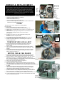
MOUNTING
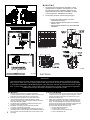
FIGURE 3
1.
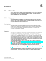
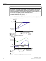
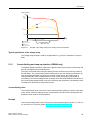
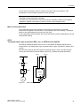
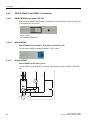
The heater must be permanently mounted in a level, upright position for operation. See Figures 3, 4, and 5 for maximum tilt angles, installation clearances, and physical dimensions. For ease of installation, a variety
of mounting kits are available from the factory.
2. The mounting structure must be strong enough to:
a.support the heater’s weight, refer to the “Specifications” section,
b.provide sufficient stiffness to prevent excessive vibration, and
c.withstand harsh situations such as transportable installations.
3 3/4”
7.75
7.75
7.75
198
198
198
FIGURE 5
FIGURE 4
ELECTRICAL
WARNING
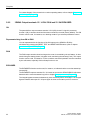
Disconnect heater from power supply at integral disconnect or fuse box before opening enclosures or servicing
heater. Lock the switch in the "OFF" (open) position and/or tag the switch to prevent unexpected power application.
IF INTEGRAL DISCONNECT IS BEING SERVICED, verify that power has been disconnected at fuse box or main
panel. Lock the switch in the "OFF" (open) position and/or tag the switch to prevent unexpected power application.
Installation and wiring of the heater must adhere to all application codes.
GENERAL
FIELD WIRING
1.
2.
3.
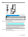
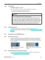
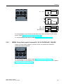
1. The supply conductors, ground conductor, and room thermostat
conductors (see point 2, page 5) all pass through the 1” NPT
opening (see Figure 6) and are to be wired into the control
enclosure (see Figure 7A).
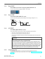
2. Heater may be supplied with a factory installed built-in room
thermostat (see Figure 8). On heaters not supplied with this
option, it is recommended that a remote room thermostat be used. Connect the remote room thermostat conductors to the printed circuit board terminal block marked “TSTAT”.
Any thermostat used with this heater must:
a. be of an explosion-proof type,
b. be rated 125 V minimum,
c. have a minimum 2 amp capacity, and
d. open on temperature rise.
Use only copper conductors and approved explosion-
proof wiring methods during installation. Refer to the “Technical Data” table and heater data plate for conductor rating.
External overcurrent protection is required. Refer to the “Technical Data” table and heater data plate for voltage, frequency amperage, and phase. Supply voltage is to be within 10% of the data plate voltage.
The heater must be installed by qualified personnel in strict
compliance with electrical codes.
4. All heaters come factory prewired and ready for direct
connection to the power supply leads.
5. The heater must be individually fused, preferably with Class J
time-delay fuses for maximum safety. Unless stated otherwise in
your local code, fuse size shall be 125% of line current or next
6 size larger.
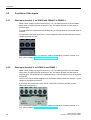
3. Heater may be supplied with a factory installed built-in integral
disconnect. (See Figure 7B)
Field Wiring for Integral Disconnect:
a. Power Supply conductors and Ground conductor pass through
1"NPT opening of Disconnect Enclosure (see Figure 7B).
Supply conductors to be wired to Disconnect Switch inside.
Ground conductor to be wired to Ground Lug fastened to inside
of Disconnect Enclosure.
b. If applicable, Remote Room Thermostat conductors pass
through 3/4"NPT opening (see Figure 7b) and are to be wired to
printed circuit board terminals marked “T’STAT”.
c. To reduce risk of ignition of hazardous atmospheres, conduit
runs must have a sealing fitting connected within 18 inches
(457 mm).
Factory installed conduits require no further sealing. Integral
Disconnect is sealed at factory.
4. The internal grounding terminal in the control enclosure (or in the integral disconnect enclosure when this option is provided) shall
be used as the equipment grounding means. An external bonding
terminal is provided for a supplementary bonding connection where
local authorities permit or require such a connection.
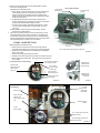
1“ NPT opening
for field wiring
Air
intake
Motor
junction box
Control enclosure
and cover
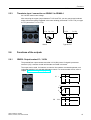
1. Before application of electrical power:
a. Check that all connections are secured and comply with the
applicable wiring diagram (see Figure 9) and code requirements,
b. Confirm that the power supply is compatible with the data plate rating of the heater,
c. Remove any foreign objects from the heater,
d. Install all covers and verify that all enclosures are well secured, and
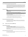
e. Ensure that the fan rotates freely. See Figure 6 for proper direction
of fan rotation.
Contactor load
side terminals, this
side for factory
wiring only.
Do not install conduit below heater (see Figure 3).
FIGURE 6
Connect supply conductors
to this side of contactor.
For a 1-phase
heater, use these
contactor lugs.
Active and spare
fuses (see parts list)
Printed circuit board’s
terminal block
FIGURE 7A
Optional Built-in Disconnect
& Field Wiring
Sealed at Factory
Switch load side
terminals, this
side for factory wiring
only.
Air exits through
louvers.
Fan
rotation
FINAL INSPECTION
Control Enclosure & Field Wiring
Rear View of Heater
Optional factory
installed built-in
room thermostat.
Optional factory
installed built-in
disconnect.
FIGURE 8
3/4" NPT
(Remote Room
Thermostat
if applicable)
Terminals marked
“T’STAT”
1" NPT
(Power Supply)
For a 1-phase heater use these
Switch terminals
Connect Supply Conductors to
this side of Switch
FIGURE 7B
7
8
FIGURE 9
(A)
14.4
24.0
36.1
48.1
8.3
13.9
20.8
27.8
41.6
12.5
20.8
31.3
41.7
62.5
7.2
12.0
18.0
24.1
36.1
48.1
6.3
10.4
15.6
20.8
31.3
41.7
3.6
6.0
9.0
12.0
18.0
24.1
30.1
36.1
42.1
2.9
4.8
7.2
9.6
14.4
19.2
24.1
28.9
33.7
(A)
18.0
30.0
45.1
60.1
10.4
17.4
26.0
34.8
52.0
15.6
26.0
39.1
52.1
78.1
9.0
15.0
22.5
30.1
45.1
60.1
7.9
13.0
19.5
26.0
39.1
52.1
4.5
7.5
11.3
15.0
22.5
30.1
37.6
45.1
52.6
3.6
6.0
9.0
12.0
18.0
24.0
30.1
36.1
42.1
(AWG)
12
10
6
4
14
12
10
8
6
12
10
8
6
2
14
14
10
8
6
4
14
14
12
10
8
6
14
14
14
14
10
8
8
6
6
14
14
14
14
12
10
8
8
8
(A)
20
30
50
70
15
20
30
35
60
20
30
40
60
80
15
15
25
35
50
70
15
15
20
30
40
60
15
15
15
15
25
35
40
50
60
15
15
15
15
20
25
35
40
45
°F
19.0
31.6
27.9
37.2
11.2
18.6
27.9
37.2
27.1
19.0
31.6
27.9
37.2
27.1
19.0
31.6
27.9
37.2
27.1
36.1
19.0
31.6
27.9
37.2
27.1
36.1
19.0
31.6
27.9
37.2
27.1
36.1
22.0
26.4
30.7
19.0
31.6
27.9
18.1
27.1
36.1
45.2
26.4
30.7
°C
10.5
17.6
15.5
20.7
6.2
10.3
15.5
20.7
15.1
10.5
17.6
15.5
20.7
15.1
10.5
17.6
15.5
20.7
15.1
20.1
10.5
17.6
15.5
20.7
15.1
20.1
10.5
17.6
15.5
20.7
15.1
20.1
12.2
14.6
17.1
10.5
17.6
15.5
20.7
15.1
20.1
25.1
14.6
17.1
Contactor
Part
Number
Maximum
Fuse Size
(W)
2700
4700
7200
9690
2700
4700
7200
9700
14400
2700
4700
7200
9700
14400
2700
4700
7200
9700
14400
19400
2700
4700
7200
9700
14400
19400
2700
4700
7200
9700
14400
19400
24200
29200
34200
2700
4700
7200
9700
14400
19400
24200
29200
34200
Temperature
Rise
C
Core Kit
Part Number
Supply
Wire
2.7
2.7
2.7
2.7
1.4
1.4
1.4
1.4
1.4
2.7
2.7
2.7
2.7
1.4
1.4
1.4
1.4
1.4
1.4
1.4
1.3
1.3
1.3
1.3
1.3
1.3
0.7
0.7
0.7
0.7
0.7
0.7
1.0
1.0
1.0
0.6
0.6
0.6
0.6
0.6
0.6
0.8
0.8
0.8
Minimum
Circuit
Ampacity
1
1
1
1
3
3
3
3
3
1
1
1
1
1
3
3
3
3
3
3
1
1
1
1
1
1
3
3
3
3
3
3
3
3
3
3
3
3
3
3
3
3
3
3
Total
Current
(kW)
3.0
5.0
7.5
10.0
3.0
5.0
7.5
10.0
15
3.0
5.0
7.5
10.0
15.0
3.0
5.0
7.5
10.0
15.0
20.0
3.0
5.0
7.5
10.0
15.0
20.0
3.0
5.0
7.5
10.0
15.0
20.0
25.0
30.0
35.0
3.0
5.0
7.5
10.0
15.0
20.0
25.0
30.0
35.0
Heater
Wattage
*
°
°
°
°
°
°
(V)
208
208
208
208
208
208
208
208
208
240
240
240
240
240
240
240
240
240
240
240
480
480
480
480
480
480
480
480
480
480
480
480
480
480
480
600
600
600
600
600
600
600
600
600
Max. Motor
Nameplate
Current
*
Phase
*
Nominal
Wattage
FX5-208160-030
FX5-208160-050
FX5-208160-075
FX5-208160-100
FX5-208360-030
FX5-208360-050
FX5-208360-075
FX5-208360-100
FX5-208360-150
FX5-240160-030
FX5-240160-050
FX5-240160-075
FX5-240160-100
FX5-240160-150
FX5-240360-030
FX5-240360-050
FX5-240360-075
FX5-240360-100
FX5-240360-150
FX5-240360-200
FX5-480160-030
FX5-480160-050
FX5-480160-075
FX5-480160-100
FX5-480160-150
FX5-480160-200
FX5-480360-030
FX5-480360-050
FX5-480360-075
FX5-480360-100
FX5-480360-150
FX5-480360-200
FX5-480360-250
FX5-480360-300
FX5-480360-350
FX5-600360-030
FX5-600360-050
FX5-600360-075
FX5-600360-100
FX5-600360-150
FX5-600360-200
FX5-600360-250
FX5-600360-300
FX5-600360-350
Voltage
Model
Note
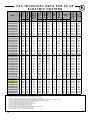
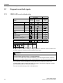
F X 5 T E C H N I C A L D ATA F O R 6 0 H Z
E L E C T R I C H E AT E R S
12116
12117
12118
12119
12116
12117
12118
12119
12120
12122
12123
12124
12125
12126
12122
12123
12124
12125
12126
12127
12129
12130
12131
12132
12133
12134
12129
12130
12131
12134
12133
12134
12135
12136
12137
12138
12139
12140
12141
12142
12143
12144
12145
12126
10557
10557
10557
10558
10557
10557
10557
10557
10557
10557
10557
10557
10557
10558
10557
10557
10557
10557
10557
10558
10557
10557
10557
10557
10557
10557
10557
10557
10557
10557
10557
10557
10557
10557
10557
10557
10557
10557
10557
10557
10557
10557
10557
10557
NOTES:
* Exceeds the 48 Amp Curcuit limit of NEC 424-22. DS5 not available for these units.
° 480 - 1 phase units are certified Class I, Div. 1, Group D and Class II, Div. 1 Groups F & G.
1. Minimum conductor size for 86˚F (30˚C) ambient. Derate conductor for ambient temperature. Use minimum 194˚F (90˚C) insulation.
2. Heater is functioning normally if at rated voltage the amp draw is within 10% of the value in this table.
3. Operation at lower voltages will result in reduced heat output and amp draw
4. Add "T" to model number when adding a built-in thermostat
5. Add "D" to model number when adding a built-in disconnect switch
6. Add "P" to model number when adding a built-in pilot light
7. Add "S" to model number when adding a 3-way switch
8. Add "H" to model number for units with high "off" (deenergized) ambient temperatures
9. Add "U" to model number for units with continuous fan option.
10. Add "A" to model number for units with stainless steel cabinet.
10
US
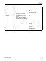
SPECIFICATIONS FOR ALL 60 HZ MODEL
Nominal kW
Max. Altitude (ft.)
(m)
@ 70°F (CFM) @ 21°C (m3/hr.)
Air Flow
3
12,000
3,658
5
7.5
8,000
2,438
10,000
3,048
500
10
7,000
2,134
15
20 10,000
3,048
7,000
2,134
25
30
10,000 7,000
3,048 2,134
850
1750
3600
850
1444
2973
6116
Horizontal Air Throw (ft.)
(m)
15
4.6
30
9.1
40
12.2
70
21.3
Max. Mounting Height (ft.)
(to underside)
(m)
7
2.1
10
3.0
10
3.0
20
6.1
Motor Power
(HP)
1/2
1/2
1/2
(min)
(kW)
0.373
0.373
0.373
Fan Diameter (in.)
(mm)
12
305
16
406
20
508
Net
Weight
without
DS5
(lbs.)
(kg)
140
63.5
168
76.2
201
91.2
with DS5
(lbs.)
(kg)
152
78.9
180
81.6
213
96.6
without
DS5
(lbs.)
(kg)
194
88
218
98.9
252
114.3
with
DS5
(lbs.)
(kg)
206
93.4
230
104.3
264
119.7
Shipping
Weight
35
6,000
1,829
Hazardous Location Rating
Class I, Groups C and D; Class II, Groups E, F and G;
Temperature Code T3B [329°F (165°C)]
Enclosures NEMA Type 7 & 9. For dry, indoor use only. Do not immerse in water. Do not store or use in areas exposed to rain or snow
Motor Type
Explosion-proof. Thermally protected. Permanently lubricated ball bearings. 1725 RPM
Fan
Aluminum blade. Steel spider and hub with 5/8 in. (15.875 mm) bore
Fan Guard
Split design with close wire spacing. 1/4 in. (6.3 mm) dia. probe will not enter
Mounting Holes
Four 9/16 in. (14.3 mm) diameter holes at top of heater
Heating Elements
Three long-life, low watt-density, high grade metal-sheathed elements
Temperature High-Limit
Automatic reset type, snap-action bimetal, open on temperature rise. Rated 100,000 cycles
at 10 amps, handles 0.128 amps
Control Circuit
120 Volts, 0.128 amps, 15VA. (Grounded)
Optional Built-in Thermostat
Explosion-proof. 36°F to 82°F (2°C to 28°C)
Optional Built-in Disconnect Switch
Optional Three Way Switch
DS5 for use only on heaters with total current not exceeding 48-Amps.
Lockout handle accepts 1/4” diameter padlock shackle
Fan only, Off, Auto
Optional Pilot Light
Indicates heat-on cycle
Control Transformer
Multi-tap primary, 120 V secondary, 50 VA
Contactor
60 or 80 amp. Rated for 1,000,000 mechanical operations. 120 Volts, 15VA coil
(separately fuse-protected)
Heat Transfer Fluid
Long life formulated propylene glycol and water
Cabinet Material
14 ga. (0.075 in.) (1.90 mm) steel. Epoxy coated with five-stage pretreatment, including iron
phosphate. Optional stainless steel
Core
Steel with integral aluminum fins, vacuum charged and hermetically sealed
Conduit Material
Heavy walled, 0.122 in. (3.1 mm) steel
Overpressure Protection
Preset 100 psig (690 kPa) pressure relief valve, aluminum body, no field serviceable parts
Operational Temperature Limitations
-4°F to 104°F (-20°C to 40°C)
Storage Limitations
-49°F to 176°F (-45°C to 80°C), short term to 248°F (120°C). Do not immerse in water Donot expose to rain or snow
12
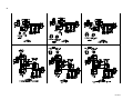
H E AT E R A S S E M B LY D I A G R A M
5
22
23
4
6
7
Optional Built-in
thermostat replaces
item #16
1
3
8
18
See
control enclosure
assembly diagram
(below)
9
10
11
9
2
19
20
See high-limit
assembly diagram
(below)
12
21
17
13
16
41
14
Optional
built-in
disconnect
switch kit
15
HIGH LIMIT
CONTROL ENCLOSURE
ASSEMBLY DIAGRAM
ASSEMBLY DIAGRAM
36
24
33
35
32
25
29
37
34
30
26
27
28
31
BUS-BAR CONFIGURATION
FOR ALL 3-PHASE
(EXCEPT 380 50 HERTZ & 400 50 HERTZ)
BUS-BAR CONFIGURATION
ALL 1-PHASE MODELS
38
38
39
40
BUS-BAR CONFIGURATION
FOR ALL 3-PHASE 380 V & 400 V 50 HERTZ MODELS
39
39
40
13
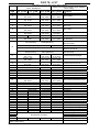
PA R T S L I S T
F O R C E D A I R E L E C T R I C H E AT E R S
Please have model and serial number available
before calling
PART NUMBERS
ITEM
1
2
3
4
5
6
7
8
9
2.5 - 4.6 kW
6.3 - 10 kW
**
**
Painted: 9203
S.S.: 9507
Painted: 9191
S.S.: 9192
4075
Painted: 9200
S.S.: 9513
Painted: 9197
S.S.: 9510
Painted: 3782
S.S.: 9212
4022
4023
Painted: 4078
S.S.: 9504
1979 (Emerson)
10
11
12
13
14
15
16
17
18
19
20
21
12.5 - 20 kW
**
Painted: 9204
S.S.: 9508
Painted: 9193
S.S.: 9194
4076
Painted: 9201
S.S.: 9514
Painted: 9198
S.S.: 9511
Painted: 3783
S.S.: 9213
4024
Painted: 4079
S.S.: 9505
20.9 - 35 kW
**
Painted: 9205
S.S.: 9509
Painted: 9195
S.S.: 9196
4077
Painted: 9202
S.S.: 9515
Painted: 9199
S.S.: 9512
Painted: 3784
S.S.:9214
4025
Painted: 4080
S.S.: 9506
10388 (Marathon)
9896 (Baldor)
N/A
1699 (Emerson)
10387 (Marathon)
2433 (Emerson)
10672 (Marathon)
Painted: 3789
Painted: 3789 Painted: 3789
S.S.: 9112
S.S.: 9112
S.S.: 9112
Painted: 3785
Painted: 3786 Painted: 3787
S.S.: 9206
S.S.: 9207
S.S.: 9208
Painted: 3788
Painted: 3788 Painted: 3788
S.S.: 9111
S.S.: 9111
S.S.: 9111
3737 (Emerson Motors) 4590 ( Baldor & Marathon Motors)
9500
3813
10389
5371
5371
5371
3813
3813
3813
9314
9315
9316
9679
9679
9679
3510
3510
3510
Painted: 9354
Painted: 9355 Painted: 9356
S.S.: 9516
S.S.: 9517
S.S.: 9518
4983
4983
4983
5032
5032
5032
**
**
**
10556 (60HZ)
11295 (50HZ)
3809
3809
3809
3809
1876
1876
1876
1876
9357
9357
9357
9357
3514
3514
3514
3514
9158
9158
9158
9158
9279
9279
9279
9279
9775
9775
9775
9775
9267
9267
9267
9267
9289
9289
9289
9289
-
22
23
24
25
26
27
28
29
30
31
32
33
34
35
36
37
38
39
Provided with Core Kits**
40
41
**See technical data table for part numbers. NOTE: For items not shown,
please contact factory.
14
Description
Core
Panel, Bottom
Panel, Left Side
Louver Kit, c/w screws
Panel, Top
Panel, Right
Panel, Fan Shroud
Fan Blade
Fan Guard Kit
208/240V 1PH 60HZ
220V 1PH 50HZ
480V 1PH 60HZ
208/240/480V 3PH 60HZ
380/415V 3PH 50HZ
600V 3PH 60HZ
Bracket, Motor Mount Right
Channel, Motor Mount
Bracket, Motor Mount Left
Coupling, Motor
Conduit, Motor
Cover, Thermostat Enclosure
Conduit, Control Enclosure
Conduit, Element Enclosure
Enclosure, Element
Cover, Element Enclosure
Panel, Element Enclosure Guard
Enclosure, Thermostat
Thermostat, Built-in-kit
Enclosure, Control
Contactor
Transformer
Bracket, Printed Circuit Board
Terminal, 6-14 Ga. Screw Lug
Fuse, Buss MDQ - 1/2 Amp
Assembly, Printed Circuit Board
Cover, Control Enclosure
Bulb, Pilot Light
Switch, Explosion Proof 3-Way
Thermowell, Ambient High-Limit
High Limit, Ambient Temperature
Plug, 1" NPT Explosion Proof
Temperature High-Limit Kit
Bus-Bar, Straight
Bus-Bar, Small Curved
Bus-Bar, Large Curved
Kit, DS5 Assembly
REPAIR & REPLACEMENT
WARNING
Disconnect heater from power supply at integral disconnect or fuse box before
opening enclosures or servicing heater. Lock the switch in the “OFF” (open)
position and/or tag the switch to prevent unexpected power application.
IF INTEGRAL DISCONNECT IS BEING SERVICED, verify that power has
been disconnected at fuse box or main panel. Lock the switch in the “OFF”
(open) position and/or tag the switch to prevent unexpected power application.
Heater surfaces may be hot.
1.
After repairing any component:
a. check that electrical connections are correct and secure (see Figure 9),
b. remove any foreign material from enclosures,
c. install and secure all covers,
d. ensure that all fasteners are tight,
e. remove all foreign objects from heater, and
f. ensure air exits through louvers and fan rotates counterclockwise when
viewed from rear of heater (see Figure 14).
Loosen
bolts
only,
do not
remove.
{
}
Conduit
Junction
Enclosure
Remove this
core mounting
bolt & two
others on the
opposite side.
Loosen
bolts
only,
do not
remove.
Control
Enclosure
Element
Enclosure
FIGURE 10
CORE
The heater core is vacuum charged and not field repairable.
For core removal:
1. Remove cabinet bottom and element enclosure cover.
2. Disconnect all wires entering element enclosure (see Figure 10).
3. Slightly loosen all cabinet bolts shown in Figure 10, to prevent the core
frombinding.
4. With an assistant supporting the weight of the core, remove the 3 core
mounting bolts. Carefully lower the core out of the cabinet
(see Figure 11).
5. To return core to factory, use crate supplied with exchange core
to protect
the element terminals and plate threads.
6. To reinstall, lift the core up into cabinet while an assistant guides the
element wires into the element enclosure conduit.
7. Position the core and tighten the 3 core mounting bolts. Tighten the
remaining cabinet bolts.
FIGURE 11
Thermowell
3/32”
(2mm)
Drop
T E M P E R AT U R E H I G H - L I M I T
1.
2.
3.
Remove temperature high-limit assembly and clean the inside of the
thermowell (see Figure 12). A clean thermowell will ensure good
thermal contact.
Use only a factory supplied temperature high-limit to ensure safe operation.
(refer to the instructions that accompany the replacement Temperature HighLimit Kit).
Reinstall the temperature high-limit assembly with the snap ring and spring
into the thermowell without damaging the insulating tube. Secure in place
with the cotter pin (see Figure 13).
1.
2.
3.
4.
5.
6.
7.
8.
9.
10.
Remove bolts holding the motor to the motor mount. On units with a built
in thermostat, remove the bolts on the back of the thermostat enclosure.
Remove conduit #1 located between motor junction box and control
enclosure by turning it in the direction illustrated (see Figure 14).
Note conduits #1 and #2 are not interchangeable and have left hand threads on
one end, this end is indicated by a machined groove.
Remove the 2 piece fan guard assembly (see Figure 15).
Lift the motor assembly off the motor mount.
Before removing the fan, measure and record the location of the fan hub on the
motor shaft (see Figure 16). If difficult to remove, use a gear puller on the fan hub.
To reassemble, place motor assembly onto motor mount and fasten the fan guard Air inlet
to cabinet.
Simultaneously engage and tighten both ends of conduit #1 into enclosures.
Leave a 1/16” to 3/16” (1.6 to 4.8 mm) gap between the motor and fan guard
(see Figure 16). Adjust conduit #2 to center the fan in the shroud.
To ensure a minimum 5 thread engagement, threaded ends of conduits must
protrude a minimum of 1/16” (1.6mm) into enclosures. The groove on conduit #2
must not be more than 7/8” (22mm) from motor coupling (see Figure 14).
Bolt motor to motor mount. Manually spin the fan blade to ensure fan rotates freely.
Air must exit through louvers and fan must rotate counterclockwise when viewed
from rear of heater (see Figure 14).
FIGURE 12
M O TO R , FA N & FA N G U ARD
7/8” (22mm)
(From groove to
face of coupling)
FIGURE 13
Rotation
Remove
Install
Install
Remove
Conduit #2
Conduit #1
FIGURE 14
15
PRINTED CIRCUIT BOARD
1.
2.
After removing the printed circuit board (P.C. Board) bracket assembly
from the control enclosure, separate the P.C. Board from the bracket
by cutting off the plastic spacers (see Figure 18).
Reinstall a new factory supplied P.C. Board onto the mounting bracket
using new non-conducting spacers of the same length. Spacers are
supplied with a new P.C. Board. Reinstall the control circuit ground
wire to the printed circuit board bracket (see Figure 9).
C O N TA C T O R
1.
2.
Loosen, but do not remove contactor mounting screws. Slide
contactor off mounting screws.
Replace with a factory supplied contactor of the same rating.
TRANSFORMER
FIGURE 15
1.
2.
Replace with a factory supplied transformer of the same rating.
On the new transformer, select primary wires to match heater voltage.
Ensure that the correct transformer secondary lead is grounded (see
Figure 9). Individually terminate all unused wires using closed
end connectors.
FUSE
Replace fuse with one of the same type and rating as indicated on P.C.
Board or refer to parts list. An extra fuse should be stored in the clips
marked “SPARE”.
H E AT I N G E L E M E N T S
Heating elements are an integral part of the vacuum charged core. A factory
exchange core can be shipped immediately from stock. Refer to “Core”
section for details.
C A B I N E T PA N E L S
Bolt-on cabinet panels are individually replaceable.
FIGURE 16
1/16” to 3/16”
(1.6 to 4.8mm)
FIGURE 17
FIGURE 18
16
5918 Roper Road, Edmonton, Alberta, Canada T6B 3E1
Phone: (780) 466-3178
Fax: (780) 468-5904
PLEASE ADHERE TO INSTRUCTIONS PUBLISHED IN THIS MANUAL.
Failure to do so may be dangerous and may void certain provisions of your warranty.
For further assistance, please call:
24 Hr. Hotline: 1-800-661-8529
(U.S.A. and Canada)
Please have model and serial numbers available before calling.
WARRANTY: Under normal use the Company
warrants to the purchaser that defects in material or
workmanship will be repaired or replaced
without charge for a period of 36 months from date of
shipment. Any claim for warranty must be reported to
authorized repair or replacement within the terms of
this warranty.
Subject to State or Provincial law to the contrary, the
Company will not be responsible for any expense for
installation, removal from service, transportation, or
damages of any type whatsoever, including damages
arising from lack of use, business interruptions, or
incidental or consequential damages.
The Company cannot anticipate or control the
conditions of product usage and therefore
accepts no responsibility for the safe application and
suitability of its products when used alone or in
combination with other products. Tests for the safe
application and suitability of the products are the sole
responsibility of the user.
This warranty will be void if, in the judgment of the
Company, the damage, failure or defect is the result of:
• vibration, radiation, erosion, corrosion, process
contamination, abnormal process conditions,
temperature and pressures, unusual surges or
pulsation, fouling, ordinary wear and tear, lack of
maintenance, incorrectly applied utilities such as
voltage, air, gas, water, and others or any
combination of the aforementioned causes not
•
any act or omission by the Purchaser, its agents,
servants or independent contractors which for
greater certainty, but not so as to limit the generality
of the foregoing, includes physical, chemical or
mechanical
abuse,
accident,
improper
installation of the product, improper storage and
handling of the product, improper application or the
misalignment of parts.
Edmonton
1-800-661-8529
(780) 466-3178
F 780-468-5904
Oakville
1-800-410-3131
(905) 829-4422
F 905-829-4430
Orillia
1-877-325-3473
(705) 325-3473
F 705-325-2106
manufacturing defects apparent within 30 days from
the date of installation.
The
Company
neither
assumes
nor
authorizes any person to assume for it any other
obligation or liability in connection with the product(s).
The Purchaser agrees that all warranty work required
after the initial commissioning of the product will be
provided only if the Company has been paid by the
Purchaser in full accordance with the terms and
conditions of the contract.
The Purchaser agrees that the Company makes
no warranty or guarantee, express, implied or
statutory, (INCLUDING ANY WARRANTY OF
MERCHANTABILITY OR WARRANTY OF FITNESS
FOR A PARTICULAR PURPOSE) written or oral, of
the Article or incidental labour, except as is expressed
or contained in the agreement herein.
LIABILITY: Technical data contained in the catalog or
on the website is subject to change without notice. The
Company reserves the right to make dimensional and
other design changes as required. The Purchaser
acknowledges the Company shall not be obligated
to modify those articles manufactured before the
formulation of the changes in design or improvements
of the products by the Company.
The Company shall not be liable to compensate or
indemnify the Purchaser, end user or any other party
against any actions, claims, liabilities, injury, loss, loss
of use, loss of business, damages, indirect or consees (including legal expenses), costs, obligations and
causes of action of any kind arising wholly or partly
from negligence or omission of the user or the misuse, incorrect application, unsafe application, incorrect storage and handling, incorrect installation, lack
of maintenance, improper maintenance or improper
operation of products furnished by the Company.
Greensburg
1-800-473-2402
(812) 663-4141
F 812-663-4202
Houston
1-855-219-2101
(281) 506-2310
F 281-506-2316
Denver
1-855-244-3128
(303) 979-7339
F 303-979-7350
Powerware series
Agnico Eagle, Baker Lake
Jet-A Tank Farm
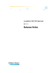
Control equipment UPS
350-1500 VA power protection for PC,
telephone and networking equipment
Eaton 5110 UPS
Features
• Protect the integrity of your data and applications by shielding
electronic equipment from power outages, surges, sags, brownouts, and overvoltage conditions
• Save space with a compact design that can be deployed as a
tower or under a computer monitor
• Protect loads on eight outlets—four with surge suppression and
battery backup, four with surge suppression only
• Deliver consistent, clean output with automatic voltage regulation
(AVR) that doesn’t drain battery power
• Extend UPS service life with user-replaceable batteries
• Protect networked equipment from “back door” power surges
coming through LAN or telephone lines
• Stay informed of power problems and battery conditions with
audible alarms and remote alarm notification via e-mail, pager,
the Web, or SNMP
• Deliver short-term mobile power with start-on-battery capability
• USB port and cables are standard
Product Snapshot
• Rest easy with a three-year limited warranty with product
registration and a $150,000 load protection guarantee (US and
Canada); optional multi-year Gold Plan service is available to
provide repair and replacement coverage that goes beyond the
provisions of the limited warranty
Product rating: 350–1500 VA
Voltage 120V and 230V
Frequency:
50 Hz and 60 Hz, auto-sensing
Configuration:Plug-and-play tower or under monitor
Topology:Line-interactive
As much as business depends
on electric power, public utility
power is anything but dependable. By law, public utilities do
not have to supply computergrade power. That’s bad news
in an age when sensitive computer systems form the core of
virtually all business functions.
Advances in processing capacity
and miniaturization make these
systems more susceptible than
ever to power fluctuations—and
make system crashes and data
losses more costly than ever.
According to National Power
Laboratories (NPL) and the
Electric Power Research Institute,
the typical power customer location
can experience an average of 24
power disturbances each month,
costing the US economy $119
billion to $188 billion every year.
You don’t have to be a part
of those statistics. Effective
protection is here, at a very
attractive price.
The Eaton® 5110 uninterruptible
power system (UPS) provides
a layer of defense between
your equipment and raw utility power. This line-interactive
UPS constantly safeguards your
systems from power outages,
surges, sags, brownouts, and
overvoltage conditions—and
provides varying degrees of protection from other power problems as well. If utility power is
interrupted, even briefly, the
5110 transfers to battery power.
Introducing the Eaton 5110 UPS
Affordable protection
for small to medium
organizations
Incorporating more than 40
years of UPS design experience,
the 5110 provides cost-effective
power management, backup
power, and power quality for
office workstations, PBX or key
telephone systems, servers,
small network nodes, point-ofsale systems, and computer
peripheral devices. This UPS is
ideal for any small- to mid-sized
business or institutional setting
where reliable power must be
provided at an affordable price.
Automatic voltage regulation (AVR)—clean power
without draining the battery
The 5110 uses AVR to smooth
out wide fluctuations in input
voltage. If input voltage varies
as much as 25 percent over
or 23 percent under nominal
voltage—which can easily happen when running on generator
power or in severe environments—the 5110 accepts this
inconsistent voltage and delivers clean, consistent output
for protected equipment. AVR
enables you to work through
even the most frequent brownouts and power sags.
UPS
battery
LED
Warning LED:
Low battery = steady
Overload = flashing
Unlike typical line-interactive
systems, the 5110 does not
switch back and forth to battery
power to accomplish this voltage regulation—which would
shorten battery life and increase
battery replacement costs.
As a result, battery power is
conserved for when you really
need it.
Eight outlets in a
low-profile tower
The 5110 occupies a small
footprint—about the size of a
dictionary for low-power units
(500–700 VA), or a sleek tower
for higher-rated models (1000–
1500 VA). This tower package
fits easily under a monitor.
UPS
power
LED
Battery
access
panel
2
EATON CORPORATION
Eaton 5110 UPS
Incoming power lines aren’t
the only source of damaging
surges. Power also travels
across network links, such as
LANs and telephone lines. The
5110 uses an integral network
transient protector to safeguard
network-connected equipment—such as fax machines,
modems, or electronic telephones—from “back door”
power surges coming through
network or phone wiring.
Short-term power for
mobile applications
The cost-effective design features eight outlets, four with
surge protection and battery
backup and four with surge
protection only. You can plug
less critical equipment, such as
printers or monitors, into surgeprotection-only outlets that do
not drain battery power.
On/Off/Test
switch
Protection for data lines
The 5110 supports start-onbattery capability, which means
you can unplug the UPS from
utility power, then restart and
run it from battery power elsewhere. This capability offers
tremendous flexibility for shortterm powering needs, such
as in mobile offices or service
vans.
UPS
communication
port
Surge-protected
outlets (four each)
with spacing for
transformer block
plug-in
Input
line cord
User-replaceable batteries
for extended service life
Many UPS products in this
range are useful only up to the
service life of their batteries.
When the battery fails, the unit
is worthless. Not so with the
5110. You can replace the batteries yourself—a simple process that can be performed by
easy access through the front
panel. When the audible alarm
indicates that batteries need
replacing, you can safely and
easily install supplied batteries
and remove the old batteries for
proper disposal and recycling.
You can also choose to return
the entire unit for repair or battery replacement under our warranty and service programs.
Easy-to-understand LEDs
and audible alarms
You never have to guess about
the status and condition of
your 5110. Simple LED indicators and audible alarms warn of
power problems and low battery
conditions. The Battery LED
illuminates when the UPS is
operating on battery power. The
Warning LED turns on when the
battery is low and flashes under
overload conditions.
Data line
protection
UPS-backed
(four outlets)
with spacing
for transformer
block plug-in
Circuit
breaker
The 5110 delivers confidence—confidence that
your vital business equipment is protected and
confidence that Eaton will be there with you for
the long term.
Remote UPS monitoring
from anywhere
Warranty coverage with
load protection guarantee
You don’t have to be within sight
of the UPS to stay informed.
You can connect the 5110 to a
network using the built-in USB
port, and monitor its working
status. The UPS comes with
Eaton LanSafe® software, free
of charge. This UPS management software gives you control
and visibility over all your UPSs,
using an intuitive, graphical
interface.
Rest easy with industry-leading
protection from Eaton. The 5110
is backed by a two-year limited
warranty and a $150,000 load
protection guarantee. We’re that
confident of the performance
and reliability of the 5110.
To find out more about how the
5110 can protect your critical
equipment, applications, and
data:
www.eaton.com/powerquality
800-356-5794
5110 technical specifications1
Operation
Input voltage range
0–160Vac/0–300Vac
Output voltage range
Nominal -23% to +25%
On battery output voltage
Nominal -12% to +10%
Frequency
50/60 Hz auto sensing
Lighting / surge protection
120V models 320 joules; 230V models 476 joules
Safety UL 1778, designed to meet UL497A, CAN/CSAOC22.2 No107.1/IEC 62040-1-1: CE low voltage directive
EMI
FCC Class B/IEC 62040-2, EN55022: Class B: CE EMC directive
Transfer time to battery/AC
2-6 msec. typical
Battery type
Sealed, maintenance free lead-acid battery
Typical backup time
Three minutes at full rated load
Internet / phone / fax protection RJ11/RJ45
Short circuit protection
Circuit breaker
Communication port
USB
Environmental
Operation temperature
Operation relative humidity
Storage temperature
0°C ~ 40°C
0 to 95% non-condensing
-15°C ~ 50°C
Software
LanSafe software is included free of charge
Service Plans
Product
length of serviceGold Plan Part Number
5110 500-1500 VA
5110 500-1500 VA
Three years Five years
3XXGX5100XALLCX
5XXGX5100XALLCX
Replacement Batteries
Model Number
Part Number
PW5110 500 VA PW5110 700 VA PW 5110 1000 VA
PW5110 1500 VA
106711159-001
106711160-001
106711161-001
106711162-001
description
BATT. KIT 500 VA PW5110
BATT. KIT 700 VA PW5110
BATT. KIT 1000 VA PW5110
BATT. KIT 1500 VA PW5110
1. Specifications are subject to change without notice due to continuing product improvement programs.
www.eaton.com/powerquality 1.800.356.5794
3
5110 NORTH AMERICAN MODELS: 120V, 50/60 Hz
Part Power Out Model
Number
(VA/Watt)
PW5110 500
103004256-5591
500/300
Input Connection
Output Receptacles
(8) 5-15R Outlets*
Dimensions (H x W x D, inches)
10.6 x 3.4 x 10.2
Weight
(lb)
12.1
PW5110 700
103004257-5591
700/420
1.8m line cord
with 90 deg. 5-15P
(8) 5-15R Outlets*
10.6 x 3.4 x 10.2 15.2
PW5110 1000
103004258-5591
1000/600
1.8m line cord
with 90 deg. 5-15P
(8) 5-15R Outlets*
10.6 x 3.4 x 15.1
28.0
PW5110 1500
103004259-5591
1440/900
1.8m line cord
with 90 deg. 5-15P
(8) 5-15R Outlets*
10.6 x 3.4 x 15.1 29.1
Dimensions H x W x D (inches)
Weight
(lb)
10.6 x 3.4 x 10.2
13.4
1.8m line cord
with 90 deg. 5-15P
5110 INTERNATIONAL MODELS: 230V, 50/60 HZ
Part Power Out Model
Number
(VA/Watt)
PW5110 500i
103004261-5591
500/300
PW5110 700i
103004262-5591
700/420
Input Connection
Output Receptacles
IEC C14 inlet, 1.8 meter
line patch cord IEC to IEC
(8) IE C13 Outlets*
IEC C14 inlet, 1.8 meter
line patch cord IEC to IEC
(8) IE C13 Outlets*
10.6 x 3.4 x 10.2
16.5
PW5110 1000i
103004263-5591
1000/600
IEC C14 inlet, 1.8 meter
line patch cord IEC to IEC
(8) IE C13 Outlets*
10.6 x 3.4 x 15.1
29.1
PW5110 1500i
103004264-5591
1500/900
IEC C14 inlet, 1.8 meter
line patch cord IEC to IEC
(8) IE C13 Outlets*
10.6 x 3.4 x 15.1
30.2
* Four battery backup & surge protection; four surge protection only.
5110 BATTERY BACKUP TIMES (in minutes)
Load (VA)
500
700
Load (VA)
1000
1500
30W
52
63
120W
52
62
60W
35
46
180W
35
43
90W
22
34
240W
23
29
120W
14
23
300W
17
20
150W
11
16
360W
13
16
180W
8
12
420W
10
14
210W
6
10
480W
9
12
240W
5
8
540W
7
11
270W
4
7
600W
5
9
300W
3
6
660W
-
8
330W
-
5
720W
-
7
360W
-
4
780W
-
6
390W
-
4
840W
-
5
420W
3
900W
4.4
Note: Battery runtimes are approximate and may vary with equipment, configuration, battery age, temperature, etc.
UNITED STATES
8609 Six Forks Road
Raleigh, NC 27615 U.S.A.
Toll Free: 1.800.356.5794
www.eaton.com/powerquality
Canada
Ontario: 416.798.0112
Toll free: 1.800.461.9166
LATIN AMERICA
Brazil: 55.11.3616.8500
Caribbean: 1.949.452.9610
México & Central America:
52.55.9000.5252
South Cone: 54.11.4343.6323
EUROPE/MIDDLE EAST/AFRICA
Denmark: 45.3686.7910
Finland: 358.94.52.661
France: 33.1.6012.7400
Germany: 49.0.7841.604.0
Italy: 39.02.66.04.05.40
Norway: 47.23.03.65.50
Sweden: 46.8.598.940.00
United Kingdom: 44.1753.608.700
Asia Pacific
Australia: 61.2.9693.9366
New Zealand: 64.0.3.343.3314
China: 86.21.6361.5599
HK/Korea/Taiwan: 852.2745.6682
India: 91.11.4223.2300
Singapore/SEA: 65.6825.1668
Eaton, Powerware and LanSafe are
trade names, trademarks and/or service
marks of Eaton Corporation or its
subsidiaries and affiliates.
All other trademarks are property of
their respective owners.
©2009 Eaton Corporation
All Rights Reserved
Printed in USA
5110FXA
September 2009
Powerware 5110 UPS
USER'S MANUAL
The Powerware 5110 uninterruptible power system (UPS) protects your
sensitive electronic equipment from power problems such as power failures,
power sags, power surges, brownouts, and line noise.
Features:
Processor-controlled voltage regulation
Eight outlets
-Four with surge and backup protection
-Four with surge protection only
Data Line (Internet fax - modem - DSL) or telephone line surge protection jacks
Cold start capability
USB communication port
User-replaceable batteries
SAFETY INSTRUCTIONS
Once you have received the Powerware 5110 UPS product, you should remove
and inspect the product for shipping damage. If any damage is found, please
notify the carrier and your dealer. Please keep the shipping carton and the
packing foam in the event the product must be returned to the factory for service.
ATTENTION: Maintenance must be performed by a qualified personnel. Failure
to do so could result in an electric shock. Replace Battery with Powerware
supplied Battery ONLY! Although the unit may be unplugged from utility power,
hazardous voltage still may be present through the battery.
1. Place the Powerware 5110 UPS indoors in an area that has adequate airflow
and is free from excessive dust. Do NOT allow the UPS to be exposed to
moisture, rain, excessive heat or direct sunlight.
2. Use of the Powerware 5110 UPS product in life support applications where
failure of this equipment can reasonably be expected to cause failure of life
support equipment or to significantly affect its safety or effectiveness is NOT
recommended.
3. Always disconnect the input power cord from the wall outlet before replacing
the battery.
4. When replacing the battery, use the same number and type of battery.
5. Do NOT dispose of the battery in a fire: the battery may explode.
6. Do NOT open or mutilate the battery. Batteries contain an electrolyte that is
toxic and harmful to both the skin and eyes.
7. Proper disposal of the battery is required. Please refer to your local
laws/regulations regarding battery disposal.
8. Use tools with insulated handles to replace the battery to avoid personal
injury. Due to energy hazards, please remove wristwatches and jewelry such
as rings when replacing battery.
BATTERY CONNECTION REQUIRED BEFORE USE!
Connecting the Battery:
4.5 AH, 5 AH batteries (350 VA, 500 VA models)
2
7AH x 2, 9AH x 2 batteries (1000VA, 1500VA models)
1
2
Push at the top Edge to remove the
battery cover
Slide down to remove the battery cover
3
4
Connect the battery cable
Reinstall the battery cover
INSTALLATION AND OPERATION:
Following steps explain how to connect and operate the Powerware 5110 UPS.
1. Connect the UPS to a grounded power outlet.
Note: It is recommended that the battery should be charged for minimum 8 hours
to ensure full charge before placing the UPS in service.
2. Plug your computer, monitor or load to be protected into the “Battery Backup &
Surge Protection” outlets. (These outlets will provide emergency battery
backup power during power outages as well as protection from surges and
spikes.)
CAUTION: Do NOT plug LASER PRINTERS into the “Battery Backup” outlets.
CAUTION: Do NOT plug ACCESSORY SURGE strips into the “Battery Backup”
outlets.
3. Plug your peripheral equipment or non-critical loads (printer, scanner, fax,
speaker, etc.) into the “Surge Protection” outlets. (These outlets provide surge
and spike protection only, they will NOT provide battery backup power during a
utility power failure).
4. Connect your computer to the UPS using USB cable provided.
5. With your equipment turned off, switch on the UPS.
6. When the “On/Off” LED light is illuminated, turn on the connected equipment.
7. Install Power management software provided with the UPS
INDICATORS
7
1
8
4
6
5
6
5
10
9
2
3
1.On/Off Push Button
Push button switch that controls power to the UPS and initiates the self-test
function.
Depress the push button to turn on the UPS.
Depress the push button again to turn off the UPS.
The UPS will perform a self-test for about 5 seconds when the UPS is turned on.
2.AC mode (Green) LED
Indicates that AC utility power is present and regulated power (AVR) is
applied to the connected equipment.
Push at the top Edge to remove the
battery cover
3
Slide down to remove the battery cover
4
3.Fault / Warning (Red) LED
Indicates that a fault condition has occurred.
-Flashing Red LED indicates an overload condition or that the battery should
be replaced.
-Solid On LED indicates that the output is shorted or an internal UPS fault exits.
See the Indicator Table below for further detail.
4.Backup mode (Yellow) LED
Pull out the battery and connect the battery
wire to the battery terminal
Reinstall the battery cover
Indicates that the UPS is operating on battery and providing regulated AC power
to the backup only outlets and the connected equipment.
5.Battery Backup & Surge Protection Outlets
Four 5-15R output receptacles that provide both backup and surge protection.
7 AH battery (700 VA models)
2
6.Surge Protection Outlets
Four 5-15R output receptacles that provide surge and spike protection only.
7.Data /Phone/Fax Protection Connectors
8.USB Communication Port
Push at the top Edge to remove the
battery cover
3
Pull out the battery and connect the battery
wire to the battery terminal
Slide down to remove the battery cover
4
Reinstall the battery cover
The built-in USB port connects to your computer. The LanSafe monitoring and
shutdown software provided can automatically save your files and shut down
your computer in the event of a prolonged power outage. The software also
provides information regarding the status of your utility power line.
9.Circuit Breaker (resetable)
The button will protrude when the overload condition occurs. If the button
protrudes, disconnect some non-essential equipment and reset the circuit
breaker by pushing the button inward.
10.Power Cord
6 foot line cord
BATTERY REPLACEMENT PROCEDURE:
1.Disconnect the UPS from the power source and slide the battery door open.
See pictures 1 and 2.
2.Disconnect the battery and remove as indicated below. See pictures 3 and 4
3.Insert the replacement battery and reconnect the battery cables.
See pictures 6 and 7
NOTE: It is important that the connectors be firmly attached to new batteries.
4.Reposition the battery door and slide closed. See pictures 8 and 9.
NOTE: Properly recycle used battery.
4.5AH, 5AH batteries (350VA, 500VA models)
1
2
3
50 / 60 Hz auto sensing
Frequency
8 Outlets (4 Battery Backup & Surge Protection;
4 Surge Protection only)
Outlets
4
7
5
8
15%
Automatic Voltage Regulation (AVR)
6
9
Lighting / Surge Protection
320 Joules
Transfer time to Battery/AC
6ms typical
Battery Type
Maintenance free lead-acid battery
Battery Specification
350 VA: 12V 4.5 Ah
500 VA: 12V 5 Ah
750 VA: 12V 7 Ah
1000 VA: (2) 12V 7 Ah
1500 VA: (2) 12V 9 Ah
Typical Backup Time
3 MINUTES MINIMUM AT FULL RATED LOAD
RJ11/RJ45
LAN / Phone / Fax Protection
Short Circuit Protection
Circuit Breaker
Communication Port
7AH x 1 battery (700VA models)
1
USB
Operation Temperature
2
3
0 C~40 C
0 to 95% non-condensing
Operation Relative Humidity
Storage Temperature
-15 C~50 C
350 VA: 11.9 pounds / 5.4 kg
500 VA: 12.13 pounds / 5.5 kg
700 VA: 15.21 pounds / 6.9 kg
1000 VA: 28 pounds / 12.7kg
1500 VA: 29.1 pounds / 13.2 kg
Net Weight
4
5
6
350 / 500 / 700 VA: 10.6 x 3.4 x 10 in.
1000 / 1500 VA: 10.6 x 3.4 x 15 in.
Dimensions (HxWxD)
* Due to continuing product improvement programs, specifications are subject to change
without notice.
7
8
9
TROUBLESHOOTING
Symptom
UPS will not turn on
7AH x 2, 9AH x 2 batteries (1000VA, 1500VA models)
1
2
Possible Cause
Action to Take
The UPS is not connected
to the power source.
Circuit Breaker has
tripped.
Ensure the UPS is securely
connected to an AC outlet.
Reduce the amount of equipment
plugged into the “Battery Backup &
Surge Protection” outlets of the
UPS. Reset the circuit breaker by
pushing it back in. Switch the UPS
back on.
3
Turn off the UPS and reduce the
The “Battery Backup &
UPS is making a
continuous sound and the Surge Protection” outlets amount of equipment connected to
these outlets.
“Overload” indicator is on are overload.
4
7
5
8
6
UPS does not provide
expected runtime
9
UPS does not power
essential equipment
during an outage
Status Indicators
The UPS provides both visual and audible status indicators. Visual indicators
consist of three LEDs to represent the following conditions:
On utility power operation
On battery power operation
UPS fault/alarm
LED Indicator Table
On Utility (AC mode)
On Battery (Backup mode)
Low Battery
Fault/Output Short
Overload/Check Battery
Sounding every 5 seconds
Sounding (two beeps) every 5 seconds
Sounding every 0.5 seconds
Sounding (three beeps) every 30 seconds
Continuous sounding
Sounding (three beeps) every 5 seconds
SPECIFICATIONS
Model Numbers
PW5110 350 USB
PW5110 500 USB
PW5110 700 USB
PW5110 1000 USB
PW5110 1500 USB
Charge the battery for 8 hours. The
UPS runtime is reduced until the
battery is fully charged.
Unplug non-essential equipment
(printers, scanners, etc) from the
Battery Backup outlets and plug
into 'Surge Only' outlets
Disconnect non-essential equipment
from the UPS. Reset (push in) the
circuit breaker and switch the UPS on.
Plug equipment in one-at-a-time. If
the circuit breaker trips again,
disconnect the device that caused the
breaker to trip.
The battery has reached Replace the battery or the battery
module.
the end of its life.
Equipment plugged into a Unplug device from 'Surge Only' outlet
Surge Only outlet.
and move to a 'Battery Backup outlet.
Internal UPS fault.
Contact Technical Support (see
Service and Support below).
SERVICE AND SUPPORT
Green Lighting
Yellow Lighting
Yellow Flashing
Red Lighting
Red Flashing
LED Audible Alarm Table
Backup mode
Battery low
Overload
Replace battery
Fault or output short circuit
Battery over charge
Red LED Indicator ON
The UPS battery is
discharged due to a power
outage and has not
recharged.
Devices plugged into Back
up & surge protection
receptacles exceed the
rated load for the UPS run
time
The UPS circuit breaker
tripped .
For questions and/or problems, please call your local distributor or the
help desk at one of the following telephone numbers and ask for a UPS technical
representative.
United States:
1.800.356.5737
Europe, Middle East, and Africa:
+44.17.53.608.700
Asia:
+852.2830.3030
Australia:
+61.3.9706.5022
Please have the following information ready when you call the Help Desk:
Model number
Serial number
Version number (if available)
Date of failure or problem
Symptoms of failure or problem
Customer return address and contact information
If repair is required, you will be given a Returned Material Authorization
(RMA) Number. This number must appear on the outside of the package
and on the Bill of Lading (if applicable). Use the original packaging or
request packaging from the Help Desk or distributor. Units damaged in shipment
as a result of improper packaging are not covered under warranty.
A replacement unit will be shipped, freight prepaid for all units under warranty.
For additional information please visit us online: www.powerware.com
Capacity
350 VA / 210W
500 VA / 300W
700 VA / 420W
1000 VA / 600W
1500 VA / 900W
Nominal Input Voltage
120Vac
Nominal Output Voltage
120Vac
MA6B411003A(2005/01/25)
Agnico Eagle, Baker Lake
Jet-A Tank Farm
Motor soft starter
# 3RW4026-1BB15
Introduction
1
Safety information
2
Product description
3
Product combinations
4
Functions
5
Application planning
6
Installation
7
Installation / mounting
8
Connecting
9
Industrial Controls
Soft starters
SIRIUS 3RW30 / 3RW40
Manual
Operation
10
Configuration
11
Commissioning
12
Technical data
13
Dimension drawings
14
Typical circuit diagrams
15
Accessories
16
Appendix
01/2010
535 1995-02 DS01
A
Legal information
Warning notice system
This manual contains notices you have to observe in order to ensure your personal safety, as well as to prevent
damage to property. The notices referring to your personal safety are highlighted in the manual by a safety alert
symbol, notices referring only to property damage have no safety alert symbol. These notices shown below are
graded according to the degree of danger.
DANGER
indicates that death or severe personal injury will result if proper precautions are not taken.
WARNING
indicates that death or severe personal injury may result if proper precautions are not taken.
CAUTION
with a safety alert symbol, indicates that minor personal injury can result if proper precautions are not taken.
CAUTION
without a safety alert symbol, indicates that property damage can result if proper precautions are not taken.
NOTICE
indicates that an unintended result or situation can occur if the corresponding information is not taken into account.
If more than one degree of danger is present, the warning notice representing the highest degree of danger will be
used. A notice warning of injury to persons with a safety alert symbol may also include a warning relating to property
damage.
Qualified Personnel
The product/system described in this documentation may be operated only by personnel qualified for the specific
task in accordance with the relevant documentation for the specific task, in particular its warning notices and safety
instructions. Qualified personnel are those who, based on their training and experience, are capable of identifying
risks and avoiding potential hazards when working with these products/systems.
Proper use of Siemens products
Note the following:
WARNING
Siemens products may only be used for the applications described in the catalog and in the relevant technical
documentation. If products and components from other manufacturers are used, these must be recommended or
approved by Siemens. Proper transport, storage, installation, assembly, commissioning, operation and
maintenance are required to ensure that the products operate safely and without any problems. The permissible
ambient conditions must be adhered to. The information in the relevant documentation must be observed.
Trademarks
All names identified by ® are registered trademarks of the Siemens AG. The remaining trademarks in this
publication may be trademarks whose use by third parties for their own purposes could violate the rights of the
owner.
Disclaimer of Liability
We have reviewed the contents of this publication to ensure consistency with the hardware and software described.
Since variance cannot be precluded entirely, we cannot guarantee full consistency. However, the information in this
publication is reviewed regularly and any necessary corrections are included in subsequent editions.
Siemens AG
Industry Sector
Postfach 48 48
90026 NÜRNBERG
GERMANY
Ordernumber: 3ZX1012-0RW30-1AC1
®‹ 01.2010
Copyright © Siemens AG 2009.
Technical data subject to change
Table of contents
1
Introduction ............................................................................................................................................. 11
1.1
2
3
4
Safety information .................................................................................................................................. 13
2.1
Before commencing work: Isolating the equipment from the supply system and ensuring that it
cannot be reconnected. ............................................................................................................. 13
2.2
Five safety rules for work in or on electrical systems ................................................................ 13
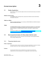
Product description ................................................................................................................................ 15
3.1
Fields of application................................................................................................................... 15
3.2
3.2.1
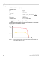
Basic physical principles of a three-phase induction motor....................................................... 15
Three-phase induction motor ..................................................................................................... 15
3.3
3.3.1
3.3.2
3.3.3
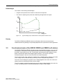
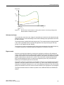
Functional principle of the SIRIUS 3RW30 and 3RW40 soft starters........................................ 17
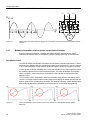
Method of operation of a two-phase controlled soft starter ....................................................... 20
Starting current asymmetry ....................................................................................................... 21
Applications and use ................................................................................................................. 22
3.4
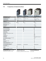
Comparison of device functions ................................................................................................ 24
Product combinations ............................................................................................................................ 25
4.1
5
Important notes.......................................................................................................................... 11
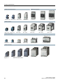
SIRIUS modular system ............................................................................................................ 25
Functions ................................................................................................................................................. 27
5.1
5.1.1
5.1.2
Start modes ............................................................................................................................... 27
Voltage ramp ............................................................................................................................. 27
Current limiting and ramp-up detection (3RW40 only) .............................................................. 29
5.2
5.2.1
5.2.2
Stop modes ............................................................................................................................... 30
Stop without load (3RW30 and 3RW40) .................................................................................... 31
Soft stop (3RW40 only) ............................................................................................................. 31
5.3
5.3.1
5.3.2
Motor protection / intrinsic device protection (3RW40 only) ...................................................... 32
Motor protection function ........................................................................................................... 32
Intrinsic device protection (3RW40 only) ................................................................................... 35
5.4
5.4.1
5.4.2
5.4.3
Functions of the RESET buttons ............................................................................................... 36
SIRIUS 3RW40 2, 3RW40 3, and 3RW40 4 soft starters .......................................................... 36
SIRIUS 3RW40 5 and 3RW40 7 soft starters ............................................................................ 38
Other functions of the RESET button ........................................................................................ 39
5.5
5.5.1
5.5.2
5.5.3
Functions of the inputs .............................................................................................................. 40
Start input (terminal 1) on 3RW30 and 3RW40 2 to 3RW40 4 .................................................. 40
Start input (terminal 3) on 3RW40 5 and 3RW40 7 ................................................................... 40
Thermistor input / connection on 3RW40 2 to 3RW40 4 ........................................................... 41
5.6
5.6.1
5.6.2
Functions of the outputs ............................................................................................................ 41
3RW30: Output terminal 13 / 14 ON .......................................................................................... 41
3RW40: Output terminals 13 / 14 ON / RUN and 23 / 24 BYPASSED ...................................... 42
SIRIUS 3RW30 / 3RW40
Manual 01/2010, 535 1995-02 DS01
5
Table of contents
6
5.6.3
3RW40: Group fault output at terminal 95 / 96 / 98 OVERLOAD / FAILURE ............................ 43
5.7
5.7.1
5.7.2
Diagnostics and fault signals ..................................................................................................... 44
3RW30: LEDs and troubleshooting ........................................................................................... 44
3RW40: LEDs and troubleshooting ........................................................................................... 46
Application planning .............................................................................................................................. 51
6.1
6.1.1
6.1.2
7
Installation ............................................................................................................................................... 53
7.1
7.1.1
7.1.2
7.1.3
7.1.4
7.1.5
8
9
11
6
Installing the soft starter............................................................................................................. 53
Unpacking .................................................................................................................................. 53
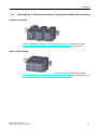
Permissible mounting position ................................................................................................... 53
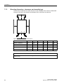
Mounting dimensions, clearances, and assembly type ............................................................. 54
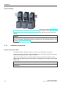
Assembly type: Standalone assembly, side-by-side assembly, direct mounting ....................... 55
Installation requirements ............................................................................................................ 56
Installation / mounting ............................................................................................................................ 57
8.1
General information ................................................................................................................... 57
8.2
Five safety rules for work in or on electrical systems ................................................................ 58
8.3
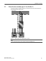
General feeder assembly (type of coordination 1)..................................................................... 59
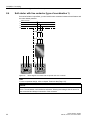
8.4
Soft starter with line contactor (type of coordination 1).............................................................. 60
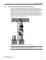
8.5
Soft starter assembly with type of coordination 2 ...................................................................... 61
8.6
Capacitors to improve the power factor ..................................................................................... 62
8.7
Maximum cable length............................................................................................................... 63
Connecting .............................................................................................................................................. 65
9.1
9.1.1
9.1.2
10
Application examples................................................................................................................. 51
Roller conveyor application ........................................................................................................ 51
Hydraulic pump application ........................................................................................................ 52
Electrical connection.................................................................................................................. 65
Control and auxiliary terminals .................................................................................................. 65
Main circuit connection .............................................................................................................. 65
Operation ................................................................................................................................................. 69
10.1
Operator controls, displays, and connections on the 3RW30.................................................... 69
10.2
Operator controls, displays, and connections on the 3RW40.................................................... 70
Configuration .......................................................................................................................................... 73
11.1
11.1.1
11.1.2
Configuration in general............................................................................................................. 73
Configuration procedure ............................................................................................................ 73
Selecting the optimum soft starter ............................................................................................. 74
11.2
11.2.1
11.2.2
Startup class .............................................................................................................................. 76
Application examples for normal starting (CLASS 10) with 3RW30 and 3RW40 ...................... 77
Application examples for heavy-duty starting (CLASS 20): 3RW40 only .................................. 78
11.3
ON time and switching frequency .............................................................................................. 79
11.4
Reducing the rated data ............................................................................................................ 80
11.5
Installation altitude and ambient temperature............................................................................ 80
SIRIUS 3RW30 / 3RW40
Manual, 01/2010, 535 1995-02 DS01
Table of contents
12
11.6
11.6.1
11.6.2
Calculating the permissible switching frequency ....................................................................... 81
Table of permissible assembly combinations with switching frequency factors ........................ 81
Calculating the switching frequency (example) ......................................................................... 84
11.7
11.7.1
11.7.2
11.7.3
11.7.4
Configuration aids...................................................................................................................... 86
Online configurator .................................................................................................................... 86
Win-Soft Starter selection and simulation software ................................................................... 86
Technical Assistance ................................................................................................................. 86
SIRIUS soft starter training course (SD-SIRIUSO) .................................................................... 87
11.8
Order number system for the 3RW30........................................................................................ 88
11.9
Order number system for the 3RW40........................................................................................ 89
Commissioning ....................................................................................................................................... 91
12.1
Before commencing work: Isolating the equipment from the supply system and ensuring that it
cannot be reconnected. ............................................................................................................. 91
12.2
12.2.1
12.2.2
12.2.3
12.2.4
12.2.5
12.2.6
Commissioning the 3RW30 ....................................................................................................... 92
Commissioning procedure ......................................................................................................... 92
Quick commissioning of the 3RW30 and optimization of the parameters ................................. 93
Setting the soft start function ..................................................................................................... 94
Setting the starting voltage ........................................................................................................ 95
Setting the ramp time ................................................................................................................ 95
ON output .................................................................................................................................. 96
12.3
3RW30: LEDs and troubleshooting ........................................................................................... 97
12.4
12.4.1
12.4.2
12.4.3
12.4.4
12.4.5
12.4.6
12.4.7
12.4.8
12.4.9
Commissioning the 3RW40 ....................................................................................................... 98
Commissioning procedure ......................................................................................................... 99
Quick commissioning of the 3RW40 and optimization of the parameters ............................... 100
Setting the soft start function ................................................................................................... 101
Setting the starting voltage ...................................................................................................... 102
Setting the ramp time .............................................................................................................. 102
Current limiting in conjunction with a starting voltage ramp and ramp-up detection ............... 103
Setting the motor current ......................................................................................................... 103
Setting the current limiting value ............................................................................................. 104
Ramp-up detection .................................................................................................................. 104
12.5
12.5.1
Setting the soft stop function ................................................................................................... 105
Setting the ramp-down time ..................................................................................................... 105
12.6
12.6.1
12.6.2
12.6.3
Setting the motor protection function....................................................................................... 105
Setting the electronic motor overload protection ..................................................................... 106
Motor current settings .............................................................................................................. 107
Motor protection acc. to ATEX ................................................................................................. 107
12.7
Thermistor motor protection .................................................................................................... 108
12.8
Motor protection trip test.......................................................................................................... 108
12.9
12.9.1
12.9.2
12.9.3
Functions of the outputs .......................................................................................................... 109
Functions of the BYPASSED and ON / RUN outputs .............................................................. 109
Parameterizing the 3RW40 outputs ......................................................................................... 110
Function of the FAILURE / OVERLOAD output ....................................................................... 112
12.10
RESET MODE and functions of the RESET / TEST button .................................................... 113
12.10.1 SIRIUS 3RW40 2. to 3RW40 4. soft starters ........................................................................... 113
SIRIUS 3RW30 / 3RW40
Manual, 01/2010, 535 1995-02 DS01
7
Table of contents
12.10.2 SIRIUS 3RW40 5. to 3RW40 7. soft starters ........................................................................... 115
12.11
13
Technical data ....................................................................................................................................... 121
13.1
13.1.1
13.1.2
13.1.3
13.1.4
13.1.5
13.1.6
13.1.7
13.1.8
13.1.9
13.1.10
13.1.11
13.1.12
13.1.13
13.1.14
13.1.15
13.1.16
13.1.17
3RW30..................................................................................................................................... 121
Overview .................................................................................................................................. 121
Selection and ordering data for standard applications and normal starting ............................. 122
3RW30..-.BB.. control electronics ............................................................................................ 123
3RW30..-.BB.. control times and parameters .......................................................................... 123
3RW30..-.BB.. power electronics ............................................................................................. 124
3RW30 13, 14, 16, 17, 18-.BB.. power electronics .................................................................. 124
3RW30 26, 27, 28-.BB.. power electronics .............................................................................. 125
3RW30 36, 37, 38, 46, 47-.BB.. power electronics .................................................................. 125
3RW30 main conductor cross-sections ................................................................................... 126
3RW30 auxiliary conductor cross-sections .............................................................................. 127
Electromagnetic compatibility according to EN 60947-4-2 ...................................................... 127
Recommended filters ............................................................................................................... 128
Types of coordination .............................................................................................................. 128
Fuseless version ...................................................................................................................... 129
Fused version (line protection only) ......................................................................................... 130
Fused version with SITOR 3NE1 fuses ................................................................................... 131
Fused version with SITOR 3NE3/4/8 fuses ............................................................................. 132
13.2
13.2.1
13.2.2
13.2.3
3RW40..................................................................................................................................... 134
Overview .................................................................................................................................. 134
Selection and ordering data for standard applications and normal starting (CLASS 10) ......... 135
Selection and ordering data for standard applications and normal starting (CLASS 10) (with
thermistor motor protection evaluation) ................................................................................... 137
Selection and ordering data for standard applications and normal starting (CLASS 10) ......... 139
Selection and ordering data for standard applications and heavy-duty starting (CLASS 20) .. 141
Selection and ordering data for standard applications and heavy-duty starting (CLASS 20) .. 143
3RW40 2., 3., 4. control electronics ......................................................................................... 145
3RW40 5., 7. control electronics .............................................................................................. 145
3RW40 2., 3., 4. control electronics ......................................................................................... 146
3RW40 5., 7. control electronics .............................................................................................. 146
3RW40 protection functions ..................................................................................................... 147
3RW40 control times and parameters ..................................................................................... 147
3RW40 2. to 7. power electronics ............................................................................................ 148
3RW40 24, 26, 27, 28 power electronics ................................................................................. 149
3RW40 36, 37, 38, 46, 47 power electronics ........................................................................... 150
3RW40 55, 56, 73, 74, 75, 76 power electronics ..................................................................... 151
3RW40 2., 3., 4. main conductor cross-sections ..................................................................... 152
3RW40 5., 7. main conductor cross-sections .......................................................................... 153
3RW40 .. auxiliary conductor cross-sections ........................................................................... 154
Electromagnetic compatibility according to EN 60947-4-2 ...................................................... 154
Recommended filters ............................................................................................................... 155
Types of coordination .............................................................................................................. 155
Fuseless version ...................................................................................................................... 156
Fused version (line protection only) ......................................................................................... 157
Fused version with SITOR 3NE1 fuses ................................................................................... 158
Fused version with SITOR 3NE3/4/8 fuses ............................................................................. 159
Motor protection tripping characteristics for 3RW40 (with symmetry) ..................................... 161
13.2.4
13.2.5
13.2.6
13.2.7
13.2.8
13.2.9
13.2.10
13.2.11
13.2.12
13.2.13
13.2.14
13.2.15
13.2.16
13.2.17
13.2.18
13.2.19
13.2.20
13.2.21
13.2.22
13.2.23
13.2.24
13.2.25
13.2.26
13.2.27
8
3RW40: LEDs and troubleshooting ......................................................................................... 117
SIRIUS 3RW30 / 3RW40
Manual, 01/2010, 535 1995-02 DS01
Table of contents
13.2.28 Motor protection tripping characteristics for 3RW40 (with asymmetry) ................................... 161
13.3
14
15
Win-Soft Starter selection and simulation software ................................................................. 162
Dimension drawings ............................................................................................................................. 163
14.1
3RW30 for standard applications ............................................................................................ 163
14.2
3RW40 for standard applications ............................................................................................ 164
Typical circuit diagrams ....................................................................................................................... 167
15.1
Typical circuit for the optional thermistor motor protection evaluation..................................... 167
15.2
15.2.1
15.2.2
Control by pushbutton ............................................................................................................. 168
Control of the 3RW30 by pushbutton ...................................................................................... 168
Control of the 3RW40 by pushbutton ...................................................................................... 169
15.3
15.3.1
15.3.2
Control by switch ..................................................................................................................... 170
Control of the 3RW30 by switch .............................................................................................. 170
Control of the 3RW40 by switch .............................................................................................. 171
15.4
15.4.1
15.4.2
Control in automatic mode....................................................................................................... 172
Control of the 3RW30 in automatic mode ................................................................................ 172
Control of the 3RW40 in automatic mode ................................................................................ 173
15.5
15.5.1
15.5.2
Control by PLC ........................................................................................................................ 175
Control of the 3RW30 with 24 V DC by PLC ........................................................................... 175
Control of the 3RW40 by PLC ................................................................................................. 176
15.6
15.6.1
15.6.2
Control with an optional main / line contactor.......................................................................... 177
Control of the 3RW30 with a main contactor ........................................................................... 177
Control of the 3RW40 with a main contactor ........................................................................... 178
15.7
15.7.1
15.7.2
Reversing circuit ...................................................................................................................... 180
3RW30 reversing circuit .......................................................................................................... 180
3RW40 reversing circuit .......................................................................................................... 181
15.8
15.8.1
15.8.2
15.8.3
Control of a magnetic parking brake........................................................................................ 183
3RW30 motor with magnetic parking brake ............................................................................. 183
3RW40 2 to 3RW40 4, control of a motor with a magnetic parking brake ............................... 184
3RW40 5 to 3RW40 7, control of a motor with a magnetic parking brake ............................... 185
15.9
15.9.1
15.9.2
15.9.3
Emergency stop....................................................................................................................... 186
3RW30 emergency stop and 3TK2823 safety relay ................................................................ 186
3RW40 2 to 3RW40 4 emergency stop and 3TK2823 safety relay ......................................... 187
3RW40 5 to 3RW40 7 emergency stop and 3TK2823 safety relay ......................................... 189
15.10
3RW and contactor for emergency starting ............................................................................. 191
15.10.1 3RW30 and contactor for emergency starting ......................................................................... 191
15.10.2 3RW40 and contactor for emergency starting ......................................................................... 192
15.11
15.11.1
15.11.2
15.11.3
16
Dahlander / multispeed motor ................................................................................................. 194
3RW30 and Dahlander motor starting ..................................................................................... 194
3RW40 2 to 3RW40 4 and Dahlander motor starting .............................................................. 195
3RW40 5 to 3RW40 7 and Dahlander motor starting .............................................................. 197
Accessories ........................................................................................................................................... 199
16.1
Box terminal blocks for soft starters ........................................................................................ 199
16.2
Auxiliary conductor terminals................................................................................................... 199
SIRIUS 3RW30 / 3RW40
Manual, 01/2010, 535 1995-02 DS01
9
Table of contents
A
10
16.3
Covers for soft starters ............................................................................................................ 199
16.4
Modules for RESET ................................................................................................................. 200
16.5
Link modules to 3RV10 motor starter protectors ..................................................................... 201
16.6
Link modules to 3RV20 motor starter protectors ..................................................................... 201
16.7
Optional fan to increase the switching frequency (3RW40 2. to 3RW40 4.)............................ 202
16.8
Spare parts for fans (3RW40 5., 3RW40 7.)............................................................................ 202
16.9
Operating instructions.............................................................................................................. 202
Appendix ................................................................................................................................................ 203
A.1
Configuration data ................................................................................................................... 203
A.2
Table of parameters used........................................................................................................ 205
A.3
Correction sheet ...................................................................................................................... 206
SIRIUS 3RW30 / 3RW40
Manual, 01/2010, 535 1995-02 DS01
Introduction
1.1
1
Important notes
Purpose of the manual
This manual contains fundamental information and practical tips for using SIRIUS soft
starters. The SIRIUS 3RW30 and 3RW40 soft starters are electronic motor control devices
that facilitate optimal starting and stopping three-phase induction motors.
The manual describes all of the functions of the SIRIUS 3RW30 and 3RW40 soft starters.
Target group
This manual is intended for any user involved in
•
Commissioning
•
Servicing and maintaining
•
Planning and configuring systems
Basic knowledge required
A general knowledge of the field of electrical engineering is required to understand this
manual.
Scope of validity
The manual is valid for the SIRIUS 3RW30 and 3RW40 soft starters. It describes the
components that are valid at the time of publication. SIEMENS reserves the right to include a
Product Information for each new component, and for each component of a later version.
Standards and approvals
The SIRIUS 3RW30 and 3RW40 soft starters are based on the IEC/EN 60947-4-2 standard.
Disclaimer of liability
It is the responsibility of the manufacturer to ensure that a system or machine is functioning
properly as a whole. SIEMENS AG, its regional offices, and associated companies
(hereinafter referred to as "SIEMENS") cannot guarantee all the properties of a whole plant
system or machine that has not been designed by SIEMENS.
Similarly, SIEMENS can assume no liability for recommendations that appear or are implied
in the following description. No new guarantee, warranty, or liability claims beyond the scope
of the SIEMENS general terms of supply are to be derived or inferred from the following
description.
SIRIUS 3RW30 / 3RW40
Manual 01/2010, 535 1995-02 DS01
11
Introduction
1.1 Important notes
Orientation aids
The manual contains various features supporting quick access to specific information:
•
At the beginning of the manual you will find a table of contents.
•
A comprehensive index at the end of the manual allows quick access to information on
specific subjects.
Continuously updated information
Your regional contact for low-voltage switchgear with communications capability will be happy
to help you with any queries you have regarding the soft starters. A list of contacts and the
latest version of the manual are available on the Internet at (www.siemens.com/softstarter):
For all technical queries, please contact:
Technical Assistance:
Phone: +49 (0) 911-895-5900 (8°° - 17°° CET) Fax: +49 (0) 911-895-5907
e-mail: (mailto:[email protected])
Internet: (www.siemens.com/lowvoltage/technical-assistance)
Correction sheet
A correction sheet is included at the end of the manual. Please use it to record your
suggestions for improvements, additions, and corrections, and return the sheet to us. This will
help us to improve the next edition of the manual.
12
SIRIUS 3RW30 / 3RW40
Manual, 01/2010, 535 1995-02 DS01
Safety information
2.1
2
Before commencing work: Isolating the equipment from the supply
system and ensuring that it cannot be reconnected.
DANGER
Hazardous voltage Will cause death or serious injury.
• Disconnect the system and all devices from the power supply before starting work.
•
Secure against switching on again.
•
Verify that the equipment is not live.
•
Ground and short-circuit.
•
Erect barriers around or cover adjacent live parts.
DANGER
Hazardous voltage Will cause death or serious injury.
Qualified Personnel.
The equipment / system may only be commissioned and operated by qualified personnel.
For the purpose of the safety information in these Operating Instructions, a "qualified person"
is someone who is authorized to energize, ground, and tag equipment, systems, and circuits
in accordance with established safety procedures.
2.2
Five safety rules for work in or on electrical systems
A set of rules, which are summarized in DIN VDE 0105 as the "five safety rules", are defined
for work in or on electrical systems as a preventative measure against electrical accidents:
1. Isolate
2. Secure against switching on again
3. Verify that the equipment is not live
4. Ground and short-circuit
5. Erect barriers around or cover adjacent live parts
These five safety rules must be applied in the above order prior to starting work on an
electrical system. After completing the work, proceed in the reverse order.
It is assumed that every electrician is familiar with these rules.
SIRIUS 3RW30 / 3RW40
Manual 01/2010, 535 1995-02 DS01
13
Safety information
2.2 Five safety rules for work in or on electrical systems
Explanations
1. The isolating distances between live and deenergized parts of the system must vary
according to the operating voltage that is applied.
"Isolate" refers to the all-pole disconnection of live parts.
All-pole disconnection can be achieved, e.g. by.:
- Switching off the miniature circuit breaker
- Switching off the motor circuit breaker
- Unscrewing fusible links
- Removing LV HRC fuses
2. The feeder must be secured against inadvertent restarting to ensure that it remains
isolated for the duration of the work. This can be achieved, for instance, by securing the
motor and miniature circuit breakers with lockable blocking elements in the disconnected
state, either using a lock or by unscrewing the fuses.
3. The deenergized state of the equipment should be verified using suitable test equipment,
e.g. a two-pole voltmeter. Single-pole test pins are not suitable for this purpose. The
absence of power must be established for all poles, phase to phase, and phase to N/PE.
4. Grounding and short-circuiting are only mandatory if the system has a nominal voltage
greater than 1 kV. In this case, the system should always be grounded first and then
connected to the live parts to be short-circuited.
5. These parts should be covered, or barriers erected around them, to avoid accidental
contact during the work with adjacent parts that are still live.
14
SIRIUS 3RW30 / 3RW40
Manual, 01/2010, 535 1995-02 DS01
Product description
3.1
3
Fields of application
Soft starters are used to start three-phase induction motors with reduced torque and reduced
starting current.
SIRIUS soft starter family
The SIEMENS SIRIUS soft starter family comprises three different versions with different
functionalities and prices.
3RW30 and 3RW40
Simple or standard applications are covered by the SIRIUS 3RW30 and 3RW40 soft starters
and are described in this manual.
3RW44
The SIRIUS 3RW44 soft starter is used if higher functionality is specified, e.g. communication
over PROFIBUS or the availability of measuring and monitoring values, as well as for ultraheavy-duty starting. The SIRIUS 3RW44 soft starter is described in a separate system
manual.
Download from 3RW44 manual (http://support.automation.siemens.com/WW/
llisapi.dll?func=cslib.csinfo&lang=de&objid=21772518&caller=view).
3.2
Basic physical principles of a three-phase induction motor
SIRIUS soft starters are used to reduce the current and torque of a three-phase induction
motor during the startup process.
3.2.1
Three-phase induction motor
Fields of application
Three-phase induction motors are used in a wide range of applications in commerce, industry,
and trade owing to their simple, robust design and their minimal maintenance.
Problem
If a three-phase induction motor is started directly, its typical current and torque
characteristics can cause disturbances in the supply system and the load machine.
SIRIUS 3RW30 / 3RW40
Manual 01/2010, 535 1995-02 DS01
15
Product description
3.2 Basic physical principles of a three-phase induction motor
Starting current
Three-phase induction motors have a high direct starting current Istarting. Depending on the
motor type, this current can be between three and fifteen times as high as the rated
operational current. Seven or eight times the motor's rated current can be assumed as a
typical value.
Disadvantage
This results in the following disadvantage:
•
Higher load on the electrical supply system. The supply system must therefore be
dimensioned for this higher power during the motor startup.
0RWRUFXUUHQW
,
,'LUHFW
RQOLQH
VWDUWLQJ
,1RP
Q1RP
Figure 3-1
0RWRUVSHHG
Q
Typical starting current characteristic of a three-phase induction motor
Starting torque
The starting torque and the breakdown torque can usually be assumed to be between two
and four times the rated torque. From the point of view of the load machine, this means that
the starting and acceleration forces exert a higher mechanical load on the machine and the
product being conveyed compared to nominal operation.
16
SIRIUS 3RW30 / 3RW40
Manual, 01/2010, 535 1995-02 DS01
Product description
3.3 Functional principle of the SIRIUS 3RW30 and 3RW40 soft
Disadvantages
This results in the following disadvantages
•
A higher load is placed on the machine's mechanical components
•
The costs for replacing worn parts and maintaining the application are higher
0RWRU
WRUTXH
0
0VWDOO
0'LUHFWVWDUW
0RWRU
01RP
0$FFHOHUDWLRQ
0/RDG
HJSXPS
Q1RP
Figure 3-2
0RWRUVSHHG
Q
Typical starting torque characteristic of a three-phase induction motor
Remedy
The SIRIUS 3RW30 and 3RW40 electronic soft starters allow the current and torque
characteristics during starting to be optimally adapted to the requirements of each application.
3.3
Functional principle of the SIRIUS 3RW30 and 3RW40 soft starters
The SIRIUS 3RW30 and 3RW40 soft starters have two antiparallel thyristors in two out of the
three phases. One thyristor for the positive half-wave and one for the negative half-wave is
provided in each phase (refer to Fig. "Phase angle control and schematic diagram of a twophase controlled soft starter with integral bypass contacts"). The current in the third,
uncontrolled phase is the sum of the currents in the controlled phases.
The rms value of the motor voltage is increased (from a settable starting voltage) to the rated
motor voltage within a definable ramp-up time by means of the phase angle control.
The motor current changes in proportion to the voltage applied to the motor. As a result, the
starting current is reduced by the factor of this voltage.
There is a quadratic relationship between the torque and the voltage applied to the motor. As
a result, the starting torque is reduced quadratically in relation to this voltage.
SIRIUS 3RW30 / 3RW40
Manual, 01/2010, 535 1995-02 DS01
17
Product description
3.3 Functional principle of the SIRIUS 3RW30 and 3RW40 soft starters
Example
SIEMENS 1LG4253AA motor (55 kW)
Rated data at 400 V
P e:
55 kW
I e:
100 A
Idirect starting:
Approx. 700 A
M e:
355 Nm ; e.g.: Me = 9.55 x 55 kW x
n e:
1480 rpm
Mdirect starting:
Approx. 700 Nm
Set starting voltage:
50 % (½ of mains voltage)
PLQ
=> Istarting ½ of direct starting current (approx. 350 A)
=> Mstarting ¼ of direct starting torque (approx. 175 Nm)
The diagrams below show the starting current and torque characteristics for a three-phase
induction motor in combination with a soft starter:
0RWRUFXUUHQW
,
, 'LUHFW
RQOLQH
VWDUWLQJ
, 6RIWVWDUWHU
, 1RP
Q
Figure 3-3
18
1RP
0RWRUVSHHG
Q
Reduced current characteristic of a three-phase induction motor during starting with a
SIRIUS 3RW30 or 3RW40 soft starter
SIRIUS 3RW30 / 3RW40
Manual, 01/2010, 535 1995-02 DS01
Product description
3.3 Functional principle of the SIRIUS 3RW30 and 3RW40 soft
0RWRUWRUTXH
0
0'LUHFW
RQOLQH
VWDUWLQJ
01RP
06RIWVWDUW
YROWDJHUDPS
Q1RP
0RWRUVSHHG
Q
0/RDGHJSXPS
Figure 3-4
Reduced torque characteristic of a three-phase induction motor during starting with a
SIRIUS 3RW30 or 3RW40 soft starter
Soft start /soft stop
This means that, since the motor voltage is controlled by the electronic soft starter during the
startup process, the consumed starting current and the starting torque generated in the motor
are also controlled.
The same principle is applied during the stop process. This ensures that the torque generated
in the motor is gradually reduced, so that the application can stop smoothly (the soft stop
function is only supported by the 3RW40).
The frequency remains constant during this process and corresponds to the mains frequency,
in contrast to frequency controlled starting and stopping of a frequency converter.
Bypass mode
Once the motor has been started up correctly, the thyristors are subject to fully advanced
control, meaning that the whole mains voltage is applied to the motor terminals. As the motor
voltage does not have to be controlled during operation, the thyristors are bridged by integral
bypass contacts that are rated for AC1 current. This minimizes the waste heat generated
during uninterrupted duty (which is caused by the thyristor's power loss), and minimizes
heating up of the switching device's environment.
The bypass contacts are protected by an integrated, electronic arc quenching system during
operation. If they are opened in the event of a fault, e.g. if the control voltage is temporarily
interrupted, mechanical vibrations occur, or the coil operating mechanism or the main contact
spring has reached the end of its service life and is defective, the equipment is not damaged.
The diagram below shows the method of operation of the SIRIUS 3RW30 and 3RW40 soft
starters:
SIRIUS 3RW30 / 3RW40
Manual, 01/2010, 535 1995-02 DS01
19
Product description
3.3 Functional principle of the SIRIUS 3RW30 and 3RW40 soft starters
/
8
8//
˞
/
˞
˞
/
//
*
˳
0
a
Figure 3-5
3.3.1
Phase angle control and schematic diagram of a two-phase controlled soft starter with integral bypass
contacts
Method of operation of a two-phase controlled soft starter
A special method of operation is used for the SIRIUS 3RW30 and 3RW40 two-phase
controlled soft starters based on SIEMENS' patented "polarity balancing" control principle.
Two-phase control
The SIRIUS 3RW30 and 3RW40 soft starters are two-phase controlled soft starters, in other
words they are designed with two antiparallel thyristors in each of phases L1 and L3. Phase 2
is an uncontrolled phase, which is merely guided through the starter by a copper connection.
In a two-phase controlled soft starter, the current that results from the superimposition of the
two controlled phases flows in the uncontrolled phase. The main advantages of two-phase
control include the more compact size compared to a three-phase version and the lower
hardware costs.
The occurrence of DC components, caused by the phase angle and the overlapping phase
currents, is a negative physical effect of two-phase control during the startup process that can
mean a louder noise is produced by the motor. The "polarity balancing" control principle was
developed and patented by SIEMENS to prevent these DC components during starting.
,$
,$
WV
Figure 3-6
20
,$
WV
WV
Current characteristic and occurrence of DC components in the three phases without "polarity
balancing"
SIRIUS 3RW30 / 3RW40
Manual, 01/2010, 535 1995-02 DS01
Product description
3.3 Functional principle of the SIRIUS 3RW30 and 3RW40 soft
Polarity balancing
"Polarity balancing" effectively eliminates these DC components during the ramp-up phase. It
allows the motor to be started up with a constant speed, torque, and current rise.
The acoustic quality of the startup process comes very close to that of a three-phase
controlled startup. This is made possible by the continuous dynamic alignment and balancing
of current half-waves with different polarities during the motor startup.
,$
,$
WV
Figure 3-7
3.3.2
,$
WV
WV
Current characteristic in the three phases without DC components thanks to "polarity balancing"
Starting current asymmetry
With two-phase control the starting current is asymmetrical for physical reasons, because the
current in the uncontrolled phase is the sum of the currents in the two controlled phases.
This asymmetry can be as much as 30 to 40% during starting (ratio of minimum current to
maximum current in all three phases).
Even though this cannot be influenced, it is not critical in most applications. It could cause an
insufficiently rated fuse to trip in the uncontrolled phase, for instance. For recommended fuse
ratings, refer to the tables in chapter Technical data [Page 121].
,$
,$
WV
Figure 3-8
,$
WV
WV
Starting current asymmetry
SIRIUS 3RW30 / 3RW40
Manual, 01/2010, 535 1995-02 DS01
21
Product description
3.3 Functional principle of the SIRIUS 3RW30 and 3RW40 soft starters
Note
If wye-delta starters are exchanged for soft starters in an existing system, you should check
the fuse ratings in the feeder in order to avoid false tripping. This is particularly important in
connection with heavy-duty starting or if the fuse that is installed has already been operated
close to the thermal tripping limit with the wye-delta assembly.
All elements of the main circuit (such as fuses, motor starter protectors, and switching
devices) must be dimensioned for direct starting and according to the on-site short-circuit
conditions, and ordered separately.
For recommended fuse and motor starter protector ratings for the feeder with soft starter,
refer to chapter Technical data [Page 121].
3.3.3
Applications and use
Applications and selection criteria
The SIRIUS 3RW30 and 3RW40 soft starters represent a good alternative to direct or wyedelta starters.
The most important advantages are:
•
Soft start
•
Soft stop (3RW40 only)
•
Uninterrupted switching without current peaks that place a heavy load on the system
•
Simple installation and commissioning
•
Compact, space-saving design
Applications
The typical applications include:
22
•
Conveyor belts
•
Roller conveyors
•
Compressors
•
Fans
•
Pumps
•
Hydraulic pumps
•
Agitators
•
Circular saws / band saws
SIRIUS 3RW30 / 3RW40
Manual, 01/2010, 535 1995-02 DS01
Product description
3.3 Functional principle of the SIRIUS 3RW30 and 3RW40 soft
Advantages
Conveyor belts and transport systems:
•
Smooth starting
•
Smooth stopping
Rotary pumps and piston pumps:
•
No pressure surges
•
Increased service life of the pipe system
Agitators and mixers:
•
Reduced starting current
Fans:
•
Protection for the gearbox and V belt
SIRIUS 3RW30 / 3RW40
Manual, 01/2010, 535 1995-02 DS01
23
Product description
3.4 Comparison of device functions
3.4
Comparison of device functions
5DWHGFXUUHQWDWr&br&
5DWHGRSHUDWLRQDOYROWDJH
0RWRUUDWLQJDW9bb9
ವ6WDQGDUGFRQQHFWLRQ
ವ,QVLGHGHOWDFLUFXLW
$PELHQWWHPSHUDWXUH
6RIWVWDUWVRIWVWRS
9ROWDJHUDPS
6WDUWLQJVWRSSLQJYROWDJH
5DPSXSDQGUDPSGRZQWLPH
7RUTXHFRQWURO
6WDUWLQJVWRSSLQJWRUTXH
7RUTXHOLPLWLQJ
5DPSWLPH
,QWHJUDWHGMXPSHUFRQWDFWV\VWHP
,QWULQVLFGHYLFHSURWHFWLRQ
0RWRURYHUORDGSURWHFWLRQ
7KHUPLVWRUPRWRUSURWHFWLRQ
,QWHJUDWHGUHPRWH5(6(7
6HWWDEOHFXUUHQWOLPLWLQJ
,QVLGHGHOWDFLUFXLW
%UHDNDZD\WRUTXH
&UHHSVSHHGLQERWKGLUHFWLRQVRIURWDWLRQ
3XPSVWRS
'&EUDNLQJ
&RPELQHGEUDNLQJ
0RWRUKHDWLQJ
&RPPXQLFDWLRQ
([WHUQDOGLVSOD\DQGRSHUDWRUFRQWUROPRGXOH
6WDWXVPHDVXUHGYDOXHGLVSOD\
(UURUORJ
(YHQWVOLVW
0LQPD[SRLQWHUIXQFWLRQ
7UDFHIXQFWLRQ
3URJUDPPDEOHFRQWUROLQSXWVDQGRXWSXWV
1XPEHURISDUDPHWHUVHWV
3DUDPHWHUL]LQJVRIWZDUH6RIW6WDUWHU(6
3RZHUVHPLFRQGXFWRUVWK\ULVWRUV
6FUHZWHUPLQDOV
6SULQJORDGHGWHUPLQDOV
8/&6$
&(PDUN
6RIWVWDUWLQJXQGHUKHDY\GXW\VWDUWLQJ
6XSSRUWIRUFRQILJXUDWLRQ
)XQFWLRQDYDLODEOHದIXQFWLRQQRWDYDLODEOH
)RU5:RQO\VRIWVWDUW
2SWLRQDOXSWRVL]H6GHYLFHYDULDQWV
24
$
9
6,5,865:
6WDQGDUGDSSOLFDWLRQV
N:KS N:KS ದ
r&
6,5,865:
6WDQGDUGDSSOLFDWLRQV
6,5,865:
+LJK)HDWXUHDSSOLFDWLRQV
ದ
ದ
ದ
ದ
ದ
V
V
ದ
ದ
ದ
ದ
ದ
ದ
ದ
ದ
ದ
ದ
ದ
ದ
ದ
ದ
ದ
ದ
ದ
ದ
ದ
ದ
ದ
ದ
ದ
ದ
ದ
FRQWUROOHGSKDVHV
ದ
ದ
ದ
ದ
ದ
ದ
ದ
ದ
ದ
ದ
ದ
ದ
ದ
ದ
ದ
ದ
FRQWUROOHGSKDVHV
:LWK352),%86'3RSWLRQ
RSWLRQ
FRQWUROOHGSKDVHV
ದ
ದ
:LQ6RIW6WDUWHUHOHFWURQLFVHOHFWLRQVOLGHU7HFKQLFDO$VVLVWDQFH
)RU5:WR5:IRU
1RWSRVVLEOHLQLQVLGHGHOWDFLUFXLW
5:DQG5:RSWLRQDO
7UDFHIXQFWLRQZLWK6RIW6WDUWHU(6VRIWZDUH
,IQHFHVVDU\RYHUGLPHQVLRQVRIWVWDUWHUDQGPRWRU
$FFWR$7(;
SIRIUS 3RW30 / 3RW40
Manual, 01/2010, 535 1995-02 DS01
Product combinations
4.1
4
SIRIUS modular system
Switching, protecting, and starting motors
In order to simplify the assembly of load feeders, the SIRIUS modular system offers standard
components that are optimally harmonized and are easy to combine. Just 7 sizes cover the
entire performance range up to 250 kW / 300 hp. The individual switching devices can be
assembled to form complete load feeders, either using link modules or by mounting directly.
For a selection of matching device combinations, e.g. soft starters and motor starter
protectors, refer to chapter Technical data [Page 121].
For further information on individual products, refer to System manual (http://
support.automation.siemens.com/WW/
llisapi.dll?aktprim=0&lang=en&referer=%2fWW%2f&func=cslib.csinfo&siteid=csius&caller=vi
ew&extranet=standard&viewreg=WW&nodeid0=20025979&objaction=csopen) "Innovations
in the SIRIUS modular system", Order No. 3ZX1012-0RA01-1AB1.
SIRIUS 3RW30 / 3RW40
Manual 01/2010, 535 1995-02 DS01
25
Product combinations
4.1 SIRIUS modular system
6,5,86PRWRUVWDUWHUSURWHFWRUV
596 596
6(17521FLUFXLWEUHDNHUV
596
596
9/9/
9/9/
9/9/
6,5,86FRQWDFWRUV
576
576
576
576
576
5%6
5%6
5%6
5:6
5:6
5:6
576
576
6,5,86RYHUORDGUHOD\V
5%6
5%6
5%66
6,5,86VRIWVWDUWHUV
5:6
Figure 4-1
26
5:6
5:66
SIRIUS modular system
SIRIUS 3RW30 / 3RW40
Manual, 01/2010, 535 1995-02 DS01
Functions
5.1
5
Start modes
You can choose between different startup functions reflecting the wide range of applications
and functionality of the SIRIUS 3RW30 and 3RW40 soft starters. The motor start can be
optimally adapted to each particular application.
5.1.1
Voltage ramp
The SIRIUS 3RW30 and 3RW40 soft starters achieve soft starting by means of a voltage
ramp. The motor terminal voltage is increased from a parameterizable starting voltage up to
the mains voltage within a definable ramp-up time.
Starting voltage
The starting voltage determines the starting torque of the motor. A lower starting voltage
results in a lower starting torque and a lower starting current. The starting voltage selected
must be sufficiently high to ensure that motor starts up smoothly as soon as the start
command is received by the soft starter.
Ramp time
The length of the set ramp time determines the time taken to increase the motor voltage from
the parameterized starting voltage to the mains voltage. This influences the motor's
acceleration torque, which drives the load during the ramp-up process. A longer ramp time
results in a lower acceleration torque as the motor is started up. The startup is slower and
smoother as a result. The ramp time should be long enough for the motor to reach its nominal
speed. If the time selected is too short, in other words if the ramp time ends before the motor
has started up successfully, a very high starting current that can even equal the direct starting
current at the same speed occurs at this instant.
The SIRIUS 3RW40 soft starter limits the current to the value set with the current limiting
potentiometer (refer to chapter Current limiting and ramp-up detection (3RW40 only) [Page
29]). As soon as the current limiting value is also reached, the voltage ramp or the ramp time
is interrupted and the motor is started with the current limiting value until it has started up
successfully. In this case, the motor ramp-up time may be longer than the maximum
parameterizable 20 seconds ramp time (for further information about the maximum ramp-up
times and switching frequencies, refer to chapter 3RW40 2. to 7. power electronics [Page
148] ff).
The SIRIUS 3RW40 soft starter has intrinsic device protection, current limiting, and ramp-up
detection functions. These functions do not form part of the SIRIUS 3RW30 soft starter.
SIRIUS 3RW30 / 3RW40
Manual 01/2010, 535 1995-02 DS01
27
Functions
5.1 Start modes
CAUTION
Risk of property damage
When using the 3RW30: Make sure the selected ramp time is longer than the actual motor
ramp-up time. If not, the SIRIUS 3RW30 may be damaged because the internal bypass
contacts close when the set ramp time elapses. If the motor has not finished starting up, an
AC3 current that could damage the bypass contact system will flow.
When using the 3RW40: The 3RW40 has an integrated ramp-up detection function that
prevents this operating state from occurring.
The maximum ramp time for the SIRIUS 3RW30 soft starter is 20 seconds An appropriately
dimensioned SIRIUS 3RW40 or 3RW44 soft starter should be chosen for startup processes
with a motor ramp-up time > 20 seconds.
9ROWDJHLQ
80RWRU
3DUDPHWHUL]DEOH
VWDUWYROWDJH
3DUDPHWHUL]DEOH
VWDUWLQJWLPH
6KRUWVWDUWLQJWLPH
/RQJHUVWDUWLQJWLPH
Figure 5-1
9ROWDJHDW
WKHPRWRU
7LPHW
V
Principle of the voltage ramp
0RWRUWRUTXH0
1P
0'LUHFWRQOLQHVWDUWLQJ
PD[LPXPWRUTXH
WKDWFDQEHJHQHUDWHG
01RP
3DUDPHWHUL]DEOH
VWDUWYROWDJH
$FFHOHUDWLRQ
WRUTXH
6SHHGQ
PLQ
06RIWVWDUW
6KRUWUDPSWLPH
06RIWVWDUW
3DUDPHWHUL]DEOH
WRUTXHVWDUWLQJWLPH
0RWRUKDVUXQXSDQGLV
LQQRPLQDORSHUDWLRQQ1RP
/RQJHUUDPSWLPH
0/RDGHJ)DQ
Figure 5-2
28
Principle of the voltage ramp for the torque characteristic
SIRIUS 3RW30 / 3RW40
Manual, 01/2010, 535 1995-02 DS01
Functions
5.1 Start modes
0RWRUFXUUHQW,
$
,'LUHFW
RQOLQH
VWDUWLQJ
,6RIWVWDUWHU
,1RP
Q1RP 0RWRUVSHHG
Q
,6RIWVWDUWHU
3DUDPHWHUL]DEOH
UDPSWLPH
6KRUWUDPSWLPH
,6RIWVWDUWHU
/RQJHUUDPSWLPH
Figure 5-3
Principle of the voltage ramp for the starting current characteristic
Typical applications of the voltage ramp
The voltage ramp principle is valid for all applications, e.g. pumps, compressors, conveyor
belts.
5.1.2
Current limiting and ramp-up detection (3RW40 only)
The SIRIUS 3RW40 soft starter measures the phase current (motor current) continuously with
the help of integrated current transformers.
The motor current that flows during the startup process can be actively limited by means of
the soft starter. The current limiting function takes priority over the voltage ramp function. As
soon as a parameterizable current limit is reached, in other words, the voltage ramp is
interrupted and the motor is started with the current limiting value until it has started up
successfully. The current limiting function is always active with SIRIUS 3RW40 soft starters. If
the current limiting potentiometer is set to the clockwise stop (maximum), the starting current
is limited to five times the set rated motor current.
Current limiting value
The current limiting value is set to the current required during starting as a factor of the rated
motor current. Since the starting current is asymmetrical, the set current corresponds to the
arithmetic mean value for the three phases.
Example
If the current limiting value is set to 100 A, the currents might be approx. 80 A in L1, 120 A in
L2, and 100 A in L3 (refer to chapter Starting current asymmetry [Page 21]).
SIRIUS 3RW30 / 3RW40
Manual, 01/2010, 535 1995-02 DS01
29
Functions
5.2 Stop modes
As soon as the selected current limiting value is reached, the motor voltage is reduced or
controlled by the soft starter to prevent the current from exceeding the limit. The set current
limiting value must be high enough to ensure that the torque generated in the motor is
sufficient to accelerate the motor to nominal speed. Three to four times the value of the
motor's rated operational current (Ie) can be assumed as typical here.
The current limiting function is always active because it is required by the intrinsic device
protection. If the current limiting potentiometer is set to the clockwise stop (maximum), the
starting current is limited to five times the set rated motor current.
Ramp-up detection (3RW40 only)
The SIRIUS 3RW40 soft starter is equipped with an integrated ramp-up detection function. If it
detects a motor startup, the motor voltage is immediately increased to 100 % of the mains
voltage. The internal bypass contacts close and the thyristors are bridged.
0RWRUFXUUHQW
,
,'LUHFW
RQOLQH
VWDUWLQJ
PRWRU
,6RIWVWDUWHU
DGMXVWDEOHFXUUHQW
OLPLWYDOXH
%HJLQQLQJGHWHU
PLQHGE\VSHFLILHG
VWDUWLQJPRGHLQWKLV
FDVHYROWDJHUDPS
0RWRUUXQXS
UHFRJQL]HG
E\SDVVFRQWDFWV
FORVH
,H0RWRU
QH0RWRU
Figure 5-4
0RWRUVSHHG
Q
Current limiting with soft starter
Typical applications for current limiting
Current limiting is used for applications with large centrifugal masses (mass inertias) and
therefore longer ramp-up times, e.g. fans, circular saws etc.
5.2
Stop modes
You can choose between different stop modes reflecting the wide range of applications for
SIRIUS soft starters. The motor stop can be optimally adapted to each particular application.
If a start command is issued during the stop process, the process is interrupted and the motor
is started again with the set start mode.
Note
If you select "soft stop" (3RW40 only) as the stop mode, the feeder (soft starter, cables,
feeder protective devices, and motor) may need to be dimensioned for higher values
because the current exceeds the rated motor current during the stop process.
30
SIRIUS 3RW30 / 3RW40
Manual, 01/2010, 535 1995-02 DS01
Functions
5.2 Stop modes
0RWRU
VSHHG
Q
QH
1 Q&RDVWLQJGRZQ
2 Q7RUTXHFRQWUROOHG
6WRSFRPPDQG
DWVRIWVWDUWHU
7LPHW
V
VWRSSLQJPRGH
5.2.1
Stop without load (3RW30 and 3RW40)
"Stop without load" means the power supplied to the motor via the soft starter is interrupted
when the ON command is removed from the starter. The motor coasts to a standstill, driven
only by the mass inertia (centrifugal mass) of the rotor and load. This is also referred to as a
natural stop. A large centrifugal mass means a longer stop time without load.
Typical applications for stop without load
Stop without load is used for loads that place no special demands on the startup
characteristic, e.g. fans.
5.2.2
Soft stop (3RW40 only)
In "soft stop" mode, the natural stop process of the load is decelerated. The function is used
when the load must be prevented from stopping abruptly. This is typically the case in
applications with a low mass inertia or a high counter-torque.
Ramp-down time
The "Ramp-down time" potentiometer on the soft starter allows you to specify how long power
should still be supplied to the motor after the ON command is removed. The torque generated
in the motor is reduced by means of a voltage ramp function within this ramp-down time and
the application stops smoothly.
If the motor is stopped abruptly in pump applications, as is normal with wye-delta or direct
starting, for instance, water hammer can occur. Water hammer is caused by the sudden flow
separation, leading to pressure fluctuations on the pump. It has the effect of producing noise
and mechanical impacts on the pipelines as well as on any flaps and valves installed there.
SIRIUS 3RW30 / 3RW40
Manual, 01/2010, 535 1995-02 DS01
31
Functions
5.3 Motor protection / intrinsic device protection (3RW40 only)
Water hammer can be reduced compared to direct or wye-delta starting by using the SIRIUS
3RW40 soft starter. An optimum pump stop is achieved using a SIRIUS 3RW44 soft starter
with an integrated pump stop function (refer to chapter Comparison of device functions [Page
24]).
0RWRU
WRUTXH
0
01RPLQDO
RSHUDWLRQ
6WRSSLQJWLPH
7LPHW
V
6WRSFRPPDQG
DWVRIWVWDUWHU
Typical applications for soft stop
Use soft stop for
5.3
•
Pumps to reduce water hammer.
•
Conveyor belts to prevent the conveyed product from tilting.
Motor protection / intrinsic device protection (3RW40 only)
NOTICE
If the soft starter is disconnected because the motor overload protection or the intrinsic
device protection trips, you must wait a defined cooling time (recovery time) prior to
acknowledging the fault or starting the motor again. (Motor overload tripping time: 60
seconds, temperature sensor: after cooling, intrinsic device protection tripping time: >
30 seconds)
5.3.1
Motor protection function
The motor overload protection function is implemented on the basis of the winding
temperature. This indicates whether the motor is overloaded or functioning in the normal
operating range.
The winding temperature can either be calculated with the help of the integrated, electronic
motor overload function or measured with a connected motor thermistor.
32
SIRIUS 3RW30 / 3RW40
Manual, 01/2010, 535 1995-02 DS01
Functions
5.3 Motor protection / intrinsic device protection (3RW40 only)
The two types of protection must be combined to achieve full motor protection. This
combination is recommended to protect the motor optimally.
Note
Thermistor motor protection evaluation
The thermistor motor protection evaluation function is optionally available for the SIRIUS
3RW40 2 to 3RW40 4 soft starters in the 24 V AC/DC control voltage version.
Motor overload protection
The current flow during motor operation is measured by measuring the current with
transformers integrated in the soft starter. The temperature rise in the winding is calculated
based on the rated operational current set for the motor.
A trip is generated by the soft starter when the characteristic is reached, depending on the trip
class (CLASS setting).
ATEX
"Increased safety" type of protection EEx e acc. to ATEX Directive 94/9/EC
The SIRIUS 3RW40 soft starter sizes S0 to S12 are suitable for starting explosion-proof
motors with the "increased safety" type of protection EEx e (type of protection / marking: Ex II
(2) GD).
Wire the fault output (95 96) to an upstream switching device in such a way that if a fault
occurs, this device disconnects the feeder (refer to Fig. "3RW40 wiring fault with 3RV").
//
1/
)
21
57
4
5:
$ $ ,1
5:
0
a
Figure 5-5
SIRIUS 3RW30 / 3RW40
Manual, 01/2010, 535 1995-02 DS01
$
4
$
3RW40 wiring fault
33
Functions
5.3 Motor protection / intrinsic device protection (3RW40 only)
//
1/
21
4
,!
59
5:
$ $ ,1
5:
0
a
Figure 5-6
'
8
'
3RW40 wiring fault with 3RV
4
For further information, refer to the operating instructions, Order No. 3ZX1012-0RW40-1CA1
(http://support.automation.siemens.com/WW/view/de/22809303).
WARNING
Danger of death or serious injury.
The 3RW40 is not suitable for installation in hazardous areas. The device is only allowed to
be installed in a control cabinet with the IP4x degree of protection. Appropriate measures
(e.g. encapsulation) must be taken if it is to be installed in a hazardous area.
Trip class (electronic overload protection)
The trip class (CLASS) specifies the maximum time within which a protective device must trip
from a cold state at 7.2 x the rated operational current (motor protection to IEC 60947). The
tripping characteristics represent this time as a function of the tripping current (refer to
chapter Motor protection tripping characteristics for 3RW40 (with symmetry) [Page 161]).
You can set different CLASS characteristics according to the startup class.
Note
The rated data of the soft starters refers to normal starting (CLASS 10). The starters may
need to be calculated with a size allowance for heavy-duty starting (> CLASS 10). You can
only set a rated motor current that is lower than the soft starter rated current (for the
permissible settings, refer to chapter Technical data [Page 121]).
Recovery time (motor overload protection)
A recovery time of 60 seconds, during which the motor cools down and cannot be restarted,
starts if the thermal motor model is tripped.
34
SIRIUS 3RW30 / 3RW40
Manual, 01/2010, 535 1995-02 DS01
Functions
5.3 Motor protection / intrinsic device protection (3RW40 only)
Protection against voltage failure in the event of a fault
If the control supply voltage fails during a trip, the current tripping state of the thermal motor
model and the current recovery time are stored in the soft starter. When the control supply
voltage is restored, the current tripping state of the thermal motor model and the intrinsic
device protection prior to the power failure are likewise automatically restored. If the control
voltage is disconnected during operation (without a preceding fault trip), the starter is not
protected against voltage failure.
Temperature sensor
Note
Temperature sensor
The temperature sensor evaluation function is optionally available for the SIRIUS 3RW40 24
to 3RW40 47 soft starters in the 24 V AC/DC control voltage version.
This motor protection function measures the motor's stator winding temperature directly with
the help of a sensor installed in the motor, in other words the motor must have a sensor
wound into the stator winding.
You can choose between two different sensor types for the evaluation.
1. Type A PTC thermistors ("type A sensors") for connection to terminals T11/21 and T12
2. Thermoclick sensors for connection to terminals T11/21 and T22
The wiring and sensors are monitored for wire breakage and short-circuits.
Recovery time (thermistor motor protection)
If the thermistor motor protection is tripped, the soft starter cannot be restarted until the
sensor installed in the motor has cooled down. The recovery time varies according to the
temperature state of the sensor.
5.3.2
Intrinsic device protection (3RW40 only)
Thyristor protection (thermal)
SIRIUS 3RW40 soft starters are equipped with integrated intrinsic device protection to
prevent thermal overloading of the thyristors.
This is achieved on the one hand by means of current measuring transformers in the three
phases and on the other, by measuring the temperature with temperature sensors on the
thyristor's heat sink.
If the fixed, internally set trip value is exceeded, the soft starter is automatically disconnected.
Recovery time (intrinsic device protection)
If the intrinsic device protection is tripped, the soft starter cannot be restarted until a recovery
time of at least 30 seconds has elapsed.
SIRIUS 3RW30 / 3RW40
Manual, 01/2010, 535 1995-02 DS01
35
Functions
5.4 Functions of the RESET buttons
Thyristor protection (short-circuit)
SITOR semiconductor fuses must be connected upstream to protect the thyristors against
short-circuits (e.g. in case of cable damage or an interturn fault in the motor; refer to chapter
Soft starter assembly with type of coordination 2 [Page 61]). For the fuse selection tables,
refer to chapter Technical data [Page 121].
Protection against voltage failure (in the event of a fault)
If the control supply voltage fails during a trip, the current tripping state of the thermal intrinsic
device protection model and the current recovery time are stored in the soft starter. When the
control supply voltage is restored, the current tripping state of the thermal intrinsic device
protection prior to the power failure are likewise automatically restored.
NOTICE
If the control voltage is disconnected during operation (e.g. in "automatic mode"), the starter
is not protected against voltage failure. You must wait five minutes between two starts to
ensure that the motor protection and the intrinsic device protection are working correctly.
5.4
Functions of the RESET buttons
5.4.1
SIRIUS 3RW40 2, 3RW40 3, and 3RW40 4 soft starters
5.4.1.1
RESET MODE button and LED
By pressing the RESET MODE button, you define the reset procedure in case of a fault. This
is indicated by the RESET MODE LED.
Yellow = AUTO
Off = MANUAL
Green = REMOTE
Note
On the SIRIUS 3RW40 2. soft starter, the RESET MODE button is located underneath the
label (refer to chapter Operator controls, displays, and connections on the 3RW40 [Page 70])
36
SIRIUS 3RW30 / 3RW40
Manual, 01/2010, 535 1995-02 DS01
Functions
5.4 Functions of the RESET buttons
5.4.1.2
Manual RESET
Manual RESET with the RESET / TEST button (RESET MODE LED = off)
You can reset a fault by pressing the RESET / TEST button.
5.4.1.3
Remote RESET
Remote RESET (RESET MODE LED = green)
You can reset a fault signal by disconnecting the control supply voltage for >1.5 s.
1/ //
5(6(7
212))
8V
$ $ ! V
W
5.4.1.4
AUTO RESET
AUTO RESET (RESET MODE LED = yellow)
If you set the RESET mode to AUTO, a fault is automatically reset as follows:
•
If the motor overload protection function trips: after 60 s
•
If the intrinsic device protection function trips: after 30 s
•
If the thermistor evaluation function trips: after the temperature sensor in the motor has
cooled down
WARNING
Automatic restart
Danger of death, serious injury, or property damage.
The automatic RESET mode (AUTO RESET) must not be used in applications where
there is a risk of serious injury to persons or substantial damage to property if the motor
starts up again unexpectedly. The start command (e.g. issued by a contact or the PLC)
must be reset prior to issuing a RESET command because the motor attempts to restart
again automatically following this RESET command if a start command is still present.
This particularly applies if the motor protection has tripped. For safety reasons, you are
advised to integrate the group fault output (terminals 95 and 96) in the controller.
5.4.1.5
Acknowledging faults
For information about whether or not faults can be acknowledged as well as the
corresponding LED and output contact states, refer to chapter Diagnostics and fault signals
[Page 44].
SIRIUS 3RW30 / 3RW40
Manual, 01/2010, 535 1995-02 DS01
37
Functions
5.4 Functions of the RESET buttons
5.4.2
SIRIUS 3RW40 5 and 3RW40 7 soft starters
5.4.2.1
RESET MODE button and AUTO LED
By pressing the RESET MODE button, you define the reset procedure in case of a fault. This
is indicated by the AUTO LED.
Yellow = AUTO
Off = MANUAL (REMOTE)
5.4.2.2
Manual RESET
Manual RESET with the RESET / TEST button (AUTO LED = off)
You can reset a fault by pressing the RESET / TEST button.
5.4.2.3
Remote RESET
Remote RESET (AUTO LED = green)
You can initiate a remote RESET by controlling the optional module for RESET (3RU19002A).
1
/ / /
)
1
/
)
7HVW 5HVHW
6
VHF
8 9:
0
38
0
a
(
(
58$)HUQUHVHW5HPRWH5HVHW
SIRIUS 3RW30 / 3RW40
Manual, 01/2010, 535 1995-02 DS01
Functions
5.4 Functions of the RESET buttons
5.4.2.4
AUTO RESET
AUTO RESET (AUTO LED = yellow)
If you set the RESET mode to AUTO, a fault is automatically reset as follows:
•
If the motor overload protection function trips: after 60 s
•
If the intrinsic device protection function trips: after 30 s
WARNING
Automatic restart
Can result in death, serious injury, or property damage.
The automatic RESET mode (AUTO RESET) must not be used in applications where
there is a risk of serious injury to persons or substantial damage to property if the motor
starts up again unexpectedly. The start command (e.g. issued by a contact or the PLC)
must be reset prior to issuing a RESET command because the motor attempts to restart
again automatically following this RESET command if a start command is still present.
This particularly applies if the motor protection has tripped. For safety reasons, you are
advised to integrate the group fault output (terminals 95 and 96) in the controller.
5.4.2.5
Acknowledging faults
For information about whether or not faults can be acknowledged as well as the
corresponding LED and output contact states, refer to chapter Diagnostics and fault signals
[Page 44].
5.4.3
Other functions of the RESET button
5.4.3.1
Motor protection trip test
You initiate a motor overload trip by pressing the RESET / TEST button for longer than five
seconds. The SIRIUS 3RW40 soft starter is tripped by the fault signal at the OVERLOAD
LED, the FAILURE / OVERLOAD contact 95-98 closes, and the motor that is connected and
running is switched off.
RESET / TEST button on the 3RW40 2,
3RW40 3, and 3RW40 4
5.4.3.2
RESET / TEST button on the 3RW40 5 and
3RW40 7
Reparameterizing the ON / RUN output contact
For information about reparameterizing the output with the RESET / TEST button, refer to
chapter Parameterizing the 3RW40 outputs [Page 110] .
SIRIUS 3RW30 / 3RW40
Manual, 01/2010, 535 1995-02 DS01
39
Functions
5.5 Functions of the inputs
5.5
Functions of the inputs
5.5.1
Start input (terminal 1) on 3RW30 and 3RW40 2 to 3RW40 4
Rated control voltage is present at terminal A1 / A2: The startup process of the soft starter
begins when a signal is present at terminal 1 (IN). The starter operates until the signal is
removed again.
If a ramp-down time is parameterized (3RW40 only), a soft stop starts as soon as the signal is
removed.
The potential of the signal at terminal 1 must correspond to the potential of the rated control
voltage at terminal A1 / A2.
For recommended circuits, e.g. control by means of pushbuttons, contactor contacts, or a
PLC, refer to chapter Typical circuit diagrams [Page 167].
5.5.2
Start input (terminal 3) on 3RW40 5 and 3RW40 7
Rated control voltage is present at terminal A1 / A2: The startup process of the soft starter
begins when a signal is present at terminal 3 (IN). The starter operates until the signal is
removed again. If a ramp-down time is parameterized, a soft stop starts as soon as the signal
is removed.
The 24 V DC control voltage supplied by the soft starter must be taken from terminal 1 (+) as
voltage for the signal at terminal 3.
If you select direct control by a PLC, the "M" of the PLC's reference potential must be
connected to terminal 2 (-).
$
$
9
+]
GFFG ,1
9
For recommended circuits, e.g. control by means of pushbuttons, contactor contacts, or a
PLC, refer to chapter Typical circuit diagrams [Page 167].
40
SIRIUS 3RW30 / 3RW40
Manual, 01/2010, 535 1995-02 DS01
Functions
5.6 Functions of the outputs
5.5.3
Thermistor input / connection on 3RW40 2 to 3RW40 4
24 V AC/DC rated control voltage
After removing the copper jumper between T11/21 and T22, you can connect and evaluate
either a Klixon thermistor integrated in the motor winding (at terminal T11/T21-T22) or a type
A PTC (at terminal T11/T21-T12).
T11/T21
T11/T21 T12 T22
ϑ
ϑ
Klixon
5.6
Functions of the outputs
5.6.1
3RW30: Output terminal 13 / 14 ON
T12 T22
Type A PTC
The potential-free output contact at terminal 13/14 (ON) closes if a signal is present at
terminal 1 (IN); it remains closed until the start command is removed.
The output can be used, for instance, to control a line contactor connected upstream or to
implement latching if you selected pushbutton control. For recommended circuits, refer to
chapter Typical circuit diagrams [Page 167].
IN
1
tR on
UN
t
U
US
tR on
ON
13/14
tR on
SIRIUS 3RW30 / 3RW40
Manual, 01/2010, 535 1995-02 DS01
t
t
41
Functions
5.6 Functions of the outputs
For a state diagram of the contact in the various operating states, refer to chapter Diagnostics
and fault signals [Page 44].
5.6.2
3RW40: Output terminals 13 / 14 ON / RUN and 23 / 24 BYPASSED
ON
The potential-free output contact at terminal 13/14 (ON) closes if a signal is present at
terminal 1 (IN); it remains closed until the start command is removed (factory default). The ON
function can be used, for instance, as a latching contact if you selected pushbutton control.
Reparameterizing from ON to RUN
You can reparameterize the function of the ON output on the 3RW40 to RUN by
simultaneously pressing the RESET TEST and RESET MODE buttons (refer to chapter
Commissioning the 3RW40 [Page 98]).
RUN
The RUN output remains closed as long as the motor is controlled by the soft starter, in other
words during the startup phase, in bypass mode, and during the soft stop (if set). This output
function can be used, for instance, if a line contactor connected upstream must be controlled
by the soft starter, especially if the soft stop function is set.
BYPASSED
The BYPASSED function can be used, for instance, to indicate that the motor has started up
successfully.
The BYPASSED output at terminal 23 / 24 closes as soon as the SIRIUS 3RW40 soft starter
detects that the motor has started up (refer to chapter Ramp-up detection [Page 104]).
The integral bypass contacts simultaneously close and the thyristors are bridged. The integral
bypass contacts and output 23 / 24 open again as soon as the start input IN is removed.
42
SIRIUS 3RW30 / 3RW40
Manual, 01/2010, 535 1995-02 DS01
Functions
5.6 Functions of the outputs
IN
13/14
tR on
UN
tR off
t
tR off
t
tR off
t
U
US
tR on
ON 13/14
RUN 13/14
BYPASSED 23/24
tR on
For a state diagram of the contacts and the LEDs in the various operating and fault states,
refer to chapter Diagnostics and fault signals [Page 44].
For recommended circuits, refer to chapter Typical circuit diagrams [Page 167].
5.6.3
3RW40: Group fault output at terminal 95 / 96 / 98 OVERLOAD / FAILURE
If there is no rated control voltage or if a failure occurs, the potential-free FAILURE /
OVERLOAD output is switched.
For recommended circuits, refer to chapter Typical circuit diagrams [Page 167].
For a state diagram of the contacts in the various fault and operating states, refer to chapter
Diagnostics and fault signals [Page 44].
SIRIUS 3RW30 / 3RW40
Manual, 01/2010, 535 1995-02 DS01
43
Functions
5.7 Diagnostics and fault signals
5.7
Diagnostics and fault signals
5.7.1
3RW30: LEDs and troubleshooting
/('VRQ5:
6RIWVWDUWHU
'(9,&(
UGJQ\OZ
5:
$X[LOLDU\FRQWDFW
67$7(%<3$66('
)$,/85(
JQUG
21
8V 2SHUDWLQJVWDWH
,1
2II
JQ
6WDUW
JQ
%\SDVVHG
JQ
JQ
JQ
)DXOW
,PSHUPLVVLEOHHOHFWURQLFVVXSSO\
YROWDJH
%\SDVVRYHUORDG
UG
0LVVLQJORDGYROWDJH
3KDVHIDLOXUHPLVVLQJORDG
'HYLFHIDXOW
\OZ
UG
JQ
UG
UG
UG
/('V
2II
21
)ODVKLQJ
JQ
UG
\OZ
*UHHQ
5HG
<HOORZ
1) The fault is automatically reset by an outgoing event. An automatic restart is initiated and
the 3RW restarted if a start command is present at the input.
WARNING
Automatic restart
Danger of death, serious injury, or property damage.
If you do not want the motor to start automatically, you must integrate suitable additional
components, e.g. phase failure or load monitoring devices, into the control and main circuits.
2) The fault can be acknowledged by removing the start command at the start input.
3) Switch off the control voltage, then switch it on again. If the fault is still present, contact
your SIEMENS partner or Technical Assistance.
For notes on troubleshooting, refer to the table below.
44
SIRIUS 3RW30 / 3RW40
Manual, 01/2010, 535 1995-02 DS01
Functions
5.7 Diagnostics and fault signals
Fault
Cause
Remedy
Impermissible electronics supply
voltage
The control supply voltage does not
correspond to the soft starter's rated
voltage.
Check the control supply voltage; an
incorrect control supply voltage could be
caused by a power failure or a voltage
dip.
Bypass overload
A current > 3.5 x Ie of the soft starter
occurs for > 60 ms in bypass mode (e.g.
because the motor is blocked).
Check the motor and load, and check the
soft starter's dimensions.
Missing load voltage, phase failure
/ missing load
Cause 1: Phase L1 / L2 / L3 is missing or
fails / collapses when the motor is
operating.
Connect L1 / L2 / L3 or correct the voltage
dip.
Tripped as a result of a dip in the
permissible rated operational voltage >
15 % for > 100 ms during the startup
process or > 200 ms in bypass mode.
Device fault
SIRIUS 3RW30 / 3RW40
Manual, 01/2010, 535 1995-02 DS01
Cause 2: The motor that is connected is
too small and the fault occurs as soon as
it is switched to bypass mode.
If less than 10 % of the soft starter's rated
current is flowing, the motor cannot be
operated with soft starter. Use another
soft starter.
Cause 3: Motor phase T1 / T2 / T3 is not
connected.
Connect the motor properly (e.g. jumpers
in the motor terminal box, repair switch
closed etc.)
Soft starter defective.
Contact your SIEMENS partner or
Technical Assistance.
45
Functions
5.7 Diagnostics and fault signals
5.7.2
3RW40: LEDs and troubleshooting
/('VRQ5:
$X[LOLDU\FRQWDFWV
0RWRUSURWHFWLRQ
6RIWVWDUWHU
67$7(
5(6(7
02'(
%<3$66('
29(5/2$' $872
'(9,&(
)$,/85(
UG
\OZJQ
UGJQ\OZ JQUG
5:
21
581
)$,/85(
%<3$66(' 29(5/2$'
8V 2SHUDWLQJVWDWH
,1
2II
JQ
6WDUW
JQ
JQ
%\SDVVHG
JQ
JQ
6WRS
JQ
JQ
:DUQLQJ
,HLPSHUPLVVLEOH&/$66VHWWLQJ
JQ
6WDUWLQKLELWHGGHYLFHWRRKRWFRROLQJWLPH PD\YDU\DFFRUGLQJWRWK\ULVWRUWHPSHUDWXUH
JQ JQ
\OZ
)DXOW
,PSHUPLVVLEOHHOHFWURQLFVVXSSO\
YROWDJH
UG
,PSHUPLVVLEOH,H&/$66VHWWLQJDQG,1
!
0RWRUSURWHFWLRQWULSSLQJRYHUORDGUHOD\ FRROLQJWLPHVWKHUPLVWRUFRROLQJWLPH
PD\YDU\DFFRUGLQJWRPRWRUWHPSHUDWXUH
7KHUPLVWRUPRWRUSURWHFWLRQ
:LUHEUHDNDJHVKRUWFLUFXLW
JQ
UG
JQ
JQ
7KHUPDORYHUORDGRQGHYLFH
FRROLQJWLPH!V
\OZ
UG
0LVVLQJORDGYROWDJH
3KDVHIDLOXUHPLVVLQJORDG
JQ
UG
'HYLFHIDXOWFDQQRWEHDFNQRZOHGJHG
GHYLFHGHIHFWLYH
UG
UG
7HVWIXQFWLRQ
3UHVV7(67W!V
UG
JQ
5(6(702'(SUHVVWRFKDQJH
0DQXDO5(6(7
$XWR5(6(7
\OZ
5HPRWH5(6(7
JQ
2SWLRQDO5:WR5:LQ9$&'&RQO\
/('V
JQ
2II
46
21
)ODVKLQJ
\OZ
UG
)OLFNHULQJ *UHHQ <HOORZ 5HG
$XWRPDWLFDOO\UHVHWLIWKHVHWWLQJLVFRUUHFWHGRUZKHQWKHV\VWHPUHWXUQVWRQRUPDO
0XVWEHDFNQRZOHGJHGDFFRUGLQJWRWKHVHOHFWHG5(6(7PRGH 0RWRUSURWHFWLRQWULSWHVW
'HYLFHIDXOWFDQQRWEHDFNQRZOHGJHG&RQWDFW\RXU6,(0(16SDUWQHURU7HFKQLFDO$VVLVWDQFH
SIRIUS 3RW30 / 3RW40
Manual, 01/2010, 535 1995-02 DS01
Functions
5.7 Diagnostics and fault signals
WARNING
Automatic restart
Can result in death, serious injury, or property damage.
The automatic RESET mode (AUTO RESET) must not be used in applications where there is
a risk of serious injury to persons or substantial damage to property if the motor starts up
again unexpectedly. The start command (e.g. issued by a contact or the PLC) must be reset
prior to issuing a RESET command because the motor attempts to restart again
automatically following this RESET command if a start command is still present. This
particularly applies if the motor protection has tripped. For safety reasons, you are advised to
integrate the group fault output on the 3RW40 (terminals 95 and 96), or the signaling contact
of the motor or miniature circuit breaker on all devices, in the controller.
Notes on troubleshooting
Warning
Cause
Remedy
Impermissible Ie CLASS setting
(control voltage present, no start
command)
The rated operational current Ie set for
the motor (control voltage present, no
start command) exceeds the associated,
maximum permissible setting current
referred to the selected CLASS setting
(chapter Motor current settings [Page
107]).
Check the rated operational current set
for the motor, select a lower CLASS
setting, or calculate the soft starter with a
size allowance.
Start inhibited, device too hot
The acknowledgment and the motor start
are inhibited for a defined time by the
inherent device protection following an
overload trip, to allow the 3RW40 to cool
down.
Possible causes
•
•
•
•
SIRIUS 3RW30 / 3RW40
Manual, 01/2010, 535 1995-02 DS01
Too many starts,
Motor ramp-up time too long,
Ambient temperature in switching
device's environment too high,
Minimum installation clearances not
complied with.
As long as the 3RW40 is not controlled
IN (0->1), this is only a status signal.
However, it becomes a fault signal if the
start command is applied.
The device cannot be started until the
temperature of the thyristor or the heat
sink has cooled down enough to
guarantee sufficient reserve for a
successful startup. The time until
restarting is allowed can vary but is a
minimum of 30 s.
Rectify the causes and possibly retrofit
the optional fan (3RW40 2. to 3RW40 4.).
47
Functions
5.7 Diagnostics and fault signals
Fault
Cause
Remedy
Impermissible electronics supply
voltage:
The control supply voltage does not
correspond to the soft starter's rated
voltage.
Check the control supply voltage; could
be caused by a power failure, voltage dip,
or incorrect control supply voltage. Use a
stabilized power supply unit if due to
mains fluctuations.
Impermissible Ie/CLASS setting
and IN (0->1)
(control voltage present, IN start
command changes from 0 to 1)
The rated operational current Ie set for
the motor (control voltage present, start
command present) exceeds the
associated, maximum permissible setting
current referred to the selected CLASS
setting (chapter Motor current settings
[Page 107]).
Check the rated operational current set
for the motor, select a lower CLASS
setting, or calculate the soft starter with a
size allowance.
For the maximum permissible settings,
refer to chapter "Technical data [Page
121]".
Motor protection tripping Overload
relay / thermistor:
The thermal motor model has tripped.
After an overload trip, restarting is
inhibited until the recovery time has
elapsed.
- Check whether the motor's rated
operational current Ie is set correctly, or
- Change the CLASS setting, or
- Overload relay tripping time: 60 s
- Possibly reduce the switching frequency,
or
- Thermistor tripping time: When the
temperature sensor (thermistor) in the
motor has cooled down.
- Deactivate the motor protection (CLASS
OFF), or
- Check the motor and the application.
Thermistor protection: wire
breakage / short-circuit (optional for
3RW40 2. to 3RW40 4. devices):
Temperature sensor at terminals T11/
T12/T22 is short-circuited or defective, a
cable is not connected, or no sensor is
connected.
Check the temperature sensor and the
wiring
Thermal overload on the device:
Overload trip of the thermal model for the
power unit of the 3RW40
Wait until the device has cooled down
again, possibly increase the current
limiting value set for starting, or reduce
the switching frequency (too many
consecutive starts). Possibly retrofit the
optional fan (3RW40 2. to 3RW40 4.).
Possible causes
•
•
•
•
48
Too many starts,
Motor ramp-up time too long,
Ambient temperature in switching
device's environment too high,
Minimum installation clearances not
complied with.
Check the load and the motor, check
whether the ambient temperature in the
soft starter's environment is too high
(derating above 40 °C, refer to chapter
Technical data [Page 121]), comply with
the minimum clearances.
SIRIUS 3RW30 / 3RW40
Manual, 01/2010, 535 1995-02 DS01
Functions
5.7 Diagnostics and fault signals
Fault
Cause
Remedy
Missing load voltage, phase failure
/ missing load:
Cause 1: Phase L1 / L2 / L3 is missing or
fails / collapses when the motor is
operating.
Connect L1 / L2 / L3 or correct the voltage
dip.
Tripped as a result of a dip in the
permissible rated operational voltage >
15 % for > 100 ms during the startup
process or > 200 ms in bypass mode.
Device fault
SIRIUS 3RW30 / 3RW40
Manual, 01/2010, 535 1995-02 DS01
Cause 2: The motor that is connected is
too small and the fault occurs as soon as
it is switched to bypass mode.
Set the correct rated operational current
for the connected motor or set it to the
minimum value (if the motor current is
less than 10 % of the set Ie, the motor
cannot be operated with this starter).
Cause 3: Motor phase T1 / T2 / T3 is not
connected.
Connect the motor properly (e.g. jumpers
in the motor terminal box, repair switch
closed etc.)
Soft starter defective.
Contact your SIEMENS partner or
Technical Assistance.
49
Functions
5.7 Diagnostics and fault signals
50
SIRIUS 3RW30 / 3RW40
Manual, 01/2010, 535 1995-02 DS01
Application planning
6.1
Application examples
6.1.1
Roller conveyor application
6
Using the 3RW30 with roller conveyors
Roller conveyors are employed, for example, in parcel distribution systems for transporting
parcels to and from individual workstations. For this purpose, the direction of rotation of the 11
kW / 15 hp motor that is used has to be adjustable in order for the conveyor to work in both
directions.
The following requirements must be met by the roller conveyor:
•
The roller conveyor has to start smoothly, to prevent damage to the transported goods due
to slipping or tilting.
•
The machine's wear and maintenance intervals should be minimized, which is why
slippage of the belt drive during startup must be prevented.
•
The high current load upon motor startup must be reduced by means of a voltage ramp.
•
The feeder assembly should be as small as possible so as not to exceed the control
cabinet's space capacity.
The SIRIUS 3RW30 soft starter offers the following advantages:
•
The roller conveyor is rapidly accelerated to the nominal speed without torque surges
thanks to the optimum setting of the voltage ramp during startup.
•
The motor's starting current is reduced.
•
Reversing operation of the conveyor belt is realized through contactor interconnection with
SIRIUS 3RA13 reversing contactor combinations.
•
The feeder and the motor protection are implemented with SIRIUS 3RV motor starter
protectors.
•
The use of SIRIUS system components guarantees maximum wiring reductions and
space savings.
SIRIUS 3RW30 / 3RW40
Manual 01/2010, 535 1995-02 DS01
51
Application planning
6.1 Application examples
6.1.2
Hydraulic pump application
Using the 3RW40 with hydraulic pumps
The SIRIUS 3RW40 is optimally suited for soft starting and stopping of hydraulic pumps. With
a rating of 200 kW / 250 hp, this soft starter is used, for example, in the production of sheet
parts to drive the presses.
The drives for hydraulic pumps must meet the following requirements:
•
The motor's starting current has to be reduced to minimize the load on the higher-level
mains transformer during startup.
•
Integrated motor protection is called for to reduce wiring expenditure and space
requirements in the control box.
•
The hydraulic pump must be started and stopped in a soft manner to minimize the
mechanical load on the drive and the pump caused by torque surges during starting and
stopping.
The SIRIUS 3RW40 soft starter offers the following advantages:
52
•
The settable current limiting of the SIRIUS 3RW40 limits the load on the mains transformer
during the motor startup.
•
Motor protection is ensured by the motor overload relay with settable tripping times
integrated in the soft starter.
•
The adjustable voltage ramp ensures that the hydraulic pump is started and stopped
without torque surges.
SIRIUS 3RW30 / 3RW40
Manual, 01/2010, 535 1995-02 DS01
7
Installation
7.1
Installing the soft starter
7.1.1
Unpacking
CAUTION
Do not lift the device by the cover in order to unpack it, especially sizes 3RW40 55 to
3RW40 76, because this could lead to damage.
Permissible mounting position
3RW30
3RW40
10°
10°
10°
Vertical mounting
NSB0_01897
10°
3RW40 2 to 3RW40 4 (with optional additional fan)
3RW40 5 to 3RW40 7
90˚
90˚
NSB00649
7.1.2
Horizontal mounting
NOTICE
The permissible switching frequency values can vary according to the selected mounting
position. For information about factors and how to determine the new switching frequency,
refer to chapter Configuration [Page 73].
Note
An optional fan can be ordered for the 3RW40 24 to 3RW40 47 sizes; this fan is integrated in
the device for 3RW40 55 to 3RW40 76. The 3RW30 cannot be equipped with a fan.
SIRIUS 3RW30 / 3RW40
Manual 01/2010, 535 1995-02 DS01
53
Installation
7.1 Installing the soft starter
7.1.3
Mounting dimensions, clearances, and assembly type
The minimum clearances from other devices must be complied with to ensure unobstructed
cooling as well as the free supply and discharge of air to and from the heat sink.
E
11
3
5
a
a
2
4
6
F
Figure 7-1
Clearances from other devices
MLFB
a (mm)
a (in)
b (mm)
b (in)
c (mm)
c (in)
3RW30 1./3RW30 2.
15
0.59
60
2.36
40
1.56
3RW30 3./3RW30 4
30
1.18
60
2.36
40
1.56
3RW40 2.
15
0.59
60
2.36
40
1.56
3RW40 3./3RW40 4.
30
1.18
60
2.36
40
1.56
3RW40 5./3RW40 7.
5
0.2
100
4
75
3
NOTICE
Allow sufficient clearances for the cooling air to circulate freely. The device is ventilated from
bottom to top.
54
SIRIUS 3RW30 / 3RW40
Manual, 01/2010, 535 1995-02 DS01
Installation
7.1 Installing the soft starter
7.1.4
Assembly type: Standalone assembly, side-by-side assembly, direct mounting
Standalone assembly
The term "standalone assembly" is used if the clearances a / b / c described in chapter
Mounting dimensions, clearances, and assembly type [Page 54] are complied with.
Side-by-side assembly
The term "side-by-side assembly" is used if the lateral clearance a described in chapter
Mounting dimensions, clearances, and assembly type [Page 54] are not complied with, e.g. if
several switching devices are assembled side by side.
SIRIUS 3RW30 / 3RW40
Manual, 01/2010, 535 1995-02 DS01
55
Installation
7.1 Installing the soft starter
Direct mounting
The term "direct mounting" is used if the top clearance b described in chapter Mounting
dimensions, clearances, and assembly type [Page 54] is not complied with, e.g. if the soft
starter is mounted directly on a motor starter protector (e.g. 3RV2) using a link module (e.g.
3RV29).
NOTICE
The permissible switching frequency values can vary according to the selected assembly
type. For information about factors and how to determine the new switching frequency, refer
to chapter Configuration [Page 73].
7.1.5
Installation requirements
Degree of protection IP00
The SIRIUS 3RW30 / 3RW40 soft starters conform to the IP00 degree of protection.
The devices must be installed in control cabinets with the IP54 degree of protection (pollution
degree 2), taking account of the ambient conditions.
Make sure no liquids, dust, or conductive objects can get inside the soft starter. The soft
starter produces waste heat (power loss) while it is operating (refer to chapter Technical data
[Page 121]).
CAUTION
Provide adequate cooling at the place of installation to prevent the switching device from
overheating.
56
SIRIUS 3RW30 / 3RW40
Manual, 01/2010, 535 1995-02 DS01
Installation / mounting
8.1
8
General information
General information
A motor feeder comprises a disconnector, a contact, and a motor as a minimum.
Line protection against short-circuits must be implemented, together with overload protection
for the line and motor.
Disconnector
The isolating function with line protection against overload and short-circuits can be achieved
with a motor starter protector or a fuse disconnector, for instance. The motor overload
protection function is integrated in the SIRIUS 3RW40 soft starter. The motor overload
protection for the SIRIUS 3RW30 soft starter can be implemented with a motor circuit breaker,
for instance, or using a motor overload relay in conjunction with a contactor (for the fuse and
motor starter protector assignment, refer to Technical data [Page 121]).
Contact
The contact function is taken care of by the SIRIUS 3RW30 or 3RW40 soft starter.
DANGER
Hazardous voltage
Danger of death or serious injury.
If mains voltage is present at the input terminals of the soft starter, hazardous voltage may
still be present at the soft starter output even if a start command has not been issued. This
voltage must be isolated by means of a disconnector (open isolating distance, e.g. with an
open switch disconnector) whenever work is carried out on the feeder (refer to chapter Five
safety rules for work in or on electrical systems [Page 58]).
Note
All elements of the main circuit (such as fuses, motor starter protectors, and switching
devices) must be dimensioned for direct starting and according to the on-site short-circuit
conditions, and ordered separately.
For recommended fuse and motor starter protector ratings for the feeder with soft starter,
refer to chapter Technical data [Page 121].
SIRIUS 3RW30 / 3RW40
Manual 01/2010, 535 1995-02 DS01
57
Installation / mounting
8.2 Five safety rules for work in or on electrical systems
8.2
Five safety rules for work in or on electrical systems
A set of rules, which are summarized in DIN VDE 0105 as the "five safety rules", are defined
for work in or on electrical systems as a preventative measure against electrical accidents:
1. Isolate
2. Secure against switching on again
3. Verify that the equipment is not live
4. Ground and short-circuit
5. Erect barriers around or cover adjacent live parts
These five safety rules must be applied in the above order prior to starting work on an
electrical system. After completing the work, proceed in the reverse order.
It is assumed that every electrician is familiar with these rules.
Explanations
1. The isolating distances between live and deenergized parts of the system must vary
according to the operating voltage that is applied.
"Isolate" refers to the all-pole disconnection of live parts.
All-pole disconnection can be achieved, e.g. by.:
- Switching off the miniature circuit breaker
- Switching off the motor circuit breaker
- Unscrewing fusible links
- Removing LV HRC fuses
2. The feeder must be secured against inadvertent restarting to ensure that it remains
isolated for the duration of the work. This can be achieved, for instance, by securing the
motor and miniature circuit breakers with lockable blocking elements in the disconnected
state, either using a lock or by unscrewing the fuses.
3. The deenergized state of the equipment should be verified using suitable test equipment,
e.g. a two-pole voltmeter. Single-pole test pins are not suitable for this purpose. The
absence of power must be established for all poles, phase to phase, and phase to N/PE.
4. Grounding and short-circuiting are only mandatory if the system has a nominal voltage
greater than 1 kV. In this case, the system should always be grounded first and then
connected to the live parts to be short-circuited.
5. These parts should be covered, or barriers erected around them, to avoid accidental
contact during the work with adjacent parts that are still live.
58
SIRIUS 3RW30 / 3RW40
Manual, 01/2010, 535 1995-02 DS01
Installation / mounting
8.3 General feeder assembly (type of coordination 1)
8.3
General feeder assembly (type of coordination 1)
The SIRIUS 3RW30 or 3RW40 soft starter is connected into the motor feeder between the
motor starter protector and the motor.
L1
3/N/PE~ 50 Hz 400 V
L2
L3
PE
4
4
0
8
9
:
8
9
:
:
8
9
:
8
9
Figure 8-1
Block diagram of the SIRIUS 3RW40 soft starter
Note
For the component design, refer to chapter Technical data [Page 121].
SIRIUS 3RW30 / 3RW40
Manual, 01/2010, 535 1995-02 DS01
59
Installation / mounting
8.4 Soft starter with line contactor (type of coordination 1)
8.4
Soft starter with line contactor (type of coordination 1)
If electrical isolation is specified, you can install a motor contactor between the soft starter and
the motor starter protector.
L1
3/N/PE~ 50 Hz 400 V
L2
L3
PE
4
4
4
0
8
9
:
8
9
:
:
8
9
:
8
9
Figure 8-2
Block diagram of a feeder with an optional main / line contactor
Note
For the component design, refer to chapter Technical data [Page 121].
NOTICE
If a main or line contactor is used, it should not be connected between the soft starter and the
motor. The soft starter could otherwise indicate a "Missing load voltage" fault in case of a
start command and delayed connection of the contactor.
60
SIRIUS 3RW30 / 3RW40
Manual, 01/2010, 535 1995-02 DS01
Installation / mounting
8.5 Soft starter assembly with type of coordination 2
8.5
Soft starter assembly with type of coordination 2
The SIRIUS 3RW40 soft starter has internal protection to prevent overloading of the
thyristors. The SIRIUS 3RW30 soft starter has no internal protection to prevent overloading of
the thyristors. The soft starter must always be dimensioned according to the duration of the
startup process and the desired starting frequency. If the feeder of the SIRIUS 3RW30 or
3RW40 soft starter is assembled accordingly with the feeder components recommended in
chapter Technical data [Page 121] (e.g. motor starter protector or LV HRC fuse), type of
coordination 1 is achieved. In order to achieve type of coordination 2, all thyristors must be
additionally protected against short-circuits by means of special semiconductor fuses (e.g.
SIEMENS SITOR). A short-circuit can occur, for instance, as a result of a defect in the motor
windings or in the motor's power supply cable.
L1
3/N/PE~ 50 Hz 400 V
L2
L3
PE
4
)
4
0
8
9
:
8
9
:
:
8
9
:
8
9
Figure 8-3
Block diagram of a feeder with semiconductor fuses
Note
For the component design, refer to chapter Technical data [Page 121].
SIRIUS 3RW30 / 3RW40
Manual, 01/2010, 535 1995-02 DS01
61
Installation / mounting
8.6 Capacitors to improve the power factor
Note
Minimum and maximum configuration of the semiconductor fuses
The fuses for the minimum and maximum configuration are specified in chapter Technical
data [Page 121].
Minimum configuration: The fuse is optimized for the thyristor's I²t value.
If the thyristor is cold (ambient temperature) and the startup process lasts a maximum of 20 s
at 3.5 times the rated current of the device, the fuse does not trip.
Maximum configuration: The maximum current permitted for the thyristor can flow without the
fuse tripping.
The maximum configuration is recommended for heavy-duty starting.
CAUTION
Risk of property damage
Type of coordination 1 in accordance with IEC 60947-4-1:
The device is defective following a short-circuit failure and therefore unsuitable for further use
(personnel and equipment must not be put at risk).
Type of coordination 2 in accordance with IEC 60947-4-1:
The device is suitable for further use following a short-circuit failure (personnel and
equipment must not be put at risk).
The type of coordination only refers to soft starters in conjunction with the stipulated
protective device (motor starter protector / fuse), not to additional components in the feeder.
8.6
Capacitors to improve the power factor
CAUTION
No capacitors must be connected to the output terminals of the soft starter. If so, the soft
starter will be damaged.
Active filters, e.g. for power factor correction, must not be operated parallel to the motor
control device.
If capacitors are to be used to correct the power factor, they must be connected on the
device's line side. If an isolating or main contactor is used together with the electronic soft
starter, the capacitors must be disconnected from the soft starter when the contactor is open.
62
SIRIUS 3RW30 / 3RW40
Manual, 01/2010, 535 1995-02 DS01
Installation / mounting
8.7 Maximum cable length
8.7
Maximum cable length
The cable between the soft starter and the motor must not be more than 300 m long (3RW30
and 3RW40).
The voltage drop due to the length of the cable to the motor may need to be considered when
dimensioning the cable.
Cable lengths up to 500 m are permitted for SIRIUS 3RW44 soft starters (refer to the 3RW44
System Manual (http://support.automation.siemens.com/WW/
llisapi.dll?query=3RW44&func=cslib.cssearch&content=skm%2Fmain.asp&lang=de&siteid=c
sius&objaction=cssearch&searchinprim=0&nodeid0=20025979)).
SIRIUS 3RW30 / 3RW40
Manual, 01/2010, 535 1995-02 DS01
63
Installation / mounting
8.7 Maximum cable length
64
SIRIUS 3RW30 / 3RW40
Manual, 01/2010, 535 1995-02 DS01
9
Connecting
9.1
Electrical connection
9.1.1
Control and auxiliary terminals
The SIRIUS 3RW30 and 3RW40 soft starters can be supplied with two different connection
technologies:
9.1.2
•
Screw-type technology
•
Spring-loaded technology
Main circuit connection
SIRIUS 3RW30 and 3RW40 soft starters up to the 55 kW / 75 hp size at 400 V / 480 V are
designed with removable terminals at the main circuit connections.
SIRIUS 3RW30 / 3RW40
Manual 01/2010, 535 1995-02 DS01
65