1
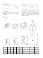
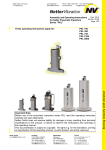
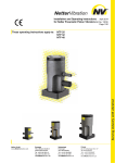
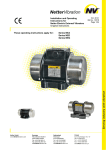
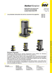
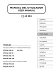
Feb. 2013
Assembly and Operating Instructions
BA
No.
1298E
for Netter Pneumatic Impactors
Page 1/24
Original Operating Instructions
These operating instructions apply to:
PKL 190
PKL 450
PKL 740
PKL 2100
PKL 5000
Contents
1 GENERAL NOTES
3 2 SAFETY
5 3 TECHNICAL DATA
7 4 DESIGN AND FUNCTIONING
9 5 TRANSPORT AND STORAGE
10 6 INSTALLATION
11 7 START-UP / OPERATION
19 8 MAINTENANCE / REPAIR
20 9 TROUBLESHOOTING
21 10 SPARE PARTS
21 11 ACCESSORIES
22 12 DISPOSAL
23 13 ENCLOSURES
24 Scope of delivery
The PKL are delivered with the following
components as standard:
• Pneumatic impactor (PKL)
• Operating instructions
• Packaging
Check the packaging for possible signs of
transport damage. In the event of damage
to the packaging, check that the contents
are complete and undamaged. If there is any
damage, inform the shipping agent. Compare the scope of the delivery with the delivery note.
For changes to the scope of delivery
please refer to the delivery note.
2
1 General Notes
Information on the operating instructions
Use and storage of the operating
instructions
Before use of the pneumatic impactors of
the series PKL read this operating manual
carefully. It is the basis for any action taken
with regard to the PKL and may be used
for training purposes. The operating
manual should subsequently be stored
near the PKL.
Limitation of liability
All technical information, data and
instructions on installation, operation and
maintenance in these operating instructions
are based on the latest information
available at the time of printing and take
into account our past experience to the best
of our knowledge.
No claims can be derived from the
information, illustrations and descriptions in
these operating instructions.
Target group
The target group of these operating
instructions is qualified technical personnel
from the mechanical engineering sector who
have a basic knowledge of pneumatics and
mechanics.
Installation, commissioning, maintenance,
fault elimination and disassembly of the
PKL must only be performed by persons
who have been instructed in the proper
handling of the units.
Persons who have not been instructed
accordingly must not carry out any works
on the PKL.
The manufacturer does not assume liability
for damages resulting from:
• failure to observe the operating
instructions
• improper use
• unauthorized repairs
• technical modifications
• use of inadmissible spare parts
Translations are made to the best
knowledge. kÉííÉêVibration does not
assume liability for translation errors, even
if the translation was made by us or on our
behalf. Only the original German version is
binding.
Copyright
This documentation is subject to copyright.
All rights e.g. for translation, photo-mechanical
reproduction, printing or reproduction (e.g.
data processing, data carriers and data
networks) of this operating manual, or parts
thereof,
are
strictly
reserved
to
kÉííÉêVibration.
3
The following instruction and warning symbols are used in these operating instructions.
DANGER
referring to a possible risk, which, if not avoided, can
result in death or serious injury.
CAUTION
referring to a possible risk, which, if not avoided, can
result in serious injury and/or equipment damage.
CAUTION:
LOOSE PARTS
referring to a possible risk, which, if not avoided, can
result in serious injury or equipment damage.
IMPORTANT
note with especially useful information and tips.
ENVIRONMENTALLY
refers to the obligation of an environmentally friendly
FRIENDLY
disposal
DISPOSAL
Information on the PKLs
Netter pneumatic impactors series PKL
comply with the EC machine directive
2006/42/EC.
Special features
• high impact force
• low air consumption
• reduced noise level due to elastomer
insert
In particular, standard DIN EN ISO 12100
has been observed.
4
2 Safety
Designated use:
Impactors are intended for assembly into
machinery where they are used to knock
off stubborn residues from walls, to
evacuate
residues
from
weighing
containers and to prevent bridging and
rat-holing, as long as the material remains
capable of flowing.
Any other use is considered improper use.
There are no built-in safety devices
CAUTION
Qualification of the personnel:
Assembly, commissioning, maintenance
and repair of the impactors must be
performed only by authorized qualified personnel.
Any handling of the pneumatic impactors
lies within the responsibility of the operator.
Accessories which ensure the correct
operation and safety must provide a
protection type required for the specific
use.
Netter GmbH does not assume liability for damage or injury resulting from
technical modifications to the product or failure to observe the
instructions and warnings in this operating manual.
Source of danger:
Faulty hose connections.
Possible consequences of non-observance
A pressurized hose coming loose can cause severe
injury.
CAUTION
Avoiding the danger:
The hose lines must be securely connected. This
must be checked at regular intervals and the screw
connections have to be retightened if necessary.
Source of danger:
PKL impactors work with compressed air.
Possible consequences of non-observance:
A pressurized hose coming loose can cause severe
injury.
CAUTION
Avoiding the danger:
Ensure that the compressed air is shut off from the
supply lines when working on the PKL.
Source of danger:
Pneumatic impactors are not mechanically closed on the impact side.
The impact piston and/or impact plate are loosely mounted.
Possible consequences of non-observance:
Falling parts can cause injury or material damage.
CAUTION
Avoiding the danger:
Ensure that the impact piston and/or impact plate remain in the housing during
installation and disassembly!
5
Source of danger:
Impactors, parts of the construction and air
connectors may become loose, due to
vibration.
Possible consequences of non-observance:
Falling parts can cause material damage or
injury.
DANGER
Avoiding the danger:
Screw retention devices and/or Loctite or
similar are to be used. Screwed connections
and air connectors should be checked after 1
hour of operation and then at regular intervals
(generally once per month) and tightened if
necessary.
Netter fastening sets NBS are recommended
for the attachment of impactors.
Pneumamatic impactors PKL 450 should be
installed with a dampening set; PKL 2100 and PKL
5000 must be mounted with a damper plate.
In critical installation situations it is required to
secure the vibrator with a clamp and steel rope.
Source of danger:
In the vicinity of the impactor, or structures
connected to the impactor, the noise level can
exceed 85 dB(A).
Possible consequences of non-observance:
Human hearing can be permanently damaged
by the high noise level.
CAUTION
Avoiding the danger:
When working in the noise area, ear
defenders are required if the sound level
exceeds 85 dB(A).
Preferably the PKL should be installed with
the EE kit.
6
3 Technical Data
tÉáÖÜí=çÑ= cçêÅÉ=çÑ=
éáëíçå=
áãé~ÅíG=
Type
PKL 190/4
PKL 190/6
PKL 450/4
PKL 450/6
PKL 740/3
PKL 740/4
PKL 740/5
PKL 740/6
PKL 2100/4
PKL 2100/5
PKL 5000/4
PKL 5000/6
xâÖz=
MINV=
MINV=
MIQQ=
MIQQ=
MITQ=
MITQ=
MITQ=
MITQ=
OINM=
OINM=
QIVS=
QIVS=
xâÖz=
MIQP=
MISM=
MIRS=
MIVO=
NIPM=
NIUM=
OINM=
OITM=
QIOM=
6,20=
SISM=
10,60=
Air consumption/
léíáãìã==
lîÉê~ää= pìáí~ÄäÉ=Ñçê=
impact
ï~ää=======
çéÉê~íáåÖ==
ïÉáÖÜí==
~í=çéíáãìã=éêÉëëìêÉ=
íÜáÅâåÉëë=çÑ=
éêÉëëìêÉ==
=
xÄ~êz=
xkçêã~ä=äáíÉêz=
xâÖz=
xããz=
QIM=
MIMV=
MIU=
N=Ó=O=
SIM=
MINQ=
MIU=
N=Ó=O=
QIM=
MINP=
NIS=
N=Ó=P=
SIM=
MINU=
NIS=
N=Ó=P=
PIM=
MIOT=
OIS=
O=Ó=Q=
QIM=
MIPU=
OIS=
O=Ó=Q=
RIM=
MIQP=
OIS=
O=Ó=Q=
SIM=
MIRQ=
OIS=
O=Ó=Q=
QIM=
NIRR=
6,7
P=Ó=R=
RIM=
NIVP=
6,9=
P=Ó=R=
QIM=
NIRM=
NSIM=
Q=Ó=U=
SIM=
OIOM=
NSIR=
S=Ó=NO=
*The impact force corresponds to the impact of the indicated weight falling from a height of 1m.
Admissible operating conditions
Drive medium
Clean (Filter ≤ 5 µm, quality class 3 according to DIN ISO 8573-1), lubricated
compressed air or lubricated nitrogen.
Lubrication
Fill mist lubricator with acid- and resin-free pneumatic oil,
ISO viscosity class according to DIN 51519, VG 5 to VG 15.
Recommendation: Klüber „AIRPRESS 15" for temperatures up to 60°C.
Operation in a dusty environment is possible.
In consultation with kÉííÉêVibration the PKL can also be operated without
lubrication.
IMPORTANT
Operating pressure
Operating pressures between 2.5 bar and 7.0 bar are possible.
The actual air pressure set on the regulator must not exceed the optimum
pressure by more than 1 bar (maximum pressure).
Frequency of impacts
A maximum of 10 impacts in a row at an impact frequency of 15 impacts/min and
180 impacts/h.
This impact sequence must not be exceeded.
Ambient temperature
-20°C to 60°C
HT version:
-20°C to160°C
The admissible ambient temperatures must not be exceeded or fallen short of
during operation.
*) Higher operating pressures and temperatures are only possible following consultation and written permission
from Netter GmbH application engineers.
7
Type designation
The type designation of PKL impactors
has the suffix /3, /4, /5 or /6. These
numbers are derived from the optimum
operating pressure, i.e. the PKL 740/4
works most effectively at a pressure of
4 bar.
Noise level
Preferably the PKL should be installed with
the EE kit. This reduces the impulse
(rubber hammer effect). With this kit the
noise level is around 75 dB(A) (individual
sound event).
Depending on the impact sequence the
continuous noise level is below this value.
The sound emitted by the PKL can be
dampened by a cover (upon request). This
only makes sense if the impacted sheet
metal is also dampened (e.g. by heat
insulation material).
Operating time
The technical performance data will
change in the course of the operating
time (wear).
Dimensions
PKL 190
PKL 450
^=
_=
xããz= xããz=
PU=
NNN=
PKL 190
TPIR=
NOS=
PKL 450
VM=
NQM=
mhi=TQM=
PKL 2100 ÕNOM= ÕNUM=
PKL 5000 ÕNNQIP= ÕNUM=
Type
`=
xããz=
NR=
NQ=
NR=
NT=
OO=
PKL 740
Õ=a=
xããz=
VIM
NPIM=
NPIM=
NPIM=
NTIM=
b=
xããz=
⎯=
⎯=
RM=
⎯=
⎯=
8
c=
=
d=NLUI=kt=S=×=N=
d=NLUI=kt=S=×=N=
d=NLUI=kt=S=×=N=
d=NLUI=kt=S=×=N=
d=NLUI=kt=S=×=N=
PKL 2100
PKL 5000
d=
xããz=
VMIM=
VMIM=
NMMIM=
ÕNRO=
ÕNRO=
e=
xããz=
NSPIR=
NVOIM=
OPUIR=
PMNIR=
PTSIR=
4 Design and Functioning
The pneumatic interval impactor is a
pneumatic “hammer”.
Compressed air P flows beneath the piston
C and pushes it against one or two springs
B.
Upon exhaust, the air chamber below the
piston is emptied all at once.
The piston C (hammer) is shot against an
elastomer (EE kit) or against an impact
plate E by the springs, and the plate
transfers the blow F.
If no Elastomer is used, the piston hits
directly against the mounting surface. In
the standard versions the impact plate is
always made of steel and can be replaced
by an Elastomer impact plate.
The air is evacuated via the silencer A.
The unit is attached via flange D by four
fastening screws. (PKL 190 and PKL 450
2 fastening screws).
Pneumatic impactors only work after
assembly, since the piston chamber is then
sealed by an o-ring installed in the contact
surface.
Special feature of PKL 740 (without
illustration)
A 3/2-way valve and a quick air-exhaust
valve are integrated in the valve head of
the PKL 740. The control valve existing on
customer’s site can therefore be mounted
at any distance from the PKL 740.
The pilot air supply must be connected
laterally. A silencer is mounted on the
exhaust outlet for the ventilation.
ST kit
The ST kit permits a continuous impact sequence with permanent compressed air
supply.
EE kit
The EE kit reduces the sound level and
creates a rubber hammer effect.
9
5 Transport and Storage
Check the packaging for possible signs of transport damage. In the event of
damage to the packaging, check that the contents are complete and
IMPORTANT undamaged. If there is any damage, inform the shipping agent. Compare the
scope of delivery with the delivery note.
The units are packed ready-to-install.
The type label is attached to the impactor.
Accessories and add-on parts are delivered
unmounted, unless otherwise agreed.
Special transport conditions are not
stipulated.
The units should be stored in a clean, dry
environment.
PKL 190, PKL 450 and PKL 740 must be
screwed or clamped to a plate before
operation. The impact plate must be
inserted. Use ear protections
The storage temperature should be
between -40 and +60°C. (This does not
apply to the operating temperature).
PKL impactors must be oiled before going
back into storage (pour machine oil into air
inlet port and activate briefly).
Packaging
The packaging protects the unit from
transport damages. The material of the
packaging has been selected based on
environmentally
and
disposal-friendly
aspects and can therefore be recycled.
Recycling the packaging reduces raw
material consumption and the waste
volume.
10
6 Installation
Ensure that the compressed air supply is shut
off during installation or when working on the
CAUTION impactor and air supply lines.
Pneumatic impactors PKL 190, PKL 450 and PKL 740 are open on the impact
side. Ensure that the impact piston remains in the housing during installation!
CAUTION
CAUTION
Impactors of the series PKL 2100 and PKL 5000 must always be installed
with impact plate and damper plate (included in the scope of delivery)!
PKL impactors are screwed to level reinforcement sections
or weld-on consoles (œ0.3mm flatness). Suitable weld-on
consoles (see illustration on the right) are available from
kÉííÉêVibration (see Accessories).
Weld-on plates must not be welded directly onto the
panels of the construction, since they are too stiff. Use
an intermediate layer of 1.5 times the sheet thickness
(example A). Particularly in the type of attachment shown
in A, the screws may break and are then difficult to
replace, in contrast to example B.
The fastening sets NBS serve to securely and permanently
fasten the PKL impactors.
kÉííÉêVibration supplies these fastening sets NBS
(screw, springs and matching washers) on request.
ST kit for PKL 740
The ST kit connects the control port with the piston
chamber. The impactor continues to strike as long as
compressed air is applied.
In this case only one air supply line is required.
See Assembly Instructions for ST kit.
Attention: For installations with automatic control ST, the
silencer must be screwed on to the air supply.
11
ST
ST kit for PKL 190 and PKL 450
In this case a 3/2-way valve with air supply
to P is required.
The ST kit connects the control port with the
piston chamber.
The impactor strikes as long as air is applied
to P. See Assembly Instructions for ST kit.
Circuit diagrams see chapter 6
“Installation”.
Example: PKL 450.
ST kit for PKL 2100 and PKL 5000
The ST control connects the control port
with the piston chamber and is integrated in
the PKL.
ST
ST kit for PKL 5000
In this case a control valve has to be
mounted onto the PKL. The control valve is
internally connected to the piston chamber.
The impactor then continues to strike as long
as compressed air is applied. See Assembly
Instructions for ST kit.
The impact sequence can be set by means
of a throttle (optionally).
Circuit diagrams see chapter. 6
"Installation”.
EE kit for PKL 190, PKL 450 and PKL 740
A spacer plate with a replaceable
elastomer and 0-ring is installed between
impactor and mounting surface. See
Assembly Instructions for EE kit.
Example: PKL 190.
e.g. EE kit for PKL 190
12
EE kit for PKL 2100 and PKL 5000
The piston hits against an impact plate. The
air channel is integrated in the housing. The
exhaust air escapes into the atmosphere via
the silencer.
A 3/2-way air valve is required if the control
valve at the customer’s site is mounted at a
distance of more than 15 m from the PKL.
If the impactor is fitted with the EE kit, the
steel impact plate with damper ring and
O-ring is replaced by an elastomer impact
plate with O-ring.
PKL 2100 and PKL 5000 must always be
installed with impact plate and damper
plate.
CAUTION
Impact plate Damper plate
Use lock nuts or a locking fluid, e.g. Loctite 270, in order to prevent loosening.
Also secure the compressed air supply lines with a suitable retention agent.
Use the tightening torques shown in the table below.
Higher tightening torques can lead to the fracturing of screws or tearing of
threads. Incorrect attachment of screws can lead to detachment of the device
due to vibration. This can result in personal injury and damage to material!
Recommended average tightening torques for screws property class 8.8 on PKL
housings (screws as delivered, with no additional lubrication)
Type
Thread/hole pattern mm)
Tightening torque
PKL 190
M 10 / 90
51 Nm
PKL 450
M 12 / 90
87 Nm
PKL 740
M 12 / 50 × 100
87 Nm
PKL 2100
M 12 / Õ152
87 Nm
PKL 5000
M 16 / Õ152
215 Nm
When using fastening sets (NBS series) with screw or elastomer springs, the
tightening torques are lower.
CAUTION Please observe the information and instructions supplied with these accessories.
PKL 190 and PKL 450 with NBS
The PKL 450 with ST kit is first attached to
the dampening set NBS 450, and then the
lower ST screws are mounted.
Example: PKL 450
ST
Dampening set NBS 450
13
Installation PKL
The maintenance unit should consist of filter, regulator and mist lubricator. (see
chapter. 3 „Technical Data, Drive medium “)
A cock valve 1 to shut off the main line and a
maintenance unit 2 are recommended for all
installations.
IMPORTAN
T
Connect the hoses of the PKL as shown on the pneumatic circuit diagrams!
Installations for PKL 190, PKL 450, PKL 2100 and PKL 5000
Standard installation:
A 3/2-way valve 3 must be used for the
control.
Upon switching of the valve the piston
chamber is ventilated and exhausted and
the impactor is striking.
The impact sequence can be determined
by a Netter electronic timer AP 4. Electric
or pneumatic controls are available on
request.
The 3/2-way valve 3 can be installed at
greater distances (up to 15 m) from the
impactor.
Examples: PKL 450 and PKL 2100.
Installation with long supply line:
If the supply line A exceeds 15 m, an
additional 3/2-way valve 9 and a throttle 6
must be installed.
Line B must have a minimum length of
1 m and during commissioning the
throttle 6 must be adjusted so as to
switch the 3/2-way valve 9 with time
delay.
B
For this purpose the kÉííÉê start control
can be installed (available on request)
which includes all necessary components.
Example: PKL 190.
14
A
Installation of several PKLs:
It is possible to operate several impactors
in parallel with just one control and one valve.
The length of the connecting lines from valve
to the PKL must not exceed 1 m, otherwise
the control piston or membrane in the unit will
move too slowly and not reach the sealing
final position.
The 3/2-way valve 3 can be installed at
greater distances from the impactor if
additional 3/2-way valves 9 are used.
If several PKLs are operated, the overall
length of the air supply line must not
exceed 50 m.
Example: PKL 450.
Installation with ST kit:
With an ST kit the PKL continues to strike
as long as pressure is applied.
The PKL can then achieve an impact
frequency of approx. one impact/second.
This maximum impact sequence must be
reduced to the max. permissible impact
sequence (e.g. using a throttle valve 6
installed in the air supply line).
With an ST kit a PKL can be operated with a
2-, 3-, or 4-way valve 3, even if it is located
at a greater distance (up to 50 m).
The length of the connecting lines from
valve to PKL must not exceed 1 m,
otherwise the control piston or the
membrane in the unit will move too slowly
and not reach the sealing final position.
Examples: PKL 450 and PKL 2100.
15
Installation with coupling to other
functions:
If the PKL 740 is fitted with an ST kit, it
can be coupled to another function without
having to use a control or pulse generator.
The adjoining illustration shows the
coupling to an opening cylinder 8 on a
weighing container. The impactor is not
activated. Once the flap is opened, the
impactor will strike at the frequency set by
the throttle as long as the flap remains
open.
Example: PKL 2100.
Installations for PKL 740
Standard installation:
The PKL 740 is the only PKL with
integrated 3/2-way pneumatic valve in the
valve head.
Upon switching of the valve the piston
chamber is ventilated and exhausted and
the impactor is striking.
The impact sequence can be determined
by a Netter electronic timer AP 4. Electric
and pneumatic controls are available on
request.
The main air supply is constantly applied to
the valve head. The control line from the
activation valve existing on customer’s site
3 and the impactor can be very long (e.g. 50
m). In case of long supply and control lines
the charge time of the impactor can take
several seconds. If the compressed air lines
are long (e.g. 50 m), a pause and duty time
of at least 5 seconds should be set on the
electronic timer AP 4. If shorter lines are
used, these times can be reduced
accordingly, e.g. to 2-3 seconds.
16
Installation of several PKL 740:
Parallel operation of several PKL 740 is
possible with just one control and one
valve.
In this case the overall length of the air
supply line must not exceed 50 m.
Installation with ST kit:
With an ST kit 7 the PKL continues to
strike as long as pressure is applied.
The PKL can then achieve an impact
frequency of several impacts/second. This
maximum impact sequence must be
reduced to the max. permissible impact
sequence (e.g. using a throttle valve 6
installed in the air supply line)..
A PKL with ST-control 7 can be activated
using a 2-, 3- or 4-way valve 5, even if it is
mounted at a greater distance (possible
up to 50m).
If a Netter electronic timer (AP) 4 is used,
the PKL strikes several times during the
duty time.
Installation with coupling to other
functions:
If the PKL 740 is fitted with an ST kit, it
can be coupled to other functions, without
having to use a control or pulse generator.
The adjoining illustration shows the
coupling to an opening cylinder 8 on a
weighing container. The impactor is not
activated. Once the flap is opened, the
impactor will strike at the frequency set by
the throttle as long as the flap remains
open.
17
Recommended cross-sections for valves and hoses
PKL 190, PKL 450, PKL 740, PKL 2100 and PKL 5000:
Control lines, control valves:
NW 6 × 1
Main air supply:
NW 6 × 1
Use NW 6 for connection of the control valve to PKL and do not exceed a
length of 15 m.
For simultaneous activation of several PKLs greater cross sections have to
IMPORTANT be used for the main air supply line.
For the activation of several PKL the total length of the compressed air supply
lines must not exceed 50 m.
Check list for installation:
.
1) Consider expected operating temperature.
2) Install main cock and maintenance unit (filter, regulator, as required), valve and supply line.
3) Mount weld-on console (if necessary).
4) Install with fastening set (NBS).
5) Install PKL 2100 and PKL 5000 with damper plate.
6) Secure fastening screws with glue (e. g. Loctite).
7) Glue in air supply lines!
8) Observe information on hose length and nominal width.
9) Secure the unit against falling down!
18
7 Start-up / Operation
Lubricated
compressed
air
recommended for PKL impactors:
is
Fill mist lubricator with acid and resin free
pneumatic oil, ISO viscosity class
IMPORTANT according to DIN 51519, VG 5 to VG 15.
Recommendation: Klüber “AIRPRESS 15”
for temperatures up to 60°C.
When selecting the lubricator, bear in mind
that the air consumption of the PKL is very
low. The selection of the lubricator is
dependent on the number of impactors to be
operated at the same time.
Units with 1/8” and 1/4” connectors are
recommended. Larger units may not
respond.
Set to the lowest number of drops.
ATTENTION:
Adjust the number of drops with the unit running.
IMPORTA Only after the mist lubricator has been adjusted and is functioning
NT
correctly, the device is ready for operation.
Impact frequency
Max.10 impacts in succession at an impact frequency of
15 impacts/min and 180 impacts/h.
CAUTION This impact sequence must not be exceeded.
Regulation of Impact Frequency:
PKL must be used for clocked operation
only!
with ST control:
In a PKL with ST control the impact
frequency can be regulated by means of
the throttle.
without ST control:
The impact frequency must be regulated
using an external control, e.g. with a
3/2-way valve and a Netter electronic timer
AP
Regulation of Impact Strength:
The impact strength can be reduced by
lowering the pressure (exception ST kit).
Throttling the air supply (via a throttle, cutoff valve, etc.) will not reduce the impact
strength, but will delay the charge time.
Check list for start-up:
1) Check hose connections before opening the compressed air supply.
2) If required, set the desired impact force on the pressure regulator (does not
apply if ST kit is installed).
3) If the ST kit is installed, the frequency can be regulated using a throttle. Do not
set faster than necessary (service life, noise pollution).
4) Adjust mist lubricator if existing.
5) After 1 hour of operation the compressed air lines, attachment and fastening
screws should be checked and tightened if necessary. After this, the
attachment and fastening screws and compressed air lines should be checked
CAUTION
at regular intervals (generally once per month) and tightened if necessary.
19
8 Maintenance / Repair
Before starting inspection or service work,
shut off the compressed air supply and
CAUTION protect it against unintentional activation!
The drive medium must be clean (filter
≤ 5 µm, class 3).
Unfiltered compressed air leads to high
IMPORTANT wear, blocked silencers or complete
break-down of the impactor.
The maintenance intervals will be shorter.
Maintenance schedule
Maintenance must be performed on a monthly basis.
Screw connections
Check total number
of impacts
Air supply lines
DANGER
Silencer
Check impacts
Mist lubricator
Filter of the maintenance unit
Screw connections should be checked and - if
necessary – tightened and secured with Loctite after
one hour of operation (after first commissioning)
and then at regular intervals.
After a maximum of 500.000 impacts a comprehensive
service should be carried out during which all seals and
guide rings should be replaced
Check for kinks and ensure that the lines are free from
obstructions. If necessary, clean the hoses and remove
kinks.
Clean and check function.
Check function.
Make sure that mist lubricator works correctly (contents
decreasing? Number of drops/h?). Refill oil.
Empty filter if necessary, clean (wash out) filter insert or
replace filter insert.
The maintenance intervals largely depend on the operating period and the
cleanness of the drive medium. Especially in units driven by oil-free and / or
dried compressed air, increased friction can create deposits which will slow
down the function.
If this is noticed (performance loss or even standstill), the impactors should be
cleaned and the sealing and guide rings replaced, if necessary. The
maintenance intervals are reduced.
IMPORTANT
Cleaning the impactor:
When cleaning the impactor, it is necessary to remove and clean the piston. In
case of wear, the guide rings and piston seals must be replaced. A special tool is
necessary (available upon request) to insert the piston. Alternatively, maintenance,
repair and comprehensive servicing can be carried out by kÉííÉêsáÄê~íáçåK
20
9 Troubleshooting
Fault
No
function
Possible causes
Mounting surface not
plane.
Malfunction of valve
and control.
Troubleshooting
Pressure loss via
O-ring.
Check impactor
without valve and
control
Check pressure.
Check valve switching.
Check seals of
knocking and control
pistons (PKL 190).
Remedy
Ensure mounting surface
with flatness error ± 0,1 mm!
Check 3/2-way valve and
control, replace if
necessary.
Adjust operating pressure.
Replace valve if necessary.
Replace seals on the
knocking and control
pistons.
General wear
Housing, membrane
and control piston
worn?
Replace affected parts and
seals.
PKL not mounted
correctly.
Check fastening
screws.
Tighten fastening screws or
replace if necessary.
Air supply
No
function Seals are worn.
with
leakage
from top
No function
with leakage
on the mounting surface
Mounting surface not Check mounting
even.
surface.
Check O-ring.
No function
with ST kit.
Weak impact
Operating pressure
too low.
Air supply
Control valve soiled
Silencer soiled
Wear, leakage
Ensure mounting surface
with flatness error ± 0,1 mm!
Insert O-ring into the groove
and replace it if damaged.
Check
unit
type. Increase pressure.
Check pressure.
Check pressure
Adjust pressure.
Check control valve. Clean control valve or
replace if necessary.
Check silencer.
Clean silencer.
Replace the seals.
10 Spare Parts
When ordering parts, please supply the following details:
1. Required quantity
2. Description and position of the spare part
3. Type of unit
21
11 Accessories
The following accessories are available for the pneumatic impactor PKL (upon request):
Description
Remarks
NBS 190 for PKL 190
NBS 450 for PKL 450
NBS 1, 2 and 5 for PKL 740
NBS 2100 for PKL 2100
Fastening sets NBS
NBS 5000 for PKL 5000
Screws, springs and matching lock washers for secure
fastening.
When using this type of control, the pauses between the
ST kit
individual impactor sequences must be long enough
(see chapter 6).
For compressed air supply (working air, pilot air), in various
Hose material and fittings
qualities and dimensions.
Way valves
Electrical, pneumatic, manual
Throttle valves
For cycle control on PKL with ST kit.
Maintenance units
Filter, regulator with pressure gauge, mist lubricator.
Netter electronic timers
Electrical (also for special voltages) or pneumatic controls.
For round and rectangular containers, also for use on insulated
Weld-on consoles
containers, funnels etc.
Vacuum fixing devices,
For quick relocation on containers etc.
quick clamping devices
Noise reduction
Hoods, covers, EE kit.
Safety suspension
Clamp with steel rope and snap hooks.
kÉííÉê start control
For long supply lines (>15m).
Flanges with different dimensions available at extra cost,
Special versions:
high-temperature versions and further information on request.
22
12 Disposal
The parts are to be correctly disposed of, depending on the material.
Material specifications:
PKL 190
PKL 450
PKL 740
piston, springs
piston,
springs
piston,
springs
Aluminium
housing,
pilot piston
housing,
pilot piston
housing
PTFE, PU,
VITON, NBR
Spring guide,
ring stop,
seals
cover,
seals
cover,
seals,
membranes
PKL 2100
Stainless
steel
Steel
impact plate,
impact piston,
springs,
ST- tube
inner tube,
outer tube,
reducer,
top cover, flange,
ST-Ring, ST-plate
seals,
dampening rings,
dampening plates,
impact plate -EE
Valves: Brass, nickel-plated; Plastic
All units can be disposed of through Netter GmbH.
The applicable disposal prices are available upon request.
23
PKL 5000
Reducer,
ST tube, ST plate,
ST connecting angle
outer tube, inner tube,
impact plate,
top cover, flange,
impact piston, springs
seals,
dampening rings,
dampening plates,
impact plate -EE
13 Enclosures
Enclosure(s):
Declaration of incorporation
Additional information available upon
request:
IMPORTANT Leaflet No. 27 (PKL), and others.
24