1
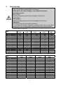
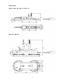
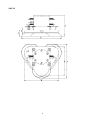
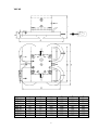
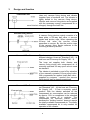
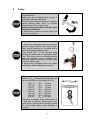
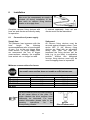
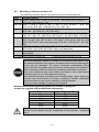
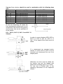
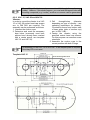
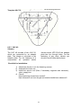
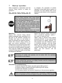
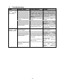
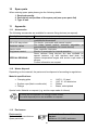
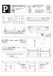
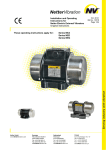
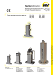
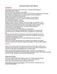
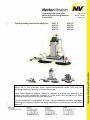
Operating instructions for
Netter Vacuum-Fixing-Devices
Series VAC
These operating instructions apply for:
VAC 8
VAC 10
VAC 11
VAC 12
Feb. 2012
BA Nr. 1250E
Page 1/20
VAC 15
VAC 20
VAC 30
VAC 40
Important note:
Before use of the pneumatic linear vacuum-fixing-devices series VAC read this
operating instruction carefully and store afterwards.
Netter GmbH does not assume liability for damage to property and persons if the
product has been technically modified or if the notes and regulations of these
operating instructions have not been observed.
This documentation is copyrighted. All rights, e.g. for translation into other languages,
reprinting and copying of these operating instructions or parts hereof remain strictly
reserved.
Table of Contents
1
GENERAL NOTES
3
2
TECHNICAL DATA
4
3
DESIGN AND FUNCTION
8
4
SAFETY
9
5
TRANSPORT AND STORAGE
11
6
INSTALLATION
12
6.1
Connection of power supply
12
6.2 Mounting of vibrator and hose set
6.2.1 VAC 8, VAC 10, VAC 11 and VAC 12
6.2.2 VAC 15, VAC 20 and VAC 30
6.2.3 VAC 40
13
14
15
16
7
START-UP / OPERATION
17
8
SERVICE, MAINTENANCE
18
9
TROUBLESHOOTING
19
10
SPARE PARTS
20
11
APPENDIX
20
11.1
Accessories
20
11.2
Waste disposal
20
11.3
Enclosures
20
Scope of delivery:
Check the packing for possible shipping damage.
If the packing is damaged check the contents for completeness and
possible damage. In case of damage inform the transport agent.
Compare the scope of supply with the delivery note.
2
1
General notes
Netter vacuum fixing devices of series
VAC for pneumatic vibrators are in
strict compliance with the EC Machine
Directive 2006/42/EC. The standard
DIN EN 12100 has been observed in
particular.
Vacuum fixing devices of series VAC
are used for quick fastening of
vibrators to smooth and, to a limited
extent, also to rough and curved
surfaces.
They are used in combination with
vibrators for the emptying of transport
containers or drums, for the cleaning
of pipes etc.
Vacuum fixing devices are used where
conventional fastening methods
for vibrators fail, frequent relocation of
vibrators is required and welding or
bolting is not possible.
The drive medium is compressed air
or nitrogen.
Applications in the food industry and in
wet areas are possible under strict
compliance with the corresponding
operating instructions of the operating
company and if the attached vibrator
is also suitable for such applications.
These vacuum fixing devices can also
be used outdoors, but not in or under
water or any other fluids.
In these operating instructions the following information and danger symbols are used.
Notes on important processes
Warning of a danger source
Important note on processes to
be especially observed
Environmental waste disposal
3
2
Technical data
Drive medium:
Clean (≤ 5 µm filter) compressed air or nitrogen
Unfiltered air will cause damage to the mounted vibrators.
Operating pressure:
4 bar to 6 bar*
Operating pressures must not be exceeded or fall short of
Temperature:
-10°C to 60°C*
Operating temperatures must not be exceeded or fall short of.
Lubrication:
VAC fixing devices do not require lubrication.
For the mounted vibrator lubricated compressed air may be specified.
Please refer to the corresponding operating instructions for the vibrator.
*) Higher operating pressures and temperatures are only permitted after consultation and written confirmation by
application engineers of Netter GmbH.
Type
VAC 8 + HG 10 N
VAC 8 + HG 10 S
VAC 10 + HG 10 N
VAC 10 + HG 10 S
VAC 11 + HG 10 N
VAC 11 + HG 10 S
VAC 12 + HG 10 N
VAC 12 + HG 10 S
VAC 15 + HG 15 N
VAC 15 + HG 15 S
VAC 20 + HG 15 N
VAC 20 + HG 15 S
VAC 30 + HG 30 N
VAC 30 + HG 30 S
VAC 40 + HG 40 N
Generated vacuum [bar]
4 bar
6 bar
0,60
0,85
0,60
0,85
0,60
0,85
0,60
0,85
0,60
0,85
0,60
0,85
0,60
0,85
0,60
0,85
0,60
0,85
0,60
0,85
0,60
0,85
0,60
0,85
0,60
0,85
0,60
0,85
0,60
0,85
Generated suction power* [N]
4 bar
6 bar
340
481
340
481
465
658
465
658
710
1005
710
1005
1.250
1.770
1.250
1.770
1.476
2.091
1.476
2.091
2.724
3.859
2.724
3.859
4.086
5.789
4.086
5.789
5.448
7.718
Weight
[kg]
0,95
1,20
1,05
1,30
1,25
1,50
2,85
3,20
3,40
3,75
7,25
7,60
11,50
12,00
20,00
* Maximum suction power at 5 bar. For operation of a vibrator a higher pressure may be required.
Type
VAC 8 + HG 10 N
VAC 8 + HG 10 S
VAC 10 + HG 10 N
VAC 10 + HG 10 S
VAC 11 + HG 10 N
VAC 11 + HG 10 S
VAC 12 + HG 10 N
VAC 12 + HG 10 S
VAC 15 + HG 15 N
VAC 15 + HG 15 S
VAC 20 + HG 15 N
VAC 20 + HG 15 S
VAC 30 + HG 30 N
VAC 30 + HG 30 S
VAC 40 + HG 40 N
•
Air consumption [l/min]
4 bar
6 bar
40
60
20
22
40
60
20
22
40
60
20
22
60
122
29
36
110
170
41
52
110
170
41
52
110
170
49
60
220
340
Noise level * [dB(A)]
4 bar
6 bar
72
72
72
72
72
72
72
72
74
74
74
74
74
74
74
74
74
74
74
74
74
74
74
74
74
74
74
74
74
74
The noise level was measured at a distance of 1 m without vibrator. The noise level of vibrators is in most cases higher.
4
Dimensions:
VAC 8 / VAC 10 / VAC 11 / VAC 12
VAC 15 / VAC 20
5
VAC 30
6
VAC 40
Typ
VAC 8
VAC 10
VAC 11
VAC 12
VAC 15
VAC 20
VAC 30
VAC 40
A
19
22
20
25
50
70
70
90
B
8
8
5,5
10
25
30
30
55
C
150
200
300
300
350
440
428
440
All dimensions in [mm] - measurement X depending on vibrator
7
D
127
175
276
268
290
370
370
370
E
30
26,5
26
68
100
150
340
375
F
55
55
55
100
150
200
400
425
3
Design and function
Functional unit
Hose set, vacuum fixing device and vibrator
together form a functional unit. The vibrator is
tightly bolted to the vacuum fixing device.
Vibrator and vacuum fixing device are supplied
with the necessary energy (compressed air or
nitrogen) through the hose set.
Vacuum fixing device
A vacuum fixing devices mainly consists of a
base plate, a 2/2-way ball valve, a vacuum
nozzle and suction cups. When operating the
2/2-way ball valve the vacuum nozzle
generates a vacuum. By this the suction cups
of the vacuum fixing device adheres to the
mounting surface by suction.
Hose set HG .. N
The hose set is normally available in two
different designs: Hose set "Standard" HG .. N
and hose set "Economy Air Supply" HG .. S.
The hose set supplies both vibrator and
vacuum fixing device with compressed air. A
manually operated 3/2-way spool valve is used
as standard.
The vibrator is switched on and off by actuation
of the manually operated 3/2-way spool valve.
With compressed air applied (main ball valve supplied by customer - opened) the vacuum
fixing device itself is always pressurized.
Hose set HG .. S
In addition to the standard function (see hose
set "Standard" HG .. N) the hose set „Economy
Air Supply“ HG .. S has a economy switch
position. With the vibrator switched off the
compressed air consumption can be reduced
by approx. 30% in comparison to the standard
version by means of a restrictor. This
compressed air reduction makes sense,
because the "holding function" does not require
the totally available compressed air. The totally
available compressed air is only needed for
operation of the vibrator.
8
4
Safety
Vacuum
fixing
devices
work
with
compressed air.
Make sure the compressed air supply is
switched off during installation.
Disconnect the supply lines (quick coupling)
before starting other work on holders,
vibrators and on the supply lines.
Before starting operation all hoses must
be tightly connected.
A hose under pressure coming loose can
cause severe injury.
In case of an unexpected pressure drop the
vacuum fixing devices may come loose.
They should therefore be secured with a
steel rope against dropping down.
From series VAC 11 the vacuum fixing
devices are fitted with an adjustable safety
rope. This rope must be pre-tensioned as
short as possible using a bulldog grip.
Should a holder come loose it should never
drop into a slack rope.
A fixing device dropping down can cause
bodily injury and/or damage to property.
When observing the minimum crosssections (Dmin), vacuum fixing devices can
also be mounted to round parts (Ø = D):
VAC 8:
Dmin: 110 mm
VAC 10:
Dmin: 110 mm
VAC 11:
Dmin: 110 mm
VAC 12:
Dmin: 350 mm
VAC 15:
Dmin: 650 mm
VAC 20:
Dmin: 850 mm
VAC 30:
Dmin: 1.500 mm
VAC 40:
Dmin: 1.500 mm
With parts of smaller cross section there is
a risk that a vacuum fixing device may
come loose. A fixing device dropping down
can cause bodily injury and/or damage to
property.
9
Vibrators bolted to vacuum fixing devices
may come loose by the effect of vibration.
Falling parts can cause damage to persons
and material.
Screw retention components and/or Loctite
or similar must be used. Screw connections
must be checked and, if necessary,
retightened after 1 hour of operation and
then at regular intervals (normally every
month).
Jan. / Feb. / ...
Not every pneumatic vibrator is suitable to the vacuum fixing device.
Applicable vibrators are listed in chapter 6.2 „Mounting of vibrator and
hose set“.
When choosing a different vibrator a preceding consultation is required.
Technical changes to the equipment may effect the characteristics
of these vacuum fixing devices or even damage the units and cause
the rejection of any warranty claims.
Permissible operating conditions:
Operating pressure:
4 bar to 6 bar*
Operating pressures must not be exceeded or fall short of
Temperature:
-10°C to 60°C*
Operating temperatures must not be exceeded or fall short of.
Lubrication:
VAC fixing devices do not require lubrication.
For the mounted vibrator lubricated compressed air may be specified.
Please refer to the corresponding operating instructions for the vibrator.
*) Higher operating pressures and temperatures are only permitted after consultation and written confirmation by
application engineers of Netter GmbH.
10
5
Transport and storage
Check the packing for possible shipping damage.
If the packing is damaged check the contents for completeness and
possible damage. In case of damage inform the transport agent.
Compare the scope of supply with the delivery note.
The vacuum fixing devices are packed
ready for installation. The type
designation is engraved on the base
plate (exceptions: VAC 8, VAC 10,
VAC 11 and VAC 12).
The units should be stored in boxes
and in a dry and clean environment.
When returning vacuum fixing devices
to the stores you should squirt some
drops of oil into the air inlet. On
complete units (hose set, vacuum
holder and vibrator) the machine oil
may also be squirted into the air inlet
side of the hose set. The entire unit
must subsequently be operated for a
short moment.
When ordering a vacuum fixing device
in connection with hose set and
vibrator, these components will be
completely
assembled,
unless
specified differently. Special transport
conditions are not specified.
The storage temperature may be between
-20°C and +80°C.
(This does not apply for operating temperature,
compare with chapter 4 Safety, “Permissible
Operating Conditions”).
11
6
Installation
Make sure the compressed air supply is
switched off during installation or any
other work on vacuum fixing devices,
vibrator or air supply lines.
Complete vacuum fixing devices with
hose set and vibrator are directly ready
for operation.
6.1
If ordered separately, hose set and
vibrator must first be assembled.
Connection of power supply
Supply line:
The pressure loss increases with the
hose
length.
The
following
recommendations refer to hose lengths
of max. 3 m to the next bigger hose
cross section. For longer supply lines
we recommend the use of bigger
cross-sections, whereby the supplied
hose socket can no longer be used.
Safeguard:
All vacuum fixing devices must be
secured against dropping down. From
series VAC 11 the vacuum fixing
devices are fitted with an adjustable
safety rope. With this rope pretensioned the fixing devices can be
held (e.g. to eye bolts) in application
position. Without this safeguard
vacuum fixing devices must only be
used if dropping down is impossible.
Minimum cross-sections for hoses:
A too small cross-section does not enable a sufficient vacuum.
Type
HG 10 N / S
HG 15 N / S
HG 30 N / S
HG 40 N
Hose socket
1/4“
3/8“
1/2“
1/2“
The drive medium must be clean (filtered).
Dirt will cause failure of the units. For
certain vibrators the drive medium must
additionally be lubricated. For more
detailed information please refer to the
operating
instructions
for
the
corresponding vibrator.
12
Hose size
NW 6
NW 9
NW 12
NW 12
≤ 5 µm
filter recommended
6.2
Mounting of vibrator and hose set
The following vibrators can be mounted to the vacuum fixing devices:
Type
Suitable vibrators
VAC 8 NCB 1, NCB 2, NCT 1, NCT 2, NTK 8 AL – NTK 18 AL, NTP 25 B+C**,
NTS 120 - NTS 180 HF + NF*
VAC 10 NCB 1, NCB 2, NCR 3, NCT 3, NCT 4, NTP 25 B+C**, NTK 15x,
NTK 18 AL, NTS 180 - NTS 250 HF + NF*, PKL 190
VAC 11 NCB 3, NCB 5, NCR 10, NCT 5, NCT 10, NTK 18 AL,
NTS 180 – NTS 250 HF + NF, PKL 450**
VAC 12 NCB 10, NCB 20, NCR 22, NCT 15, NCT 29, NTP 32 B+C**, PKL 450**,
PKL 740**, PKL 170*, NTK 25 AL, NTS 350 HF + NF, NTS 100/01, NTS 50/01
VAC 15 NCB 10, NCB 20, NCB 50, NCB 70, NCR 22, NCR 57, NCT 15, NCT 29,
NCT 55, NCT 108, NTP 32 B+C, NTP 48+C*, NTK 18 AL, NTK 25, NTS
75/01, NTS 70/02* with round base plate, NTS 250 - NTS 350 HF + NF, PKL
740
VAC 20 NCR 57, NCT 55, NCT 108, NTP 32 B+C, NTP 48 B+C, NTS 50/04*,
NTS 54/02, NTS 70/02, NTS 70/02 with round base plate
VAC 30 NCR 120, NCT 250, NTS 50/08*, NTS 50/04, PKL 2100, NVG 49/55/61,
NVG 82/84*
VAC 40 NTS 50/08*, NTS 50/10*
* consultation required, depending on individual case.
** Adapter plate required, please add to your order.
Not every pneumatic vibrator is suitable to the vacuum fixing device. With
drill patterns different to the ones for the above listed units the internal pilot
bores may be damaged. The above mentioned combinations (fixing
device/vibrator) have been tested and can be used without any limitations.
When choosing a different vibrator a preceding consultation is required.
Use screw retentions and nuts to fasten the vibrator. Use a liquid screw
retention agent (e.g. Loctite) against loosening.
Use tightening torques according to the following table. Higher tightening
torques may cause fracture of screws or tearing of threads. Inadequate
screw connections may cause loosening of units by vibration.
This can cause damage to persons and material!
Recommended mean tightening torques for screws of quality 8.8
(screws as supplied, without additional lubrication):
Thread
M6
M8
M 10
M 12
M 16
M 20
Tightening torque [Nm]
10,4
25,0
51,0
87,0
215,0
430,0
Vibrators must be cautiously and properly fastened. The fastening
screws for the vibrator must be retightened or checked after 1 operating
hour.
13
Vacuum fixing devices should be used in combination with the following hose
sets:
Type
Hose set (except PKL)
Hose set for PKL
VAC 8
HG 10 N or HG 10 S
VAC 10
HG 10 N or HG 10 S
VAC 11
HG 10 N or HG 10 S
HG 10 N or HG 10 S
VAC 12
HG 15 N or HG 15 S
HG 10 N or HG 10 S
VAC 15
HG 15 N or HG 15 S
HG 10 N or HG 10 S
VAC 20
HG 15 N or HG 15 S
HG 10 N or HG 10 S
VAC 30
HG 30 N or HG 30 S
HG 10 N or HG 10 S
VAC 40
HG 40 N
Of the two branching off hoses the
hose permanently pressurized is to be
connected to the vacuum fixing device
and the hose that can be switched off
to the vibrator.
6.2.1 VAC 8, VAC 10, VAC 11 and VAC 12
Vibrator:
In order to mount vibrators NCB, NCR or
NCT to a VAC 8, VAC 10, VAC 11 or
VAC 12 two tapped blind holes must be
drilled.
If a compressed air operated piston
vibrator of series NTS or NTK is to be
mounted, we recommend the use of an
adapter plate.
Otherwise one hole must be drilled into
the suction cup and the tapped hole
sealed with a sealing agent (e.g. Loctite).
For the size of thread refer to the
operating instructions for the respective
vibrator.
14
When drilling blind holes make sure not to drill through the suction cup
(rubber). However, if this should happen, you must seal the tapped holes with
a sealing compound (e.g. Loctite), as other no vacuum can be generated.
6.2.2 VAC 15, VAC 20 and VAC 30
Vibrator:
In order to mount the vibrator to a VAC
15 or VAC 20 socket head cap screws
acc. to DIN 7991 are required. The
assembly can be performed as follows:
1. Unscrew the suction cups.
2. Determine and mark the necessary
bore holes (commonly used bore
pitches have already been marked
with a centre punch, see template
VAC 15 and VAC 20).
3. Drill
through-holes
(diameter
depending on type of vibrator - see
operating instructions for vibrator).
Countersink bores from bottom side
of base plate (side of suction cup)
acc. to DIN 74-Bf....
4. Fasten the vibrator using the
specified socket head cap screws.
For this purpose use common screw
retentions.
5. Assemble the suction cups in the
correct position with both O-rings.
For assembly of the PKL 740 to the VAC 15 an adapter plate is required,
if the inlay EE is not used.
Template VAC 15
Do not drill through this aerea!
Template VAC 20
15
Do not drill through this aerea!
Template VAC 30
6.2.3 VAC 40
Vibrator:
The VAC 40 consists of two VAC 20,
which are connected by an adapter
plate. The vibrator is mounted to the
adapter plate. For the fastening of a
compressed air operated piston
vibrator series NTS 50/10 the adapter
plate has four through holes. For the
fastening of any other vibrator you
should consult Netter beforehand.
Checklist for installation:
1) Attach the vibrator. Lock the fastening screws.
2) Assemble the hose set.
3) Install the service unit (filter, if necessary regulator and lubricator),
valve, supply line.
4) Check!
Have fastening screws been locked?
Has information on hose length and nominal width been observed?
16
7
Start-up / operation
After completion of assembly work the
vacuum fixing device is ready for
operation.
or nitrogen. For operation of certain
vibrators a lubricated drive medium is
specified. For more details refer to the
operating instructions for the respective
vibrator.
The vacuum fixing device can be
operated with filtered compressed air
In case of an unexpected pressure drop the
vacuum fixing devices may come loose.
They should therefore be secured with a
steel rope against dropping down.
From series VAC 11 the vacuum fixing
devices are fitted with an adjustable safety
rope. This rope must be pre-tensioned as
short as possible using a cable clamp.
Should a fixing device come loose it should
never drop into a slack rope.
A fixing device dropping down can cause
bodily injury and/or damage to property.
Adjust the desired vibrator frequency
with a pressure regulator (option e.g. part of a service unit).
When using a vacuum fixing device
with hose set HG .. S you may activate
the Economy Air Supply function. For
this purpose turn the restrictor screw
in clockwise direction, until the fixing
device can be easily moved by hand.
Then start the vibrator by actuating the
manual 3/2-way spool valve on the
hose, the full vacuum will be
generated.
Handling:
Secure the vacuum fixing device
against dropping down and attach it to
the part to be vibrated. Operate the
2/2-way ball valve on the holder in
order to generate the required vacuum.
Check the vacuum fixing device for
tight and secure attachment. If the
fixing device can be loosened by hand,
you should increase the pressure (e.g.
on service unit with pressure regulator).
Then start the vibrator by actuating the
manual 3/2-way spool valve on the hose
and adjust the lubricator.
Adjust the lubricator while the vibrator is running. Exact details
concerning oil quality and quantity can be taken from the operating
instructions for the vibrator.
When relocating the vacuum fixing device with hose set HG .. S to
another surface the economy air supply function must be readjusted or
checked on the restrictor screw.
Checklist for commissioning:
1) Check! Has the VAC been secured against falling down?
2) Check all hose connections before opening the air supply.
3) Adjust the lubricator, if present.
4) If necessary adjust the required frequency on the pressure regulator.
Screw connections must be checked and, if necessary, retightened after
1 hour of operation and then at regular intervals (normally every month).
17
8
Service, maintenance
Before starting inspection and service work
shut off the compressed air supply and
secure it against unintended activation!
Check the fastening of vibrator and air supply connection at regular
intervals - normally every month. The service intervals for other
components are partly shorter, they may vary extremely, in dependence
on vibrator and environmental conditions.
Lubricator:
Suction cups:
With a lubricator connected in series
make sure that the lubricator works as
specified
(contents
diminishing?
number of drops/min? top up oil if
necessary).
The
suction
cups
must
be
permanently checked for wear and
need to be replaced if necessary.
Securing rope:
If the safety rope has been extremely
loaded by the vacuum fixing device
dropping down, it should be replaced
by a new one.
Cleaning:
Vacuum fixing devices may be
cleaned from outside with pressurized
water. After clean run the unit for a
short moment.
Silencer:
Vacuum nozzle:
Clogged silencers adversely affect the
power of vacuum fixing devices and
vibrators. In extreme cases it may
even lead to failure of the units.
Silencers should therefore be serviced
at regular intervals and washed out
with petroleum ether, if required. The
maintenance intervals mainly depend
on the purity of your drive medium and
the environmental conditions.
The vacuum nozzle may be clogged
by contaminated drive air. In this case
the nozzle must be disassembled and
cleaned in petroleum ether.
On VAC 8, VAC 10, VAC 11 and VAC
12 the externally arranged vacuum
nozzle is easy to disassemble and
clean.
Disassembly and cleaning of vacuum
nozzles on VAC 15, VAC 20, VAC 30
and VAC 40 should only be performed
by kÉííÉêVibration.
Filter:
Empty the filter when required, clean
the filter insert (wash out).
When servicing the unit please observe the safety regulations in
chapter 4.
18
9
Fault
Troubleshooting
Possible cause
Trouble shooting
Vacuum fixing Air supply
devices
does
not
generate
any vacuum
Check pressure before
holder. Hose set correctly
assembled? For economic
air supply check setting of
restrictor. Hoses kinked?
Sufficient cross-section of
supply line?
Silencer on fixing device Performance test without
clogged
silencer.
Vacuum nozzle clogged
Remedy
Adjust pressure to 3 bar to
6 bar. Assemble hose set
correctly. Adjust restrictor.
Route hoses without kinks.
Enlarge the supply line
cross-section.
Wash out or replace, as
required
Clean
(procedure
is
described
in
chapter
„Maintenance
and
Repair“.)
Suction surface
Is the suction surface air- If yes, the vacuum fixing
permeable and/or rough?
device is not suitable for
this application.
Vacuum fixing Air supply
Hoses kinked?
Route hoses without kinks.
devices
slips Silencer clogged
Wash or replace
during vibration Vacuum nozzle clogged
Clean
(procedure
is
described
in
chapter
„Maintenance
and
Repair“.)
Suction surface
Is the suction surface air- If yes, the vacuum fixing
permeable?
device is not suitable for
this application.
Is the suction surface oily, Remove the respective
greasy or wet?
layers.
Suction cups worn
Replace suction cups
Extremely massive base
Mount fixing device to the
(rebounds)
elastic
base
between
stiffeners
(diaphragm
effect).
19
10
Spare parts
When ordering spare parts please give the following details:
1. Required quantity
2. Description and position of the spare part (see spare parts list)
3. Type of unit
11
Appendix
11.1 Accessories
The following accessories are available for vacuum fixing devices (on request):
Description
Hose material and fittings
3/2 or 2/2 way valves
Restrictor valves
Service units
Duty/pause control
SPECIAL DESIGNS:
Remark
For supply and discharge of compressed air in various
qualities and dimensions
For electric, pneumatic and manual control
For rotary speed control, manually adjustable or
pneumatically controllable (for remote control)
Filter, regulator, lubricator
Electric or pneumatic for interval operation
Some vacuum fixing devices are also available as
special versions, e.g. with stainless steel plate, for
extreme temperature ranges with suction cups made of
silicone.
Further information on request.
11.2 Waste disposal
Depending on the material, the parts must be disposed of according to regulations.
Material specifications:
• Clamping plate
• Suction cups (black or anthracite)
• Fittings
⇒
⇒
⇒
⇒
VAC 8 - 12 steel
VAC 15 - 40 aluminium
Rubber
Brass, nickel plated
Special units: Material on request (e.g. suction cups made of silicone)
All units can be disposed off through Netter GmbH.
The valid disposal prices are available on request.
11.3
Enclosures
Enclosure(s):
Declaration of manufacturer
Spare parts lists
Further information available on
request:
Leaflet no. 15 (VAC), and more
20