1
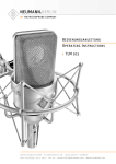
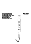
Bedienungsanleitung
Operating Instructions
KM 100 System
georg neumann gmbh · ollenhauerstr. 98 · 13403 berlin · germany
tel +49 (0)30 / 41 77 24-0 · fax -50 · [email protected] · www.neumann.com
KM 100
Inhaltsverzeichnis
Table of Contents
1.
Kurzbeschreibung
1.
Summarized Description
2.
Das Kleinmikrofon-System KM 100
2.
The KM 100 Miniature Microphone System
2.1
Allgemeines, Beschreibung
2.1
General Information, Description
2.2
Die verschiedenen aktiven Kapseln
2.2
The Various Active Capsules
2.3
Ausgangsstufe KM 100
2.3
KM 100 Output Stage
3.
Stromversorgung
3.
Power Supply
3.1
Phantomspeisung
3.1
Phantom Powering
3.2
Betrieb mit Netzgeräten
3.2
ac Supply Operation
3.3
Batteriespeisung
3.3
Battery Powering
3.4
Betrieb an unsymmetrischen oder mittengeerdeten Eingängen
3.4
Operation with Unbalanced or Center Tap
Grounded Inputs
4.
Technische Daten
4.
Technical Specifications
5.
Schaltbild KM 100
5.
Circuit Diagram KM 100
6.
Einige Hinweise zur Pflege von Mikrofonen
6.
Some Remarks on Microphone Maintenance
7.
Frequenzgänge und Polardiagramme
7.
Frequency Responses and Polar Patterns
8.
Zubehör
8.
Accessories
1.
Kurzbeschreibung
1.
A Short Description
2
Die Mikrofone werden mit 48 V, 2 mA phantomgespeist (IEC 1938). Feldbetriebsübertragungsfaktor
je nach Mikrofonkapsel 10...15 mV/Pa entsprechend –40...–36 dB re. 1 V/Pa. In den Ausgangsstufen befindet sich jeweils ein 10 dBSchalter zum Absenken des Übertragungsmaßes, in
der Ausgangsstufe KM 100 F zusätzlich ein Schalter zur Bassabsenkung. Der Dynamikumfang reicht
von ca. 16 dB-A (Ersatzgeräuschpegel) bis ca.
138 dB SPL (Grenzschalldruckpegel). Das sind
122 dB.
2.
Das Kleinmikrofon-System
KM 100
2.1 Allgemeines, Beschreibung
The microphones are phantom powered at 48 V, 2 mA
(IEC 1938). Field sensitivity, depending on capsule
10...15 mV/Pa, corresponding to –40...–36 dB re.
1 V/Pa. Both output stages incorporate a 10 dB
preattenuation switch, the KM 100 F output stage
has an additional low frequency roll-off switch.
The dynamic range extends from approximately
16 dB-A (equivalent noise level) to approximately 138 dB SPL i.e. 122 dB.
2.
The KM 100 Miniature
Microphone System
2.1 General Information, Description
KM 100 ist das variable Kondensator-KleinmikrofonSystem aus der Typenreihe „fet 100®“. Das System
ist variabel, weil es eine Reihe unterschiedlicher
Kondensatorkapseln mit verschiedenen Richtcharakteristiken anbietet und weil es eine Vielzahl an
Zubehör gibt, das zwischen die Kapseln und die
Ausgangsstufen geschraubt werden kann. Dadurch
lassen sich die Mikrofone an unterschiedlichste
Aufgaben besonders leicht und gut anpassen. Ein
eventuell im Fernsehbild, auf der Bühne oder im
Konzertsaal sichtbares Mikrofon kann besonders
unauffällig gehalten werden.
The KM 100 is the variable condenser miniature
microphone system of the “fet 100®” Series. The
system is variable because it offers a number of
different condenser capsules with various directional characteristics and because a wide range of
accessories can be supplied, which are simply
screwed between the capsules and the output
stages. The microphones can thus be easily and
effectively used for an infinitely wide variety of
purposes. A visible microphone in a television
scene, on the stage or in the concert hall can thus
be kept extremely small and unobtrusive.
KM 100 heißt Kleinmikrofon-System, weil die Mikrofone nur 92 mm lang sind und einen Durchmesser von 22 mm haben. Das Mikrofon besteht aus
der Kondensatorkapsel AK... und der Ausgangsstufe
KM 100, z. B. bilden AK 30 und KM 100 das Mikrofon KM 130. Beide Teile können auseinandergeschraubt werden. Das Kapselteil kann auf Zubehör
wie
The KM 100 is called a miniature microphone system because the microphones are a mere 92 mm
long and 22 mm in diameter. The microphone consists of the AK... condenser capsule and the
KM 100 output stage. AK 30 and KM 100, for example, make up the KM 130. Both these parts can
be unscrewed from each other. The capsule section can be screwed to accessories, such as
• Kabel,
• cables,
• Kapselverlängerungen,
• capsule extensions,
• Stativgelenke,
• stand mounts,
• Tischständer,
• table stands,
• Schwanenhälse,
• goosenecks,
• Stereohalterungen und
• stereo mounts and
KM 100 ist das variable Kondensator-Kleinmikrofon-System aus der Typenreihe „fet 100®“.
Es besteht aus: aktiven Kapseln mit den Richtcharakteristiken Kugel, breite Niere, Niere, Niere mit
abgesenktem Bassbereich, Hyperniere und Acht,
zwei unterschiedlichen Ausgangsstufen und umfangreichem Zubehör für unterschiedlichste Kapselmontage.
The KM 100 is the variable condenser miniature
microphone system of the “fet 100®” Series. It
consists of: active capsules with the directional
characteristics omnidirectional, wide-angle cardioid, cardioid, cardioid with bass roll-off, hypercardioid and figure-8, two different output stages
and a comprehensive range of accessories for
widely varying methods of capsule mounting.
Das transformatorlose Schaltungskonzept zeichnet
sich aus durch besonders niedriges Eigengeräusch
und höchste Aussteuerbarkeit, besonders saubere,
freie und verfärbungsfreie Klangübertragung. Die
Ausgangsstufen haben einen symmetrischen,
transformatorlosen Ausgang.
The main points of excellence of the transformerless circuit design are: remarkably low intrinsic
noise and high output capability and particularly
clean, free and colorless sound reproduction. The
output stages have a balanced, transformerless
output.
Der 3-polige XLR-Stecker hat jeweils folgende
Belegung:
The 3-pin XLR plug connector is wired as follows:
Pin 1: 0 V/Masse
Pin 1: 0 V/ground
• Abhängevorrichtungen
• auditorium hangers
Pin 2: Modulation (+Phase)
Pin 2: Modulation (+phase)
Pin 3: Modulation (–Phase)
Pin 3: Modulation (–phase)
geschraubt werden und ist dabei als Kapselteil nur
ca. 35 mm lang (AK 20: ca. 50 mm).
and is not more than about 35 mm long (AK 20 approximately 50 mm).
Die Ausgangsstufe kann über ein nur ca. 3 mm dikkes Kabel bis etwa 50 m vom Kapselteil abgesetzt
werden.
The output stage can be operated at a distance of
up to 50 m from the capsule section via a cable
only about 3 mm thick.
3
KM 100
Anwendungsempfehlungen für das Kleinmikrofonsystem KM 100 sind im Prospekt „KM 100 Application Guide“ beschrieben.
Application hints for using the KM 100 Miniature
microphone system are described in the catalog
“KM 100 Application Guide”.
Das KM 100-System gehört zur Typenreihe „fet
100®“, weil die Mikrofonschaltung transformatorlos arbeitet. Sie ist gekennzeichnet durch:
The KM 100 system is part of the “fet 100®” Series,
the microphone circuitry being transformerless.
The system is distinguished by:
• besonders hohe Aussteuerbarkeit bei sehr
niedrigem Eigengeräuschpegel,
• particularly high output level with very low intrinsic noise,
• besonders saubere, freie und verfärbungsfreie
Klangübertragung,
• remarkably clean and uncolored sound reproduction,
• besonders kompakten Aufbau, indem die gesamte Mikrofonschaltung als Baustein mit ca.
2 cm2 Grundfläche in Hybridbauweise zusammengefasst ist.
• extremely compact design, the entire microphone circuitry of hybrid construction is constituted by a module measuring only 2 cm 2 in
area.
Die Schaltung befindet sich jeweils im Gehäuse der
Mikrofonkapsel, die damit zur aktiven Kapsel
wird. Dadurch wird bei Verwendung nur der Kapsel, abgesetzt von der Ausgangsstufe und montiert
an einem Kabel oder auf einem Schwanenhals, die
gesamte hochwertige Mikrofonschaltung abgesetzt. Das hat zur Folge, dass die Verwendung des
Zubehörs keinerlei Einschränkung in der Übertragungsqualität bedeutet, und dass auch ein langes
Kabel zwischen aktiver Kapsel und Ausgangsstufe sehr unempfindlich gegen äußere Störfelder ist.
Erst bei Kabellängen deutlich über 50 m macht
sich bei dieser Anwendung ein Abfall im oberen
Frequenzbereich bemerkbar.
The circuitry is contained in the case of the microphone capsule, which therefore becomes an active
capsule. Thus, if the capsule is used by itself, separately from the output stage and mounted on a
cable or gooseneck, the entire high quality microphone circuitry is separated with it. The result is
that the use of the accessories entails absolutely
no impairment of the quality of reproduction and
that even a long cable connection to the active
capsule is very insensitive to external interference fields. Only when for this application cable
lengths are well in excess of 50 m is any fall-off
in the upper frequency range noticeable.
Allerdings kann die Kabellänge durch starke umgebende Störfelder (HF, kapazitive oder induktive Einkopplungen) auf deutlich kleinere Werte begrenzt werden. Dann sollte nach der mindestens erforderlichen Kabellänge auf die Ausgangsstufe
des Systems übergegangen werden, um von dort
mit der symmetrischen Modulationsleitung (z.B.
IC 3 mt) störsicher weiterzugehen. Erst bei (Neumann-) Kabellängen deutlich über 300 m macht
sich bei dieser Anwendung ein Abfall im oberen
Frequenzbereich bemerkbar.
2.2 Die verschiedenen aktiven Kapseln
4
It must be mentioned, however, that the useful cable length can be considerably reduced by strong
surrounding interference fields (RF, capacitive or
inductive coupling). In such cases, the cable length
should be kept to the bare minimum and the connection to the output stage of the system should
be made, so that from this point, interference can
be eliminated with a balanced modulation lead
(e.g. IC 3 mt). It is only when (Neumann) cables are
well over 300 m that for this application any falloff in the upper frequency range becomes apparent.
2.2 The Various Active Capsules
Es stehen folgende sieben aktive Kapseln zur Verfügung:
The following seven active capsules are available:
AK 20 ................. sw ............ Best.-Nr. 71659
Druckgradientenempfänger mit der Richtcharakteristik Acht, die mit nur einer Membran realisiert
ist. Alle Schallkomponenten wirken unmittelbar
an dieser einen Membran ohne die inneren Lauf-
AK 20 ................. blk ............. Cat. No. 71659
Pressure gradient transducer with the figure-8
characteristic, realized with a single diaphragm.
All sound field components reach the diaphragm
directly without the internal path lengths in dou-
zeiten bei Doppelmembransystemen. Der obere
Teil der AK 20 lässt sich gegenüber dem unteren
verdrehen, um die Kapsel akustisch ausrichten zu
können. Befindet sich die bedruckte Kapselhälfte
vorne und über dem Logo der Ausgangsstufe, ist
das Mikrofon phasenrichtig eingestellt und stimmt
mit anderen, seitlich besprochenen Mikrofonen
überein. Die Verbindung ist schwergängig konstruiert, so dass die Verdrehung mit einer langsamen, gleichmäßigen Bewegung und nicht
versehentlich erfolgen kann. Die Kapsel lässt sich
ohne Anschlag beliebig verdrehen.
ble diaphragm designs. The top part of the AK 20
is rotatable relative to the lower part in order to
allow acoustic alignment of the front side with
the logo on the output stage. When the front side
of the capsule with the printed figure-8 symbol is
aligned with the logo, the microphone is phasealigned and has the same polarity as other sideentrance microphones. The rotating joint is constructed with some mechanical resistance, so that
the alignment can be performed with a smooth,
slow rotating motion and cannot happen accidentally. The capsule can be rotated infinitely
through 360 degrees.
AK 30 ................. sw ............ Best.-Nr. 69001
AK 30 ist ein diffusfeldentzerrter Druckempfänger
mit einem im freien Schallfeld wirksamen Höhenanstieg (ca. 7 dB bei 10 kHz). Dadurch ist der Frequenzgang im diffusen Schallfeld bis 10 kHz eben.
AK 30 ................. blk ............. Cat. No. 69001
AK 30 is a diffuse-field equalized pressure transducer with a free-field treble boost (approx. 7 dB
at 10 kHz). The frequency response in the diffuse
sound field is flat up to 10 kHz.
AK 31 ................. sw ............ Best.-Nr. 69002
AK 31 ist ein freifeldentzerrter Druckempfänger:
Das Übertragungsmaß ist im freien Schallfeld bis
20 kHz eben, fällt dafür im diffusen Schallfeld
oberhalb 5 kHz ab.
AK 31 ................. blk ............. Cat. No. 69002
AK 31 is a free-field equalized pressure transducer. The sensitivity in the free sound field is flat up
to 20 kHz. In the diffuse sound field there is a rolloff above 5 kHz.
AK 40 ................. sw ............ Best.-Nr. 69007
AK 40 ist ein Druckgradientenempfänger mit Richtcharakteristik Niere. Sehr gleichmäßige, zur 0°Schalleinfallsrichtung parallele Frequenzkurven.
Damit wird der Aufnahmesektor bis ± 135° ohne
Klangfärbungen übertragen.
AK 40 ................. blk ............. Cat. No. 69007
AK 40 is a pressure gradient transducer with cardioid characteristic. The frequency curves are very
even and parallel to 0° sound incidence. Sound
sources within a pickup angle of ± 135° are transmitted without coloration.
AK 43 ................. sw ............ Best.-Nr. 69014
AK 43 ist ein Druckgradientenempfänger mit Richtcharakteristik Breite Niere. Die Dämpfung beträgt
4 dB bei 90°, 8 dB bei 135° und 11 dB bei 180°.
Die Frequenzgangkurven für den von vorn einfallenden Schall (±90°) sind bis 12 kHz parallel.
AK 43 ................. blk ............. Cat. No. 69014
The AK 43 is a pressure gradient transducer with
wide-angle cardioid characteristic. Attenuation:
4 dB at 90°, 8 dB at 135°, and 11 dB at 180°. The
frequency response for sound sources within an
angle of ±90° (off axis) is parallel up to 12 kHz.
AK 45 ................. sw ............ Best.-Nr. 69015
AK 45 ist ein Druckgradientenempfänger mit Richtcharakteristik Niere wie AK 40. Eine akustische
Tiefenabsenkung im Freifeld dient der Unterdrükkung von tieffrequenten Störungen (Windgeräusche, Körperschall). Durch den bei Druckgradientenmikrofonen physikalisch bedingten Naheffekt
ergibt sich bei Nahbesprechung aus ca. 15 cm Abstand ein ebener Frequenzgang (Sprachniere).
AK 45 ................. blk ............. Cat. No. 69015
AK 45 is a pressure gradient transducer with cardioid characteristic just like the AK 40. However,
it has an acoustic bass roll-off characteristic in the
free field and therefore suppresses interfering LF
noise (wind, structure-borne noise). Since proximity effect is a natural feature of pressure gradient
microphones, the AK 45 appears to be optimized
for a flat frequency response at a recording distance of approximately 15 cm (speech cardioid).
AK 50 ................. sw ............ Best.-Nr. 69016
AK 50 ist ein Druckgradientenempfänger mit Richtcharakteristik Hyperniere. Dämpfung für Schall
AK 50 ................. blk ............. Cat. No. 69016
AK 50 is a pressure gradient transducer with a hypercardioid characteristic. Attenuation of sound
5
KM 100
von den Seiten und von hinten jeweils ca. 10 dB.
Minimale Empfindlichkeit bei ca. 120° Schalleinfallsrichtung.
2.3 Ausgangsstufe KM 100
incidence from the side or rear is approximately
10 dB. Minimum sensitivity occurs at an angle of
about 120°.
2.3 KM 100 Output Stage
KM 100 .............. sw ............ Best.-Nr. 07395
An der Seite der Ausgangsstufe KM 100 befindet
sich ein versenkter und damit gegen unbeabsichtigtes Verstellen gesicherter Schiebeschalter. Mit
ihm kann eine Vordämpfung von 10 dB eingestellt
werden. Die Dämpfung wird erreicht, indem die
Kapselspannung auf ein Drittel ihres Wertes reduziert wird. Die Mikrofone können dann Schalldruckpegel bis ca. 150 dB verzerrungsfrei übertragen (siehe technische Daten).
3.
Stromversorgung
3.1 Phantomspeisung
3.
Power Supply
3.1 Phantom Powering
Die Mikrofone der Serie „fet 100®“ werden mit
48 V phantomgespeist (P48, IEC 1938).
The “fet 100®” Series microphones are phantompowered at 48 V (P48, IEC 1938).
Bei der Phantomspeisung fließt der Speisestrom
vom positiven Pol der Spannungsquelle über die
elektrische Mitte der beiden Modulationsadern
zum Mikrofon. Er wird hierzu über zwei gleichgroße Widerstände beiden Tonadern gleichsinnig zugeführt. Die Rückleitung des Gleichstroms erfolgt
über den Kabelschirm. Zwischen beiden Modulationsadern besteht also keine Potentialdifferenz.
Daher ist mit der Phantomspeisung eine kompatible Anschlusstechnik möglich:
With phantom powering the dc from the positive
supply terminal is divided via two identical resistors, one half of the dc flowing through each audio (modulation) conductor to the microphone, and
returning to the voltage source via the cable
shield. Phantom powering provides a fully compatible connecting system, since no potential differences exist between the two audio conductors.
Auf die Anschlussdosen können wahlweise auch
dynamische Mikrofone oder Bändchenmikrofone
sowie die Modulationskabel röhrenbestückter
Kondensatormikrofone geschaltet werden, ohne
dass die Speisegleichspannung abgeschaltet werden muss.
Studio outlets so powered will therefore also accept dynamic microphones and ribbon microphones as well as the modulation conductors of
tube-equipped condenser microphones without the
need to switch off the dc supply voltage.
Der Ausgang eines Neumann-Phantomspeisegerätes darf auch auf bereits anderweitig phantomgespeiste Mikrofoneingänge gesteckt werden.
3.2 Betrieb mit Netzgeräten
6
KM 100 .............. blk ............. Cat. No. 07395
On the side of the output stage KM 100 is a slide
switch which is recessed to prevent inadvertent
alteration. This can be used to effect 10 dB preattenuation. Attenuation is achieved by reducing
the capsule voltage to one third of nominal. The
microphones can then reproduce sound pressure
levels of up to 150 dB without distortion (see technical data).
No harm is done even if a Neumann phantom power supply is connected to the inputs of microphones which are phantom powered from another
source.
3.2 ac Supply Operation
Für die Stromversorgung sind alle P48-Netzgeräte geeignet, die mindestens 2 mA je Kanal abgeben.
All P48 power supplies in accordance with IEC 1938
which provide at least 2 mA per channel, are suitable for powering the microphones.
Das Neumann P48-Netzgerät hat die Bezeichnung
N 248. Es ist zur Stromversorgung zweier Mono-
The Neumann P48 power supply unit bears the
designation N 248. It is designed to power two
Kondensatormikrofone oder eines Stereomikrofons mit 48 V ± 1 V, maximal 2 x 6 mA, geeignet (siehe auch Neumann-Druckschrift 68832:
„48 V-Phantomspeisegeräte“).
mono condenser microphones or one stereo microphone at 48 V ± 1 V, max. 2 x 6 mA (see also Neumann bulletin no. 68832: ”Phantom 48 VDC Power Supplies“).
Die Zuordnung der Mikrofonanschlüsse und die Polarität der Modulationsadern ist am Ausgang des
Speisegerätes die gleiche wie am Mikrofon.
The assignment of the microphone terminals and
the modulation polarity at the power supply output are identical to those at the microphone.
Das Netzgerät N 248 versorgt ein oder zwei Mikrofone mit 48 V-Phantomspeisung P48. Alle Anschlüsse mit XLR 3-Flanschdosen. Die Modulationsausgänge sind gleichspannungsfrei.
The N 248 supplies one stereo microphone, or two
mono condenser microphones with 48 V phantom
power (P48). All connectors are of XLR 3 type. The
audio signal outputs are DC-free.
N 248 ................. sw ............ Best.-Nr. 08537
N 248 ................. blk ............. Cat. No. 08537
3.3 Batteriespeisung
3.3 Battery Powering
Steht keine Netzspannung zur Verfügung, kann die
Speisung mit einem der Geräte
If a mains power source is not available, power
can be supplied by one of the battery units
BS 48 i .................................. Best.-Nr. 06494
(für ein Mikrofon)
BS 48 i .................................... Cat. No. 06494
(for one microphone)
BS 48 i-2 ............................... Best.-Nr. 06496
(für zwei Mikrofone)
erfolgen. Beide Geräte liefern 48 V ± 1 V, maximal
je 5 mA, und werden jeweils von einer 9 VoltBlockbatterie Typ IEC 6 F 22 gespeist.
BS 48 i-2 ................................. Cat. No. 06496
(for two microphones)
Both units deliver 48 V ± 1 V, at 5 mA maximum,
and are powered by a 9-volt monobloc battery
Type IEC 6 F 22.
Das Gerät BS 48 i-2 ist mit 5-poligen, das BS 48 i
mit 3-poligen XLR-Steckverbindern ausgerüstet.
(Siehe auch Neumann-Druckschrift 68832... „48 VPhantomspeisegeräte“).
The BS 48 i-2 is equipped with 5-pin XLR connectors, the BS 48 i with 3-pin XLR connectors. (See
Neumann bulletin 68832... “Phantom 48 VDC Power Supplies”.)
Die Zuordnung der Mikrofonanschlüsse und die Polarität der Modulationsadern ist am Ausgang der
Speisegeräte die gleiche wie am Mikrofon.
The assignment of the microphone terminals and
the modulation polarity at the power supply output are identical to those at the microphone.
3.4 Betrieb an unsymmetrischen oder
mittengeerdeten Eingängen
3.4 Operation with Unbalanced
or Center Tap Grounded Inputs
Die 48 V-Phantom-Speisegeräte BS 48 i, BS 48 i-2
und N 248 haben gleichspannungsfreie Ausgänge,
so dass für den Anschluss an unsymmetrische Eingänge kein Übertrager erforderlich ist.
The BS 48 i, BS 48 i-2 and N 248 phantom 48 Vdc
power supplies are dc-free so that no transformer
is required for connection to unbalanced inputs.
ACHTUNG:
NOTE:
Bei Mikrofonen der Serie „fet 100®“ mit der Ausgangsstufe KM 100 ist Pin 3 die heiße Phase und
Pin 2 muss an Masse gelegt werden (siehe Abbildung 1). Dies bedeutet eine um 180° gedrehte Phasenlage bei unsymmetrischem Betrieb gegenüber
anderen Studiomikrofonen. Beim Mischen muss diese
Phasenlage berücksichtigt werden.
With microphones of the “fet 100®” Series, pin 3
is the hot phase, and pin 2 must be connected to
earth (see Fig. 1). This means that the phase relationship on unbalanced operation is reversed by
180° in comparison with other studio microphones. When mixing, phase reversal has to be taken into account.
7
b) In jede abgehende
Modulationsleitung kann
zur Abblockung der 48 VGleichspannung eine RCKombination eingefügt
werden (siehe Abbildung 2 und Neumann-Information Nr. 84 221).
8
b) In every outgoing
modulation lead, an RC
net-work can be incorporated to block the 48 Vdc
voltage (See Figure 2
and Neumann-Information no. 84 222).
Abbildung / Figure 2
50 Ohm
68 dB
76,5 dB
26 dB
Nennimpedanz / Rated impedance
Geräuschpegelabstand2), CCIR3)
Signal-to-noise ratio2), CCIR3)
Geräuschpegelabstand2), A-bewertet3)
Signal-to-noise ratio2), A-weighted3)
Ersatzgeräuschpegel, CCIR3)
Equivalent noise level, CCIR3)
100 g
80 g
2 mA
124 dB
140 dB
150 dB
16 dB-A
27 dB
78 dB
67 dB
5)
4)
3)
2)
bei 1 kHz an 1 kOhm Nennlastimpedanz.
bezogen auf 94 dB SPL
nach IEC 60268-1; CCIR-Bewertung nach CCIR 468-3, Quasi-Spitzenwert;
A-Bewertung nach IEC 61672-1, Effektivwert
Klirrfaktor des Mikrophonverstärkers bei einer Eingangsspannung, die der von der
Kapsel beim entsprechenden Schalldruck abgegebenen Spannung entspricht.
Phantomspeisung (P48, IEC 61938).
5)
4)
3)
2)
92 x 22 mm
80 g
2 mA
121 dB
138 dB
148 dB
17 dB-A
26 dB
77 dB
68 dB
50 Ohm
92 x 22 mm
80 g
2 mA
124 dB
142 dB
152 dB
18 dB-A
27 dB
76 dB
67 dB
50 Ohm
10 mV/Pa
KM 150
at 1 kHz into 1 kohms rated load impedance.
re 94 dB SPL
according to IEC 60268-1; CCIR-weighting acccording to CCIR 468-3, quasi peak;
A-weighting according to IEC 61672-1, RMS
THD of microphone amplifier at an input voltage equivalent to the capsule output
at the specified SPL.
Phantom powering (P48, IEC 61938).
1)
92 x 22 mm
80 g
2 mA
122 dB
138 dB
148 dB
16 dB-A
25 dB
78 dB
69 dB
50 Ohm
14 mV/Pa
20 ... 20.000 Hz
15 mV/Pa
94 dB SPL 1 Pa = 10 μbar, 0 dB 20 μPa
92 x 22 mm
80 g
2 mA
122 dB
138 dB
148 dB
16 dB-A
25 dB
78 dB
69 dB
50 Ohm
15 mV/Pa
KM 145
Druckgradientenempfänger
Pressure gradient transducer
KM 140
1)
92 x 22 mm
80 g
2 mA
124 dB
140 dB
150 dB
16 dB-A
25 dB
78 dB
69 dB
50 Ohm
12 mV/Pa
KM 143
94 dB SPL 1 Pa = 10 μbar, 0 dB 20 μPa
110 x 24 mm 92 x 22 mm
Gewicht / Weight
Abmessungen / Dimensions (L x ø)
2 mA
122,5 dB
Dynamikumfang des Mikrophonverstärkers
Total dynamic range ot the microphone amplifier
Stromaufnahme5) / Current consumption5)
140 dB
150 dB
Grenzschalldruckpegel für 0,5 % Klirrfaktor4)
Max. SPL for less than 0.5 % THD4)
mit Vordämpfung / with preattenuation
17,5 dB-A
12 mV/Pa
50 Ohm
20 ... 20.000 Hz
12 mV/Pa
Feldübertragungsfaktor1) / Sensitivity1)
Ersatzgeräuschpegel, A-bewertet3)
Equivalent noise level, A-weighted3)
KM 131
Druckempfänger
Pressure transducer
Übertragunsbereich / Frequency range
Druckgradientenempfänger
Pressure gradient transducer
KM 130
a) In center tap grounded equipment with input
transformer (e.g. some
NAGRA units), the earth
lead can almost always
be disconnected without
affecting the function of
the equipment.
Richtcharakteristik
Directional pattern
a) In mittengeerdeten
Geräten mit Eingangsübertrager (z.B. einige
NAGRA-Geräte) kann die
betreffende Erdverbindung fast immer ohne
Nachteile für die Funktion
des Gerätes aufgetrennt
werden.
4.
KM 120
Bei vielen anderen als den o.g. PhantomspeisegeIn the case of many other phantom powering units
räten liegen nicht nur die Modulationsleitungen
(except those mentioned above), not only the modzum Mikrofon auf dem Potential der Speisespanulation leads to the microphone, but also the outnung von +48 V, sondern
going modulation leads
auch die vom Speisegefrom the powering unit,
rät abgehenden Modulaare at the potential of the
tionsleitungen. Für die in
feed voltage (+48 V).
der Studiotechnik allgeThis is of no significance
mein üblichen symmetrifor the balanced, floating
schen und erdfreien Veramplifier and mixing constärker und Mischpulteinsole inputs in general
gänge ist dies ohne
studio use. On the other
Bedeutung.
Dagegen
hand, the feed voltage
Abbildung / Figure 1
wird die Speisespannung
will be short-circuited
beim Anschluss an einwhen connected to sinseitig oder mittengeerdete Verstärkereingänge
gle-ended or center tap grounded amplifier inputs,
kurzgeschlossen, und es ist kein Betrieb möglich.
and no operation will be possible. This can be cirDann bestehen folgende Lösungsmöglichkeiten:
cumvented as follows:
Akustische Arbeitsweise
Acoustic operating principle
Typ / Type
KM 100
Technische Daten / Technical Specifications
9
KM 100
5.
Schaltbild / Circuit Diagram KM 100
6.
Einige Hinweise zur Pflege von
Mikrofonen
Hints on Microphone Maintenance
Staubschutz verwenden: Mikrofone, die nicht im
Einsatz sind, sollte man nicht auf dem Stativ einstauben lassen. Mit einem Staubschutzbeutel
(nicht fusselnd) wird dies verhindert. Wird ein Mikrofon längere Zeit nicht verwendet, sollte es
staubgeschützt bei normalem Umgebungsklima
aufbewahrt werden.
Use a dust cover: Microphones not in use should
not be left on the stand gathering dust. This can
be prevented by the use of a non-fluffy dust cover. When not in use for a longer period, the microphone should be sealed against dust and stored
under standard climatic conditions.
Popschutz verwenden: Ein Popschutz hat nicht nur
die Aufgabe, bei Gesangsaufnahmen die Entstehung von Poplauten zu verhindern. Er vermeidet
auch effizient, dass sich von der Feuchtigkeit des
Atems bis hin zu Essensresten unerwünschte Partikel auf der Membran ablagern.
Use a pop screen: A pop screen not only prevents
the occurrence of plosive pop noises in vocal recordings, but also efficiently prevents unwanted
particles, from respiratory moisture to food remnants, from settling on the diaphragm.
Keine überalterten Windschutze verwenden: Auch
Schaumstoff altert. Das Material kann brüchig und
krümelig werden. Anstatt das Mikrofon zu schützen, kann er dann zur Verunreinigung der
Mikrofonkapsel führen. Überalterte Windschutze
also bitte entsorgen.
Avoid the use of old wind shields: As the foam
material of a wind shield ages it can become brittle and crumbly. Instead of protecting the microphone, an old wind shield can thus lead to soiling
of the microphone capsule. Therefore please dispose of worn-out wind shields.
Funktionstest: Moderne Kondensatormikrofone
nehmen durch lautes Ansprechen keinen Schaden.
Zur Kontrolle, ob ein solches Mikrofon angeschlossen ist, sollte man es aber keinesfalls anpusten
oder anpoppen, da dies einem akustischen Signal
von mehr als 140 dB (!) entsprechen kann. Normale Sprache genügt zum Funktionstest völlig.
Function testing: Although modern condenser microphones are not harmed by high sound pressure
levels, one should under no circumstances use a
pop-test to check whether the microphone is connected and the channel on the mixing console is
pulled up, since this can result in sound pressure
levels of over 140 dB! Normal speech is quite sufficient for function testing.
Selbsthilfe kann teuer sein! Leider kommt es doch
vor, dass durch eine Selbstreparatur mehr beschädigt als behoben wird. Insbesondere das Reinigen
verschmutzter Kapseln erfordert viel Erfahrung und
die Hand eines Fachmanns. Der Lackschutz auf
Platinen zeigt u.a. an, dass dort nicht gelötet werden darf. Einige Bauteile sind speziell selektiert
und können nicht durch Material von der Stange
ersetzt werden. Um unnötige Kosten zu vermeiden,
empfiehlt sich die Einsendung an unsere Vertretungen oder an uns.
Inspektion durchführen lassen: Regelmäßiges
Durchchecken des Mikrofonbestands, wie es einige Schauspielhäuser und Rundfunkanstalten praktizieren, kann bei der Früherkennung von Schäden
helfen. Leichte Verschmutzungen lassen sich eher
beseitigen, als eine untrennbar in die Membran
eingebrannte Nikotinschicht. Insbeson-dere bei
Mikrofonen im Verleih und in verunreinigenden
Umgebungen empfiehlt sich die regelmäßige Kontrolle, deren Kosten im Vergleich zu einer aufwendigen Reparatur sehr gering sind.
10
7.
Do-it-yourself repairs can be expensive! Unfortunately, do-it-yourself repairs sometimes do more
harm than good. Cleaning soiled capsules in particular requires considerable experience and an
expert touch. The protective lacquer on circuit
boards indicates, among other things, places
which must not be soldered. Certain components
are specially selected and cannot be replaced by
standard parts. To avoid unnecessary expense, we
recommend sending defective microphones to us
or our representatives for servicing.
Regular inspections: Sending in microphones regularly for inspection, as practiced by some theaters
and broadcasting corporations, can aid in the early detection of damage. Slight soiling can be removed much more easily than a nicotine layer inextricably bonded to the diaphragm. Regular inspections are particularly to be recommended for
microphones which are rented or are used in dusty
or smoky environments, since the costs are low in
comparison with the cost of a major overhaul.
11
KM 100
7.
Frequenzgänge und Polardiagramme / Frequency Responses and Polar Patterns
KM 120
KM 140
gemessen im freien Schallfeld nach IEC 60268-4
measured in free-field conditions (IEC 60268-4)
12
KM 130
KM 143
KM 131
KM 145
13
KM 100
8.
KM 150
KM 130 mit/with SBK 130 A
KM 131 mit/with SBK 130 A
Zubehör
Accessories
Zubehör-Liste
Accessories Listing
8.1
Kabel
8.1
Cables
8.2
Matrixverstärker MTX 191 A
8.2
MTX 191 A Matrix Amplifier
8.3
Kapselverlängerungen KVF...
8.3
KVF... Capsule Extensions
8.4
Stativgelenke SG..., DS... und SGE 100
8.4
SG..., DS... and SGE 100 Stand Mounts
8.5
Tischflansch, Tisch- und Fußbodenständer
MF..., MF-AK und TF 221 c
8.5
Table Flange, Table and Floor Stands
MF..., MF-AK und TF 221 c
8.6
Stativverlängerungen STV...
8.6
STV... Stand Extensions
8.7
Schwanenhälse SMK..., MZEF...
8.7
SMK..., MZEF... Goosenecks
8.8
Stereohalterungen für zwei abgesetzte
Kapseln STH...
8.8
STH... Stereo Mounts for two Remote Capsule
Sections
8.9
Mikrofonneigevorrichtungen MNV...
8.9
MNV... Auditorium Hangers
8.10
Standrohr SR 100 und Kabeladapter KA 100
8.10
SR 100 Stand Tube and KA 100 Cable Adapter
8.11
Elastische Aufhängung EA...
8.11
EA... Elastic Suspension
8.12
Windschirme WNS... und WS 100
8.12
WNS... and WS 100 Windscreens
8.13
Popschutz PS 15
8.13
PS 15 Popscreen
8.14
Schallbeugungskugel SBK 130
8.14
SBK 130 Sound Diffraction Sphere
Zubehör-Beschreibung
Accessories Description
8.1
8.1
Kabel
8.1.1 Kabel IC 3 mt zum Anschluss des kompletten
Mikrofons bzw. der Ausgangsstufe
Cables
8.1.1 IC 3 mt Cable for Connecting the Complete
Microphone or the Output Stage
Die akustischen Eigenschaften der Mikrofone
werden auch durch sehr lange (Neumann-) Kabel
nicht beeinflusst. Erst bei Kabellängen deutlich
über 300 m macht sich ein Abfall im oberen Frequenzbereich bemerkbar.
The electroacoustic properties of the microphones are not affected even by very long (Neumann) cables. However, if cables are well over
300 m, a fall-off in the upper frequency range
becomes apparent.
Andere Kabellängen und Kabelmaterial ohne
Steckverbinder sind auf Wunsch lieferbar.
Special cable lengths and cable material without connectors can be made to order.
Weitere Artikel sind im Katalog „Zubehör“ beschrieben.
Further articles are described in the “Accessories” catalog.
IC 3 mt ................ sw ......... Best.-Nr. 06543
Mikrofonkabel mit Doppeldrallumspinnung als
Abschirmung. Ø 5 mm, Länge 10 m. XLR 3 Steckverbinder, schwarzmatt.
IC 3 mt ................. blk ........... Cat. No. 06543
Microphone cable with double twist (double helix) braiding as shield. Ø 5 mm, length 10 m.
XLR 3 connectors, matte black.
8.1.2 Kabel LC 3 KA zum Anschluss des
abgesetzten Kapselteils an die Ausgangsstufe
14
8.
8.1.2 LC 3 KA Cable for Connecting the
Remote Capsule Section to the Output Stage
15
KM 100
Die aktive Kapsel kann von der Ausgangsstufe
abgesetzt betrieben werden. Dazu wird das Verbindungskabel LC 3 KA benötigt.
The active microphone capsule can be operated
remotely from the output stage, for which the
LC 3 KA connecting cable is required.
LC 3 KA (5 m) ..... sw ......... Best.-Nr. 08408
LC 3 KA (10 m) ... sw ......... Best.-Nr. 08409
Das LC 3 KA verbindet aktive Kapseln AK... mit
der Ausgangsstufe KM 100. Ø 3,5 mm, Länge
5 oder 10 m.
LC 3 KA (5 m) ..... blk ........... Cat. No. 08408
LC 3 KA (10 m) ... blk ........... Cat. No. 08409
The LC 3 KA connects active capsules AK... with
the KM 100 output stage. Ø 3.5 mm, length 5 or
10 m.
Das RSM 191 wird über 7-polige Kabel KT 5/KT 6
angeschlossen, zwei aktive Kapseln AK... mit
dem Kabel AC 30. Der Modulationsausgang erfolgt über einen XLR 5 M-Flanschstecker. Der
Modulationsausgang ist gleichspannungsfrei.
Für den Anschluss an unsymmetrische Eingänge
stehen Adapterkabel AC... zur Verfügung.
8.3
8.1.3 Adapterkabel AC 30 zum Anschluss der
Stereokombination an MTX 191 (A)
8.1.3 AC 30 Adapter Cable to connect a Stereo
Combination with MTX 191 (A)
AC 30 (5 m) ....................... Best.-Nr. 08418
Y-Kabel, 5 m lang, zum Anschluss aktiver Kapseln, z.B. AK 20 und AK 40 als MS-Stereokombination an den Matrixverstärker MTX 191 (A).
Wahlweise XY- oder MS-Signale liegen dann am
Ausgang des MTX 191 (A) vor. Der Aufnahmewinkel wird elektrisch fernumgeschaltet. Die
Ausgangsstufen KM 100 werden nicht benötigt.
Kennzeichnung: gelb für Kanal 1 (Niere), rot für
Kanal 2 (Acht).
8.2
16
Matrixverstärker MTX 191 A
AC 30 (5 m) ......................... Cat. No. 08418
Y-cable, 5 m long, to connect two active capsules, e.g. AK 20 and AK 40 as MS stereo couple
directly to the MTX 191(A) matrix amplifier. XY or
MS signals are then available at the XLR 5 output connector of the MTX 191 (A). The recording
angle is electrically remote controlled. KM 100
output stages are not required. Markings: yellow
for channel 1 (cardioid), red for channel 2 (figure-8).
8.2
MTX 191 A Matrix Amplifier
Kapselverlängerungen KVF...
The RSM 191 is connected with the 7-pin KT 5/
KT 6 cables. Two AK... active capsules can be
connected with an AC 30 cable. The audio is
passed through a XLR 5 M connector. The output
signal is DC-free. Use AC ... adapter cables to
connect the audio to unbalanced inputs.
8.3
KVF... Capsule Extensions
Mit Hilfe der Kapselverlängerungen KVF... kann
eine aktive Kapsel ohne weitere Kabel von der
Ausgangsstufe abgesetzt montiert werden. Der
starre Teil der Kapselverlängerung hat einen
Durchmesser von 6,5 mm, der biegsame Teil
(Schwanenhals) einen von 8 mm.
With the aid of the KVF... capsule extensions, an
active capsule can be mounted separately from
the output stage without the need for an additional cable. The rigid part of the capsule extension is 6.5 mm in diameter, the flexible part
(gooseneck) 8 mm.
KVF 118 KA ........ sw ......... Best.-Nr. 08410
Die gestreckte Länge der KVF 118 KA beträgt ca.
300 mm. Kabellänge: 2,2 m.
KVF 118 KA ........ blk ........... Cat. No. 08410
The extended length of the KVF 118 KA is approximately 300 mm. Cable length: 2.2 m.
Montage an SG 100(-1)/DS 100-1.
Mounted on SG 100(-1)/DS 100.
KVFF 148 KA ....... sw ......... Best.-Nr. 08412
Die Kapselverlängerung KVFF 148 KA unterscheidet sich von KVF 118/158 KA durch einen
zweiten biegsamen Bereich von ca. 100 mm auf
etwa halber Länge des starren Teils. Gestreckte
Länge ca. 570 mm. Kabellänge: 1,9 m.
KVFF 148 KA ....... blk ........... Cat. No. 08412
The extended length of the KVFF 148 KA is approximately 570 mm. It differs from the KVF 118/
158 KA by providing a second flexible section of
approximately 100 mm at about the middle of
the rigid section. Cable length: 1.9 m.
Montage an SG 100(-1)/DS 100-1.
Mounted on SG 100(-1)/DS 100.
KVF 158 KA ........ sw ......... Best.-Nr. 08411
Die gestreckte Länge der KVF 158 KA beträgt ca.
700 mm. Kabellänge: 1,8 m.
KVF 158 KA ........ blk ........... Cat. No. 08411
The extended length of the KVF 158 KA is approx.
700 mm. Cable length: 1.8 m.
Montage an SG 100(-1)/DS 100-1.
Mounted on SG 100(-1)/DS 100.
MTX 191 A .......... sw ......... Best.-Nr. 07331
Der Matrixverstärker MTX 191 A dient zur Matrizierung der MS-Mikrofonsignale des RichtrohrStereomikrofons RSM 191 bzw. der aktiven Kapseln AK 20 und AK 40. Der Pegel des Seitensignals kann unabhängig von der Wahl der
Ausgangssignale (MS oder XY) verändert werden.
Dies geschieht mit einem Drehschalter in 3-dBSchritten von –9 dB bis +6 dB relativ zum Pegel
des Mittensignals. Der Aufnahmewinkel ist in
Stufen zwischen 60° und 170° einstellbar.
MTX 191 A .......... blk ........... Cat. No. 07331
The MTX 191 A matrix amplifier is used for processing the MS microphone signals of the
RSM 191 shotgun stereo microphone, or the active capsules AK 20 and AK 40. The level of the
side signal is variable, independent of which
output mode is selected (MS or XY). It is adjusted through a rotary switch in 3 dB steps from
–9 dB to +6 dB, relative to the level of the middle signal. Consequently the pickup angle is varied in steps between 60° and 170°.
Am Ausgang liegt wahlweise das MS- oder das
XY-Signal, welches durch Summen- (X = M + S)
bzw. Differenzbildung (Y = M – S) aus dem MS-Signal gewonnen wird. Die Umschaltung erfolgt mit
einem Drehschalter auf der Frontseite. In beiden
Positionen kann eine Links-Rechts-Vertauschung
geschaltet werden, falls das Mikrofon während
der Aufnahme um seine Achse gedreht wird.
Depending on the position of the rotary switch
on the front of the matrix amplifier the output
provides either an MS- or XY-signal. The XY-signal is obtained from the MS-signal by summation (X = M + S) or subtraction (Y = M – S). In both
modes an electric left-right-inversion is alternatively possible if during the recording the microphone is turned upside-down.
SG 21 bk .............. sw ......... Best.-Nr. 08613
(gehört zum Lieferumfang)
Das Stativgelenk SG 21 bk besitzt eine Kunststoffklammer zur Aufnahme von Kleinmikrofonen. Es hat einen Gewindeanschluss 5/8"-27Gang, mit Adapter für 1/2"- und 3/8"-Stative.
SG 21 bk .............. blk ........... Cat. No. 08613
(included in the supply schedule)
Swivel mount with a plastic clamp for miniature
microphones. It has a 5/8"-27 female thread,
plus a thread adapter to connect to 1/2"- and
3/8" stands.
Gegen tieffrequente Störgeräusche ist ein
schaltbares Hochpassfilter 40(LIN)/80/200 Hz
eingebaut. Matrixverstärker Mikrofon werden
durch eine 9 V-Blockbatterie IEC 6 F 22 oder
durch externe 48 V-Phantomspeisung versorgt.
To suppress low frequent interfering noise the
matrix amplifier has a switchable high-pass filter at 40(LIN)/80/200 Hz. The power for both
matrix amplifier and microphone, is either supplied by a 9 V battery (IEC 6 F 22), or through external 48 V phantom powering.
DS 120 ................ sw ......... Best.-Nr. 07343
Das DS 120 hat eine 150 mm lange Schiene, mit
zwei verschiebbaren 1/2"-Gewindeschrauben
zur Befestigung zweier Mikrofone in ihren Halterungen. Abstand und Winkel für die Anordnung
der Mikrofone sind wählbar. Der Gewindean-
DS 120 ................ blk ........... Cat. No. 07343
The DS 120 has a 150 mm long support bar with
two movable 1/2" threaded studs. Two microphones in their mounts can be attached. Any
space or angle between the microphones is freely adjustable. The DS 120 has a 5/8"-27 female
8.4
Stativgelenke
8.4.1 Stativgelenke für das komplette Mikrofon
8.4
Stand Mounts
8.4.1 Swivel Stand Mounts for the Complete
Microphone
17
KM 100
schluss hat 5/8"-27-Gang, mit Adapter für 1/2"und 3/8"-Stative.
8.4.2 Stativgelenke für das abgesetzte Kapselteil
SG 109 ................ sw ......... Best.-Nr. 08614
Stativgelenk für abgesetzte Kleinmikrofonkapseln. Es hat einen 3/8"-Gewindeanschluss.
SGE 100 .............. sw ......... Best.-Nr. 06742
Stativgelenk für eine Aktive Kapsel des KM 100Systems. Ein Schwinggummi dient zur Unterdrükkung von Körperschallübertragung. Es hat einen
M 6-Gewindeanschluss. Bei der Befestigung auf
dem Mikrofonfuß MF 2 wird der dort befindliche
Schwinggummi entfernt und durch das SGE 100
ersetzt.
8.4.3 Stativgelenke SG 100, DS 100-1 für die
Kapselverlängerungen KVF...
SG 109 ................ blk ........... Cat. No. 08614
Swivel mount for detached miniature microphone capsules. It has a 3/8" thread.
SGE 100 .............. blk ........... Cat. No. 06742
Swivel mount for active capsules of the KM 100
system. A rubber shock mount suppresses structure-borne noise. The swivel mount has an M 6
thread (6 mm). Attaching the swivel mount to the
MF 2 table stand, the SGE 100 replaces the rubber shock mount of the table stand.
8.4.3 SG 100, DS 100-1 Swivel Stand Mounts for
the Capsule Extensions
DS 100-1 ............. blk ........... Cat. No. 08491
Mount to attach two KVF.. capsule extensions of
the KM 100 system onto a tripod. Especially suited for holding long KVF.. It is easy to arrange the
capsule extensions in parallel or facing each other. The double mount has a 5/8"-27 female
thread, plus a thread adapter to connect to 1/2"and 3/8" stands.
SG 100 ................ sw ......... Best.-Nr. 06688
Stativgelenk zur Befestigung einer Kapselverlängerung KVF... des KM 100-Systems auf Stativen, der Gewindeanschluss hat 5/8"-27-Gang,
mit Adapter für 1/2"- und 3/8"-Stative.
SG 100 ................ blk ........... Cat. No. 06688
Swivel mount to attach capsule extensions KVF...
of the variable KM 100 miniature microphone
system to tripods. It has a 5/8"-27 thread, plus a
thread adapter to connect to 1/2"- and 3/8"
stands.
SG 100-1 ............. sw ......... Best.-Nr. 08490
Stativgelenk zur Befestigung einer Kapselverlängerung KVF ... des KM 100-Systems auf Stativen. Insbesondere zur stabilen Montage langer
KVF geeignet. Das SG 100-1 hat einen Gewindeanschluss 5/8"-27-Gang, mit Adapter für 1/2"und 3/8"-Stative.
SG 100-1 ............. blk ........... Cat. No. 08490
Mount to attach a KVF.. capsule extensions of the
KM 100 system onto a tripod. Especially suited
for holding long KVF.. It has a 5/8"-27 thread,
plus a thread adapter to connect to 1/2"- and
3/8" stands.
SG-AK .................. sw ......... Best.-Nr. 08452
Das Schwenkgelenk wird zwischen Aktiver Kapsel und Ausgangsstufe des KM 100 Systems ein-
gefügt. Die Kapsel kann um max. 90° geschwenkt und ausgerichtet werden. Mit elastischer Aufhängung und Tischflansch ist eine mechanisch entkoppelte, unauffällige Untertischmontage möglich, z.B. für Sprecheranwendungen.
Länge 45 mm, Ø 22 mm.
8.4.2 Swivel Stand Mounts for the Remote Capsule
Section
DS 100-1 ............. sw ......... Best.-Nr. 08491
Stativgelenk zur Befestigung zweier Kapselverlängerungen KVF ... des KM 100-Systems auf Stativen. Insbesondere zur stabilen Montage langer
KVF geeignet. Die Kapselverlängerungen können
parallel oder einander gegenüberstehend ausgerichtet werden. Das DS 100-1 hat einen Gewindeanschluss 5/8"-27-Gang, mit Adapter für 1/2"und 3/8"-Stative.
8.4.4 Schwenkgelenk SG-AK
18
thread, plus a thread adapter to connect to 1/2"and 3/8" stands.
8.5
Tischflansch, Tisch- und Fußbodenständer
8.5.1 Tisch- und Fußbodenständer
SG-AK .................. blk ........... Cat. No. 08452
The SG-AK swivel mount can be inserted between active capsules and the output stage of
8.5
Table Flange, Table and Floor Stands
8.5.1 Table and Floor Stands
MF 2 .................... sw ......... Best.-Nr. 07266
Kleiner Tischständer mit Messingfuß, sehr standsicher. Der Ständer ist schwarzmatt lackiert und
steht gleitfest auf einer Moosgummischeibe. Der
1/2"-Gewindezapfen zur Aufnahme z.B. des Stativgelenkes SG 21/17 mt ist zur Körperschallunterdrückung durch ein Gummielement vom Fuß
entkoppelt. Ø 60 mm, Gewicht 340 g.
MF 2 .................... blk ........... Cat. No. 07266
Small table stand with brass base, very sturdy.
It has a black matte finish. The bottom is fitted
with a non-slip rubber disk. The stand has a 1/2"
threaded stud for mounting the SG 21/17 mt, for
example. The rubber shock mount between the
stud and the base serves to suppress structureborne noise. Ø 60 mm, Weight 340 g.
MF 3 .................... sw ......... Best.-Nr. 07321
Der Mikrofonfuß MF 3 ist ein Tischständer mit
Eisenfuß, 1,6 kg schwer, Durchmesser 110 mm.
Der Ständer ist schwarzmatt lackiert und steht
gleitfest auf einer Moosgummischeibe. Ein umwendbarer Gewindezapfen und ein mitgeliefertes Reduzierstück ermöglichen die Verwendung
für 1/2"- und 3/8"-Gewindeanschlüsse.
MF 3 .................... blk ........... Cat. No. 07321
The MF 3 is a table stand with iron base, 1.6 kg
in weight, 110 mm in diameter. It has a black
matte finish. The bottom is fitted with a non-slip
rubber disk. The stand comes with a reversible
stud and an adapter for 1/2" and 3/8" threads.
MF 4 .................... sw ......... Best.-Nr. 07337
Der Mikrofonfuß MF 4 ist ein Fußbodenständer
aus Grauguss, ca. 2,6 kg schwer, Ø 160 mm. Der
Ständer ist schwarzmatt lackiert und steht gleitfest auf einem Gummiring. Ein umwendbarer Gewindezapfen und ein mitgeliefertes Reduzierstück ermöglichen die Verwendung für 1/2"- und
3/8"- Gewindeanschlüsse.
MF 4 .................... blk ........... Cat. No. 07337
Floor stand with grey cast iron base. The floor
stand has a matt black finish and rests on a nonskid rubber disk attached to the bottom. A reversible stud and a reducer for 1/2" and 3/8"
threads are also supplied. Weight 2.6 kg,
Ø 160 mm.
MF 5 .................... gr .......... Best.-Nr. 08489
Der Mikrofonfuß MF 5 hat eine graue Soft-Touch
Pulverbeschichtung und steht gleitfest und trittschalldämmend auf einem Gummiring. Der Stativanschluss hat ein 3/8"-Gewinde. Gewicht
2,7 kg, Ø 250 mm.
MF 5 .................... gr ............ Cat. No. 08489
Floor stand with grey soft-touch powder coating.
It has a non-skid sound-absorbing rubber disk attached to the bottom. The stand connection has
a 3/8" thread. Weight 2.7 kg, Ø 250 mm.
8.5.2 Mikrofonfuß mit Schwenkgelenk MF-AK
8.4.4 SG-AK Swivel Mount
the KM 100 system. The capsule can then be
swiveled and orientated through 90°. In combination with an elastic suspension and a table
flange, a mechanically decoupled, unobtrusive
setup can be realised, e.g. for TV news announcers. Length 45 mm, Ø 22 mm.
MF-AK .................. sw ......... Best.-Nr. 08453
Kleiner Tischständer mit Schwenkgelenk und integriertem Kapselanschluss. Er wird zwischen
Aktiver Kapsel und Ausgangsstufe des KM 100
Systems eingefügt. Der Auslass für das 2,4 m lan-
8.5.2 MF-AK Table Stand with Swivel Joint
MF-AK .................. blk ........... Cat. No. 08453
Small table stand with swivel joint, with 2.4 m
cable, connecting directly to the active capsules
of the KM 100 system. It is inserted between active capsule and KM 100 output stage. Cable
19
KM 100
ge Kabel ist seitlich und nach unten vorgesehen.
Der MF-AK steht auf einer gleitfesten Moosgummischeibe. Ø 60 mm, Gewicht 285 g.
8.5.3 Tischflansch TF 221 c
outlets are sideways and on the underside. The
MF-AK is fitted with a nonslip rubber disk.
Ø 60 mm, Weight 285 g.
8.5.3 TF 221 c Table Flange
TF 221 c .............. sw ......... Best.-Nr. 07278
Der Tischflansch TF 221 c dient zur unauffälligen
Montage des KM 100-Systems. Er wird unter eine
Tischplatte oder senkrecht an eine Bühnenkante geschraubt und erlaubt die unsichtbare Montage z. B. eines Stativgelenkes SG 100. Die Kapselverlängerung KVF... ragt dann nur durch eine
entprechende Bohrung nach oben aus dem Tisch.
Zum Tischflansch gehört ein Gummistutzen zur
Entkopplung des Mikrofons vom Untergrund. Gewindestutzen 1/2". Flansch-Ø 73 mm. 3 Befestigungsbohrungen, Ø 5,2 mm.
TF 221 c .............. blk ........... Cat. No. 07278
Table flange to mount components of the KM 100
system inconspicuously. It can be fastened under
a tabletop or vertically to the edge of a stage allowing to hide other attachments, for example
the SG 100 swivel mount. A KVF.. capsule extension, when clipped into the SG 100 is the only
visible part above the hole in the table. The table flange comes with a connecting rubber piece
for acoustic decoupling of the microphone from
the mounting surface. 1/2" threaded stud. FlangeØ 73 mm. 3 mounting holes, Ø 5.2 mm each.
8.8
und endet mit einem Ringkontaktadapter für den
Anschluss an die Ausgangsstufe KM 100 und
KM 100 F. Schwanenhalslänge 160 mm.
rear. It terminates with a ring contact adapter fitting onto the KM 100 (F) output stages. Gooseneck length 160 mm. Cable length 2.5 m.
SMK 100-2 KA .... sw ......... Best.-Nr. 08414
Der Doppelschwanenhals SMK 100-2 KA für das
KM 100-System hat Durchmesser von nur 8 mm
und dient zum Aufbau besonders zierlicher Tischmikrofone z. B. in Zusammenhang mit dem Tischfuß MF 2. Die Kabel treten unten seitlich heraus.
Gewindeanschluss: 5/8"-27-Gang, mit Adapter für
1/2"- oder 3/8"-Stative. Die Kabel sind 2,5 m lang
und enden mit Ringkontaktadaptern für den Anschluss an Ausgangsstufen KM 100 und
KM 100 F. Schwanenhalslänge 160 mm.
SMK 100-2 KA .... blk ........... Cat. No. 08414
Gosseneck for directly mounting two active capsules of the KM 100 system, making a particularly small table microphone. Both goosenecks are
only 8 mm in diameter. The bottom has a 5/8"27 female thread, plus a thread adapter to connect to 1/2" and 3/8" stands. The cables incorporated in the goosenecks emerge at the rear.
They terminate with a ring contact adapter fitting onto the KM 100 (F) output stages. Gooseneck length 160 mm. Cable length 2.5 m.
Stereohalterungen für zwei abgesetzte
Kapseln
8.8.1 STH 100 für XY- und ORTF-Aufstellung
8.6
8.7
20
Stativverlängerungen
8.6
Stand Extensions
STV 4 ................... sw ......... Best.-Nr. 06190
STV 20 ................ sw ......... Best.-Nr. 06187
STV 40 ................ sw ......... Best.-Nr. 06188
STV 60 ................ sw ......... Best.-Nr. 06189
Die Stativverlängerungen STV ... werden zwischen Mikrofonständer (z.B. MF 4, MF 5) und Stativgelenk (z.B. SG 21/17 mt) geschraubt.
STV 4 ................... blk ........... Cat. No. 06190
STV 20 ................ blk ........... Cat. No. 06187
STV 40 ................ blk ........... Cat. No. 06188
STV 60 ................ blk ........... Cat. No. 06189
The STV... stand extensions are screwed between
microphone stands (for example MF 4, MF 5) and
swivel mounts (for example SG 21/17 mt).
Die STV ... haben eine Länge von 40, 200, 400
oder 600 mm. Ø 19 mm.
Length 40, 200, 400 or 600 mm. Ø 19 mm.
MZEF 8060 .......... nx ........ Best.-Nr. 502318
MZEF 8120 .......... nx ........ Best.-Nr. 502319
Die Stativstangen MZEF... (Sennheiser) werden
auf Mikrophonständer (z.B. MF 4, MF 5) geschraubt. Sie haben eine Länge von 600 oder
1200 mm, mit 3/8" Gewindeanschlüssen.
Ø 12 mm.
MZEF 8060 .......... nx .......... Cat. No. 502318
MZEF 8120 .......... nx .......... Cat. No. 502319
The MZEF ... vertical bars (Sennheiser) are
screwed onto microphone stands (e.g. MF 4,
MF 5). They have a length of 600 or 1200 mm,
with 3/8" threads. Ø 12 mm.
Schwanenhälse
8.7
Goosenecks
Schwanenhälse SMK 100 KA, SMK 100-2 KA für
das abgesetzte Kapselteil
SMK 100 KA, SMK 100-2 KA Goosenecks for the
Remote Capsule Section
SMK 100 KA ........ sw ......... Best.-Nr. 08413
Der Schwanenhals SMK 100 KA für das KM 100System hat einen Durchmesser von nur 8 mm und
dient zum Aufbau besonders zierlicher Tischmikrofone z.B. in Zusammenhang mit dem Tischfuß MF 2. Das Kabel tritt unten hinten heraus. Gewindeanschluss: 5/8"-27-Gang, mit Adapter für
1/2"- oder 3/8"-Stative. Das Kabel ist 2,5 m lang
SMK 100 KA ........ blk ........... Cat. No. 08413
The SMK 100 KA for the KM 100 system is used
to assemble particularly small table microphones, for example on an MF 2 table stand. The
gooseneck is only 8 mm in diameter. It has a
5/8"-27 female thread, plus a thread adapter to
connect to 1/2" and 3/8" stands. The cable is incorporated in the gooseneck and emerges at the
8.8
Stereo Mounts for two Remote Capsule
Sections
8.8.1 STH 100 for XY- and ORTF Method
STH 100 .............. sw ......... Best.-Nr. 07315
Stereohalterung mit schwenkbarem Stativgelenk,
auf das unterschiedliche Bügel zur Befestigung zweier Aktiver Kapseln des KM 100-Systems für zwei Stereoaufnahmeverfahren aufgeschraubt werden.
STH 100 .............. blk ........... Cat. No. 07315
Stereo mount with a swivel mount and two holders, to attach two active capsules of the KM 100
system. Two stereo recording methods are then
possible.
Ein Bügel ermöglicht eine Mikrofonanordnung in
ORTF-Technik: Zwei abgesetzte Aktive Kapseln,
an LC 3 KA Kabeln, werden in Klammern an den
Enden des Bügels geschnappt. Der Mem-branabstand der beiden Kapseln beträgt 170 mm mit einem Versatzwinkel von 110°.
One holder enables the microphone setup according to the “ORTF Method”: Two active capsules, with LC 3 KA cables, are snapped into the
clamps at the end of the holder. The distance between diaphragms is then 170 mm, with an angle of 110°.
Zwei weitere verschiebbare Bügel ermöglichen
Stereoaufnahmen in Koinzidenztechnik: Zwei
Aktive Kapseln, an LC 3 KA Kabeln, sind akustisch an einem Ort, jedoch im Winkel zueinander
verstellbar. Der Versatzwinkel lässt sich von 30°
bis 180° kontinuierlich verändern.
The other pair of holders allows stereo setups
according to the “Coincidence Method”: Active
capsules, with LC 3 KA cables, are installed
acoustically at one point in space, however,
freely adjustable to any angle between 30° and
180°.
Das Stativgelenk hat einen Gewindeanschluss
5/8"-27-Gang, mit Adapter für 1/2"- und 3/8"Stative.
The swivel mount has a 5/8"-27 thread, plus a
thread adapter to connect to 1/2"- and 3/8"
stands.
8.8.2 STH 120 für MS-Aufstellung
STH 120 .............. sw ......... Best.-Nr. 08422
Stereohalterung für zwei aktive Kapseln, z.B. je
eine AK 20 und AK 40 parallel übereinander für
MS-Stereoaufnahmen. Sie ist in einem Kugelgelenk dreh- und schwenkbar. Das Stativgelenk hat
einen Gewindeanschluss 5/8"-27-Gang, mit Adapter für 1/2"- und 3/8"-Stative.
8.8.2 STH 120 for MS Method
STH 120 .............. blk ........... Cat. No. 08422
The STH 120 stereo mount accepts two active
capsules, e.g. one each AK 20 and AK 40 parallel and one above the other for MS stereo recordings. It is rotatable and swivelable. The swivel
mount has a 5/8"-27 thread and a reducer for 1/2"
and 3/8" studs is provided.
21
KM 100
8.9
Mikrofonneigevorrichtungen
8.9.1 Mikrofonneigevorrichtung MNV 21 mt für das
komplette Mikrofon
MNV 21 mt .......... sw ......... Best.-Nr. 06802
Die Neigevorrichtung ermöglicht die Einstellung
der Mikrofonneigung bei frei am Kabel hängendem Mikrofon. Die MNV 21 mt besteht aus einer
schwenkbaren Klammer zur Aufnahme eines
Kleinmikrofons oder KMR 81 und aus einer Kabelführung mit Drehverschluss.
8.9.2 Mikrofonneigevorrichtung MNV 100 für das
abgesetzte Kapselteil
MNV 100 ............. sw ......... Best.-Nr. 06811
Mit Hilfe der Mikrofonneigevorrichtung MNV 100
kann eine am Verbindungskabel LC 3 KA montierte Aktive Kapsel des KM 100-Systems frei am
Kabel abgehängt, gedreht und geneigt werden.
8.9
Auditorium Hangers
8.9.1 MNV 21 mt Auditorium Hanger for the
Complete Microphone
MNV 21 mt .......... blk ........... Cat. No. 06802
The auditorium hanger adjusts the tilting angle
of a microphone suspended by its own cable. The
MNV 21 consists of the tilting clamp, suitable to
hold a Neumann miniature microphone or
KMR 81, and a locking cable strain relief.
8.9.2 MNV 100 Auditorium Hanger for the Remote
Capsule Section
MNV 100 ............. blk ........... Cat. No. 06811
The MNV 100 auditorium hanger is used to suspend an active capsule of the KM 100 system
freely from its LC 3 KA interconnecting cable.
The assembly can be rotated and tilted to any
desired angle.
KA 100 ............... sw ......... Best.-Nr. 07330
Das aktuelle Zubehör des KM 100-Systems kann
direkt an die Ausgangsstufen angeschlossen
werden. Älteres Zubehör, das einen 3-poligen
Lemo-Steckverbinder besitzt, benötigt hierfür
den neugestalteten Kabeladapter KA 100. Länge: 0,5 m.
8.11 Elastische Aufhängungen
MNV 87 ............... ni .......... Best.-Nr. 06804
MNV 87 mt .......... sw ......... Best.-Nr. 06806
Die Neigevorrichtung besteht aus einer Kabelhalterung und einem drehbaren 1/2"-Gewindezapfen zum Anschluss an z.B. Stativgelenke. Das
Kabel wird in die Halterung geklemmt und dort
fixiert. Die Neigung des an seinem Kabel hängenden Mikrofons ist damit frei einstellbar.
8.10 Standrohr SR 100 und Kabeladapter KA 100
MNV 87 ............... ni ............ Cat. No. 06804
MNV 87 mt .......... blk ........... Cat. No. 06806
The auditorium hanger consists of a cable suspension and a rotating 1/2" threaded stud, to
connect to e. g. swivel mounts. The stud is
screwed into the threaded coupling of the swivel mount. Then the microphone can be tilted
while it is suspended from its own cable.
8.10 SR 100 Stand Tube and KA 100 Cable
Adapter
SR 100 (+ KVF 158) .. sw .. Best.-Nr. 07336
Das Standrohr SR 100 ermöglicht in Verbindung
mit einem Mikrofon aus dem KM 100-System, z.
B. KM 140 den Aufbau eines sehr schlanken und
unauffälligen Standrohrmikrofons.
SR 100 (+ KVF 158) .. blk ... Cat. No. 07336
The SR 100 is part of a floor stand designed for
the KM 100 system, for example using a KM 140.
Zum Anschluss an die Ausgangsstufe KM 100 ist
ein Kabeladapter KA 100 erforderlich.
The stand consists of an MF 4 stand and a guide
tube in which an inserted KVF 158 capsule extension (included in the supply schedule) glides and
can be locked. The guide tube is 20 mm in diameter and 0.8 m in height. The height of the capsule can be adjusted between 0.95 and 1.45 m.
Das Standrohr besteht aus dem Mikrofonfuß MF 4
und einem Führungsrohr mit 20 mm Durchmesser und 0,8 m Höhe, in dem eine Kapselverlängerung KVF 158 (im Lieferumfang enthalten)
gleitet und arretiert werden kann. Die Kapselhöhe ist zwischen 0,95 m und 1,45 m einstellbar.
22
8.9.3 MNV 87 mt Auditorium Hanger for Stereo
Mounts STH 100 and STH 120
For connecting with the KM 100 output stage, a
KA 100 cable adapter is necessary.
8.11 Elastic Suspensions
Um mechanische Erschütterung fernzuhalten,
empfiehlt sich die Verwendung einer elastischen Mikrofonaufhängung.
Elastic suspension is recommended to prevent
the microphone from being exposed to strong
mechanical vibrations caused by structure borne
shock waves.
EA 2124 A mt ....... sw ......... Best.-Nr. 08433
Die EA 2124 A mt kann Mikrofone mit Durchmessern von 21 bis 24 mm aufnehmen. Der schwenkbare Gewindeanschluss hat 5/8"-27-Gang, mit
Adapter für 1/2"- und 3/8"-Stative.
EA 2124 A mt ....... blk ........... Cat. No. 08433
The EA 2124 A mt is able to accept microphones
from 21 to 24 mm in diameter. It has a swivel
mount with a 5/8"-27 female thread, plus a thread
adapter to connect to 1/2"- and 3/8" stands.
8.12 Windschirme
8.9.3 Mikrofonneigevorrichtung MNV 87 mt für
Stereohalterungen STH 100 und STH 120
KA 100 ............... blk ........... Cat. No. 07330
The current KM 100 system accessories connect
directly to the output stages. For older accessories, ending with a 3-pin LEMO plug, the redesigned KA 100 cable adapter connects these accessories to the KM 100 (F) output stages.
Length: 0.5 m.
8.12 Windscreens
Zum Vermeiden von Störgeräuschen, die bei
Nahbesprechung, Windeinfluss oder z.B. bei
schnellem Schwenken des Mikrofongalgens auftreten können, sind Windschutzeinrichtungen
aus offenporigem Polyurethanschaum lieferbar.
Diese Windschirme erzeugen keine störenden
Resonanzen. Sie beeinflussen die Richtcharakteristik und das Übertragungsmaß im oberen
Frequenzbereich nur geringfügig.
Close range sounds, wind, and fast movements
of the microphone boom, all may cause interfering noises. To avoid these unwanted sounds,
windscreen accessories are available. Typically, they are made out of open-cell polyurethane
foam. These windscreens do not cause interfering resonances and do not influence the directional pattern. Only in the upper frequency range
is the output level slightly attenuated.
Die Dämpfung des Windgeräusches wurde ohne
elektrischen Filter gemessen, in verwirbelter
Luftströmung der Geschwindigkeit 20 km/h, erzeugt von einer geräuschlos arbeitenden Windmaschine.
The wind noise attenuation was measured without electrical filtering in a turbulent air stream
traveling at 20 km/h, generated by a noiseless
wind machine.
WNS 100 ............. sw ......... Best.-Nr. 07323
(gehört zum Lieferumfang)
WNS 100 ............. blk ........... Cat. No. 07323
(included in the supply schedule)
WNS 100 ............. rt ........... Best.-Nr. 07324
WNS 100 ............. gn .......... Best.-Nr. 07325
WNS 100 ............. ge .......... Best.-Nr. 07326
WNS 100 ............. bl .......... Best.-Nr. 07327
WNS 100 ............. ws ......... Best.-Nr. 07328
Windschutz für KM 100 und Series 180. Dämpfung des Windgeräusches 18 dB. Dämpfung bei
15 kHz 2 dB. Ø 45 mm.
WNS 100 ............. red .......... Cat. No. 07324
WNS 100 ............. green ....... Cat. No. 07325
WNS 100 ............. yellow ..... Cat. No. 07326
WNS 100 ............. blue ......... Cat. No. 07327
WNS 100 ............. white ....... Cat. No. 07328
Windscreen for KM 100 and Series 180. Wind
noise attenuation 18 dB. Attenuation at 15 kHz
2 dB. Ø 45 mm.
WNS 110 ............. sw ......... Best.-Nr. 08535
Akustisch transparenter Wind- und Nahbesprechungsschutz für KM 100 und Series 180, mit er-
WNS 110 ............. blk ........... Cat. No. 08535
Acoustically transparent wind and pop protection for KM 100 and Series 180 with improved ef-
23
KM 100
höhter Effizienz. Dämpfung des Windgeräusches
21 dB. Dämpfung bei 15 kHz ca. 1 dB. Ø 45 mm,
Länge 70 mm. Farbe schwarz.
ficiency. Wind noise attenuation 21 dB. Attenuation at 15 kHz 1 dB. Ø 45 mm, length 70 mm. Color black.
WNS 120 ............. sw ......... Best.-Nr. 08427
Windschutz für das Mikrofon KM 120 oder die aktive Kapsel AK 20. Dämpfung des Windgeräusches 15 dB. Dämpfung bei 15 kHz 2 dB. Ø 48 mm,
Länge 65 mm. Farbe schwarz.
WNS 120 ............. blk ........... Cat. No. 08427
Windscreen for the microphone KM 120 or the
active capsule AK 20. Wind noise attenuation
15 dB. Attenuation at 15 kHz 2 dB. Ø 48 mm,
length 65 mm. Color black.
WS 100 ............... sw ......... Best.-Nr. 06751
Windschutz für KM 100 und Series 180. Dämpfung des Windgeräusches 23 dB. Dämpfung bei
15 kHz 4 dB*. Ø 90 mm. Farbe schwarz.
WS 100 ............... blk ........... Cat. No. 06751
Windscreen for KM 100 and Series 180. Wind
noise attenuation 23 dB. Attenuation at 15 kHz
approx. 4 dB*. Ø 90 mm. Color black.
* Die Dämpfung des Windgeräusches wurde ohne
elektrisches Filter gemessen, in verwirbelter
Luftströmung der Geschwindigkeit 20 km/h, erzeugt von einer geräuschlos arbeitenden Windmaschine.
* Values measured in pulsating air currents produced by a noiseless wind machine at 20 km/h
(without electrical filter).
8.13 Popschutz
24
AK 30
AK 31
AK 40
AK 43
AK 45
AK 50
KM 100
N 248
BS 48 i
BS 48 i-2
IC 3 mt
8.13 Popscreen
Popschirme bieten einen sehr wirksamen Schutz
vor den sogenannten Popgeräuschen. Sie bestehen aus einem runden, dünnen Rahmen, der beidseitig mit schwarzer Gaze bespannt ist.
Pop screens provide excellent suppression of socalled pop noise. They consist of a round, thin
frame covered with black gauze on both sides.
Popschirme sind an einem etwa 30 cm langen
Schwanenhals montiert. Eine Klammer mit einer
Rändelschraube an dessen Ende dient der Befestigung am Mikrofonstativ.
A gooseneck of about 30 cm (12") in length is
mounted at the popshield. It will be attached to
microphone stands by means of a clamp with a
knurled screw.
PS 15 ................... sw ......... Best.-Nr. 08472
Der Rahmendurchmesser beträgt 15 cm.
PS 15 ................... blk ........... Cat. No. 08472
The frame is 15 cm in diameter.
8.14 Schallbeugungskugel SBK 130 A
AK 20
8.14 SBK 130 A sound diffraction sphere
SBK 130 A, 22 mm . sw ...... Best.-Nr. 08612
Die Schallbeugungskugel SBK 130 A wird auf die
Druckempfänger KM 130, KM 131 (A/D) und
KM 183 (A/D) gesteckt. Der Frequenzbereich
zwischen 2 kHz und 10 kHz für Schalleinfall aus
dem vorderen Halbraum um max. 2,5 dB wird angehoben, während Schallanteile aus dem hinteren Halbraum ab ca. 5 kHz um max. 2,5 dB abgesenkt werden. Innen-Ø 22 mm.
SBK 130 A, 22 mm . blk ....... Cat. No. 08612
The SBK 130 A sound diffraction sphere slips onto
the KM 130, KM 131 (A/D) and KM 183 (A/D) pressure microphones. While sounds coming from the
front-half space are emphasized by up to 2.5 dB
between 2 kHz and 10 kHz, sounds arriving from
the rear-half space are attenuated by 2.5 dB max
in the range above 5 kHz. Inner Ø 22 mm.
Weitere Artikel sind im Katalog „Zubehör“ beschrieben.
Further articles are described in the catalog “Accessories”.
25
KM 100
26
LC 3 KA
AC 30
MTX 191 A
SG 100-1
SG-AK
MF 2
KVF 118 KA
KVF 148 KA
KVF 158 KA
MF 3
MF 4
MF 5
SG 21 bk
DS 120
SG 109
MF-AK
TF 221 c
SGE 100
DS 100-1
SG 100
MZEF...
SMK 100 KA
STV...
27
KM 100
SMK 100-2 KA
STH 100
STH 120
WNS 120
MNV 21 mt
MNV 100
MNV 87 (mt)
SBK 130 A
KA 100
EA 2124 mt
WNS 100
WNS 110
SR 100
28
WS 100
PS 15
29
Haftungsausschluss
Die Georg Neumann GmbH übernimmt keinerlei Haftung für
Folgen eines unsachgemäßen Gebrauchs des Produkts, d.h.
die Folgen eines Gebrauchs, der von den in der Bedienungsanleitung genannten technischen Voraussetzungen abweicht
(z.B. Bedienungsfehler, mechanische Beschädigungen, falsche Spannung, Abweichung von empfohlenen Korrespondenzgeräten). Jegliche Haftung der Georg Neumann GmbH für
Schäden und Folgeschäden, die dem Benutzer aufgrund eines solchen abweichenden Gebrauchs entstehen sollten,
wird ausgeschlossen. Ausgenommen von diesem Haftungsausschluss sind Ansprüche aufgrund zwingender gesetzlicher Haftung, wie z.B. nach Produkthaftungsgesetz.
Limitation of Liability
Georg Neumann GmbH shall not be liable for consequences
of an inappropriate use of the product not being in compliance with the technical allowance in the user manual such
as handling errors, mechanical spoiling, false voltage and using other than the recommended correspondence devices.
Any liability of Georg Neumann GmbH for any damages including indirect, consequential, special, incidental and punitive
damages based on the user’s non-compliance with the user
manual or unreasonable utilization of the product is hereby
excluded as to the extent permitted by law. This limitation
of liability on damages is not applicable for the liability under European product liability codes or for users in a state
or country where such damages cannot be limited.
Konformitätserklärung
Die Georg Neumann GmbH erklärt, dass dieses Gerät die
anwendbaren CE-Normen und -Vorschriften erfüllt.
®
Neumann ist in zahlreichen Ländern eine eingetragene Marke der Georg Neumann GmbH.
Declaration of Conformity
Georg Neumann GmbH hereby declares that this device
conforms to the applicable CE standards and regulations.
®
Neumann is a registered trademark of the Georg Neumann GmbH in certain countries.
Irrtümer und technische Änderungen vorbehalten • Errors excepted, subject to changes
Printed in Germany • Publ. 10/11 074937/A06