1
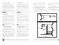
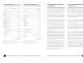
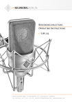
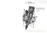
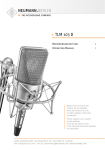
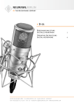
Bedienungsanleitung
Operating Instructions
Ollenhauerstr. 98
D-13403 Berlin
Tel.: +49-30 / 41 77 24-0
Fax: +49-30 / 41 77 24-50
Email: [email protected]
Web: www.neumann.com
TLM 103
Inhaltsverzeichnis
Table of Contents
1.
Kurzbeschreibung
1.
A Short Description
2.
Das Kondensatormikrophon TLM 103
2.
The TLM 103 Condenser Microphone
2.1 Ausführungsformen und Beschaltung des
Ausganges
2.1 Microphone Versions
and Output Wiring
2.2 Mikrophonkabel
2.2 Microphone Cables
3.
3.
Stromversorgung
Power Supply
3.1 Phantomspeisung
3.1 Phantom Powering
3.2 Betrieb mit Netzgeräten
3.2 ac Supply Operation
3.3 Batteriespeisung
3.3 Battery Powering
3.4 Betrieb an unsymmetrischen oder
mittengeerdeten Eingängen
3.4 Operation with Unbalanced or Center
Tap Grounded Inputs
4.
Technische Daten TLM 103
4.
5.
Einige Hinweise zur Pflege von Mikrophonen
5.
Some Remarks on Maintenance
6.
Frequenzgang und Polardiagramm
6.
Frequency Response and Polar Pattern
7.
Zubehör
7.
Accessories
TLM 103 Technical Specifications
2. Das Kondensatormikrophon
TLM 103
2. The TLM 103 Condenser
Microphone
Das Kondensatormikrophon TLM 103 ist ein Studiomikrophon der Serie fet 100 mit der Richtcharakteristik Niere.
The TLM 103 condenser microphone is a studio microphone of the fet 100 series with a cardioid polar
pattern.
Die Buchstaben TLM stehen für Transformatorloses
Mikrophon.
The letters TLM stand for Transformerless Microphone.
Der zur Leistungsanpassung der Mikrophonausgangsspannung an die Betriebsspannung üblicherweise verwendete Übertrager ist im TLM 103 durch eine elektronische Schaltung ersetzt, die – wie ein Übertrager
– für eine gute Unsymmetriedämpfung sorgt. Daher
werden Störsignale, die auf die symmetrische Modulationsleitung einwirken, wie gewohnt unterdrückt.
The transformer which used to couple a microphone’s output to the supply voltage, was replaced in
the TLM 103 by an electronic circuit which, like a
transformer, maintains the excellent common mode
rejection (CMR). Interference induced in the balanced
modulation line is therefore suppressed as usual.
Die Eigenstörspannung des TLM 103 konnte gegenüber vergleichbaren Mikrophontypen stark gesenkt
werden, wobei das Mikrophon Schalldruckpegel von
138 dB unverzerrt überträgt und einen Dynamikumfang von 131 dB zur Verfügung stellt (nach DIN/IEC
651).
The self-noise level of the TLM 103 is much lower
than that of comparable microphone models while its
overload capability extends to 138 dB SPL, providing
a dynamic range of 131 dB (DIN/IEC 651).
Das TLM 103 wird von der Vorderseite besprochen,
die durch das Neumann-Logo gekennzeichnet ist.
The TLM 103 is addressed from the front, marked
with the Neumann logo.
Die im Drahtgeflechtkorb des Mikrophons befindliche
Großmembrankapsel K 103 besitzt einen bis ca. 5 kHz
ebenen Frequenzgang und im darüberliegenden Frequenzbereich eine breite, flache Präsenzanhebung von
4 dB. Die Kapsel basiert auf der des Mikrophons
U 87, indem deren Elektrode und Membran Verwendung finden.
Its grille houses the large diaphragm K 103 capsule. It
has a linear frequency response up to some 5 kHz
with a wide flat presence boost of 4 dB at the top
end. The capsule is based on that of the U 87 microphone and and uses their back electrode and diaphragm.
No resonance effects are used to obtain the characteristics mentioned above. As a consequence, the microphone features excellent transient behavior and
transmits all transient phenomena of music or voice
without distortion.
1. Kurzbeschreibung
1. A Short Description
Das Kondensatormikrophon TLM 103 ist ein Studiomikrophon mit der Richtcharakteristik Niere.
The TLM 103 is a studio condenser microphone with
cardioid polar pattern.
Es zeichnet sich aus durch extrem niedriges Eigengeräusch und höchste Aussteuerbarkeit, transformatorlose Schaltungstechnik, besonders saubere, freie und
verfärbungsfreie Klangübertragung.
Its most important features are extraordinarily low self
noise level combined with highest output capability,
transformerless circuit, extraordinarily true sound transduction, free of coloration.
Das Mikrophon hat einen symmetrischen, übertragerlosen Ausgang. Der 3-polige XLR-Steckverbinder hat
folgende Belegung:
The microphone has a balanced, transformerless output. The 3-pin XLR connector has the following pin
assignments:
Da zum Erreichen der genannten Mikrophoneigenschaften keine Resonanzwirkungen genutzt werden, ist das
Impulsverhalten des Mikrophons ausgezeichnet, und
es vermag alle Ausgleichsvorgänge in Musik und Sprache unverfälscht zu übertragen.
Stift 1:
0 V/Masse
Pin 1:
0 V/ground
Die Kapsel ist zum Schutz gegen Körperschallübertragung elastisch gelagert.
In order to protect the capsule from mechanical shock
transmission it is elastically suspended.
Stift 2:
Modulation (+Phase)
Pin 2:
Modulation (+phase),
Stift 3:
Modulation (-Phase).
Pin 3:
Modulation (-phase).
Da der Verstärker des TLM 103 bis unter 20 Hz linear verläuft, können auch extrem niederfrequente Signale unverfälscht übertragen werden.
As the TLM 103‘s amplifier is linear also below 20 Hz,
extremely low frequency signals can be transmitted
without distortion as well.
Andererseits ist das Mikrophon dadurch empfindlicher
für tieffrequente Störungen wie Körperschall oder Popund Windgeräusche. Daher empfiehlt sich eventuell
die Verwendung der elastischen Aufhängung EA 1 (mt),
des Popschirms PS 10 oder PS 20 oder des Windschutzes WS 87.
On the other hand the microphone is therefore more
sensitive to low-frequency noises like structure-borne
or wind and pop disturbances. For specific applications
it is therefore recommended to use protective accessories as the EA 1 (mt) elastic suspension, the PS 10
or PS 20 pop screens or the WS 87 windscreen.
Feldübertragungsfaktor 21 mV/Pa = – 34 dB re. 1V/Pa.
Das Mikrophon wird mit 48 V, 3 mA phantomgespeist
(DIN 45 596 bzw. IEC 268-15).
The output sensitivity is 21 mV/Pa = – 34 dB re. 1V/Pa.
The microphone is phantom powered from 48 V,
3 mA (IEC 268-15/DIN 45596).
Das TLM 103 wird von der Vorderseite besprochen,
die durch das Neumann-Logo gekennzeichnet ist.
The TLM 103 is addressed from the front, marked
with the Neumann logo.
Das Mikrophon wird in einem Holzetui zusammen mit
dem Stativgelenk SG 1 geliefert.
The microphone comes in a wooden case including
the SG 1 swivel mount.
2
3
2.1 Ausführungsformen und Beschaltung
des Ausganges
2.1 Microphone Versions and Output Wiring
TLM 103 .............................. ni ............................... Best.-Nr. 08430
Das Mikrophon TLM 103 besitzt eine nickelmatte
Oberfläche und ist mit einem 3-poligen XLR-Steckverbinder ausgerüstet. Die Zuordnung der Mikrophonanschlüsse entspricht DIN 45 599, Kennzeichen I bzw.
IEC 268-12 (pin. conn. 130-x-IEC 02):
TLM 103 .............................. ni ................................ Cat. No. 08430
The TLM 103 microphone has a matt satin finish and
is equipped with a 3-pole XLR connector. The microphone is wired per IEC 268-12 (pin conn. 130-xIEC 02) or DIN 45 599 I, respectively:
Die Modulationsadern liegen an Stift 2 und 3, die Abschirmung an Stift 1.
Modulation is connected to pins 2 and 3, the shield
to pin 1.
Bei einem Schalldruckanstieg vor der Mikrophonmembran tritt an Stift 2 eine positive Spannung auf.
A sudden sound pressure rise in front of the diaphragm
causes a positive voltage to appear at pin 2.
TLM 103 mt ...................... sw ............................. Best.-Nr. 08431
Wie oben, jedoch schwarzmatte Oberfläche.
TLM 103 mt ...................... blk .............................. Cat. No. 08431
As above, but with matt black finish.
2.2 Mikrophonkabel
2.2 Microphone Cables
Die akustischen Eigenschaften der Mikrophone werden auch durch sehr lange (Neumann-) Kabel nicht
beeinflußt. Erst bei Kabellängen deutlich über 300 m
macht sich ein Abfall im oberen Frequenzbereich bemerkbar.
The electroacoustic properties of the microphones are
not affected even by very long (Neumann) cables.
However, if cables are well over 300 m, a fall-off in
the upper frequency range becomes apparent.
Neumann bietet ein vielfältiges Kabelsortiment an, von
dem hier ein Ausschnitt erwähnt wird. Andere als
die genannten Kabellängen sowie Kabelmaterial ohne
Armaturen sind auf Wunsch lieferbar.
Neumann offers a wide range of cables. Only a selection is presented here. Other cable lengths or cable
materials without connectors are available on request.
Für das Mikrophon TLM 103 stehen folgende Kabel
zur Verfügung:
The following cables are available for the TLM 103
microphone:
IC 3 mt ................................. sw ............................. Best.-Nr. 06543
10 m langes Mikrophonkabel, Durchmesser 5 mm, mit
Doppeldrallumspinnung als Abschirmung. Schwarzmatte 3-polige XLR-Steckverbinder. Führt am Ausgang
des Netzgerätes die Modulation weiter.
IC 3 mt ................................. blk .............................. Cat. No. 06543
10 m long microphone cable, 5 mm in diameter, with
double twist (double helix) braiding as shield. Threepin XLR connectors, matt black. For feeding the audio signal to mixing consoles, etc.
IC 31 mt (5 m) ............... sw ............................. Best.-Nr. 06570
5 m langes Mikrophonkabel, Durchmesser 4,5 mm, mit
Doppeldrallumspinnung als Abschirmung. Schwarzmatte 3-polige XLR-Steckverbinder. Zur Vermeidung von
Reibgeräuschen bei der Verwendung an der Angel
oder an Kunststoffdurchführungen (z.B. bei Windschutzkörben) ist das Kabel textilumsponnen.
IC 31 mt (5 m) ............... blk .............................. Cat. No. 06570
5 m long microphone cable, 4.5 mm in diameter, with
double twist braiding for screening. 3-pin XLR connectors, matte black. This cable is textile-braided to
avoid frictional noise due to the handling of booms or
plastic leadings (for example in windscreens).
IC 4 (10 m) ....................... ni ............................... Best.-Nr. 06547
IC 4 mt (10 m) ............... sw ............................. Best.-Nr. 06557
10 m langes Mikrophonkabel für Mikrophone mit Gewindeanschluß, Durchmesser 5 mm, mit Doppeldrallumspinnung als Abschirmung. Dreh- und schwenkbares Stativgelenk SGCD 3 (mt), 3-polige XLR-Steckverbinder, der Gewindeanschluß hat 5/8"-27-Gang. Ein
Adapter für 1/2"- und 3/8"-Gewindezapfen wird mitgeliefert.
IC 4 (10 m) ....................... ni ................................ Cat. No. 06547
IC 4 mt (10 m) ............... blk .............................. Cat. No. 06557
10 m long microphone cable, 5 mm in diameter, with
double twist braiding for screening. 3-pin XLR connectors and SGCD 3 rotatable swivel mount. It has a
5/8"-27 female thread that can be fastened to tripods.
A threaded adapter for 1/2"- and 3/8" studs is included. Designed for microphones with a thread.
4
AC 22 (0,3 m) ....................................................... Best.-Nr. 06598
Adapterkabel mit einer 5-poligen XLR-Buchse und einem 3,5 mm Stereoklinkenstecker, unsymmetrisch, für
den Anschluß des 5-poligen XLR-Ausganges des Speisegerätes BS 48 i-2 oder der Matrixbox MTX 191 A
an Geräte mit 3,5 mm Stereoklinkenbuchse. Vorgesehen für alle Mikrophone der Serien fet 80/100 und
KM 100 F mit Ausnahme der Ausgangsstufe KM 100
und des GFM 132.
AC 22 (0.3 m) ........................................................ Cat. No. 06598
Adapter cable with a 5-pin XLR connector on one
end and an unbalanced 3.5 mm stereo jack on the
other end. It is used to connect the 5-pin XLR output of the BS 48 i-2 power supply or the MTX 191 A
matrix amplifier to units with a 3.5 mm stereo input.
It is designed for all microphones of the fet 80/100
series and KM 100 F, excluding the KM 100 and the
GFM 132.
AC 25 (0,3 m) ....................................................... Best.-Nr. 06600
Adapterkabel mit einer 3-poligen XLR-Buchse und einem 6,3 mm Monoklinkenstecker, unsymmetrisch, für
den Anschluß des 3-poligen XLR-Ausganges eines
Speisegerätes BS 48 i oder N 48 i-2 an Geräte mit
6,3 mm Monoklinkenbuchse. Vorgesehen für alle
fet 80/100-Mikrophone und KM 100 F mit Ausnahme
der Ausgangsstufe KM 100 und des GFM 132.
AC 25 (0.3 m) ........................................................ Cat. No. 06600
Adapter cable with 3-pin XLR connector and a 6.3 mm
monojack, unbalanced. It is used to connect 3-pin XLR
outputs of the BS 48 i or N 48 i-2 power supplies to
units with a 6.3 mm monojack input. Designed for all
microphones of the fet 80/100 series and
KM 100 F, excluding the KM 100 output stage and
the GFM 132 boundary-layer microphone.
AC 27 (0,3 m) ....................................................... Best.-Nr. 06602
Y-Kabel mit einer 5-poligen XLR-Buchse und zwei
6,3 mm Monoklinkensteckern, unsymmetrisch, für den
Anschluß des 5-poligen XLR-Ausganges eines Speisegerätes BS 48 i-2 oder der Matrixbox MTX 191 A
an Geräte mit 6,3 mm Monoklinkenbuchsen. Vorgesehen für alle fet 80/100-Mikrophone und KM 100 F
mit Ausnahme von KM 100 und GFM 132.
AC 27 (0.3 m) ........................................................ Cat. No. 06602
Y-cable with a 5-pin XLR connector and two 6.3 mm
monojacks, unbalanced. It is used to connect 5-pin
XLR outputs of the BS 48 i-2 power supply or the
MTX 191 A matrix amplifier to units with 6.3 mm
monojack inputs. Designed for all microphones of the
fet 80/100 series and KM 100 F, excluding the KM 100
and the GFM 132.
3. Stromversorgung
3. Power Supply
3.1 Phantomspeisung
3.1 Phantom Powering
Die Mikrophone der Serie fet 100 werden mit 48 V
phantomgespeist (P48, IEC 1938).
The fet 100 series microphones are phantom-powered at 48 V (P48, IEC 1938).
Bei der Phantomspeisung fließt der Speisestrom vom
positiven Pol der Spannungsquelle über die elektrische Mitte der beiden Modulationsadern zum Mikrophon. Er wird hierzu über zwei gleich große Widerstände beiden Tonadern gleichsinnig zugeführt. Die
Rückleitung des Gleichstroms erfolgt über den Kabelschirm. Zwischen beiden Modulationsadern besteht
also keine Potentialdifferenz. Daher ist mit der Phantomspeisung eine kompatible Anschlußtechnik möglich: Auf die Anschlußdosen können wahlweise auch
dynamische Mikrophone oder Bändchenmikrophone
sowie die Modulationskabel röhrenbestückter Kondensatormikrophone geschaltet werden, ohne daß die
Speisegleichspannung abgeschaltet werden muß.
With phantom powering the dc from the positive supply terminal is divided via two identical resistors, one
half of the dc flowing through each audio (modulation) conductor to the microphone, and returning to
the voltage source via the cable shield.Phantom powering provides a fully compatible connecting system,
since no potential differences exist between the two
audio conductors. Studio outlets so powered will therefore also accept dynamic microphones and ribbon microphones as well as the modulation conductors of
tube-equipped condenser microphones without the
need to switch off the dc supply voltage.
No harm is done even if a phantom power supply is
connected to an outlet which is phantom powered
from another source.
Der Ausgang eines Phantomspeisegerätes darf auch
auf bereits anderweitig phantomgespeiste Mikrophoneingänge gesteckt werden.
5
3.2 Betrieb mit Netzgeräten
3.2 ac Supply Operation
Für die Stromversorgung des TLM 103 sind prinzipiell alle P48-Netzgeräte entsprechend IEC 1938 geeignet, die mindestens 3 mA je Kanal abgeben.
All P48 power supplies according to IEC 1938, providing at least 3 mA per channel, are suitable in principle for powering the TLM 103 microphone.
Das Neumann P48-Netzgerät hat die Bezeichnung
N 48 i-2. Es ist zur Stromversorgung zweier MonoKondensatormikrophone oder eines Stereomikrophons
mit 48 V ± 1 V, maximal 2 x 5 mA, geeignet (siehe
auch Neumann-Druckschrift 68832: „48 V-Phantomspeisegeräte“).
The Neumann P48 power supply unit bears the designation N 48 i-2. It is designed to power two mono
condenser microphones or one stereo microphone at
48 V ± 1 V, max. 2 x 5 mA. (See also Neumann
bulletin No. 68832: “Phantom 48 Vdc Power Supplies”).
Die Zuordnung der Mikrophonanschlüsse und die Polarität der Modulationsadern ist am Ausgang der Speisegeräte die gleiche wie am Mikrophon.
Audio signal polarity at the power supply units is identical with that at the microphone.
N 48 i-2 (230 V) ........... sw ............................. Best.-Nr. 06500
N 48 i-2 (117 V) ........... sw ............................. Best.-Nr. 06502
N 48 i-2 (230V) ............. blk .............................. Cat. No. 06500
N 48 i-2 (117V) ............. blk .............................. Cat. No. 06502
3.3 Batteriespeisung
3.3 Battery Powering
Steht keine Netzspannung zur Verfügung, kann die Speisung mit einem der Geräte BS 48 i (für ein Mikrophon) oder BS 48 i-2 (für zwei Mikrophone) erfolgen.
If a mains power source is not available, power can
be supplied by one of the units BS 48 i (for one microphone) or BS 48 i-2 (for two microphones).
Beide Geräte liefern 48 V ± 1 V, maximal je 5 mA,
und werden jeweils von einer 9 Volt-Blockbatterie Typ
IEC 6 F 22 gespeist.
Both units supply 48 V ± 1 V, at 5 mA maximum,
and are powered by a 9-volt monobloc battery Type
IEC 6 F 22.
Ein Mikrophon der Serie fet 100 kann mit einem
BS 48 i ca. 20 Stunden betrieben werden (siehe auch
Neumann-Druckschrift 68832: „48 V-Phantomspeisegeräte“).
A microphone of the fet 100 series can be operated
for approx. 20 hours on a BS 48 i. See Neumann
bulletin 68832: “Phantom 48 Vdc Power Supplies”.
Die Zuordnung der Mikrophonanschlüsse und die Polarität der Modulationsadern ist am Ausgang der Speisegeräte die gleiche wie am Mikrophon.
Modulation polarity at the power supply is identical
with that at the microphone.
BS 48 i (für ein Mikrophon) ......................... Best.-Nr. 06494
BS 48 i-2 (für zwei Mikrophone) ............... Best.-Nr. 06496
BS 48 i (for one microphone) ....................... Cat. No. 06494
BS 48 ii-2
-2 (for two microphones) ................ Cat. No. 06496
3.4 Betrieb an unsymmetrischen oder
mittengeerdeten Eingängen
3.4 Operation with Unbalanced or Center
Tap Grounded Inputs
Die 48 V-Phantomspeisegeräte BS 48 i, BS 48 i-2 und
N 48 i-2 haben gleichspannungsfreie Ausgänge, so daß
für den Anschluß an einen unsymmetrischen Eingang
kein Übertrager erforderlich ist.
The 48 V phantom powering units BS 48 i, BS 48 i-2
and N 48 i-2 have dc-free outputs, so that no transformer is required for connecting to an unbalanced
input.
Beim TLM 103 ist Pin 2 die heiße Phase, und Pin 3
muß für unsymmetrische Eingänge an Masse gelegt
werden (siehe Abbildung 1).
In the case of the TLM 103 condenser microphone
pin 2 is the hot phase, and pin 3 must be connected
to earth (see Fig. 1).
Bei vielen anderen als den o.g. Phantomspeisegeräten liegen nicht nur die Modulationsleitungen zum Mikrophon auf dem Potential der Speisespannung von
+ 48 V, sondern auch die vom Speisegerät abgehenden Modulationsleitungen. Für die in der Studiotechnik allgemein üblichen symmetrischen und erdfreien
Verstärker- und Mischpulteingänge ist dies ohne Bedeutung.
In the case of many other phantom powering units
(except those mentioned above), not only the modulation leads to the microphone, but also the outgoing
modulation leads from the powering unit, are at the
potential of the feed voltage (+ 48 V). This is of no
significance for the balanced, floating amplifier and mixing console inputs in general studio use.
6
Dagegen wird die Speisespannung beim Anschluß an
unsymmetrische oder mittengeerdete Verstärkereingänge kurzgeschlossen, und es ist kein Betrieb möglich.
On the other hand, the feed voltage will be shortcircuited when connected to unbalanced or center tap
grounded amplifier inputs, and no operation will be
possible.
Dann bestehen folgende Lösungsmöglichkeiten:
This can be circumvented as follows:
a) In mittengeerdeten Geräten mit Eingangsübertrager (z.B. einige NAGRA-Geräte) kann die betreffende Erdverbindung fast immer ohne Nachteile für die
Funktion des Gerätes aufgetrennt werden.
a) In center tap grounded equipment with input
transformer (e.g. some NAGRA units), the earth lead
can almost always be disconnected without affecting
the function of the equipment.
b) In jede abgehende Modulationsleitung kann zur
Abblockung der 48 V-Gleichspannung eine RC-Kombination eingefügt werden (siehe Abbildung 2 und
Neumann-Information Nr. 84 221).
b) In every outgoing modulation lead, an RC network can be incorporated to block the 48 Vdc voltage
(See Fig. 2 and Neumann-Information no. 84 222).
Abbildung / Figure 1
Abbildung / Figure 2
7
4. Technische Daten
4. Technical Specifications
Akust. Arbeitsweise ........... Druckgradientenempfänger
Acoustical operating principle ............. Pressure gradient
transducer
Richtcharakteristk .................................................................. Niere
Polar pattern ....................................................................... cardioid
Übertragungsbereich ....................................... 20 Hz...20 kHz
Frequency range ................................................ 20 Hz...20 kHz
Feldübertragungsfaktor1) ...................................... 21 mV/Pa = – 33,5 dBV ± 1 dB
Sensitivity
Nennimpedanz ............................................................... 50 Ohm
Rated impedance ......................................................... 50 ohms
Nennabschlußimpedanz ...................................... 1000 Ohm
Rated load impedance .......................................... 1000 ohms
Geräuschpegelabstand
(CCIR 468-3) ..................................................................... 76,5 dB
S/N ratio
CCIR 468-3 ......................................................................... 76.5 dB
Geräuschpegelabstand
(DIN/IEC 651 .......................................................................... 87 dB
S/N ratio
DIN/IEC 651 ........................................................................... 87 dB
Ersatzgeräuschpegel
(CCIR 468-3) ..................................................................... 17,5 dB
Equivalent SPL
CCIR 468-3 ......................................................................... 17.5 dB
Ersatzgeräuschpegel
(DIN/IEC 651) .................................................................... 7 dB-A
Equivalent SPL
IEC/DIN 651 ........................................................................ 7 dB-A
Grenzschalldruckpegel für
0,5 % Klirrfaktor2) .............................................................. 138 dB
Max. SPL for 0.5 % THD2) ......................................... 138 dB
Max. Ausgangsspannung dabei ............................... 13 dBu
Max. output voltage ........................................................ 13 dBu
Speisespannung 3) .................................................................. 48
V±4V
Supply voltage3) ....................................................................... 48 V ± 4 V
Stromaufnahme3) ..................................................................................... 3 mA
Current consumption3) ................................................................. 3 mA
Gewicht ...................................................................................... 500 g
Weight ............................................................... 500 g (17.7 ozs.)
Durchmesser ..................................................................... 60 mm
Diameter ................................................................................ 60 mm
Länge ..................................................................................... 132 mm
Length .................................................................................. 132 mm
1 Pa = 10 µbar
0 dB = 20 µPa
1 Pa = 10 µbar
0 dB = 20 µPa
1) bei 1 kHz an 1 kOhm Nennabschlußimpedanz.
1 Pa = 94 dB SPL.
1)
2)
Klirrfaktor des Mikrophonverstärkers bei einer Eingangsspannung, die der
von der Kapsel beim entsprechenden Schalldruck abgegebenen Spannung
entspricht.
2)
3)
3)
1) ....................... 21
mV/Pa = – 33,5 dBV ± 1 dB
at 1 kHz into 1 kOhm rated load impedance.
1 Pa = 94 dB SPL.
THD of microphone amplifier at an input voltage equivalent to the
capsule output at the specified SPL.
Phantomspeisung (P48, IEC 1938).
8
Phantom powering (P48, IEC 1938).
5. Einige Hinweise zur Pflege von
Mikrophonen
5. Some Remarks on Microphone
Maintenance
Staubschutz verwenden: Mikrophone, die nicht im Einsatz sind, sollte man nicht auf dem Stativ einstauben
lassen. Mit einem Staubschutzbeutel (nicht fusselnd)
wird dies verhindert. Wird ein Mikrophon längere Zeit
nicht verwendet, sollte es in einem Schrank bei normalem Umgebungsklima aufbewahrt werden.
Use the dust cover: Microphones not in operation
should not be left on the floor stand unprotected. With
a non-fluffy dust cover the microphone can be protected from dust settling on the capsule. When not
in use for a longer spell, the microphone should be
stored in a closet at standard climatic conditions.
Popschutz verwenden: Ein Popschutz hat nicht nur die
Aufgabe, bei Gesangsaufnahmen die Entstehung von
Poplauten zu verhindern. Er vermeidet auch effizient,
daß sich von der Feuchtigkeit des Atems bis hin zu Essensresten unerwünschte Partikel auf der Membran ablagern.
Use a pop screen: The pop screen not only eliminates
the plosive pop noises in vocal recordings. In closemiked vocal applications it also efficiently protects the
diaphragm from almost anything, including breath humidity down to food particles.
Keine überalterten Windschutze verwenden: Auch
Schaumstoff altert. Das Material kann brüchig und krümelig werden. Anstatt das Mikrophon zu schützen, kann
er dann zur Verunreinigung der Mikrophonkapsel führen. Überalterte Windschutze also bitte entsorgen.
Do not use overaged wind shields: Even the foam material of wind shields ages. With very old wind shields,
the material decays and becomes brittle. The particles
can then settle on the diaphragm. So, please dispose
of overaged wind shields.
Funktionstest: Moderne Kondensatormikrophone nehmen durch lautes Ansprechen keinen Schaden. Zur
Kontrolle, ob ein solches Mikrophon angeschlossen ist,
sollte man es aber keinesfalls anpusten oder anpoppen, da dies einem akustischen Signal von mehr als
140 dB (!) entsprechen kann. Normale Sprache genügt
zum Funktionstest völlig.
Function testing: Modern condenser microphones cannot be harmed by very high sound pressure levels. Still,
there is no need for pop-testing to see if a microphone
is working and pulled up on the console. Normal speech
is good enough, and pop-testing can produce sound
pressure levels exceeding 140 dB!
Selbsthilfe kann teuer sein! Leider kommt es doch vor,
daß durch eine Selbstreparatur mehr beschädigt als
behoben wird. Insbesondere das Reinigen verschmutzter Kapseln erfordert viel Erfahrung und die Hand eines Fachmanns. Der Lackschutz auf Platinen zeigt u.a.
an, daß dort nicht gelötet werden darf. Einige Bauteile
sind speziell selektiert und können nicht durch Material
von der Stange ersetzt werden. Um unnötige Kosten
zu vermeiden, empfiehlt sich die Einsendung an unsere
Vertretungen oder an uns.
Do-it-yourself can be expensive: Do-it-yourself repairs
can sometimes be more harmful than beneficial. Especially cleaning soiled capsules does take a skilled hand
and quite some experience. Furthermore, the protective lacquer shows the parts of the printed circuit boards
where e.g. soldering should be avoided. Other parts
may be specifically selected and cannot be replaced by
standard components. To avoid unnecessary cost, we
recommend sending in defective microphones to our
distributors, or to us directly, for servicing.
Inspektion durchführen lassen: Regelmäßiges Durchchekken des Mikrophonbestands, wie es einige Schauspielhäuser und Rundfunkanstalten praktizieren, kann bei der
Früherkennung von Schäden helfen. Leichte Verschmutzungen lassen sich eher beseitigen, als eine untrennbar
in die Membran eingebrannte Nikotinschicht. Insbesondere bei Mikrophonen im Verleih und in verunreinigenden Umgebungen empfiehlt sich die regelmäßige Kontrolle, deren Kosten im Vergleich zu einer
aufwendigen Reparatur sehr gering sind.
Regular servicing: As some theaters and broadcasters
do on a regular basis, sending in microphones for servicing can help in early recognition of damages. Slight
soiling can be removed much easier than some nicotine layer firmly embedded in the diaphragm. Especially with microphones on loan and in dustier / smokier environments regular checking proves beneficial,
as the cost is rather small compared to a major overhaul.
9
6. Frequenzgang und Polardiagramm
Frequency Response and Polar Pattern
gemessen im freien Schallfeld nach IEC 60268-4
measured in free-field conditions (IEC 60268-4)
10
7. Zubehör
7. Accessories
Weitere Artikel sind im Katalog „Zubehör“ beschrieben.
Further articles are described in the catalog “Accessories”.
7.1 Stativgelenke und mechanische Adapter
7.1 Stand Mounts and Mechanical Adapter
DS 120 .................................. sw ............................. Best.-Nr. 07343
Das DS 120 hat eine 150 mm lange Schiene, die zwei
verschiebbare 1/2"-Gewindeschrauben zur Befestigung
zweier Mikrophone in ihren Halterungen enthält. Hierbei sind Abstand und Winkel für die Anordnung der
Mikrophone wählbar. Der Gewindeanschluß hat 5/8"27-Gang. Ein Reduzierstück zur Verbindung mit 1/2"und 3/8"-Gewindezapfen wird mitgeliefert.
DS 120 .................................. blk .............................. Cat. No. 07343
The DS 120 has a 150 mm long support bar with two
movable 1/2" threaded studs. Two microphones in
their mounts can be attached. Any space or angle between the microphones is freely adjustable within the
given limits. It has a 5/8"-27 female thread. A threaded adapter for the connection to 1/2" and 3/8" studs
is included.
SG 1 ......................................... sw ............................. Best.-Nr. 08445
Das Stativgelenk SG 1 kann an das Bodenstück der
Mikrophone TLM 103, TLM 193 und M 147 Tube geschraubt werden und dient zur Befestigung dieser Mikrophone auf einem Stativ. Die Halterung des SG 1
ist aus Metall, der Gewindeanschluß hat 5/8"-27-Gang.
Ein Reduzierstück zur Verbindung mit 1/2"- und 3/8"Gewindezapfen wird mitgeliefert.
SG 1 ......................................... ni ................................ Cat. No. 08445
The SG 1 swivel mount screws to the bottom part
of the TLM 103, TLM 193 and M 147 Tube microphones, which then can be mounted to microphone
stands. The microphone mount of the SG 1 is made
of metal. The swivel mount has a 5/8"-27 thread, and
a thread adapter for connecting to 1/2" and 3/8" studs.
7.2 Tisch- und Fußbodenständer
7.2 Table and Floor Stands
MF 3 ........................................ sw ............................. Best.-Nr. 07321
Der Mikrophonfuß MF 3 ist ein Tischständer mit Eisenfuß, 1,6 kg schwer, Durchmesser 110 mm. Der Ständer
ist schwarzmatt lackiert und steht gleitfest auf einer Moosgummischeibe. Ein umwendbarer Gewindezapfen und ein
mitgeliefertes Reduzierstück ermöglichen die Verwendung
für 1/2"- und 3/8"-Gewindeanschlüsse.
MF 3 ........................................ blk .............................. Cat. No. 07321
Table stand with iron base, 1.6 kg, 110 mm in diameter. The table stand has a matte black finish and rests
on a nonskid rubber disk attached to the bottom. A
reversible stud and a reducer for 1/2" and 3/8" threads
are also supplied.
MF 4 ....................................... sw .............................. Best.-Nr. 07339
Der Mikrophonfuß MF 4 ist ein Fußbodenständer aus
Grauguß, ca. 2,6 kg schwer, Durchmesser 160 mm. Der
Ständer ist schwarzmatt lackiert und steht gleitfest auf einem Gummiring. Ein umwendbarer Gewindezapfen und
ein mitgeliefertes Reduzierstück ermöglichen die Verwendung für 1/2"- und 3/8"-Gewindeanschlüsse.
MF 4 ....................................... blk .............................. Cat. No. 07339
Floor stand with grey cast iron base, 2.6 kg, 160 mm in
diameter. The floor stand has a matte black finish and
rests on a nonskid rubber disk attached to the bottom.
A reversible stud and a reducer for 1/2" and 3/8" threads
are also supplied.
7.3 Stativverlängerungen
7.3 Stand Extensions
Die Stativverlängerungen STV... werden zwischen Fußbodenständer und Mikrophonhalterung geschraubt. Dadurch entstehen unterschiedlich hohe Tisch- oder Fußbodenstative.
The STV... stand extensions are used between microphone and floor stands to provide table or floor
stands of variable heights.
11
Die STV... haben eine Länge von 40, 200, 400 oder
600 mm. Durchmesser: 19 mm.
The STVs are 40, 200, 400 or 600 mm long.
Diameter: 19 mm.
STV 4 ...................................... sw ............................. Best.-Nr.
STV 20 ................................... sw ............................. Best.-Nr.
STV 40 ................................... sw ............................. Best.-Nr.
STV 60 ................................... sw ............................. Best.-Nr.
STV 4 ...................................... blk .............................. Cat.
STV 20 ................................... blk .............................. Cat.
STV 40 ................................... blk .............................. Cat.
STV 60 ................................... blk .............................. Cat.
06190
06187
06188
06189
No.
No.
No.
No.
06190
06187
06188
06189
7.4 Elastische Aufhängung
7.4 Elastic Suspension
Um mechanische Erschütterung fernzuhalten, empfiehlt sich die Verwendung einer elastischen Mikrophonaufhängung.
The use of an elastic suspension is recommended to
prevent the microphone from being exposed to strong
mechanical vibrations caused by structure borne shock
waves.
EA 1 ........................................ ni ............................... Best.-Nr. 08449
EA 1 mt ............................... sw ............................. Best.-Nr. 08450
Die EA 1 ist für die Mikrophone TLM 103, TLM 193
und M 147 Tube vorgesehen. Der schwenkbare Gewindeanschluß zur Befestigung auf Stativen hat 5/8"27-Gang. Ein Reduzierstück zur Verbindung mit 1/2"und 3/8"-Gewindezapfen wird mitgeliefert.
7.7 Schaumstoffwindschutz
7.7 Foam Windscreen
WS 87 .................................... sw ............................. Best.-Nr. 06753
Durchmesser ca. 90 mm. Dämpfung des Windgeräusches ca. 26 dB. Dämpfung bei 15 kHz ca. 3 dB. Farbe schwarz.
WS 87 .................................... blk .............................. Cat. No. 06753
Diameter is approx. 90 mm. Suppression of wind noise
approx. 26 dB. Attenuation at 15 kHz approx. 3 dB.
Color black.
Zum Vermeiden von Störgeräuschen, die bei Nahbesprechung, Windeinfluß oder z.B bei schnellem Schwenken des Mikrophongalgens auftreten können, sind Windschutzeinrichtungen aus offenporigem Polyurethanschaum lieferbar. Diese Windschutzeinrichtungen erzeugen keine störenden Resonanzen und beeinflussen den
Frequenzgang des Übertragungsmaßes nur geringfügig.
Open-cell polyurethane foam windscreens are available to guard against disturbances that may be caused
by wind, close-talking applications, or rapid boom movements. These windscreens have no disturbing resonances and only slightly affect the frequency response.
EA 1 ........................................ ni ................................ Cat. No. 08449
EA 1 mt ............................... blk .............................. Cat. No. 08450
The EA 1 is designed for the TLM 103, TLM 193 and
M 147 Tube microphones. It has a swivel mount with
a 5/8"-27 female thread that can be fastened to tripods. Included is a threaded adapter to connect to
1/2"- and 3/8" studs.
7.5 Popschutz
7.5 Popscreen
PS 10 ...................................... sw ............................. Best.-Nr. 07345
Der Popschirm PS 10 bietet einen sehr wirksamen
Schutz vor den sogenannten Popgeräuschen. Er bestehen aus einem runden dünnen Holzrahmen, der beidseitig mit schwarzer Gaze bespannt ist. Der PS 10 hat
10 cm Durchmesser.
PS 10 ...................................... blk .............................. Cat. No. 07345
The PS 10 popshield provides excellent suppression
of so-called pop noise. It consists of a round, thin
wooden frame covered with black gauze on both sides.
The PS 10 is 10 cm in diameter.
Der um ca. 230° schwenkbare Stativanschlußstutzen
hat 5/8"-27-Gang-Innengewinde mit einem Reduzierstück
zur Verbindung mit 1/2"- und 3/8"-Gewindezapfen.
The stand adaptor with 5/8"-27 female thread can be
altered by 230°. A reducer for connection to 1/2" and
3/8" studs is included.
Zum Lieferumfang gehört ein zweiseitig konterbarer
Gewindezapfen, um einen Popschirm z.B. an die Klammer MKV zu schrauben. Damit kann er an die Stativstangen oder an die Steckverbinder geklammert werden.
For mounting a popshield to the MKV quick-release
clamp, a double-sided stud with locknut is included
in the supply schedule. Used in conjunction with the
MKV quick-release clamp the popshields can be attached to stands or connectors.
PS 20 ...................................... sw ............................. Best.-Nr. 07346
Wie oben, jedoch 20 cm Durchmesser.
PS 20 ...................................... blk .............................. Cat. No. 07346
As above, but 20 cm in diameter.
7.6 Mikrophon-Neigevorrichtung
7.6 Auditorium Hanger
MNV 87 ............................... ni ............................... Best.-Nr. 06804
MNV 87 mt ....................... sw ............................. Best.-Nr. 06806
Die Mikrophonneigevorrichtung MNV 87 besteht aus
einer Kabelhalterung und einem 1/2"-Gewindezapfen.
Sie wird in das Stativgelenk des Kabels IC 4 geschraubt
(s. Kapitel 2.3) und ermöglicht dann die Einstellung
der Mikrophonneigung bei frei am Kabel hängendem
Mikrophon.
MNV 87 ............................... ni ................................ Cat. No. 06804
MNV 87 mt ....................... blk .............................. Cat. No. 06806
The MNV 87 auditorium hanger consists of a cable
clamp and a 1/2" stud with which it is screwed into
the swivel mount of the IC 4 cable (see chapter 2.3).
The microphone can then be tilted as needed because it is freely suspended from its own cable.
12
13
IC 3 mt
IC 31 mt
IC 4 (mt)
MF 4
EA 1 (mt)
AC 22
AC 25
AC 27
PS 10
PS 20
N 48 i-2
BS 48 i
BS 48 i-2
MNV 87 (mt)
WS 87
SG 1
DS 120
MF 3
14
15
STV...
Irrtümer und technische Änderungen vorbehalten • Errors excepted, subject to changes
Printed in Germany • Publ. 06/99 71761 / A 02