1
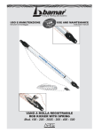
Installation and operating instructions
Barriers
ES 25 – ES 25HS – ES 30HS – ES 30 – ES 40 –
ES 50 – ES 50S – ES 60 – ES 80
1.
1.1.
1.2.
2.
2.1.
2.2.
3.
3.1
3.2.
3.3
4.
5.
6.
6.1.
6.2.
7.
8.
9.
10.
11.
12.
13.
Contents
Technical data ES 25 - ES 40
Dimensions ES 25 – ES 40
Installation ES 25 – ES 40
Technical data ES 50 - ES 80
Dimensions ES 50 – ES 80
Installation ES 50 – ES 80
Controller MO 63
Connections
Further connections
Visual indication
Operating mode MO 63
Photo-cell test
Programming
Running time and automatic closure
Setting personal code for radio remote
External connections
Layout in the barrier
Fault finding
Examples for use of loop detectors
Maintenance
Extra equipment (swinging support, folding boom)
General notes to safety
© 26.07.2006 ELKA-Torantriebe GmbH u. Co. Betriebs KG
ES 25 – ES 40 mit MO63
page
2
2
3
4
4
5
6
6
7
7
8
9
9
9
10
10
11
12
14
16
18
22
page 1
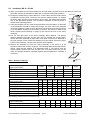
1.
Technical data ES 25- ES 40
Operative range
Application
- Parking area, parking garage
for ...
- Company entrance
- Safety area
- Toll-station
Drive pulse
- Push-button, card reader, key switch,
from ...
remote control, desk top panel etc.
- Handsfree data-capture
- Induction loop
Safety
- Reversing on obstacle
- Best protection against vandalism
- Ergonomic emergency release
Typical Data
Drawn power
Running time
Maximum boom length
Effective length
Reversing on obstacle
Boom weight
/{
Barrier weight
ES 25 *
0.37kW
ca. 1.4s
2500mm
2280mm
switchable
4 / 2kg
47.5kg
ES 25 HS *
0.37kW
ca. 0.9s
2500mm
2280mm
switchable
4 / 2kg
47.5kg
General Data
Mains supply
Max. current
Duty cycle
Temperature range
Controller
Measurements (w/l/h)
Foundation (frost-proof)
Boom connector
Housing
Mechanical parts
ES 30 HS *
0.37kW
ca. 1.4s
3000mm
2780mm
switchable
4.7 / 2.3kg
47.5kg
230V / 50Hz
2,5A
100%
-10°C to +70°C
MO 63
350x300x1100mm
550x500x800mm
left or right
aluminium
steel, zinc coated
ES 30
0.25kW
ca. 2.3s
3000mm
2780mm
switchable
4.7 / 2.3kg
47.5kg
ES 40
0.26kW
ca. 3.2s
4000mm
3780mm
switchable
6 / 3kg
50kg
* Vehicle traffic only
The accident prevention regulations and the approved safety rules have to be observed.
Moving parts inside the barrier can cause accidents.
Do not operate the barrier when housing is open.
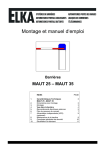
Measurements ES 25 – ES 40
820
1100
1.1.
300
350
Boom length m inus 360mm
Drilling tem plate
barrier housing
203
800
273
247
179
550
Fixed support
500
320
130
Panel/Roadway
110
140
160
Foundation
500x550x800
2500/3000/4000
© 25.02.2008 ELKA-Torantriebe GmbH u. Co. Betriebs KG
page 2
ES 25 – ES 80 (MO 63)
1.2.
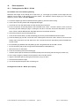
Installation ES 25 – ES 40
a) When you prepare the concrete foundation lay enough cable or a plastic duct for the cable you need.
The foundation must be at least 800mm deep with a horizontal surface 500 x 550mm.
b) Using the template you can, either incorporate bolts in the foundation, or drill holes in the hardened
concrete for heavy-duty fixings. The door side of the template must face towards the road on which the
barrier will be closing.
c) As an alternative 2 "U"-profile clamping-irons are delivered with the barrier. This gives more flexibility in
positioning the fastening points and allows the barrier to be aligned exactly as required.
Attention: The barrier is closed when shipped.
The door faces towards the road.
d) Secure the barrier on the foundation.
e) Connect the boom holder to the shaft. Tighten all screws, the top ones first with 35 Nm. The enclosed
nuts and bolts are a predetermined breaking point and should only be replaced with the same.
(Bolt M 8 x 45 ISO 4762 12.9, Nut hexagonal M 8 ISO 4032 5-2)
Release bolt
Boom holder
Release lever
Shaft
f) Emergency release during current failure etc. Pull the lever with the red end which is behind the access
panel. The boom can then be raised manually. To engage the boom again pull the lever and pull the
boom down, the release bolt will then lock at the appropriate position. The controller is switched off until
the boom is locked at the operating position.
g) Mount the boom before doing a test run. If necessary adjust the limit switches and the stoppers.
h) Start the programming mode (6.1 – Running time and automatic closure).
The logic board MO 63 is connected to the terminals (X1) in the barrier and to the microswitches in the head.
All electrical connections should be carried out at the front of the terminals (X1). The barrier is ready for use
when delivered. The running time and a ‘stay open’ time of 5 seconds are stored in an EEPROM.
You only need the programming mode if the time to stay open (when automatic closure is being used) is to
be altered, the photo-cell test is activated or when a controller is replaced.
Switch off the mains supply before altering the operating mode dip switches!
© 25.02.2008 ELKA-Torantriebe GmbH u. Co. Betriebs KG
page 3
ES 25 – ES 80 (MO 63)
2. Technical data ES 50- ES 80
Operative range
Application
- Parking area,
for ...
- Parking garage
- Company entrance
- Safety area
Drive pulse
- Push button, card reader, key switch,
from ...
remote control, desk top panel etc.
- Handsfree data-capture
- Induction loop
Safety
- Reversing on obstacle
- Best protecting against vandalism
- Ergonomic emergency release
Typical Data
Drawn power
Running time
Maximum boom length
Effective length
Fixed- / swinging support
Reversing on obstacle
Boom weight
/{
Barrier weight
ES 50
0.26kW
ca. 4.0s
5000mm
5140mm
required
switchable
10 / 9kg
110kg
General data
Mains supply
Max. current
Duty cycle
Temperature range
Controller
Measurements (w/l/h)
Foundation (frost-proofed)
Boom connector
Housing
Mechanical parts
ES 50S *
0.37kW
ca. 4.0s
5000mm
5140mm
required
switchable
10 / 9kg
110kg
ES 60
0.26kW
ca. 5.5s
6000mm
6140mm
required
switchable
16.5 / 11kg
115kg
230V / 50Hz
2.5A (max.)
100%
-10°C to +70°C
MO 63
400x450x1100mm
600x650x800mm
central
aluminium
steel, zinc coated
ES 80
0.26kW
ca. 8.5s
8000mm
8140mm
required
switchable
23 / 14kg
118kg
* Vehicle traffic only
The accident prevention regulations and the approved safety rules have to be observed.
Moving parts inside the barrier can cause accidents.
Do not operate the barrier when housing is open.
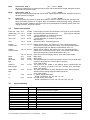
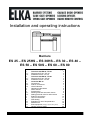
Measurements ES 50 – ES 80
13
2.1.
M
13
12
x6
5
M13
12
13
x6
5
M 12
13
x6
5
13
M13
12
1100
145
843
Length of boom
Drilling template
barrier housing
165
165
160
90
194
400
70
320
800
165
13
M 12
M 12
M 12
13
13
600
Panel/Roadway
165
13
Fixed support
13
130
286
13
110
450
13
140
160
5000/6000/8000
Foundation
600x650x800
650
© 25.02.2008 ELKA-Torantriebe GmbH u. Co. Betriebs KG
page 4
ES 25 – ES 80 (MO 63)
2.2. Installation ES 50 – ES 80
a) When you prepare the concrete foundation lay enough cable or a plastic duct for the cable you need. The
foundation must be at least 800mm deep with a horizontal surface 600 x 650mm.
c) Using the template you can, either incorporate bolts in the foundation, or drill holes
in the hardened concrete for heavy-duty fixings. The door side of the template
must face towards the road on which the barrier will be closing. Secure the barrier
on its foundation. Ensure that the housing is vertical. The screws or bolts at the
thickly marked points (drawing on page 4) also secure the foot of the spring
assembly.
Release lever
Boom
assembly
d) The left and right parts of the boom assembly aren’t identical. The greater
distance between the edge and the hub must be towards the access panel.
Secure the boom assembly on both ends of the shaft. The barrier is delivered in
the open position, which means the assembly must be vertical. Secure the boom
holder on the assembly. The two parts are then joined together.
Panel
e) Remove the adjusting nut from the spring assembly. If the boom is to be
shortened reduce the number of springs. The following table shows approximate
values, check that the balance is as described under f). The springs must be
divided equally between the back and the front. One spring alone may not be
used. The springs should be inspected regularly and be tightened or replaced, if
necessary.
Counter nut
Adjusting
nut
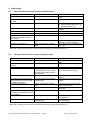
Table – Number of springs
Number of springs ES 50 / ES 50S
Length of boom [mm]
without accessories
with swinging support
with folding skirt 75
with folding skirt 75 and swinging support
Number of springs ES 60 / ES 80
Lenght of boom [mm]
without accessories
with swinging support
with folding skirt 75
Spring assembly
Release bolt
b) Emergency release during current failure etc. Pull the lever with the red end which
is behind the access panel. The boom can then be raised manually. To engage
the boom again pull the lever and pull the boom down, the release bolt will then
lock at the appropriate position. The controller is switched off until the boom is
locked at the operating position.
3.000
3.500
4.000
4.500
5.000
2
2
2
3
2
2
3
3
2
3
4
4
3
3
4
5
3
4
5
5
4.000 4.500 5.000 5.500 6.000 6.500 7.000 7.500 8.000
3
4
5
4
5
6
5
6
7
6
6
8
6
6
9
8
10
12
10
11
13
11
12
15
12
13
17
with folding skirt 75 and swinging support
5
6
7
8
9
12
14
16
18
with top and bottom skirt 150
with folding skirt 150
7
7
8
9
10
11
11
13
13
15
x
x
x
x
x
x
x
x
The following values are for round booms only.
Number of springs ES 50 - ES 80
Lenght of boom [mm]
without swinging support
with swinging support
3.000 4.000 4.500 5.000 5.500 6.000 7.000 8.000
© 25.02.2008 ELKA-Torantriebe GmbH u. Co. Betriebs KG
2
2
page 5
3
3
3
4
4
4
4
5
5
6
10
11
ES 25 – ES 80 (MO 63)
11
12
f) When all electrical connections are completed, ensure that the spring assembly is not yet connected to
the drive shaft. Close the barrier with the motor and then mount the boom. Pull the emergency release
lever and push the boom into the vertical position. Screw the adjusting nut onto the connecting rod and
tighten the springs. Pull the release lever again and push the boom down, if the spring tension is correct,
it should move easily to about 45°. After that the boom has to be pushed down.
ATTENTION!
In position CLOSED the barrier boom shall not be pushed upwards by the fixed or
swinging support! Press the barrier boom slightly downwards when pulling the
emergency release lever.
g) The connecting rod of the ES 50 to ES 80 consists of two parts which
are screwed together and form a predetermined breaking point in case
of vertical force on the boom. The boom is then disconnected from the
shaft and is pulled to about 45° by the springs. If a break occurs here
the nut and the bolts must be replaced with the original vandalism set.
The
nuts
must
be
secured
with
thread
lock.
The nuts may only be replaceed with those supplied by your
supplier.
Shaft
Pre-determined
breaking point
h) Start the programming mode (6.1 – Running time and automatic
closure).
The logic board MO 63 is connected to the terminals (X1) in the barrier and to the microswitches in the
head. All electrical connections should be carried out at the front of the terminals (X1). The barrier is
ready for use when delivered. The running time and a ‘stay open’ time of 5 seconds are stored in an
EEPROM.
You only require the programming mode if the time to stay open (when automatic closure is being used)
is to be altered, the photo-cell test is activated or when a controller is replaced.
Switch off the mains supply before altering the operating mode dip switches!
© 25.02.2008 ELKA-Torantriebe GmbH u. Co. Betriebs KG
page 6
ES 25 – ES 80 (MO 63)
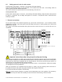
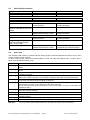
3. Controller MO 63
LERN
BT
BT
1
BTA
BTA1
2
BTZ1
BTA2
Diag. Vp
3
V9
BTZ2
4
BTZ1A
6
BTS1
BTS2
7
1 2 3 4 5 6 7 8 9 10
VWA1
VWA2
VWZ
ZLA
REV.
ZAHL
SZ
LSA
LSTST
RES.
1
SEA
Operating mode
Barrier open
Barrier closed
common
SEZ
Receiver radio
remote control
ON
SEA
10 11 12 13 14
No boom
2
V6
SEZ
BTS2
9
BTZ1B
8
LS
B1
V14
5
LS
BTS1
V15
BTZ2
3
1
No boom
3
V4
2
Stop
4
Photo-cell test 24V
Transformer
MO63
1
3
V12
2
24Vdc max. 500mA
12Vdc max. 500mA
4
10A
3
4
5
6
Fuse
2
1
7
V2
M
Motor
3.1.
Red light
Green light
Barrier closed
Barrier open
Amber or
L1
flashing light
230V
max. 120W
N
50Hz
Connections
BT
Single push button
(n.o. – V15.1 – X1/5t)
With the serial switching BT the barrier can be opened and closed. Additional functions of BT
depend on setting of the dip switches for automatic closure (S4) and the counter settings (S6).
When the automatic closure is activated, or the counter is deactivated, then the barrier can be
closed by BT – otherwise the barrier will be opened. When the automatic closure is blocked (e.g.
by a stop signal), and the counter is activated, then BT can only open the barrier. Which means
that closing by BT is not possible.
BTA1
BTA2
Push button ‘open’ 1 and 2
(n.o. – V15.2 – X1/6t and V15.3 – X1/6b)
When one of the contacts BTA1 or BTA2 is open and the other is closing, the barrier opens.
When the barrier is open and BTA1 or BTA2 is being closed, then the barrier cannot be closed
(constant open).
BTZ1A
Push button ‘close’ 1A and 1B
(n.o. – V15.4 – X1/7t and V15.9 – X1/10b)
When BTZ1A closes while BTZ1B is open, or BTZ1B closes while BTZ1A is open, the barrier
closes. When the barrier is closed and at least one contact is closed, the barrier cannot be
opened (constant closed).
BTZ2
Push button ‘close’ 2
(n.o. – V15.5 – X1/7b)
When the contact BTZ2 is opening, the order ‘close’ is given.
© 25.02.2008 ELKA-Torantriebe GmbH u. Co. Betriebs KG
page 7
ES 25 – ES 80 (MO 63)
BTS1
Push button ‘stop’ 1
(n.o. – V15.6 – X1/4t)
When the contact BTS1 is closed the barrier stops. Stored signals are erased. Automatic closure
is blocked until the next signal.
BTS2
Push button ‘stop’ 2
(n.c. – V15.7 – X1/8b)
When the contact BTS2 is open the barrier stops. Stored signals are erased. Automatic closure is
blocked until the next signal.
LS
Photo-cell
(n.c. – V15.8 – X1/9b)
When the photo-cell reports an obstacle the barrier cannot be closed. During the opening of the
barrier an existing obstacle is not report. When an obstacle is reported during closing, the barrier
stops and reverses. Additional functions of the photo-cell depend on operating mode, photo-cell
closing automatic, and photo-cell test.
3.2.
Further connections
Photo-cell +24V V4.4
(transmitter) 0V V12.1
Uext +24V
V12.2
X1/26b
X1/26t
X1/1b
Uext +12V
V12.3
X1/3b
Gnd
V12.4
X1/2b
Display
‘barrier open’
V15.12
X1/11t
Display
‘barrier closed’
V15.13
X1/12t
V15.14
X1/11b
Motor
Motor
Red traffic
light
V2.1
V2.2
V2.3
X1/20
X1/22
X1/13t
Amber or
flashing light
V2.4
X1/14t
Green traffic
light
V2.5
X1/15t
L1
V2.6
X1/17b
N
V2.7
X1/19b
3.3.
LED
Power supply for photo-cell transmitter +24V (only for photo-cell test).
Ground for photo-cell transmitter 0V
(only for photo-cell test).
+ 24Vdc stabilised, for external equipment.
Max. 500 mA (for V12.1 + V12.2)
+ 12Vdc stabilised, for external equipment.
Max. 500 mA
Ground for Uext – external equipment
Display ‘barrier open’. The contact V15.12 is connected with the
contact V15.14 when the barrier is open. The contact will be closed
when the green light is lit. Maximum permissable: 24V / 1A.
Display ‘barrier closed’. The contact V15.13 is connected with the
contact V15.14 when the barrier is open. The contact will be closed
when the red light is lit. Maximal admissible: 24V / 1A.
Common terminal for display ‘barrier open’ and ‘barrier closed’.
Motor open
Motor close
The red traffic light is on when the barrier is closed. The red traffic light
is also on during the time ‘warning prior to opening’.
(max. 230V/120W)
The contact for the Amber or the flashing light is closed when the
barrier is moving and during the time ‘warning prior movement’.
(max. 230V/120W)
The green traffic light is on when the barrier is open. During the time
‘warning before closing’ the green traffic light is out.
(max. 230V/120W)
L1, power supply 230V 50Hz
further connections : X1/ 16t, 16b, 17t, 17b
N, power supply 230V 50Hz
further connections: X1/ 13b, 14b, 15b, 18t, 18b, 19t, 19b
Visual indication
Colour
BT
green
BTA
BTZ1
BTZ2
BTS1
BTS2
LS
SEA
SEZ
Vp
Diag
green
green
green
green
green
green
green
green
yellow
red
Function
LED is lit when contact BT is closed or the receiver of the radio
remote control receives a signal.
LED is lit when contact BTA1 or BTA2 is closed.
LED is lit when contact BTZ1A or BTZ1B is closed.
LED is lit when contact BTZ2 is closed.
LED is lit when contact BTS1 is closed.
LED is lit when contact BTS2 is closed.
LED is lit when the photo-cell is activated.
LED is lit when contact SEA is closed.
LED is lit when contact SEZ is closed.
LED is lit when the main power is on.
Error code and display for radio remote control.
© 25.02.2008 ELKA-Torantriebe GmbH u. Co. Betriebs KG
page 8
ES 25 – ES 80 (MO 63)
4. Operating mode MO63
Switch off the mains supply before altering the operating mode dip switches 1 - 9!
4.1.
Pre-warning before opening (S1 und S2=VWA)
The warning light (flashing or amber light) illuminates right after a signal to open, if pre-warning time before
opening is activated.The barrier opens after the pre-warning time has elapsed.
S1 off and S2 off:
S1 off and S2 on:
S1 on and S2 off:
No pre-warning time.
1.5 s pre-warning time before opening.
4.0 s pre-warning time before opening.
4.2.
Pre-warning before closing (S3=VWZ)
The warning light (flashing or amber light) goes on right after a signal to close, if pre-warning time before
closing is activated.The barrier closes after the pre-warning time has elapsed.
S3 off:
S3 on:
No pre-warning time before closing.
4.0 s pre-warning time before closing.
4.3.
Automatic closure (S4=ZLA)
The open barrier closes automatically after the programmed ‘stay open time’ has elapsed. An earlier closing
of the barrier is possible by BT or BTZ. Is a stop signal given during the stay open time, then the automatc
closure is blocked and is only released again by a new signal. BTA1, BZA2, or LS keep the barrier in the
end-position ‘open’ even after the stay open time has elapsed. The barrier closes immediately when a signal
BTA1, BTA2, or LS is removed.
S4 off:
S4 on:
No automatic closure.
The barrier closes after the time which was saved during the setup (0 s up to 300 s).
4.4.
Reversal on hitting obstacles (S5=REV)
When learning the running time during the setup the torque power for the reversing on obstruction is
determined. When the barrier boom hits an obstacle during closing and blocks, the controller stops the
movement or gives an ‘open’ signal.
S5 off:
S5 on:
The closing boom stops when it hits an obstacle and re-opens immediately.
The closing boom stops when it hits an obstacle and only moves when a new signal
is received.
4.5.
Counting (S6=ZÄHL)
The signals ‘open’ and ‘close’ are counted by the controller.
S6 off:
S6 on:
No counting. The barrier closes after one signal to close, even after two signals to
open.
Counting is activated. The barrier closes after two signals to close if there were two
consecutive opening signals.
4.6.
Reversal during opening (S7=SZ)
When a ‘close’ signal is received during opening, the barrier will either open completely and then close or the
barrier closes immediately.
S7 off:
S7 on:
The barrier always opens completely before reacting to a signal to close.
The opening barrier reverses immediately when it receives a signal to close.
4.7.
Automatic closure by photo-cell (S8=LSA)
The photo-cell always gives a signal to close, when the obstacle is not longer present.
S8 off:
S8 on:
Automatic closure by photo-cell is not activated. The closing function by loop B3/2 is
not applicable.
When an obstacle is not longer present the barrier closes.
4.8.
Photo-cell test (S9=LSTST)
Before each closing of the barrier, the photo-cells may be tested.
S9 off:
S9 on:
Photo-cell test is not activated.
A photo-cell test occurs before each closing.
Attention: The photo-cell test has to be learnt when programmimg the controller.
© 25.02.2008 ELKA-Torantriebe GmbH u. Co. Betriebs KG
page 9
ES 25 – ES 80 (MO 63)
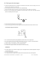
5. Photo-cell test
Before the closing of the barrier, the photo-cells may be tested. The photo-cell test consists of two parts.
Part one: The transmitter is taken off the power supply and then the receiver has to report an obstacle (within
max. 2.5 seconds).
Part two: The transmitter is connected to the power supply again and then the receiver has to report that no
obstacle is present.
If during part one the receiver does not report an obstacle, the photo-cell is faulty and an error code is shown
on the Diag.-LED (flashes 6 times). If during part two the obstacle is still being reported (the controller
assumes a real obstacle being present), the barrier will not close. No error code is shown.
Max. 6 photo-cells can be connected to the controller MO63 and be tested. For the testing of more than one
photo-cell the relay connections of the receivers have to be connected in series. Parallel to the relay
connections a resistor of 1kΩ each has to be connected.
1
3
R1
T1
2
1
2 4
1
3
T2
R2
2
1
2
1
4
3
R3
T3
2
1
2
1
For the photo-cell test the controller MO63 has to
learn the quantity of photo-cells which are
connected, by activating the dip switch S9=on and
learning the running time again.
4
3
R6
T6
2
1
X1/26o X1/26u
2
4
X1/1u X1/2u
X1/9o X1/9u
Terminal X1
6. Programming
The controller has to learn the following parameters:
- Running time for opening and closing
- Torque power for reversal on hitting an obstruction.
- Quantity of photo-cells when the photo-cell test is activated
- Time to stay open for automatic closure
- Personal code for radio remote control
On delivery 5 seconds open before automatic closure and the running time for the barrier are already
saved.
6.1.
Running time and automatic closure
a) Push the learn button approx. 3 seconds – the red Diag.-LED starts flashing.
b) Push the learn button again. When the photo-cell test is activated (S9=on) the controller learns how many
photo-cells are connected. During learning the Diag.-LED flashes at 1 second intervals, then the learning
of the running time starts automatically.
When the photo-cell test is not activated (S9=off) the learning of the running time starts immediately.
c) The Diag.-LED is lit during the learning of the running time. The barrier closes if it is not closed already. If
it is closed then it opens and learns the running time for opening. Then the Diag.-LED flashes at 1 second
intervals and the controller learns the stay open time.
d) After the required stay open time push the learn button again. The barrier closes automatically and learns
the running time for closing and the torque power for the reversing on obstruction. The learnt values are
stored even if power failure occurs and the Diag.-LED turns off.
© 25.02.2008 ELKA-Torantriebe GmbH u. Co. Betriebs KG
page 10
ES 25 – ES 80 (MO 63)
6.2.
Setting personal code for radio remote
Push the learn button approx. 3 seconds – the red Diag.-LED starts flashing.
Push the corresponding button on your transmitter. The contoller learns the code - the red Diag.-LED is lit
while a signal is received. Release the button.
The code is stored even if power failure occurs and the Diag.-LED turns off.
Cancel personal code
Push the learn button approx. 3 seconds – the red Diag.-LED starts flashing. Keep the learn button pushed
for approx. 10 seconds. The red Diag.-LED lights for 2 seconds – the personal code is erased and the
learning is finished.
7. External connections
For the power supply of the external equipment (e.g. photo-cells, induction-loops....) the controller provides
stabilised 24 Vdc and 12 Vdc. Max. 500 mA can be drawn from the 12 V source and the 24 V source, but
together max. 700 mA.
The supply of the photo-cell transmitter during photo-cell test comes from the 24 V source and has to be
considered.
loop 2
(B3/2)
loop 1
(B3/1)
loop 3
(B2)
red jumper
Barrier open (green light)
Barrier moving, or about to move (amber, or flashing light)
Barrier closed (red light)
Photo-cell
X1/9t
X1/9b
Stop
X1/8t
X1/8b
ON / OFF
Serial switching
No boom (option)
Barrier open
Boom open
Barrier close
Boom closed
Important instructions when using loops for safety and closing
When using a loop-detector for safety remove the red jumper between contects 6 and 10 on the socket B3.
The socket B3 is always for the loop under the barrier boom, and is prewired for safety and for closing when
leaving the loop. When B3 is equipped with a 2-channel-detector, the second channel may be used for an
opening loop or a loop detecting that a vehicle is present.
The socket B2 is prewired for an opening loop in connection with a 1-channel-detector. Please see chapter
10 “Examples for use of loop detectors”.
When all connections are completed and the barrier is closed, only the following LEDs should be lit:
the yellow LED Vp for main power, the green LED SEA and the green LED BTS2.
If is not the case then see chapter 9 “Fault finding”.
Warning: Please check the direction of rotation of the transmission lever of the gearbox. The reversal by
obstruction can only work when the rod always moves to the rear of the housing, never to the door.
© 25.02.2008 ELKA-Torantriebe GmbH u. Co. Betriebs KG
page 11
ES 25 – ES 80 (MO 63)
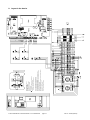
© 25.02.2008 ELKA-Torantriebe GmbH u. Co. Betriebs KG
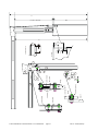
B2: socket for 1-channel detctor
loop 3: 1-channel detector for opening
loop 1: 1-channel detector for safety and closing
loop 1: 2-channel detector for safety and closing
loop 2: 2-channel detector for opening
If a 1-channel detector is used, remove the jumper between 27b-6b.
If a 2-channel detector is used, remove the jumper between 25b-25t and
set operating mode switch 8 ON.
If loop 2 is used for presence, do not remove the jumper between 25b-25t.
Set push button between 27b and 6b.
B3: socket for 1- or 2-channel detector
If a detector is used, remove the red jumper.
B1: receiver radio remote control
S1: limit switch OPEN
S2: limit switch CLOSED
S5: push button OPEN / CLOSE
S6: switch "no boom" (optional)
S0: switch "STOP"
: upper and lower terminals connected internally
8. Layout in the barrier
page 12
ES 25 – ES 80 (MO 63)
9. Fault finding
9.1.
The closed barrier doesn’t react to a signal to open
Symptom
Possible cause
Possible solution
The yellow power LED is out.
No mains supply.
The red diagnostic LED flashes
non-stop.
The green LED BTS1 is lit.
Programming is started.
Check the mains lead and the
fuses.
Carry it out to the end.
The controller is switched off.
The green LED BTS2 is out.
a) The stop button is pressed.
b) Emergency release in use.
c) Wiring fault.
The green LED SEA is out and the a) Faulty limit switch ’open‘.
red Diag.-LED flashes 4 times –
then a break.
b) Wiring faulty
The green LED BTZ1 is lit.
There is a permanent signal to
close.
a) Operating mode switch 1 off.
b) Switch On/Off switch (X1/4 top
and X1/4 bottom off).
Release the button (X1/8 top and
bottom).
Lock the shaft.
Check the wiring.
Replace the limit switch.
Check the wiring to the limit switch
and plug V6 on the controller.
Check the button (X1/2 bottom/top
and 7 top).
When the controller gives an error code through the red Diag.-LED see the chapter 9.4.
9.2.
The open barrier doesn’t react to signals to close
Symptom
Possible cause
Possible solution
The yellow power LED is out.
No mains supply.
The red diagnostic LED flashes
non-stop
The green LED LS is lit.
Programming is started.
Check the mains lead and the
fuses.
Carry it out to the end.
The green LED LS is lit when the
photo-cell is free, and not lit when
an obstacle is present
The green LED BTA is lit.
a) Loop detector is activated.
b) The red jumper is removed from
the terminals 6 and 10 in socket
B3, but the loop detector hasn’t
been inserted.
c) The photo-cell is activated.
The photo-cell is connected as
normally open.
There is a permanent signal to
open.
The green LED SEZ is out and the a) Faulty limit switch ’closed‘.
red diagnostic LED flashes 4 times
– then a break.
b) Wiring fault.
The green LED BTZ2 is lit.
Check the detector in socket B3.
Plug the detector into the socket
B3 or replace the red jumper.
Check it (X1/9 top and X1/9
bottom).
Connect the photo-cell as normally
closed.
a) Check the ’open‘ button (X1/2
bottom and X1/6 top)
b) Check the loop detector in
socket B2
Replace the limit switch.
Check the wiring and plug V6 in
the control box.
There is a permanent signal to the Check the button (X1/7 bottom and
terminals BTZ2.
X1/2 bottom/top)
When the controller gives an error code through the red Diag.-LED see the chapter 9.4.
© 25.02.2008 ELKA-Torantriebe GmbH u. Co. Betriebs KG
page 13
ES 25 – ES 80 (MO 63)
9.3.
Fault finding continued
Symptom
Possible cause
Delay before opening.
Warning is active.
Delay before closing.
Warning is active.
The barrier does the following when it hits an obstacle ...
...switches off.
Reversing is not activated.
...tries to carry on closing.
Torque setting is wrong.
The boom isn’t vertical when the barrier is open ...
The green LED SEA is out.
Limit switch ‘open’ maladjusted,
but still switches.
The green LED SEA is lit. The red a) Faulty limit switch ‘open’.
diagnostic LED flashes twice then
a break.
b) The limit switch ‘open‘ is
maladjusted and doesn’t switch.
The boom isn’t horizontal when the barrier is closed...
The green LED SEZ is out.
Limit switch ’closed‘ maladjusted,
but still switches.
The green LED SEZ is lit. The red a) Faulty limit switch ’closed‘.
diagnostic LED flashes three
times – then a break.
b) The limit switch ’closed‘ is
maladjusted and doesn’t switch.
9.4.
Possible solution
Operating mode switch 1+2 off.
Operating mode switch 3 off.
Operating mode switch 5 off.
Adjust it.
Re-adjust it and the corrsponding
mechanical stopper.
Replace it.
Re-adjust it and the corrsponding
mechanical stopper.
Re-adjust it and the corrsponding
mechanical stopper.
Replace the limit switch.
Re-adjust the limit switch and the
corresponding mechanical stopper.
Error code
The red Diag.-LED serves as a status indicator. During regular, fault free operation the LED is only lit, when
a radio remote signal is received.
An error code is given, when the controller detects a fault. the Diag.-LED flashes max. 12 times, then a
break, then repeats the flashing code.
Error code
2 x flashing
3 x flashing
4 x flashing
5 x flashing
6 x flashing
7 x flashing
8 x flashing
9 x flashing
10 x flashing
11 x flashing
12 x flashing
Attention:
Cause/solution
Limit switch “OPEN” did not open after the learnt running time. The limit switch has a short
circuit.
Limit switch “CLOSE” did not open after the learnt running time. The limit switch has a short
circuit.
Both limit switches signal at the same time. While SEA and SEZ signal at the same time, the
controller is blocked.
The power supply limit for the external equipment 12 V and/or 24 v has been reached. The
power source load is too high. The controller is blocked. Check the connected equipment.
Photo-cell error. The following error occurred during the photo-cell test. The transmitter is
inactive but the receiver does not signal an obstacle.
An error occurred during learning of the torque power for the reversing on obstacle. Either
the controller, the motor, or the capacitor of the motor are faulty.
Check the above and repeat the learning of the running time. If the error still exists the
controller is faulty.
The EEPROM has lost the data. Repeat the learning of the running time. If the error still
exists the controller is faulty.
The EEPROM is faulty.
The controller has detected a fault in the redundant detection of the “stop” contact. The
controller is faulty.
One of the motor relays has not switched off. The controller is faulty.
The controller detects that the “Triac” has not switched off. The controller is faulty.
You may use the service device ZS701 to read the error memory of the controller.
© 25.02.2008 ELKA-Torantriebe GmbH u. Co. Betriebs KG
page 14
ES 25 – ES 80 (MO 63)
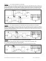
10.
Examples for use of loop detectors
B3/2 This loop may be used for opnening or for detecting that a vehicle is present (connected to socket B3
by contacts X1/24 top und X1/24 bottom).
B3/1 This loop is for the safety only and is placed under the barrier boom (connected to socket B3 by
contacts X1/23 top und X1/23 bottom).
B2
This loop is for opening only (connected directly to socket B2 – contacts 7 and 8).
Push button, key switch, card reader, coin selector, etc.
Photo-cell
Example 1
(for 1-channel loop detector on socket B3)
Entrance and Exit – opening with push button. Safety and closing with loop detector on socket B3/1 (all
jumpers at default settings).
Remove red jumper of socket B3 and jumper between the terminals 27 bottom and 6 bottom.
2526 27 1 2 3
4 5 6 7 8 9 10
OUT
IN
B3/1
Example 2
(for 2-channel loop detector on socket B3)
Entrance – opening with a key switch. Safety and closing with both loops B3/1 and B3/2.
Exit - opening with loop B3/2. Safety and closing with both loops (all jumpers at default settings).
Remove red jumper of socket B3 and jumper between the terminals 25 top and 25 bottom. DIP S8 = ’on’.
2526 27 1 2 3
min. 1000 mm
max. 1500 mm
IN
B3/1
Example 3
4 5 6 7 8 9 10
OUT
B3/2
(for 1-channel loop detector on socket B3)
Entrance and Exit – opening with a coin selector. Safety with photo-cells and loop B3/1. Automatic closure
when the time to stay open has elapsed. Remove the jumper between 9 top and 9 bottom and connect the
safety contact of the photo-cells to them (all jumpers at default settings). Remove red jumper of socket B3
and jumper between the terminals 27 bottom and 6 bottom.
.
2526 27 1 2 3
4 5 6 7 8 9 10
OUT
IN
B3/1
© 25.02.2008 ELKA-Torantriebe GmbH u. Co. Betriebs KG
page 15
ES 25 – ES 80 (MO 63)
Example 4
(for 2-channel loop detector on socket B3)
Entrance and Exit - with card reader. The loop B3/2 allows use of the card reader only when a vehicle is on
the loop. The loop B3/1 is for safety, and closing when a vehicle leaves the loop. The jumpers are at the
default settings. Remove the jumper between terminals 6 bottom and 27 bottom and connect the contact
from the card reader here. The red jumper on socket B3 between terminals 6 and 10 must remain in place.
min. 1000 mm
max. 1500 mm
OUT
B3/1
B3/2
2526 27 1 2 3
min. 1000 mm
max. 1500 mm
IN
B3/2
Example 5
4 5 6 7 8 9 10
B3/1
(for 1-channel loop detector on socket B2 and 2-channel loop detector on socket B3)
Entrance – with card reader. The loop B3/2 allows use of the card reader only when a vehicle is on the loop.
Remove the jumper between terminals 6 bottom and 27 bottom and connect the contact from the card
reader here. Safety with loop B3/1, opening with loop B2, closing with B3/1 or B2. Remove the red jumper of
socket B3 and set DIP-switch S8 ’on’.
2526 27 1 2 3
min. 1000 mm
max. 1500 mm
IN
B3/2
Example 6
min. 1000 mm
max. 1500 mm
4 5 6 7 8 9 10
OUT
B3/1
B2
(for 2 x 1-channel loop detector on socket B2 and socket B3)
Entrance – opening with key switch. Safety with loop B3/1, closing with both loops B3/1 or B2.
Exit – opening with loop B2, safety and closing with B3/1.
Remove red jumper of socket B3 and jumper between the terminals 27 bottom and 6 bottom.
2526 27 1 2 3
min. 1000 mm
max. 1500 mm
IN
B3/1
© 25.02.2008 ELKA-Torantriebe GmbH u. Co. Betriebs KG
4 5 6 7 8 9 10
OUT
B2
page 16
ES 25 – ES 80 (MO 63)
11.
Maintenance
11.1.
Maintenance ES 25 – ES 40
The maintenance intervals must be decided individually as they are dependent on the frequency of use. We
recommend maintenance at least once every six months.
a. Check everything for mechanical damage and replace where necesary.
b. Check that the boom reaches the horizontal and vertical positions. If necessary re-adjust the limit
switches and the mechanical stoppers.
c.
Ensure that the potential earthing cable is still connected to the housing and to the door.
d. Check that the operating instructions are complete.
e. Check that all safety equipment works properly (Loops, photo-cells, and the reversal on obstruction).
f.
Check that the barrier is still secure on the foundation.
g. Using a grease gun, grease the bearings of the main shaft (grease must be suitable for –25°C to
+125°C).
h. Check the plastic screws at the boom holder.
i.
Oil the emergency release bolt and check the function.
j.
Check that the pre-determined breaking point has the correct nuts and bolts (bolts M8x45 ISO 4762 12.9
and nuts M8 ISO 4032 5-2).
k.
Tighten screws where necessary.
11.2.
Maintenance ES 50 – ES 80
The maintenance intervals must be decided individually as they are dependent on the frequency of use. We
recommend maintenance at least once every six months. The springs are designed for 250,000 openings.
a. Check the spring assembly. In case of faulty springs all springs must be replaced at once.
b. Check the spring tension as explained in 2.2.
c.
Check everything for mechanical damage and replace where necesary.
d. Check that the boom reaches the horizontal and vertical positions. If necessary re-adjust the limit
switches and the mechanical stoppers.
e. Ensure that the potential earthing cable is still connected to the housing and to the door.
f.
Check that the operating instructions are complete.
g. Check that all safety equipment works correctly. (Loops, photo-cells, and the reversal on obstruction.)
h. Check that the barrier is still secure on the foundation.
i.
Using a grease gun, grease the bearings of the main shaft. (grease must be suitable for –25°C to
+125°C.)
j.
Oil the emergency release bolt and check the function.
k.
Check that the pre-determined breaking point has the correct nuts and bolts (use vandalism set only).
l.
Tighten screws where necessary.
© 25.02.2008 ELKA-Torantriebe GmbH u. Co. Betriebs KG
page 17
ES 25 – ES 80 (MO 63)
12.
Extra equipment
12.1.
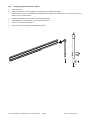
Folding boom for ES 25 – ES 40
All numbers refer to the following drawing.
Determine the length of the vertical part of the boom (1). The length (L3) should not be longer than the
distance from the deck to the ceiling (L1) minus 945mm. The maximum vehicle height (L2) is the ceiling
height (L1) minus 160mm. L3 max. 1500mm.
a. Screw the support (6) with the internal reinforcing plate (7) onto the barrier casing.
b. Cut the boom into two pieces with the appropriate length.
c. Cut off 60 mm from the rubber tube from the vertical part of the boom.
d. For the connection of the side plates to the horizontal boom, drill 2 x 2 holes ø 6,5mm in the cut end of
the boom (find the drawing on page 11).Using the four M 6 x 45 bolts, secure the side plates (3) on the
boom. Place a washer M6 between side plate and boom to maintain clearance.
e. Screw the pivot bolt (13) onto the support (6).
f. Push the short brass bush (14) and the bearing (8) onto the pivot bolt M8x50 and secure them.
g. Push the bearing (9) into the cut off end of the vertical part of the boom. Drill 2 holes ø 5,0mm from the
bottom side in the boom (15 and 40mm from the cut end) and secure the bearing with two M5x60 hex.
socket screws.
h. Fit the bearing (9) between the side plates (3) with a long brass bush and an M8 x 50 bolt.
i. Fit the connecting rod (5) with a long brass bush between the side plates (3).
j. Mount the boom on the barrier.
k. Push the connecting rod into the bearing (8).
l. Hold the second part of the boom horizontal and clamp the connecting rod with the grub screws (15).
m. Pull out the emergency release bolt and push the boom into the vertical.
n. Align the horizontal part by moving the pivot screw (13) up or down.
o. Check that all screws are tight.
p. Cut off the superfluous part of the connecting rod.
Folding boom for ES 50 – ES 80 upon inquiry.
© 25.02.2008 ELKA-Torantriebe GmbH u. Co. Betriebs KG
page 18
ES 25 – ES 80 (MO 63)
© 25.02.2008 ELKA-Torantriebe GmbH u. Co. Betriebs KG
page 19
brass bush (short)
13
6
8
7
14
15
4
11
1
9
12
12
5
45
ø8.5
ø8.5
Housing
110
10
62.5
bearing
connecting rod
bearing
side plates
connecting rod
3
10
horizontal boom
L3 (max. 1500 mm)
support
side plates
brass bush (long)
horizontal boom
2
3
L1
830
L2
105
55
ES 25 – ES 80 (MO 63)
12.2.
a.
Swinging support for ES 40 – ES 80
Close the barrier.
b.
Using the screws ‘B’, connect the upper and lower parts in the approximate length.
c.
Remove about 500 mm of the rubber tubing under the boom and push the securing piece ‘A’ into the slot. Secure it
with the two hex. socket screws.
d.
Push the rubber tube into the slot and cut off the protruding part.
e.
A fine adjustment of the length can now be made on the foot ’D’.
f.
Screw a 4 mm screw into the hole ‘E’.
g.
The foot can now be screwed to the appropriate position.
© 25.02.2008 ELKA-Torantriebe GmbH u. Co. Betriebs KG
page 20
ES 25 – ES 80 (MO 63)
12.3. Fixed support with electromagnet
a. Connect the flexible lead from the magnet to the cable from the barrier. There is enough room in the
lower part of the support for a junction box.
b. Fit the forked part onto the foot and secure it in the required height.
c. Remove the rubber tube from the boom at the point at which the anchor plate is to be secured.
d. Push one of the securing pieces, followed by the anchor plate, into the slot of the boom until the
plate is immediately above the magnet.
e. Push the second securing piece up to the magnet.
f. Push the securing pieces from both sides against the anchor plate and secure them with the screws.
Connecting the magnet in the barrier
12
22
11
21
A1
A2
14
top
1
14
bottom bottom
2
top
Magnet
a. The 4 seconds warning before opening must be activated. Switch 2 on the logic board.
b. The coil of the relay must be connected to the terminals ‘14 top’ and ‘14 bottom’ in the terminal block.
c. Connect contact 11 of the relay to ‘1 bottom’ in the terminal block.
d. Connect contact 21 of the relay to ‘2 top’ in the terminal block.
e. The leads to the magnet come from the contacts 12 and 22 of the relay.
OPERATION:
a. The relay switches off on receipt of a signal to open. The magnet loses it’s residual magnetism during the
4 seconds warning time.
b. The barrier opens after the 4 seconds.
c. The magnet switches on again when the barrier reaches the limit switch at the closed position.
© 25.02.2008 ELKA-Torantriebe GmbH u. Co. Betriebs KG
page 21
ES 25 – ES 80 (MO 63)
13.
General notes of safety
These operating instructions must be available on site at all times. It should be read thoroughly by all
persons who use, or service the appliances. Improper usage or servicing or ignoring the operating
instructions can be a source of danger for persons, or result in material damage. If the meaning of any part
of these instructions isn’t clear, then please contact ELKA Torantriebe GmbH u. Co. Betriebs KG before you
use the appliance.
This applies to all setup procedures, fault finding, disposal of material, care and servicing of the appliance.
The accident prevention regulations and applicable technical regulations (e.g. safety or electrical) and
environment protection regulations of the country in which the appliance is used also apply.
All repairs on the appliances must be carried out by qualified persons. ELKA Torantriebe GmbH u. Co.
Betriebs KG accepts no liability for damage which is caused by using the appliance for purposes other than
those for which it is built.
ELKA Torantriebe GmbH u. Co. Betriebs KG cannot recognise every possible source of danger in advance.
If the appliance is used other than in the recommended manner, the user must ascertain that no danger for
himself or others will result from this use. He should also ascertain that the planned use will have no
detrimental effect on the appliance itself. The appliance should only be used when all safety equipment is
available and in working order. All faults which could be a source of danger to the user or to third persons
must be eliminated immediately. All warning and safety notices on the appliances must be kept legible.
All electrical periphery equipment which is connected to the appliance must have a CE Mark, which ensures
that it conforms to the relevant EEC regulations. Neither mechanical nor electrical alterations to the
appliance, without explicit agreement of the manufacturer, are allowed. All alterations or extensions to the
appliance must be carried out with parts which ELKA Torantriebe GmbH u. Co. Betriebs KG have defined as
suitable for such alterations, and be carried out by qualified personnel.
Any contravention of these conditions revokes the manufacturer’s guarantee and also the CE Mark and the
user is alone responsible for the consequences.
Our service department is available to answer all queries about these conditions and, of course, about our
appliances.
The operation of the system within CEN countries must also be conformant with the European safety-relevant
directives and standards.
We reserve the right to make technical improvements without prior notice.
© 25.02.2008 ELKA-Torantriebe GmbH u. Co. Betriebs KG
page 22
ES 25 – ES 80 (MO 63)