1
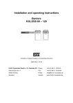
Installation and operating instructions Barriers ES 25 – ES 80 with MO 63 Translation of original operating manual D-ID: V5_0 – 12.12 ELKA-Torantriebe GmbH u. Co. Betriebs KG Phone: +49-(0) 48 61 - 96 90-0 Dithmarscher Str. 9 Fax: +49-(0) 48 61 - 96 90-90 25832 Tönning E-Mail: [email protected] Germany Internet: www.ELKA-Torantriebe.de ES 25 – ES 80 Contents 1 Preface 3 1.1 1.1.1 1.2 1.3 General notes Symbol explanation Copyright Information regarding installation instruction 3 4 4 4 2 Safety 5 2.1 2.2 2.3 2.4 2.5 General notes on safety Notes on safety for the operation Safety notes for the operation with radio remote control Intended use Danger, which could emanate from the site of operation 5 5 5 5 6 3 Transportation and storing 7 3.1 3.2 3.3 Transportation inspection Storing Lifting heavy loads 7 7 7 4 Declaration of incorporation 8 4.1 4.2 4.3 Installation information for partly completed machinery Declaration of conformity Name plate 10 10 10 5 Function description 11 6 Technical Data ES 25 – ES 40S 12 7 Measurements ES 25 – ES 40S 14 8 Installation ES 25 – ES 40S 15 9 Technical data ES 50 – ES 80 18 10 Measurements ES 50 – ES 80 20 11 Installation ES 50 – ES 80 21 12 Controller MO 63 28 12.1 12.2 12.3 12.4 12.4.1 12.4.2 12.4.3 Connections Further connections Visual indication Operating mode controller Pre-warning before opening (VWA) Pre-warning before closing (VWZ) Automatic closure (ZLA) 29 29 31 31 31 31 31 1 ES 25 – ES 80 12.4.4 12.4.5 12.4.6 12.4.7 12.4.8 12.5 12.6 12.6.1 12.6.2 Reversal on hitting obstacles (REV) Counting (ZÄHL) Reversal during opening (SZ) Automatic closure by photo-cell (LSA) Photo-cell test (LSTST) Photo-cell test Programming Running time and automatic closure Personal code for radio remote 32 32 32 32 32 33 33 34 34 13 External connections 35 14 Layout in the barrier 37 15 Fault finding 38 15.1 15.2 15.3 15.4 The closed barrier doesn’t react to a signal to open The open barrier doesn’t react to signals to close Fault finding continued Error code 38 39 40 41 16 Examples for use of loop detectors 42 17 Maintenance 45 18 Extra equipment 46 18.1 18.2 Swinging support for ES 40 – ES 80 Fixed support with electromagnet 46 47 19 Layout (exploded drawing) 48 19.1 19.2 Layout (exploded drawing) Layout ES 50-80 48 50 2 ES 25 – ES 80 1 Preface 1.1 General notes These operating instructions must be available on site at all times. It should be read thoroughly by all persons who use, or service the appliances. Improper usage or servicing or ignoring the operating instructions can be a source of danger for persons, or result in material damage. If the meaning of any part of these instructions isn’t clear, then please contact ELKA-Torantriebe GmbH u. Co. Betriebs KG before you use the appliance. This applies to all setup procedures, fault finding, disposal of material, care and servicing of the appliance. The accident prevention regulations and applicable technical regulations (e.g. safety or electrical) and environment protection regulations of the country in which the appliance is used also apply. All repairs on the appliances must be carried out by qualified persons. ELKATorantriebe GmbH u. Co. Betriebs KG accepts no liability for damage which is caused by using the appliance for purposes other than those for which it is built. ELKA-Torantriebe GmbH u. Co. Betriebs KG cannot recognise every possible source of danger in advance. If the appliance is used other than in the recommended manner, the user must ascertain that no danger for himself or others will result from this use. He should also ascertain that the planned use will have no detrimental effect on the appliance itself. The appliance should only be used when all safety equipment is available and in working order. All faults which could be a source of danger to the user or to third persons must be eliminated immediately. All warning and safety notices on the appliances must be kept legible. All electrical periphery equipment which is connected to the appliance must have a CE Mark, which ensures that it conforms to the relevant EEC regulations. Neither mechanical nor electrical alterations to the appliance, without explicit agreement of the manufacturer, are allowed. All alterations or extensions to the appliance must be carried out with parts which ELKATorantriebe GmbH u. Co. Betriebs KG have defined as suitable for such alterations, and be carried out by qualified personnel. Please note that with any alteration of the product, no matter whether mechanical or electrical, the warranty expires and the conformity is revoked. Only the use of ELKA accessories and original ELKA spare parts is allowed. In case of any contravention ELKA disclaims liability of any kind. INFORMATION! The operation of the system within CEN countries must also be conformant with the European safety-relevant directives and standards. We reserve the right to make technical improvements without prior notice. 3 ES 25 – ES 80 1.1.1 Symbol explanation Remarks regarding the safety of persons and the gate opener itself are marked by special symbols. These remarks have to be absolutely observed in order to avoid accidents and material damage. DANGER! …points to an imminent dangerous situation, which can cause death or serious injuries if it is not avoided. WARNING! …points to a potentially dangerous situation, which can cause death or serious injuries if it is not avoided. ATTENTION! …points to a potentially dangerous situation, which can cause minor or slight injuries if it is not avoided. ATTENTION! …points to a potentially dangerous situation, which can cause property damage if it is not avoided. REMARK! Important notice for installation or functioning. 1.2 Copyright The operating manual and the contained text, drawings, pictures, and other depictions are protected by copyright. Reproduction of any kind – even in extracts – as well as the utilization and/or communication of the content without written release certificate are prohibited. Violators will be held liable for damages. We reserve the right to make further claims. 1.3 Information regarding installation instruction This document is to be used as installation instruction for partly completed machinery (according to machinery directive 2006/42/EG, article 13, (2)). 4 ES 25 – ES 80 2 Safety 2.1 General notes on safety The valid regulations and standards have to be observed during installation and operation, e.g. DIN EN 13241-1, DIN EN 12445, DIN EN 12453 etc. Only the use of spare parts made by the original manufacturer is allowed. Do not put a defective gate opener / barrier into operation. After set-up (installation) every user of the equipment has to be instructed about the operation and function of the gate opener / barrier. In order to reduce the risk potential related to the movement of the barrier boom, additional optical and/or acoustical warning devices should be installed. 2.2 Notes on safety for the operation Children and not instructed persons are not allowed to operate the gate system / barrier. No persons, objects, or animals are allowed within the range of the gate movement / barrier movement during opening or closing. Never reach into moving parts of the gate operator, gate or barrier. Drive through the gate system /barrier only after complete opening. The gate system / barrier has to be secured depending on the type of usage, corresponding to the valid standards and regulations (e.g. safety at the main and secondary closing edges). The safety devices have to be checked regularly for functioning according to the standards and regulations, at least once a year. 2.3 Safety notes for the operation with radio remote control The radio remote control should only be used, if the area of movement of the gate / barrier is always completely visible by the operator and thus it is assured, that no person, object, or animal is present within this range of movement. The radio remote control transmitters have to be carefully kept, so that an unintentional use is impossible. Radio remote controls should not be operated at radio-technical sensitive locations, like airports or hospitals. Interferences by other (properly operated) radio communication installations, which are used within the same frequency range, cannot be ruled out. 2.4 Intended use The operational safety can only be ensured when the barrier is used as intended. After installation, the barriers of the series ES 25 – ES 80 serve as passage control of vehicle paths. The controller is a component part of the product and serves to control the barrier. Any use above and beyond the above mentioned use is prohibited and constitutes improper use. 5 ES 25 – ES 80 2.5 Danger, which could emanate from the site of operation The barriers ES 25 – ES 80 operate with moving parts. WARNING! Rotating and/or linear movable components can cause serious injuries. Do not reach into moving parts or handle any moving components during operation. Turn the appliance off before any maintenance work, repair work or other work and secure it against unintentional restarting. 6 ES 25 – ES 80 3 Transportation and storing 3.1 Transportation inspection The shipment has to be inspected for transportation damage immediately after receipt. In case of any damage record the type and extent on the delivery receipt or refuse acceptance. Inform ELKA-Torantriebe immediately in the event of damage. In case the above points are not observed claims will be denied due to insurance regulations. 3.2 Storing The barrier has to be stored as follows: Do not expose the barrier to aggressive substances. Do not expose the barrier to heat sources. Storage temperature -20°C to +70°C. 3.3 Lifting heavy loads WARNING! Risk of injury by lifting heavy loads! Lifting heavy loads may cause serious injuries. Never lift the barrier single-handedly. To lift the barrier use a suitable lifting device. Wear suitable safety shoes. 7 ES 25 – ES 80 4 Declaration of incorporation Drawing 1 8 ES 25 – ES 80 Drawing 2 9 ES 25 – ES 80 4.1 Installation information for partly completed machinery The partly completed machinery must not be put into service until the final machinery into which it has to be incorporated has been declared in conformity with the provisions of the machinery directive. The safety functions of the controller comply with EN ISO 13849-1:2008 Kat.2 PLc. According to EC Directive 2006/42/EG the mains supply has to be equipped with an all-pole circuit breaker. WARNING! Danger through voltage! Danger of an electric shock. Only certified electricians (VDE 0100) should connect the controller to the mains supply. According to DIN EN 12453, for an application with passenger traffic, depending on the type of use and type of activation, suitable safety devices have to be installed additionally, in order to provide the minimum level of protection. 4.2 Declaration of conformity After the installation an EG- declaration of conformity according to ECmachinery directive 2006/42/EG for the complete system has to be issued by the person responsible for the integration (according to product standard DIN EN 13241-1). 4.3 Name plate The name plate of the barrier is attached at the inside front of the barrier housing. 10 ES 25 – ES 80 5 Function description Barriers serve as passage control of vehicle paths. By raising and lowering of the barrier boom the passage is granted or obstructed. For a boom length of 4,000mm and longer we recommend the use of a fixed or swinging support, for a boom length of 5,000mm and longer the use of a fixed or swinging support is mandatory. The controller offers the possibility to activate the barrier by radio remote control. The controller is able to observe the max. permitted force which was set before in the learning sequence. If during the closing movement more force is needed, the barrier reverses. Additionally several different safety features, e.g. photoelectric barriers, can be connected. ATTENTION! In order to reduce the risk potential related to the movement of the barrier boom, additional optical and/or acoustical warning devices should be installed. 11 ES 25 – ES 80 6 Technical Data ES 25 – ES 40S Operative range Application for… Parking area, parking garage Company entrance Safety area Drive pulse from… Push-button, card reader, key switch, desk top panel etc. remote control Induction loop Reversing on obstacle Best protection against vandalism Ergonomic emergency release Safety Table 1 General Data Mains supply 230V / 50Hz Max. current 2,5A (max.) Duty cycle 100% Temperature range -20°C to +70°C Controller MO 63 Measurements (w/l/h) 350x300x1.100mm Foundation (frost-proofed) 550x500x800mm Boom connector left or right Housing aluminium Mechanical parts steel, zinc coated Sound pressure level (distance 1m) ≤ 60 dB(A) Degree of protection IP 44 Table 2 12 ES 25 – ES 80 Typical Data ES 25 ES 25HS 0.37 ES 30 ES 30HS ES 35HS ES 40 / ES 40S 0.26 0.37 0.26 0.25 Drawn power [kW] 0.37 Running time [s] approx.1.4 approx. 0.9 approx. 2.3 approx. 1.4 approx. 2.3 approx. 3.2 Max. Boom length [mm] 2,500 2,500 3,000 3,000 3,500 4,000 Effective length [mm] 2,280 2,280 2,780 2,780 3,280 3,780 Reversing on obstacle yes yes yes yes yes yes Boom weight [kg] 4 4 4.7 4.7 5.4 6 Boom weight (round boom, optional) [kg] 2 2 2,3 2,3 2,7 3 Barrier weight [kg] approx. 47.5 approx. 47.5 approx. 47.5 approx. 47.5 approx. 48 approx. 50 / 52 Table 3 The barrier ES 25 to ES 80 are for vehicle-traffic only! 13 ES 25 – ES 80 7 Measurements ES 25 – ES 40S Drawing 3 14 ES 25 – ES 80 8 Installation ES 25 – ES 40S REMARK! For the barrier foundation we recommend a concrete strength class of C20/25 (or higher) and the use of chemical dowels (M12). 1. Before preparing the foundation lay enough underground cable (provide for a sufficient number of wires) or a plastic cable conduit for a later cable installation. The foundation has to be absolutely frost-free and with a horizontal surface of 500 x 550mm (if possible, at least 30mm higher than the surrounding ground). 2. Using the provided template you can either grout bolts (min. 12mm) into the foundation at the appropriate positions or drill holes into the hardened concrete for heavy-duty fixings. 3. Alternatively use the provided clamping irons and proceed likewise. The clamping irons allow a subsequent shifting of the barrier in order to align it exactly as required. The barrier is closed when shipped. The door faces towards the road. 4. Secure the barrier on the foundation. Drawing 4 5. Connect the boom holder to the shaft. Tighten all screws, the top ones first with 35 Nm. The enclosed nuts and bolts are a predetermined breaking point and should only be replaced with the same.(Bolt M 8 x 45 ISO 4762 12.9, Nut hexagonal M 8 ISO 4032 5-2). 15 ES 25 – ES 80 Drawing 5 6. Emergency release during current failure etc. Pull the lever (2) with the red end which is behind the access panel. The boom can then be raised manually. To engage the boom again pull the lever and pull the boom down, the release bolt (1) will then lock at the appropriate position. The controller is switched off until the boom is locked at the operating position. 7. Mount the boom before doing a test run. If necessary adjust the limit switches and the stoppers. 8. Start the programming mode. The logic board MO 63 is connected to the terminals (X1) in the barrier and to the micro switches in the head. All electrical connections should be carried out at the front of the terminals (X1). The barrier is ready for use when delivered. The running time and a ‘stay open’ time of 5 seconds are stored in an EEPROM. Switch off the mains supply before altering the operating mode dip switches! 16 ES 25 – ES 80 Drawing 6 ATTENTION! Make sure that the connecting lever at the gearbox does not move in direction towards the door! Otherwise the power reversal has no effect. During start-up of the barrier check that the rotating direction is correct. If necessary change the direction of motor rotation by swapping the motor connections X1/19 und X1/21. 17 ES 25 – ES 80 9 Technical data ES 50 – ES 80 Operative range Application for… Parking area, parking garage Company entrance Safety area Drive pulse from… Push-button, card reader, key switch, desk top panel etc. remote control Induction loop Reversing on obstacle Best protection against vandalism Ergonomic emergency release Safety Table 4 General data Mains supply 230V / 50Hz Max. current 2,5A (max.) Duty cycle 100% Temperature range -20°C to +70°C Controller MO 63 Measurements (w/l/h) 400x450x1.100mm Foundation (frost-proofed) 600x650x800mm Boom connector central Housing aluminium Mechanical parts steel, zinc coated Sound pressure level (distance 1m) ≤ 60 dB(A) Degree of protection IP 44 Table 5 18 ES 25 – ES 80 Typical Data ES 50 ES 50S ES 60 ES 60HS ES 80 Drawn power [kW] 0.26 0.37 0.26 0.37 0.26 Running time [s] approx. 4.0 approx. 4.0 approx. 5.5 approx. 4.0 approx. 8.5 Max. boom length [mm] 5,000 5,000 6,000 6,000 8,000 Effective length [mm] 5,140 5,140 6,140 6,140 8,140 Fixed support / swinging support required required required required required Reversing on obstacle selectable selectable selectable selectable selectable Boom weight [kg] 10 10 16.5 16.5 23 Boom weight (round boom, optional) [kg] 9 9 11 11 18.5 Barrier weight [kg] approx. 110 approx. 110 approx. 115 approx. 115 approx. 118 Table 6 The barriers ES 25 to ES 80 are for vehicle-traffic only! 19 ES 25 – ES 80 10 Measurements ES 50 – ES 80 Drawing 7 20 ES 25 – ES 80 11 Installation ES 50 – ES 80 REMARK! For the barrier foundation we recommend a concrete strength class of C20/25 (or higher) and the use of chemical dowels (M12). 1. Before preparing the foundation lay enough underground cable (provide for a sufficient number of wires) or a plastic cable conduit for a later cable installation. The foundation has to be absolutely frost-free and with a horizontal surface of 600 x 650mm (if possible, at least 30mm higher than the surrounding ground). Drawing 8 2. Using the provided template you can either grout bolts (min. 12mm) into the foundation at the appropriate positions or drill holes into the hardened concrete for heavy-duty fixings. Secure the barrier on its foundation. For a correct functioning make sure the barrier housing is in a perpendicular position. 3. Emergency release during current failure etc. Pull the lever (2) with the red end which is behind the access panel. The boom can then be raised manually. To engage the boom again pull the lever and pull the boom down, the release bolt (1) will then lock at the appropriate position. 21 ES 25 – ES 80 Drawing 9 The barrier is open when delivered, i.e. the boom connector wings have to be mounted vertically upwards. During mounting the larger hub distance has to point in direction to the access panel (2). Please also observe the stickers at the boom connector wings („OBEN-TOP-HAUT”). The wings (1) for the boom connectors are different for the left and right side. The wings are numbered (on the carton) in pairs and each pair is assigned for a certain barrier mechanics. 4. Connect the wings for the boom connector to both ends of the main shaft. 4 of the 16 tapped holes are numbered in handwriting and the inserted grub screws have to be tightened in the corresponding order. 5. Secure the boom holder on the assembly. The two parts are then joined together. Drawing 10 22 ES 25 – ES 80 6. Remove the adjusting nut from the spring assembly. If the boom is to be shortened reduce the number of springs. The following table shows approximate values, check that the balance is as described under f). The springs must be divided equally between the back and the front. One spring alone may not be used. The springs should be inspected regularly and be tightened or replaced, if necessary. The operation with only one tension spring is prohibited. ATTENTION! Faulty springs or a wrong spring tension can overload the barrier mechanics. The springs should be checked regularly according to the maintenance plan and be tightened or replaced if required. Always replace all of the springs. ATTENTION! An incorrectly dimensioned spring tension can result in damage of the barrier mechanics. This can result in gearbox damage or a breaking of the tension springs. During installation please make sure that the barrier mechanics moves smoothly. When disengaged, the barrier boom has to level itself at 45° . If this is not the case, then the quantity of springs has to be adjusted. IMPORTANT! Do not operate the barrier with springs and without the boom, nor without springs and with the boom. Always disconnect the springs before removing the boom. 23 ES 25 – ES 80 Table – Number of springs Number of springs ES 50 Length of boom [m] 3.0 3.5 4.0 4.5 5.0 without accessories 2 2 2 3 3 with swinging support 2 2 3 3 4 Number of springs ES 50S Length of boom [m] 3.0 3.5 4.0 4.5 5.0 without accessories 2 2 2 3 3 with swinging support 2 2 3 3 4 with folding skirt 75 2 3 4 5 5 with folding skirt 75 and swinging support 3 3 4 5 6 Number of springs ES 60 Length of boom [m] 4.0 4.5 5.0 5.5 6.0 without accessories 3 4 5 6 6 with swinging support 4 5 6 6 7 with folding skirt 75 4 5 6 8 9 with folding skirt 75 and swinging support 5 6 7 9 11 with top and bottom skirt 150 7 9 X X X with folding skirt 150 8 11 X X X Number of springs ES 60HS Length of boom [m] 4.0 4.5 5.0 5.5 6.0 without accessories 3 4 5 6 6 with swinging support 4 5 6 6 7 Table 7 Table 8 Table 9 Table 10 24 ES 25 – ES 80 Number of springs ES 80 Length of boom [m] 4.0 4.5 5.0 5.5 6.0 6.5 7.0 7.5 8.0 without accessories 3 4 5 6 6 9 10 11 12 with swinging support 4 5 6 6 7 10 11 12 13 with folding skirt 75 4 5 6 8 9 12 14 15 17 with folding skirt 75 and swinging support 5 6 7 9 11 13 15 17 18 with top and bottom skirt 150 7 9 11 13 15 X X X X with folding skirt 150 8 11 13 15 17 X X X X Table 11 The following values are for round booms only. ES 50 - 80 Number of springs ES 50 - ES 80 Length of boom [m] 4.0 4.5 5.0 5.5 6.0 6.5 7.0 7.5 without swinging support 2 3 3 4 4 5 10 11 with swinging support 2 3 4 4 5 6 11 12 Table 12 7. When all electrical connections are completed, ensure that the spring assembly is not yet connected to the drive shaft. Close the barrier with the motor and then mount the boom. Pull the emergency release lever and push the boom into the vertical position. Screw the adjusting nut onto the connecting rod and tighten the springs. Pull the release lever again and push the boom down, if the spring tension is correct, it should move easily to about 45°. After that the boom has to be pushed down. ATTENTION! In position CLOSED the barrier boom shall not be pushed upwards by the fixed or swinging support! Press the barrier boom slightly downwards when pulling the emergency release lever. 25 ES 25 – ES 80 Drawing 11 8. The connecting rod of the ES 50 to ES 80 consists of two parts which are screwed together and form a predetermined breaking point in case of vertical force on the boom. The boom is then disconnected from the shaft and is pulled to about 45° by the springs. If a break occurs here the nut and the bolts must be replaced with the original vandalism set. The nuts must be secured with thread lock. The nuts may only be replaced with those supplied by your supplier. 9. Start the programming mode 12.6). The logic board MO 63 is connected to the terminals (X1) in the barrier and to the micros witches in the head. All electrical connections should be carried out at the front of the terminals (X1). The barrier is ready for use when delivered. The running time and a ‘stay open’ time of 5 seconds are stored in an EEPROM. Switch off the mains supply before altering the operating mode dip switches! Drawing 12 26 ES 25 – ES 80 ATTENTION! Make sure that the connecting lever at the gearbox does not move in direction towards the door! Otherwise the power reversal has no effect. During start-up of the barrier check that the rotating direction is correct. If necessary change the direction of motor rotation by swapping the motor connections X1/19 und X1/21. 27 ES 25 – ES 80 12 Controller MO 63 Drawing 13 28 ES 25 – ES 80 12.1 Connections BT Single push button (n.o. – V15.1 – X1/5t) With the serial switching BT the barrier can be opened and closed. Additional functions of BT depend on setting of the dip switches for automatic closure (S4) and the counter settings (S6). When the automatic closure is activated, or the counter is deactivated, then the barrier can be closed by BT – otherwise the barrier will be opened. When the automatic closure is blocked (e.g. by a stop signal), and the counter is activated, then BT can only open the barrier. Which means that closing by BT is not possible. BTA1 BTA2 Push button OPEN 1 and 2 (n.o. – V15.2 – X1/6t and V15.3 – X1/6b) When one of the contacts BTA1 or BTA2 is open and the other is closing, the barrier opens. When the barrier is open and BTA1 or BTA2 is being closed, then the barrier cannot be closed (constant open). BTZ1A Push button CLOSE 1A and 1B (n.o. – V15.4 – X1/7t and V15.9 – X1/10b) When BTZ1A closes while BTZ1B is open, or BTZ1B closes while BTZ1A is open, the barrier closes. When the barrier is closed and at least one contact is closed, the barrier cannot be opened (constant closed). BTZ2 Push button CLOSE 2 (n.o. – V15.5 – X1/7b When the contact BTZ2 is opening, the order ‘close’ is given. BTS1 Push button STOP1 (n.o. – V15.6 – X1/4t When the contact BTS1 is closed the barrier stops. Stored signals are erased. Automatic closure is blocked until the next signal. BTS2 Push button STOP2 (n.c. – V15.6 – X1/8b When the contact BTS2 is open the barrier stops. Stored signals are erased. Automatic closure is blocked until the next signal. LS Photo-cell (n.c. – V15.8 – X1/9b When the photo-cell reports an obstacle the barrier cannot be closed. During the opening of the barrier an existing obstacle is not report. When an obstacle is reported during closing, the barrier stops and reverses. Additional functions of the photo-cell depend on operating mode, photo-cell closing automatic, and photo-cell test. 12.2 Further connections Photo-cell 24V V4.4 X1/26b Power supply for photo-cell transmitter + 24V (only for photo-cell test). 29 ES 25 – ES 80 Photo-cell V12.1 transmitter Gnd X1/26t Ground for photo-cell transmitter OV (only for photo-cell test). Uext +24V V12.2 X1/1b 24Vdc stabilised, for external equipment max. 500mA. Uext +12V V12.3 X1/3b 12Vdc stabilised, for external equipment max. 500mA. Gnd V12.4 X1/2b Ground for external equipment Display ‘barrier open’ V15.12 X1/11t Display ‘barrier open’. The contact V15.12 is connected with the contact V15.14 when the barrier is open. The contact will be closed when the green light is lit. Maximum permissable: 24V / 1A. Display ‘barrier closed’ V15.13 X1/12t Display ‘barrier closed’. The contact V15.13 is connected with the contact V15.14 when the barrier is open. The contact will be closed when the red light is lit. Maximal admissible: 24V / 1A. V15.14 X1/11b Common terminal for display ‘barrier open’ and ‘barrier closed’. Motor OPEN V2.1 X1/20 Motor OPEN Motor CLOSE V2.2 X1/22 Motor CLOSE Red traffic light V2.3 X1/13t The red traffic light is on when the barrier is closed. The red traffic light is also on during the time ‘warning prior to opening’ (max. 230V/120W). Amber or flashing light V2.4 X1/14t The contact for the Amber or the flashing light is closed when the barrier is moving and during the time ‘warning prior movement’ (max. 230V/120W). Green traffic light V2.5 X1/15t The green traffic light is on when the barrier is open. During the time ‘warning before closing’ the green traffic light is out (max. 230V/120W). L1 V2.6 X1/14b N* L1 V2.7 X1/17b L1, power supply 230V 50Hz N V2.8 X1/19b N, power supply 230V 50Hz 30 ES 25 – ES 80 12.3 Visual indication LED Colour Function BT green LED is lit when contact BT is closed or the receiver of the radio remote control receives a signal. BTA green LED is lit when contact BTA1 or BTA2 is closed. BTZ1 green LED is lit when contact BTZ1A or BTZ1B is closed. BTZ2 green LED is lit when contact BTZ2 is closed. BTS1 green LED is lit when contact BTS1 is closed. BTS2 green LED is lit when contact BTS2 is closed. LS green LED is lit when the photo-cell is activated. SEA green LED is lit when contact SEA is closed. SEZ green LED is lit when contact SEZ is closed. Vp yellow LED is lit when the main power is on. Diag rot Error code and display for radio remote control. Table 13 12.4 Operating mode controller Switch off the mains supply before altering the operating mode dip switches 1 - 9! 12.4.1 Pre-warning before opening (VWA) The warning light (flashing or amber light) illuminates right after a signal to open, if pre-warning time before opening is activated. The barrier opens after the pre-warning time has elapsed. 12.4.2 S1 off and S2 off: No pre-warning time S1 off and S2 on: 1.5s pre-warning time before opening S1 on and S2 off: 4.0s pre-warning time before opening Pre-warning before closing (VWZ) The warning light (flashing or amber light) goes on right after a signal to close, if pre-warning time before closing is activated. The barrier closes after the prewarning time has elapsed. 12.4.3 S3 off: No pre-warning time before closing S3 on: 4.0s pre-warning time before closing Automatic closure (ZLA) The open barrier closes automatically after the programmed ‘stay open time’ has elapsed. An earlier closing of the barrier is possible by BT or BTZ. Is a stop signal given during the stay open time, then the automatic closure is blocked and is only released again by a new signal. BTA1, BZA2, or LS keep the barrier in the end-position ‘open’ even after the stay open time has 31 ES 25 – ES 80 elapsed. The barrier closes immediately when a signal BTA1, BTA2, or LS is removed. 12.4.4 S4 off: No automatic closure S4 on: The barrier closes after the time which was saved during the setup (0s up to 300s). Reversal on hitting obstacles (REV) When learning the running time during the setup the torque power for the reversing on obstruction is determined. When the barrier boom hits an obstacle during closing and blocks, the controller stops the movement or gives an ‘open’ signal. 12.4.5 S5 off: The closing boom stops when it hits an obstacle and re-opens immediately. S5 on: The closing boom stops when it hits an obstacle and only moves when a new signal is received. Counting (ZÄHL) The signals ‘open’ and ‘close’ are counted by the controller. 12.4.6 S6 off: No counting. The barrier closes after one signal to close, even after two signals to open. S6 on: Counting is activated. The barrier closes after two signals to close if there were two consecutive opening signals. Reversal during opening (SZ) When a ‘close’ signal is received during opening, the barrier will either open completely and then close or the barrier closes immediately. 12.4.7 S7 off: The barrier always opens completely before reacting to a signal to close. S7 on: The opening barrier reverses immediately when it receives a signal to close. Automatic closure by photo-cell (LSA) The photo-cell always gives a signal to close, when the obstacle is not longer present. 12.4.8 S8 off: Automatic closure by photo-cell is not activated. The closing function by loop B3/2 is not applicable. S8 on: When an obstacle is not longer present the barrier closes. Photo-cell test (LSTST) Before each closing of the barrier, the photo-cells may be tested. S9 off: Photo-cell test is not activated. 32 ES 25 – ES 80 S9 on: 12.5 A photo-cell test occurs before each closing. Attention: The photo-cell test has to be learnt when programming the controller. Photo-cell test Before the closing of the barrier, the photo-cells may be tested. The photo-cell test consists of two parts. Part one: The transmitter is taken off the power supply and then the receiver has to report an obstacle (within max. 2.5 seconds). Part two: The transmitter is connected to the power supply again and then the receiver has to report that no obstacle is present. If during part one the receiver does not report an obstacle, the photo-cell is faulty and an error code is shown on the Diag.-LED (flashes 6 times). If during part two the obstacle is still being reported (the controller assumes a real obstacle being present), the barrier will not close. No error code is shown. Max. 6 photo-cells can be connected to the controller MO63 and be tested. For the testing of more than one photo-cell the relay connections of the receivers have to be connected in series. Parallel to the relay connections a resistor of 1kOhm each has to be connected. Drawing 14 For the photo-cell test the controller MO 63 has to learn the quantity of photo-cells which are connected, by activating the dip switch S9 = on and learning the running time again. 12.6 Programming The controller has to learn the following parameters: Running time for opening and closing Torque power for reversal on hitting an obstruction Quantity of photo-cells when the photo-cell test is activated Time to stay open for automatic closure Personal code for radio remote control 33 ES 25 – ES 80 12.6.1 Running time and automatic closure 1. Push the learn button approx. 3 seconds – the red Diag.-LED starts flashing. 2. Push the learn button again. When the photo-cell test is activated (S9=on) the controller learns how many photo-cells are connected. During learning the Diag.-LED flashes at 1 second intervals, then the learning of the running time starts automatically. When the photo-cell test is not activated (S9=off) the learning of the running time starts immediately. 3. The Diag.-LED is lit during the learning of the running time. The barrier closes if it is not closed already. If it is closed then it opens and learns the running time for opening. Then the Diag.-LED flashes at 1 second intervals and the controller learns the stay open time. 4. After the required stay open time push the learn button again. The barrier closes automatically and learns the running time for closing and the torque power for the reversing on obstruction. The learnt values are stored even if power failure occurs and the Diag.-LED turns off. 12.6.2 Personal code for radio remote 12.6.2.1 Setting personal code for radio remote Push the learn button approx. 3 seconds – the red Diag.-LED starts flashing. Push the corresponding button on your transmitter. The controller learns the code - the red Diag.-LED is lit while a signal is received. Release the button. The code is stored even if power failure occurs and the Diag.-LED turns off. 12.6.2.2 Cancel personal code Push the learn button approx. 3 seconds – the red Diag.-LED starts flashing. Keep the learn button pushed for approx. 10 seconds. The red Diag.-LED lights for 2 seconds – the personal code is erased and the learning is finished. 34 ES 25 – ES 80 13 External connections For the power supply of the external equipment (e.g. photo-cells, inductionloops....) the controller provides stabilised 24Vdc and 12Vdc. Max. 500mA can be drawn from the 12V source and the 24V source, but together max. 700mA. The supply of the photo-cell transmitter during photo-cell test comes from the 24V source and has to be considered. Drawing 15 35 ES 25 – ES 80 Important instructions when using loops for safety and closing When using a loop-detector for safety remove the red jumper between contacts 6 and 10 on the socket B3. The socket B3 is always for the loop under the barrier boom, and is prewired for safety and for closing when leaving the loop. When B3 is equipped with a 2-channel-detector, the second channel may be used for an opening loop or a loop detecting that a vehicle is present. The socket B2 is prewired for an opening loop in connection with a 1channel-detector. Please see chapter “Examples for use of loop detectors”. When all connections are completed and the barrier is closed, only the following LEDs should be lit: the yellow LED Vp for main power, the green LED SEA and the green LED BTS2. If is not the case then see chapter “Fault finding”. WARNING! The reversal by obstruction can only work when the rod always moves to the rear of the housing, never to the door. Please check the direction of rotation of the transmission lever of the gearbox. 36 ES 25 – ES 80 14 Layout in the barrier Drawing 16 37 ES 25 – ES 80 15 Fault finding 15.1 The closed barrier doesn’t react to a signal to open Symptom Possible cause Possible solution The yellow power LED is out. No mains supply. Check the mains lead and the fuses. The red diagnostic LED flashes non-stop. Programming is started. Carry it out to the end. The green LED BTS1 is lit. The controller is switched off. Switch On/Off switch (X1/4 top and X1/4 bottom off). The green LED BTS2 is out. 1. The stop button is pressed. Release the button (X1/8 top and bottom). 2. Emergency release in use. Lock the shaft. 3. Wiring fault. Check the wiring. 1. Faulty limit switch ’open‘. Replace the limit switch. 2. Wiring faulty Check the wiring to the limit switch and plug V6 on the controller. There is a permanent signal to close. Check the button (X1/2 bottom/top and 7 top). The green LED SEA is out and the red Diag.LED flashes 4 times – then a break. The green LED BTZ1 is lit. When the controller gives an error code through the red Diag.-LED see the chapter ‘Error code’ 38 ES 25 – ES 80 15.2 The open barrier doesn’t react to signals to close Symptom Possible cause Possible solution The yellow power LED is out. No mains supply. Check the mains lead and the fuses. The red diagnostic LED flashes non-stop. Programming is started. Carry it out to the end. The green LED LS is lit. 1. Loop detector is activated. Check the detector in socket B3. 2. The red jumper is removed from the terminals 6 and 10 in socket B3, but the loop detector hasn’t been inserted. Plug the detector into the socket B3 or replace the red jumper. 3. The photo-cell is activated. Check it (X1/9 top and X1/9 bottom). The green LED LS is lit when the photo-cell is free, and not lit when an obstacle is present The photo-cell is connected as normally open. Connect the photo-cell as normally closed. The green LED BTA is lit. There is a permanent signal to open. 1. Check the ’open‘ button (X1/2 bottom and X1/6 top) 2. Check the loop detector in socket B2 The green LED SEZ is out and the red diagnostic LED flashes 4 times – then a break. The green LED BTZ2 is lit. 1. Faulty limit switch ’closed‘. Replace the limit switch. 2. Wiring fault. Check the wiring and plug V6 in the control box. There is a permanent signal to the terminals BTZ2. Check the button (X1/7 bottom and X1/2 bottom/top). Table 14 When the controller gives an error code through the red Diag.-LED see the chapter ‘Error code’. 39 ES 25 – ES 80 15.3 Fault finding continued Symptom Possible cause Possible solution Delay before opening. Warning is active. Operating mode switch 1+2 off. Delay before closing. Warning is active. Operating mode switch 3 off. The barrier does the following when it hits an obstacle ... ...switches off. Reversing is not activated. Operating mode switch 5 off. ...tries to carry on closing. Torque setting is wrong. Adjust it. The boom isn’t vertical when the barrier is open ... The green LED SEA is out. Limit switch ‘open’ maladjusted, but still switches. Re-adjust it and the corresponding mechanical stopper. The green LED SEA is lit. The red diagnostic LED flashes twice then a break. 1. Faulty limit switch ‘open’. Replace it. 2. The limit switch ‘open‘ is maladjusted and doesn’t switch. Re-adjust it and the corresponding mechanical stopper. The boom isn’t horizontal when the barrier is closed... The green LED SEZ is out. Limit switch ’closed‘ maladjusted, but still switches. Re-adjust it and the corresponding mechanical stopper. The green LED SEZ is lit. The red diagnostic LED flashes three times – then a break. 1. Faulty limit switch ’closed‘. Replace the limit switch. 2. The limit switch ’closed‘ is maladjusted and doesn’t switch. Re-adjust the limit switch and the corresponding mechanical stopper. Table 15 40 ES 25 – ES 80 15.4 Error code The red Diag.-LED serves as a status indicator. During regular, fault free operation the LED is only lit, when a radio remote signal is received. An error code is given, when the controller detects a fault. the Diag.-LED flashes max. 12 times, then a break, then repeats the flashing code. error code Cause/solution 2x flashing Limit switch “OPEN” did not open after the learnt running time. The limit switch has a short circuit. 3x flashing Limit switch “CLOSE” did not open after the learnt running time. The limit switch has a short circuit. 4x flashing Both limit switches signal at the same time. While SEA and SEZ signal at the same time, the controller is blocked. 5x flashing The power supply limit for the external equipment 12V and/or 24V has been reached. The power source load is too high. The controller is blocked. Check the connected equipment. 6x flashing Photo-cell error. The following error occurred during the photo-cell test. The transmitter is inactive but the receiver does not signal an obstacle. 7x flashing An error occurred during learning of the torque power for the reversing on obstacle. Either the controller, the motor, or the capacitor of the motor are faulty.Check the above and repeat the learning of the running time. If the error still exists the controller is faulty. 8x flashing The EEPROM has lost the data. Repeat the learning of the running time. If the error still exists the controller is faulty. 9x flashing The EEPROM is faulty. 10 x flashing The controller has detected a fault in the redundant detection of the “stop” contact. The controller is faulty. 11 x flashing One of the motor relays has not switched off. The controller is faulty. 12 x flashing The controller detects that the “Triac” has not switched off. The controller is faulty. Table 16 Attention: You may use the service device ZS701 to read the error memory of the controller. 41 ES 25 – ES 80 16 Examples for use of loop detectors B3/2 This loop may be used for opening or for detecting that a vehicle is present (connected to socket B3 by contacts X1/24 top und X1/24 bottom). B3/1 This loop is for the safety only and is placed under the barrier boom (connected to socket B3 by contacts X1/23 top und X1/23 bottom). B2 This loop is for opening only (connected directly to socket B2 – contacts 7 and 8). Push button, key switch, card reader, coin selector, etc. Photo-cell Example 1 – (for 1-channel loop detector on socket B3) Entrance and Exit – opening with push button. Safety and closing with loop detector on socket B3/1 (all jumpers at default settings). Remove red jumper of socket B3 and jumper between the terminals 27 bottom and 6 bottom. Drawing 17 Example 2 – (for 2-channel loop detector on socket B3) Entrance – opening with a key switch. Safety and closing with both loops B3/1 and B3/2. Exit - opening with loop B3/2. Safety and closing with both loops (all jumpers at default settings). Remove red jumper of socket B3 and jumper between the terminals 25 top and 25 bottom. DIP S8 = ’on’. Drawing 18 Example 3 – (for 1-channel loop detector on socket B3) Entrance and Exit – opening with a coin selector. Safety with photo-cells and loop B3/1. Automatic closure when the time to stay open has elapsed. Remove the jumper between 9 top and 9 bottom and connect the safety contact of the photo-cells to them (all jumpers at default settings). Remove red jumper of socket B3 and jumper between the terminals 27 bottom and 6 bottom. 42 ES 25 – ES 80 Drawing 19 Example 4 – (for 2-channel loop detector on socket B3) Entrance and Exit - with card reader. The loop B3/2 allows use of the card reader only when a vehicle is on the loop. The loop B3/1 is for safety and closing when a vehicle leaves the loop. The jumpers are at the default settings. Remove the jumper between terminals 6 bottom and 27 bottom and connect the contact from the card reader here. Remove the red jumper of socket B3 (between terminals 6 and 10). Drawing 20 Example 5 – (for 1-channel loop detector on socket B2 and 2-channel loop detector on socket B3) Entrance – with card reader. The loop B3/2 allows use of the card reader only when a vehicle is on the loop. Remove the jumper between terminals 6 bottom and 27 bottom and connect the contact from the card reader here. Safety with loop B3/1, opening with loop B2, closing with B3/1 or B2. Remove the red jumper of socket B3 and set DIP-switch S8 ’on’. Drawing 21 Example 6 – (for 2 x 1-channel loop detector on socket B2 and socket B3) Entrance – opening with key switch. Safety with loop B3/1, closing with both loops B3/1 or B2.Exit – opening with loop B2, safety and closing with B3/1.Remove red jumper of socket B3 and jumper between the terminals 27 bottom and 6 bottom. 43 ES 25 – ES 80 Drawing 22 44 ES 25 – ES 80 17 Maintenance Maintenance ES 25 – ES 40S The maintenance intervals must be decided individually as they are dependent on the frequency of use. We recommend maintenance at least once every six months. 1. Check everything for mechanical damage and replace where necessary. 2. Check that the boom reaches the horizontal and vertical positions. If necessary re-adjust the limit switches and the mechanical stoppers. 3. Ensure that the potential earthing cable is still connected to the housing and to the door. 4. Check that the operating instructions are complete. 5. Check that all safety equipment works properly (Loops, photo-cells, and the reversal on obstruction). 6. Check that the barrier is still secure on the foundation. 7. Using a grease gun, grease the bearings of the main shaft (grease must be suitable for –25°C to +125°C). 8. Check the plastic screws at the boom holder. 9. Oil the emergency release bolt and check the function. 10. Check that the pre-determined breaking point has the correct nuts and bolts (bolts M8x45 ISO 4762 12.9 and nuts M8 ISO 4032 5-2). 11. Tighten screws where necessary. Maintenance ES 50 – ES 80 The maintenance intervals must be decided individually as they are dependent on the frequency of use. We recommend maintenance at least once every six months. The springs are designed for 250,000 movements. 1. Check the spring assembly. In case of faulty springs all springs must be replaced at once. 2. Check the spring tension (45°). 3. Check everything for mechanical damage and replace where necesary. 4. Check that the boom reaches the horizontal and vertical positions. If necessary re-adjust the limit switches and the mechanical stoppers. 5. Ensure that the potential earthing cable is still connected to the housing and to the door. 6. Check that the operating instructions are complete. 7. Check that all safety equipment works correctly. (Loops, photo-cells, and the reversal on obstruction.) 8. Check that the barrier is still secure on the foundation. 9. Using a grease gun, grease the bearings of the main shaft (grease must be suitable for –25°C to +125°C). 10. Oil the emergency release bolt and check the function. 11. Check that the pre-determined breaking point has the correct nuts and bolts (use vandalism set only). 12. Tighten screws where necessary. 45 ES 25 – ES 80 18 Extra equipment 18.1 Swinging support for ES 40 – ES 80 1. Move the barrier boom into the horizontal position. Drawing 23 2. The bottom part ‘C’ can be connected at the approximate length using the screws ‘B’. 3. Remove approx. 1,000mm of the rubber tube under the boom and push the securing pieces ‘A’ of the swinging support into the notch of the barrier boom. Secure the swinging support using the two hexagon head screws. Drawing 24 4. Push the rubber tube back into the notch and cut off the protruding part. 5. A fine adjustment of the swinging support height can now be made at the foot ’D’. 6. Screw an M4mm screw into the whole ‘E’ and loosen the M10 stop nut at the foot ’D’. 7. The foot can now be screwed to the appropriate position. Tighten the M10 stop nut upwards against the aluminium bushing. Remove the M4 screw. 46 ES 25 – ES 80 18.2 Fixed support with electromagnet 1. Connect the flexible lead from the magnet to the cable from the barrier. There is enough room in the lower part of the support for a junction box. 2. Fit the forked part onto the foot and secure it in the required height. 3. Remove the rubber tube from the boom at the point at which the anchor plate is to be secured. 4. Push one of the securing pieces, followed by the anchor plate, into the slot of the boom until the plate is immediately above the magnet. Drawing 25 5. Push the second securing piece up to the magnet. 6. Push the securing pieces from both sides against the anchor plate and secure them with the screws. Connecting the magnet in the barrier: Drawing 26 1. The 1.5 seconds warning before opening must be activated. Switch 2 on the logic board. 2. The coil of the relay must be connected to the terminals ‘14 top’ and ‘14 bottom’ in the terminal block. 3. Connect contact 11 of the relay to ‘1 bottom’ in the terminal block. 4. Connect contact 21 of the relay to ‘2 top’ in the terminal block. 5. The leads to the magnet come from the contacts 12 and 22 of the relay. OPERATION: 1. The relay switches off on receipt of a signal to open. The magnet loses it’s residual magnetism during the 1.5 seconds warning time. 2. The barrier opens after the 1.5 seconds. 3. The magnet switches on again when the barrier reaches the limit switch at the closed position. 47 ES 25 – ES 80 19 Layout (exploded drawing) 19.1 Layout (exploded drawing) Drawing 27 48 ES 25 – ES 80 Pos. Qty. Part name 1 1 Drive lever 2 1 Main shaft 3 1 Gearbox support 4 1 Gearbox shaft 5 1 Main plate 6 1 Bowden cable support 7 2 Pillow block 8 1 Emergency release bolt 9 1 Emergency release lever 10 1 Connecting lever 11 / 12 / 13 / 14 1 Gearbox ES 25–30–30HS / ES 25HS-30 / ES 40S / ES 40 15 / 16 / 17 1 Motor ES 25–25HS–30HS / ES 30 / ES 40-40S 18 1 Housing – bottom part 19 1 Hood 20 1 Access panel 21 1 Lock 22 / 23 1 Mounting plate - complete 24 1 Terminal row standard 25 1 Button OPEN-CLOSE 26 / 27 1 Limit switch holder ES 30–40–40S / ES 25-25HS-30HS 28 / 29 2 Micro switch standard / with long actuator 30 1 Lead for stop contact 31 1 Limit switch wire set 32 1 Bowden cable 33 1 Boom holder 34 1 Boom reinforcement 35 / 36 / 37 1 Boom ES 25 / ES 30 / ES 40 38 2 Boom end cap Table 17 49 ES 25 – ES 80 19.2 Layout ES 50-80 Drawing 28 50 ES 25 – ES 80 Pos. Qty. Part name 1 1 Drive lever 2 1 Gearbox shaft 3 1 Main shaft 4 1 Main plate 5/6 1 Gearbox support left / right 7 1 Thrust piece 8 1 Lift rod 9 1 Connecting lever 10 1 Bowden cable support 11 1 Emergency release bolt 12 2 Pillow block 13 1 Emergency release lever 14 / 15 2/1 Distance plate 1mm / 2mm 16 / 17 / 18 1 Motor ES 60 / ES 50+80 / ES 50S 19 / 20 1 Gearbox ES 50 / ES 50S /ES 60+80 21 1 Housing – bottom part 22 1 Access panel 23 1 Hood 24 1 Lock 25 / 26 1 Mounting plate - complete 27 1 Button OPEN-CLOSE 28 1 Limit switch holder 29 1 Micro-switch standard 30 1 Lead for stop contact 31 1 Limit switch wire set 32 1 Bowden cable 33 / 34 / 35 1 Spring assembly ES 50 / ES 60 / ES 80 36 1 Tension spring 37 1 Base plate support 38 1 Left and right boom holder supports 39 1 Covering plate 40 / 41 1 Boom connector ES 50 / ES 60+80 42 / 43 1 Boom reinforcement ES 50 / ES 60+80 44 / 45 / 46 1 Boom ES 50 / ES 60 / ES 80 47 1 Boom connecting piece 48 / 49 1 Boom end cap ES 50 / ES 60+80 Table 18 51