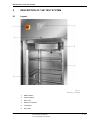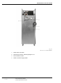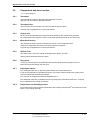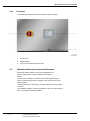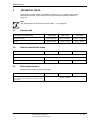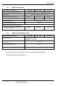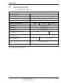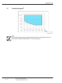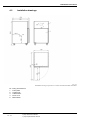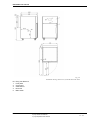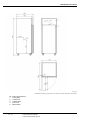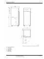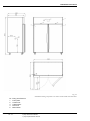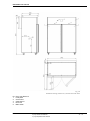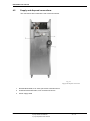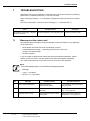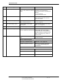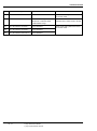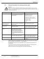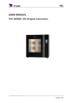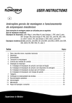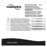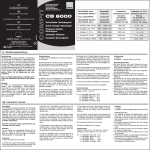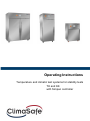
1
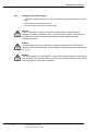
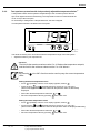
Operating Instructions Temperature and climatic test systems for stability tests TK and KK with Simpac controller This product line contains the following test system types. Climatic test systems KK 0028 KK 0057 KK 0130 Temperature test systems TK 2028 / 0028 TK 2057 / 0057 TK 2130 / 0130 The test systems are equipped with a Simpac controller. TABLE OF CONTENTS Table of contents INTRODUCTION CHAPTER 1 1.1 General information . . . . . . . . . . . . . . . . . . . . . . . . . . . . . . . . . . . . . . . . . . . . . . . . . . . 1 1.2 Finding your way around . . . . . . . . . . . . . . . . . . . . . . . . . . . . . . . . . . . . . . . . . . . . . . . 1 1.3 Warranty. . . . . . . . . . . . . . . . . . . . . . . . . . . . . . . . . . . . . . . . . . . . . . . . . . . . . . . . . . . . 2 1.4 1.3.1 Correct use . . . . . . . . . . . . . . . . . . . . . . . . . . . . . . . . . . . . . . . . . . . . . . . . . . . 2 1.3.2 Inadmissible and improper use . . . . . . . . . . . . . . . . . . . . . . . . . . . . . . . . . . . . 3 Safety . . . . . . . . . . . . . . . . . . . . . . . . . . . . . . . . . . . . . . . . . . . . . . . . . . . . . . . . . . . . . . 3 1.4.1 Definition of a specialist technician . . . . . . . . . . . . . . . . . . . . . . . . . . . . . . . . . 3 1.4.2 Safety instructions . . . . . . . . . . . . . . . . . . . . . . . . . . . . . . . . . . . . . . . . . . . . . . 4 1.4.3 Symbols on the test system. . . . . . . . . . . . . . . . . . . . . . . . . . . . . . . . . . . . . . . 6 1.4.4 Safety equipment. . . . . . . . . . . . . . . . . . . . . . . . . . . . . . . . . . . . . . . . . . . . . . . 6 DESCRIPTION CHAPTER 2 2.1 2.2 2.3 Layout. . . . . . . . . . . . . . . . . . . . . . . . . . . . . . . . . . . . . . . . . . . . . . . . . . . . . . . . . . . . . . 7 Components and their function . . . . . . . . . . . . . . . . . . . . . . . . . . . . . . . . . . . . . . . . . 9 2.2.1 Test space . . . . . . . . . . . . . . . . . . . . . . . . . . . . . . . . . . . . . . . . . . . . . . . . . . . 9 2.2.2 Test space door . . . . . . . . . . . . . . . . . . . . . . . . . . . . . . . . . . . . . . . . . . . . . . . 9 2.2.3 Control unit . . . . . . . . . . . . . . . . . . . . . . . . . . . . . . . . . . . . . . . . . . . . . . . . . . 9 2.2.4 Mechanical section . . . . . . . . . . . . . . . . . . . . . . . . . . . . . . . . . . . . . . . . . . . . 9 2.2.5 Rollers / Feet . . . . . . . . . . . . . . . . . . . . . . . . . . . . . . . . . . . . . . . . . . . . . . . . . 9 2.2.6 Entry ports . . . . . . . . . . . . . . . . . . . . . . . . . . . . . . . . . . . . . . . . . . . . . . . . . . . 9 2.2.7 Switchgear cabinet . . . . . . . . . . . . . . . . . . . . . . . . . . . . . . . . . . . . . . . . . . . . 9 2.2.8 Temperature and humidity sensors . . . . . . . . . . . . . . . . . . . . . . . . . . . . . . . . 9 2.2.9 Front plate . . . . . . . . . . . . . . . . . . . . . . . . . . . . . . . . . . . . . . . . . . . . . . . . . . . 10 Stainless steel and corrosive influences . . . . . . . . . . . . . . . . . . . . . . . . . . . . . . . . . . 10 TECHNICAL CHAPTER 3 OF THE TEST SYSTEM DATA 3.1 General data. . . . . . . . . . . . . . . . . . . . . . . . . . . . . . . . . . . . . . . . . . . . . . . . . . . . . . . . 11 3.2 Data for mechanical stress. . . . . . . . . . . . . . . . . . . . . . . . . . . . . . . . . . . . . . . . . . . . . 11 3.3 Noise measurement . . . . . . . . . . . . . . . . . . . . . . . . . . . . . . . . . . . . . . . . . . . . . . . . . . 11 3.4 Data for operation. . . . . . . . . . . . . . . . . . . . . . . . . . . . . . . . . . . . . . . . . . . . . . . . . . . . 12 3.5 Data for temperature tests . . . . . . . . . . . . . . . . . . . . . . . . . . . . . . . . . . . . . . . . . . . . . 12 3.6 Data for climatic tests2) . . . . . . . . . . . . . . . . . . . . . . . . . . . . . . . . . . . . . . . . . . . . . . . 13 3.7 Humidity diagram2) . . . . . . . . . . . . . . . . . . . . . . . . . . . . . . . . . . . . . . . . . . . . . . . . . . . 14 1) Option 2) only climatic test cabinets 3) only temperature test cabinets I – III TABLE OF CONTENTS PREPARING CHAPTER 4 4.1 Requirements for on-site installation and storage . . . . . . . . . . . . . . . . . . . . . . . . . . . 15 4.2 Installation drawings. . . . . . . . . . . . . . . . . . . . . . . . . . . . . . . . . . . . . . . . . . . . . . . . . . 16 4.3 Transporting the test system . . . . . . . . . . . . . . . . . . . . . . . . . . . . . . . . . . . . . . . . . . . 22 4.4 Installing the test system . . . . . . . . . . . . . . . . . . . . . . . . . . . . . . . . . . . . . . . . . . . . . . 22 4.5 4.6 feet1) ......................................... 22 Supply and disposal connections . . . . . . . . . . . . . . . . . . . . . . . . . . . . . . . . . . . . . . . . 23 4.5.1 Connecting the overflow/condensate drain . . . . . . . . . . . . . . . . . . . . . . . . . . 24 4.5.2 4.5.3 Connecting demineralised water2) . ................................ Setting up the power supply . . . . . . . . . . . . . . . . . . . . . . . . . . . . . . . . . . . . . 25 26 Checklist for initial startup . . . . . . . . . . . . . . . . . . . . . . . . . . . . . . . . . . . . . . . . . . . . . 27 4.4.1 Test cabinet with STARTUP CHAPTER 5 5.1 Activating the test system . . . . . . . . . . . . . . . . . . . . . . . . . . . . . . . . . . . . . . . . . . . . . 28 5.2 Corrosive influences through work in the test space . . . . . . . . . . . . . . . . . . . . . . . . . 28 5.3 Resetting safety temperature limiter . . . . . . . . . . . . . . . . . . . . . . . . . . . . . . . . . . . . . 28 5.4 Preparing the test specimen . . . . . . . . . . . . . . . . . . . . . . . . . . . . . . . . . . . . . . . . . . . 5.4.1 Selecting the test specimen. . . . . . . . . . . . . . . . . . . . . . . . . . . . . . . . . . . . . . 28 28 5.4.2 Corrosive influences of the test specimens . . . . . . . . . . . . . . . . . . . . . . . . . . 29 5.4.3 Heat-emitting test specimens . . . . . . . . . . . . . . . . . . . . . . . . . . . . . . . . . . . . 29 5.4.4 Energised test specimens . . . . . . . . . . . . . . . . . . . . . . . . . . . . . . . . . . . . . . . 29 5.5 Sealing the entry ports . . . . . . . . . . . . . . . . . . . . . . . . . . . . . . . . . . . . . . . . . . . . . . . . 30 5.6 Adjusting test specimen protection . . . . . . . . . . . . . . . . . . . . . . . . . . . . . . . . . . . . . . 5.6.1 Software temperature and humidity limiter . . . . . . . . . . . . . . . . . . . . . . . . . . 31 31 5.6.2 Test specimen protection with independently adjustable temperature limiter 32 User-specific functions, programming and operating modes . . . . . . . . . . . . . . . . . . . 5.7.1 Temperature tests in manual mode . . . . . . . . . . . . . . . . . . . . . . . . . . . . . . . . 34 34 Climatic test2) / stability test in the manual mode . . . . . . . . . . . . . . . . . . . . . Tolerance band monitoring . . . . . . . . . . . . . . . . . . . . . . . . . . . . . . . . . . . . . . 34 Checklist for startup . . . . . . . . . . . . . . . . . . . . . . . . . . . . . . . . . . . . . . . . . . . . . . . . . . 35 5.7 5.7.2 5.7.3 5.8 SHUTTING CHAPTER 6 II – III FOR STARTUP 34 DOWN 6.1 After each test . . . . . . . . . . . . . . . . . . . . . . . . . . . . . . . . . . . . . . . . . . . . . . . . . . . . . . 36 6.2 For longer shutdowns. . . . . . . . . . . . . . . . . . . . . . . . . . . . . . . . . . . . . . . . . . . . . . . . . 36 6.3 Final disposal of the test system . . . . . . . . . . . . . . . . . . . . . . . . . . . . . . . . . . . . . . . . 37 1) Option 2) only climatic test cabinets 3) only temperature test cabinets TABLE OF CONTENTS TROUBLESHOOTING CHAPTER 7 7.1 MAINTENANCE CHAPTER 8 8.1 General information . . . . . . . . . . . . . . . . . . . . . . . . . . . . . . . . . . . . . . . . . . . . . . . . . . 41 8.2 General information for cleaning stainless steel. . . . . . . . . . . . . . . . . . . . . . . . . . . . . 42 8.3 Consumables . . . . . . . . . . . . . . . . . . . . . . . . . . . . . . . . . . . . . . . . . . . . . . . . . . . . . . . 43 8.4 Maintenance schedules . . . . . . . . . . . . . . . . . . . . . . . . . . . . . . . . . . . . . . . . . . . . . . . 44 8.5 APPENDIX Messages on the control unit . . . . . . . . . . . . . . . . . . . . . . . . . . . . . . . . . . . . . . . . . . . 38 8.4.1 Maintenance schedule for specialist technicians. . . . . . . . . . . . . . . . . . . . . . 44 8.4.2 Maintenance schedule for operating personnel. . . . . . . . . . . . . . . . . . . . . . . 44 Maintenance work . . . . . . . . . . . . . . . . . . . . . . . . . . . . . . . . . . . . . . . . . . . . . . . . . . . 45 8.5.1 Cleaning the test space and installations . . . . . . . . . . . . . . . . . . . . . . . . . . . 45 8.5.2 Cleaning the test space door's seal . . . . . . . . . . . . . . . . . . . . . . . . . . . . . . . . 45 8.5.3 Cleaning the air-cooled condenser . . . . . . . . . . . . . . . . . . . . . . . . . . . . . . . . 46 8.5.4 Having the capacitive humidity measuring system 2) calibrated. . . . . . . . . . . 47 INDEX 1) Option 2) only climatic test cabinets 3) only temperature test cabinets III – III INTRODUCTION 1 INTRODUCTION 1.1 General information Read these operating instructions first to avoid malfunctions and any associated consequential damage! This operating manual provides you with all the necessary information and instructions for: – Installation – Operation – Mode of Operation – Malfunctions and troubleshooting 1.2 – Maintenance • Please observe the enclosed operating instructions for the control unit. • Please observe the operating instructions for the options in the Appendix. • Please observe all separate operating manuals. Finding your way around The symbols used in this operating manual have the following meaning. – Items in a list are indicated by a dash. • Instructions are indicated by a dot. Cross-references are indicated by an arrow. Explanation of the signal words and symbols used in this operating manual. DANGER Failure to comply with these instructions could endanger people, other living creatures or the environment. CAUTION Failure to comply with these instructions could cause damage to the test system or test specimen. NOTE This is used to indicate additional helpful information. 1) Option 2) only climatic test cabinets 3) only temperature test cabinets 1 - 47 INTRODUCTION 1.3 Warranty – The design of the test system as supplied by us must not be altered. – The warranty shall be void if you fail to comply with the stipulations of these operating instructions. – The test system has been designed, manufactured and inspected before delivery with all due care in accordance with the EC directives as per the enclosed declaration of conformity. – The test system meets the standards for conducted and emitted interference specified in the declaration of conformity. – The safety of testing cabinet is possible only if the necessary repairs are carried out by our service center or an authorised professional. – The work specified in the maintenance schedule (page 44) may only be carried out by the people specified therein. – Only genuine OEM parts may be used in maintenance and repair work. – With regard to translated versions, the specifications and statements of the Dutch operating instructions are binding. 1.3.1 Correct use The test system has been specially designed and constructed for testing the stability of various materials and parts. You can perform tests which can examine the effects of temperature and humidity2) on various materials and parts. You can carry out other tests with a constant environment2) - refer to the technical data 3 (page 11). The test system is designed for unsupervised operation. It is equipped with appropriate safety devices that stop the operation in the event of safety-critical faults. 1.4.4 Safety equipment (page 6) 2 - 47 1) Option 2) only climatic test cabinets 3) only temperature test cabinets INTRODUCTION 1.3.2 Inadmissible and improper use DANGER Inadmissible and improper use means, for example: – Placing inflammable, explosive, toxic or corrosive substances in the test system, or placing them so close to the test system that this could represent a danger – Placing substances which become potentially hazardous when exposed to the temperature range of the test system, in the test system or sufficiently close to it to represent a danger – Placing substances that could become explosive in contact with air inside or hazardously near the test system – Endangering living beings by allowing them into the test system – Using the test cabinet for heating and storing food for the purpose of consumption 1.4 Safety DANGER The following basic rules must be strictly observed! Failure to comply may present a danger to life and limb of the operating personnel or third parties, or result in the destruction of the test specimen or the test system. • Do not remove any safety covers. • Do not disable any safety devices. • Do not tamper with any safety devices. Such modifications can be especially dangerous for the operating personnel, since they may have no knowledge of the alteration and rely on the test system's safety. 1.4.1 Definition of a specialist technician A specialist technician is a person who, due to his/her training and experience, is capable of avoiding potential hazards relating to electricity and the refrigerating unit. 1) Option 2) only climatic test cabinets 3) only temperature test cabinets 3 - 47 INTRODUCTION 1.4.2 Safety instructions DANGER – The test system is only to be operated by trained personnel. – The operating company must prepare appropriate operating procedures on the basis of these operating instructions. These operating procedures must take the relevant local and internal conditions into account, as well as the language of the operating personnel. – The user must ensure that all personnel working with the test system know and observe the safety instructions. – Work on electrical equipment and on the refrigeration system must be carried out by our service center or our authorized personnel. The necessary documents can be found in the documentation of the test cabinet and may only be used by these individuals. – EN 378-4 Appendix D.6 specifies an annual inspection of the pressure switch that limits the pressure. This must only be carried out by our service center or an authorized specialist. – The user must ensure that the directions regarding installation and operation of refrigerating units as per EN 378-1 Chap. 4.2, EN 378-3 Chap. 5 and Appendix A, EN 378-4 Chaps. 4, 5 and 6, and national directives (e.g. for Germany the BetrSichV (Health and Safety at Work Regulations)) are duly observed. – Have the separately-adjustable tmin / tmax temperature limiter1) checked annually. The actual value display of the temperature limiter must agree with the actual value in the test space, and the temperature limiter must be triggered when the limits are exceeded, as described in Chapter 5.6.2 (page 34). • First read the operating instructions for the control unit. • Keep the operating instructions near the test system. • In addition to the instructions in this operating manual, the relevant national laws, regulations and directives must be observed when installing and operating the test system. • When introducing a test specimen which has electrical wiring, ensure that the local and/or national safety rules are observed. This especially applies with regard to equipotential bonding for leakage currents that may be caused by a test specimen. If leakage currents > 16 A are able to occur, you must provide an external equipotential bonding conductor for the test space. • Ensure that heat-emitting or activated test specimens are never present in the test system when it is switched off, otherwise there is a fire hazard. The test space is only protected against excess temperature when the test system is switched on. 5.4.3 (page 29) and 5.4.4 (page 29) • Ensure that the separately adjustable tmin / tmax temperature limiter1) is set correctly for the material you are testing. • Before closing the test space door, make sure that no one is inside the test space. • Take the test system out of operation immediately when components or lines are damaged. Ensure that the test system is not put back into operation until the defects have been rectified. • If working in the vicinity of fans, cover long hair with a cap, a hairnet or similar head covering. • You will need demineralised water for climatic operation2). You must never drink this water. Risk of poisoning. 4 - 47 1) Option 2) only climatic test cabinets 3) only temperature test cabinets INTRODUCTION Installation, servicing and maintenance You must observe the following instructions when installing, servicing and performing maintenance work: • Bring the test space to ambient temperature; set the appropriate nominal value for this purpose • Set the master switch to »O, OFF« • Padlock the master switch against being switched on accidentally • Provide a safety clearance of at least 500 mm between test cabinet and wall as an escape route • Remove the key of the test space door • Do not use sharp-edged tools • Wear safety gloves • Wear safety shoes • Depending on the size of the test cabinet, when carrying out installation and maintenance work, you must move unwieldy parts (e.g. cover plates). Use appropriate equipment! Using the entry ports • Observe the safety regulations for electrical equipment, e.g. IEC 60364-4-41, VDE 0100 Part 410 and EN 60204 Part 1, as well as the applicable accident prevention regulations. • Use only temperature and climate-resistant cables. • Seal the entry ports which are being used with temperature-resistant and environment-resistant material. • Seal the entry ports which are not being used by means of the plugs provided. Refrigerant The refrigerant used ( type plate) belongs to the Group A1 according to EN 378-1. It has low toxicity. It has no negative impacts on most people. It is not combustible and does not spread flames. Refrigerants are heavier than air and therefore build up on the floor. • Should refrigerants be released, please notify our service center or a specialist technician authorised by us and make sure that the installation site is well ventilated. • Observe the safety data sheet in the documentation of the test cabinet. 1) Option 2) only climatic test cabinets 3) only temperature test cabinets 5 - 47 INTRODUCTION 1.4.3 Symbols on the test system • Note the symbols attached to the test system which have the following meaning: OPERATING INSTRUCTIONS AND SAFETY INFORMATION • Read the operating instructions prior to startup! • Observe the safety information during operation! WARNING – HAZARD AREAS • Observe the danger warnings in the operating instructions WARNING – DANGEROUS ELECTRICAL VOLTAGE Work on this equipment may only be performed by a specialist electrician. • Set the master switch to »O, OFF«. WARNING – HOT SURFACES 2) The steam humidifier and the parts coming into contact with it may be very hot. • Wear protective clothing (safety gloves, face protection)! WARNING – REMOVE POWER Behind these covers there are parts under power. . 1.4.4 Remove power plug from power supply socket before opening this panel. Safety equipment The test system is equipped with the following safety devices: Test specimen, test cabinet and environment safeguards – Safety temperature limiter »TEH100« for protection against excess temperatures in the test space. – Independently adjustable temperature limiters tmin / tmax 1) for protection against thermal overstressing of the test specimen. – Temperature and humidity limiter software for protection against excess and low temperatures in the test space – Dry contact as an alarm output for connecting to an on-site monitoring system, X2, Max 0,5A. - The humidifier is protected against overheating by a thermostat, TEH800. This thermostat is located on the humidifier at the back of the unit. High pressure in the refrigerating unit – Pressure switch for protection against excessive overpressure in the refrigerating unit, PEH300 DANGER The safety devices only work when the test system is switched on. The test system may be equipped with options and additional accessories. These descriptions and the necessary safety precautions are in the appendix. 6 - 47 1) Option 2) only climatic test cabinets 3) only temperature test cabinets DESCRIPTION OF THE TEST SYSTEM 2 DESCRIPTION OF THE TEST SYSTEM 2.1 Layout Fig. 2-1 Front view, test cabinet 1 Master Switch 2 Control Display 3 Door Lock 4 Mechanical section 5 Test Space 6 Entry Port 1) Option 2) only climatic test cabinets 3) only temperature test cabinets 7 - 47 DESCRIPTION OF THE TEST SYSTEM Fig. 2-2 Rear view, test cabinet KK 0057 8 - 47 1 Water drain connection 2 Electrical connection, cable length approx. 5 m 3 Documentation holder 4 Water connection supply water 1) Option 2) only climatic test cabinets 3) only temperature test cabinets DESCRIPTION OF THE TEST SYSTEM 2.2 Components and their function 2.1 Layout (page 7) 2.2.1 Test space The test cabinet is made of high gloss stainless steel. The test specimen can be stored on the insert shelves. 2.2.2 Test space door The test space door is lockable. The lock is located on the front plate. A special key is supplied for the closing mechanism. 2.2.3 Control unit All the control and operating commands can be activated on the control unit by pressing the respective function symbols. There is a separate operating manual for the control unit. 2.2.4 Mechanical section The mechanical section can be accessed from the top. The mechanical section contains the equipment necessary for producing the test conditions. A special key is supplied for the closing mechanism. 2.2.5 Rollers / Feet The basic version of the test cabinet is equipped with castors. The test cabinet can be fitted with feet as an option. 2.2.6 Entry ports Lines (e.g. measuring lines for qualification and monitoring) and testing equipment can be laid in the test space through the entry port. 2.2.7 Switchgear cabinet The switchgear cabinet is on the test system besides the mechanical section. It may only be opened by a specialist electrician. The control cabinet contains the system fuses, control modules and electrical components. The controller is designed according to EN 60204 Part 1. The switchgear cabinet is accessible from the top through the removable metal cover. A special key is supplied for the closing mechanism. 2.2.8 Temperature and humidity sensors The measurement sensors used for temperature and humidity measurement2) are located in the test space, in the cooling assembly. 1) Option 2) only climatic test cabinets 3) only temperature test cabinets 9 - 47 DESCRIPTION OF THE TEST SYSTEM 2.2.9 Front plate The following component parts are located on the front plate. Fig. 2-3 Front plate 2.3 1 Control unit 2 Master Switch 3 Lock for locking the test space door Stainless steel and corrosive influences Rust-proof stainless steel is a product designation for a group of particularly corrosion-resistant and hygienic steels. The corrosion resistance is based on an invisible passive layer, which is formed by the entry of oxygen in the air and which heals itself if injured. If this passive layer is injured (e.g. through soiling), this may result in corrosion. The following chapters contain information on how you can keep the risk of corrosion as small as possible. 10 - 47 1) Option 2) only climatic test cabinets 3) only temperature test cabinets TECHNICAL DATA 3 TECHNICAL DATA All the data is average values of standard test cabinets at +25 °C ambient temperature, without test specimens, without options and a nominal voltage as stated in Chapter 3.4 (page 12). NOTE The dimensions can be found in the floor plan. 4.1 (page 16) 3.1 General data Test cabinets for stability tests Test space volume approx. 205 litres Weight 3.2 2028 / 0028 approx. 130 kg 2057 / 0057 2130 / 0130 approx. 505 litres approx. 1110 litres approx. 140 kg approx. 220 kg Data for mechanical stress Test cabinets for stability tests 2028 / 0028 2057 / 0057 2130 / 0130 Maximum load (evenly distributed over the entire surface) on each insert shelf 30 kg total shelf load 3.3 200 kg 250 kg 250 kg 2057 / 0057 2130 / 0130 Noise measurement We specify the measuring method separately. Test cabinets for stability tests 2028 / 0028 Sound pressure level Free-field measurement at a distance of 1 m from the front and 1.6 m in height 1) Option 2) only climatic test cabinets 3) only temperature test cabinets approx. 51 dB(A) 11 - 47 TECHNICAL DATA 3.4 Data for operation Test cabinets for stability tests 2028 / 0028 Emitted interference; interference immunity Standards complied with see declaration of conformity Voltage rating 2057 / 0057 2130 / 0130 1/N / PE AC 220/230 V +6% -10% 50Hz Power rating (Temp / Climat) (kW) 1.6/1.1/1.4 On-site fuse protection 1.6/1.1/1.4 2.2/1.7/2.0 16 A slow-blow Protection type control cabinet IP 20 Heat dissipation of air-cooled test systems mean heat dissipation to surroundings (kW) 0,8/0,6/0,7 0,8/0,6/0,7 1,1/0,8/1,0 at a constant +25 °C / 60% RH 3.5 Data for temperature tests Test cabinets for stability tests Temperature range* 2028 / 0028 2057 / 0057 models 2XXX -20 °C to 60°C models 0XXX +0 °C to 60°C Temperature homogeneity in space ** relative to the setpoint Temperature deviation in time ** ± 0.7K ± 0.5K * 0-5°C not for continues operation due to ice building on the evaporator. ** 5-50°C according to IEC 60068-3-5. 12 - 47 1) Option 2) only climatic test cabinets 3) only temperature test cabinets 2130 / 0130 TECHNICAL DATA 3.6 Data for climatic tests2) 3.7 Humidity diagram2) (page 14) General data for the humidification system Water reservoir volum1) 25 ltr Water quality Demineralised pH value 6 to 7 Conductivity 5 to 20 µS/cm Test cabinets for stability tests 0028 0057 Temperature range 0130 +15 °C to +50 °C Humidity range 30% RH to 90% RH Dew point range +10 °C to +48°C Temperature homogeneity in space ** ± 0.7K relative to the setpoint Temperature deviation in time ** ± 0.7K ± 0.5K at centre of useable space Humidity deviation over time ** ± 1 to ± 3% RH at centre of useable space Humidity water usage ± 1% RH to ± 3% RH approx. 0.6l / 24h at constant +25 °C / 60% RH ** according to IEC 60068-3-5. 1) Option 2) only climatic test cabinets 3) only temperature test cabinets 13 - 47 TECHNICAL DATA 3.7 Humidity diagram2) Fig. 3-1 Humidity range NOTE The humidity range may be greater than that shown in the diagram due to the introduction of dried compressed air1) into the test space. 14 - 47 1) Option 2) only climatic test cabinets 3) only temperature test cabinets PREPARING FOR STARTUP 4 PREPARING FOR STARTUP 4.1 Requirements for on-site installation and storage The test cabinet may be operated in residential areas, because it meets interference requirements according to EN 61000-6-3 Declaration of conformity. Ensure that the test system installation site meets the following requirements: – The room volume must be at least 2.5 m 3 per kg of refrigerant. (Refrigerant Rating plate) – if open flames or similarly hot surfaces are used at the installation site, adequate ventilation must be provided due to potential leaks and decomposition products caused by refrigerants – Take care with smoke detectors in the area (check setting) It is possible that, for example in appropriate tests (high temperature and moisture) or on account of the test specimen, that clouds of vapour may occur. – Max. contamination level 2 in accordance with EN 50178 – Altitude max. 1000 m above mean sea level – No direct sunlight – Avoid installing in the vicinity of heat sources – Avoid installing in the vicinity of hazardous materials 1.3.2 Inadmissible and improper use (page 3) – Permissible ambient temperature during operation: +18 °C to +35 °C – Permissible ambient temperature for storage -25 °C to +55 °C – relative humidity max. 75%, non-condensing Requirements for the floor – The floor must be able to bear the weight of the test system 3.1 (page 11) and the test specimen 3.2 (page 11). – The floor must be level and horizontal. Slight unevenness can be compensated by adjusting the feet1). Space requirements • The space requirements are specified in the following installation drawings. 1) Option 2) only climatic test cabinets 3) only temperature test cabinets 15 - 47 PREPARING FOR STARTUP 4.2 Installation drawings Fig. 4-1 Installation drawing temperature test cabinet TK 2028 and 0028 with rollers R1 1 2 3 4 5 16 - 47 Entry port Ø 50 mm Front plate Control unit Cabinet door Door lock Main switch 1) Option 2) only climatic test cabinets 3) only temperature test cabinets PREPARING FOR STARTUP Fig. 4-2 Installation drawing climatic test system KK 0028 with rollers R1 1 2 3 4 5 Entry port Ø 50 mm Front plate Control unit Cabinet door Door lock Main switch 1) Option 2) only climatic test cabinets 3) only temperature test cabinets 17 - 47 PREPARING FOR STARTUP Fig. 4-3 Installation drawing temperature test cabinet TK 2057 and 0057 with rollers R1 1 2 3 4 5 Entry port Ø 50 mm Front plate Control unit Cabinet door Door lock Main switch 18 - 47 1) Option 2) only climatic test cabinets 3) only temperature test cabinets PREPARING FOR STARTUP Fig. 4-4 Installation drawing climatic test system KK 0057 with rollers R1 1 2 3 4 5 Entry port Ø 50 mm Front plate Control unit Cabinet door Door lock Main switch 1) Option 2) only climatic test cabinets 3) only temperature test cabinets 19 - 47 PREPARING FOR STARTUP Fig. 4-5 Installation drawing temperature test cabinet TK 2130 and 0130 with rollers R1 1 2 3 4 5 Entry port Ø 50 mm Front plate Control unit Cabinet door Door lock Main switch 20 - 47 1) Option 2) only climatic test cabinets 3) only temperature test cabinets PREPARING FOR STARTUP Fig. 4-6 Installation drawing climatic test system KK 0130 with rollers R1 1 2 3 4 5 Entry port Ø 50 mm Front plate Control unit Cabinet door Door lock Main switch 1) Option 2) only climatic test cabinets 3) only temperature test cabinets 21 - 47 PREPARING FOR STARTUP 4.3 Transporting the test system To transport the test system, you will need a forklift or a comparable lifting vehicle with an adjustable fork width. CAUTION Do not apply straps. You can lift the test system from any side if the fork is long enough to support the entire depth and width of the test system. 4.4 • Position the fork under the test system (Mind the wheels if pallet is not present) • Adjust the fork width • Raise the test cabinet by approx. 50 mm • Transport the test cabinet to the planned erection location and erect it according to the installation drawing • Remove packaging (and pallet) and dispose of properly Installing the test system DANGER When installing the mobile version of the test cabinet, place it on a horizontal floor and actuate the wheel stop (only rollers on the front side have a wheel stop) so that the test cabinet does not roll away. 4.4.1 Test cabinet with feet1) • Lift test system with lifting vehicle • Align the test cabinet using a spirit level by turning the feet1) The gap between the doors (test cabinets model 0130 and 2130 l) must be the same everywhere. 22 - 47 1) Option 2) only climatic test cabinets 3) only temperature test cabinets PREPARING FOR STARTUP 4.5 Supply and disposal connections The connections are located at the rear of the test cabinet. Fig. 4-7 Supply and disposal connections 1 Demineralised water, max. 5 bar, quick hose connection 6 mm. 2 Overflow/condensate drain, hose connection Ø 16 mm 3 Power supply cable 1) Option 2) only climatic test cabinets 3) only temperature test cabinets 23 - 47 PREPARING FOR STARTUP 4.5.1 Connecting the overflow/condensate drain Connect the line as follows: • Connect to the overflow/condensate drain of the test cabinet Fig. 4-7 (page 23) • Secure the hose with a hose clamp • Route the hose into an on-site floor outlet without pressure and without bending it CAUTION If the overflow/condensate drain is not connected, the water in the system will run into the area of installation. • If you do not have a floor drain, capture the water in a sufficiently dimensioned container or install a water-uptake unit. • Monitor the fill level of this container and the functioning of the water-uptake unit. There is no monitoring at the plant. NOTE We recommend that you install a water sensor device under the overflow/condensate drain as a protection against inadvertent leakage of water. Appropriate safety systems are available at specialist shops. 24 - 47 1) Option 2) only climatic test cabinets 3) only temperature test cabinets PREPARING FOR STARTUP 4.5.2 Connecting demineralised water2) Water quality for humidifying water 3.6 (page 13) Connect the line as follows: • Connect the network with demineralised water or dimineralisation unit1) using a pressure-resistant hose Fig. 4-7 (page 23) • Connect the 6 mm tube by pushing the hose in the quick connector The maximum permissible water pressure is 6 bar. The minimum permissible water pressure is 1 bar. CAUTION Ensure that the overflow/condensate drain is connected to an on-site floor outlet to prevent water damage in case of a leaky float valve in the reservoir. CAUTION We recommend that you install a water stop or sensor device in the humidifying water supply line as a protection against inadvertent water damage. Such safety systems are available at specialist shops. 1) Option 2) only climatic test cabinets 3) only temperature test cabinets 25 - 47 PREPARING FOR STARTUP 4.5.3 Setting up the power supply – The mains voltage and frequency must correspond to the specifications on the rating plate – Mains fuse must be of sufficient size • Connect the test system to the power supply CAUTION If the on-site mains voltage and frequency differ from the specifications in Chapter 3.4 Data for operation (page 16), have the test system connected by a specialist technician in accordance with the enclosed »Special Voltage« installation manual. DANGER An earthed-lead system for the power supply in accordance with EN 60204-1, Chapter 18.2 must be available. The test system's earthed-lead system resistance is < 0.1 DANGER The loop impedance, per EN 60204, of the mains supply must be low enough at the transition point (socket outlet), so that the upstream protective device (fuse) can be triggered in the event of damage. 26 - 47 1) Option 2) only climatic test cabinets 3) only temperature test cabinets PREPARING FOR STARTUP 4.6 Checklist for initial startup • Make sure that the following requirements for startup have been met: – Does the installation site meet the requirements? 4.1 (page 15) – Does the test cabinet stand horizontally and has the wheel stop been actuated? 4.4 (page 22) – Are the supply and discharge connections set up correctly? 4.5 (page 23) – Are the hose connections fixed to the test cabinet? – Do the cooling water and humidification water comply with our specifications? 3.6 (page 13) – Does the electrical data of the mains supply comply with our specifications? 3.4 (page 12) 1) Option 2) only climatic test cabinets 3) only temperature test cabinets 27 - 47 STARTUP 5 STARTUP 5.1 Activating the test system CAUTION The ambient temperatures may be different in case of change of location. Condensate may form in and on the test cabinet. Do not switch the main switch before the test cabinet has adjusted to the current ambient temperatures, otherwise the test cabinet may be damaged due to shortfall below the dew point. • 5.2 Set the master switch to »I ON« Corrosive influences through work in the test space Note that when working in the test space, any objects (e.g. shoes, packaging, tools) entering the test space will leave dirt (e.g. salt, outside rust) on the stainless steel and thus increase the risk of corrosion. • Remove these dirt particles immediately using a cleaning agent or similar, according to our specifications 8.2 (page 42). 5.3 Resetting safety temperature limiter The safety temperature limiter »TEH100« may trip due to overheating. In this case, the message »Temp. limiter testchamber**« is displayed on the control unit. The temperature limiter is located besides the electrical panel and will reset automatically after the temperature has gone down. 5.4 Preparing the test specimen 5.4.1 Selecting the test specimen You can store the test specimens on the insert shelves. Try to distribute the test specimen as evenly as possible over the entire area. • Make sure that the test specimen corresponds to intended usage in relation to the following points: – Characteristics 1.3.1 (page 2) – Corrosive effects 5.4.2 (page 28) – Weight 3.1 (page 11) – Thermal effects 1.4.2 (page 4) 28 - 47 1) Option 2) only climatic test cabinets 3) only temperature test cabinets STARTUP 5.4.2 Corrosive influences of the test specimens At high temperatures and humidity, test specimens may release harmful substances. These harmful substances lead to corrosion and damage the test space. Regular cleaning of the test space, fresh humidification water and a clean water reservoir prevent such damage. Corrosion is mainly caused by: – Chlorine compounds – Acids – Alkaline solutions CAUTION Test specimens, plastics (e.g. PVC cables) or mounted and unwashed PCBs can release chlorine or other hazardous substances. When working with such test material, you should always talk to our service center about appropriate precautions. 5.4.3 Heat-emitting test specimens You can conduct tests involving heat-emitting test specimens. Permissible heat emission depends on the size of the test system and the actual test space temperatures. • Observe the instructions for permissible heat compensation 3.4 (page 12) CAUTION When the test system is in the pause/stop mode or switched off, the cooling system is no longer effective. Heat-emitting test specimens would heat up the test space to inadmissible levels. In this case, make sure that heat-emitting test specimens are deactivated otherwise there is a fire hazard. 5.4.4 Energised test specimens In the case of an energised test specimen with an external power supply, dangerous voltage may be constantly present in the test specimen. • Before handling energised test specimens, be sure that the test system and onsite voltage supply are disconnected. • Observe the appropriate safety regulations for your test specimen. 1) Option 2) only climatic test cabinets 3) only temperature test cabinets 29 - 47 STARTUP 5.5 Sealing the entry ports • Observe the safety instructions 1.4.2 »Using the entry ports« (page 4). NOTE Open entry ports cause high water consumption2) during climatic tests. Avoid extreme climatic values2). Low test space temperatures may cause the evaporator to ice up. • Close the entry ports with a closed plug, if the entry port is not being used. Fig. 5-2 Closed sealing plug • Seal the entry ports which are being used with temperature-resistant and environment-resistant material. 30 - 47 1) Option 2) only climatic test cabinets 3) only temperature test cabinets STARTUP 5.6 Adjusting test specimen protection 5.6.1 Software temperature and humidity limiter The test system's controller is equipped with a software temperature and humidity limiter. This device can be used to set alarm and warning limits for the maximum and minimum permissible temperature and humidity values. If no limits are set, the test system automatically uses the limits of the previous test. Set the limits Operating manual for the control unit, Chapter »Basic menu« On exceeding the warning limits, the message »Warn limit temp.*« or »Warn limit humidity*« is displayed at the control unit. On exceeding the alarm limits, the message »Software specimen protection**« or. »Humidity out of range*« is displayed at the control unit and the test is stopped. CAUTION On starting a test, always ensure that the lower limit is below the actual test space temperature and the upper limit above the actual test space temperature. The limits must be at least 5 K higher/lower than the respective nominal values. • Adjust the limits according to the sensitivity of the test specimen. 1) Option 2) only climatic test cabinets 3) only temperature test cabinets 31 - 47 STARTUP 5.6.2 Test specimen protection with independently adjustable temperature limiter1) A temperature limiter which operates independently of the controller protects the test spe-cimen against thermal overstressing. The temperature sensor is located behind the cover on top of the test space. On exceeding or falling below a temperature limit, the test is stopped. The temperature limiter is located on the front plate. Fig. 5-3 Temperature limiter The limits are factory-set in accordance with the temperature range of the test system. • Adjust the limits to your requirements. CAUTION The limit for the maximum value must be 5 to 10 K above the temperature setpoint, and the limit for the minimum value must be 5 to 10 K below it. NOTE By pressing value. , the »INP« function can be used to query the current temperature Setting maximum temperature value • Press repeatedly until the »AH« display appears, release • Press the keys and simultaneously for more than 3 s, until »AH« (Alarm limit High) and the current maximum temperature value are alternately displayed • Select the desired temperature value with • Save the temperature value by pressing or twice within 30 s Setting minimum temperature value 32 - 47 • Press repeatedly until the »AH« display appears, release • Press the keys and simultaneously for more than 3 s, until »AL« (Alarm limit Low) and the current minimum temperature value are displayed alternately • Select the desired temperature value with • Save the temperature value by pressing 1) Option 2) only climatic test cabinets 3) only temperature test cabinets or twice within 30 s STARTUP If the limits are exceeded, the respective indicator light (»MIN« / »MAX«) on the temperature limiter lights up and the control unit displays the message »Thermal specimen protection**«. • Increase/decrease the limit by 5 to 10 K, or open the test space door until the temperature in the test space is back within the permissible temperature range • Keep depressed for approx. 3 s; the indicator light goes out • Acknowledge the message Operating manual for the control unit, Chapter »Troubleshooting« If the temperature limiter is flashing and »1999« is displayed, there is a short circuit or the sensor is broken. The message »Thermal specimen protection**« appears on the control unit 1) Option 2) only climatic test cabinets 3) only temperature test cabinets 33 - 47 STARTUP 5.7 User-specific functions, programming and operating modes Tests can be run in the manual/program mode. • You can read more about this in the operating instructions for the control unit. NOTE When starting a test, the control unit displays the question asking whether you have set the test specimen protection properly 5.6.2 (page 32). 5.7.1 Temperature tests in manual mode Operating manual for the control unit, Chapter »Operating menu« Make the settings as follows. 5.7.2 • Set the nominal temperature value • Set the humidity setpoint to »0.0 % RH«2) • Starting the test Climatic test2) / stability test in the manual mode Operating manual for the control unit, Chapter »Operating menu« Make the settings as follows. 5.7.3 • Set the nominal temperature value • Set nominal humidity value • Starting the test Tolerance band monitoring The test system is equipped with tolerance band monitoring. Tolerances are factory-set at ± 2 K for temperature and ± 5% RH for humidity. They can be changed. • Set the tolerances Operating manual for the control unit, Chapter »Basic menu« Monitoring begins automatically 10 min after the tolerance band is reached. If the actual value is outside the tolerance band for longer than 15 minutes, the message »Tolerance temp.*« or »Tolerance humidity*« is displayed on the control unit. 34 - 47 1) Option 2) only climatic test cabinets 3) only temperature test cabinets STARTUP 5.8 Checklist for startup • Make sure that the following requirements for startup have been met: – Is the system connected to the demineralized water system? 4.5.2 (page 25) – Is the test specimen suitable for the planned test? 5.4 (page 28) – In the case of a heat-emitting test specimen, are you sure that the specimen was deactivated? 5.4.3 (page 29) – Has the disconnection of the power supply for energised test specimens been ensured? 5.4.4 (page 29) – Have the limits for the software temperature and humidity limiter been set correctly? 5.6.1 (page 31) – Has the independently adjustable temperature limiter been set correctly? 1) 5.6.2 (page 32) – Are the entry ports closed? 5.5 (page 30) – Has all the maintenance work required during the test period been performed? 8.4 (page 44) – Have all the options been installed properly? 1) Option 2) only climatic test cabinets 3) only temperature test cabinets 35 - 47 SHUTTING DOWN 6 SHUTTING DOWN Depending on the nature and duration of the shutdown, the following items must be observed: 6.1 After each test • Bring the test space to ambient temperature; set the appropriate nominal value for this purpose 6.2 • End test • Shut down on-site systems • Shut down optional equipment • Opening the test space door • Remove the test specimen from the test space • Clean and dry the test space For longer shutdowns If you shut the test system down for a prolonged period, or move it to a location where there is a danger of frost, the following measures must be carried out: 36 - 47 • Carry out all work steps according to Chapter 6.1 After each test (page 36) • Set the master switch to »O OFF« • Pull the mains plug • Leave the test space door open a crack so that the test space can dry out • Close the demineralized water connection. 1) Option 2) only climatic test cabinets 3) only temperature test cabinets SHUTTING DOWN 6.3 Final disposal of the test system If you do not wish to dispose of the test cabinet yourself, then please contact our service center. For a fee, we will make sure that the unit is disposed of appropriately and with minimal impact on the environment. If you dispose of the test system yourself, proceed as follows: DANGER Dispose of the following materials as hazardous waste. Forward them to the appropriate disposal points. – Refrigerant – Compressor oil – Electrical components DANGER • Destroy the door lock; otherwise persons may become trapped! The national and local waste disposal requirements valid at the time of disposal must be observed. 1) Option 2) only climatic test cabinets 3) only temperature test cabinets 37 - 47 TROUBLESHOOTING 7 TROUBLESHOOTING Depending on the type of malfunction, troubleshooting can be performed by the operating personnel, by a specialist technician, or our service center. When a warning message ( 7.1 indicated by *) appears, the test will continue on a limited basis. The test is interrupted in case of an alarm message ( 7.1 indicated with **). Fault Possible causes Temperature and humidity2) setpoints cannot be achieved Too little refrigerant in the refrigerating unit 7.1 Correction Contact our service center Messages on the control unit The following alarm messages, warning messages or other information can be displayed on the control unit. • Eliminate the cause with the aid of the following overview • Acknowledge the message Operating manual for the control unit, Chapter »Troubleshooting« • Resume operation If you are unable to eliminate the malfunction using the measures listed here, please contact our service center. This also applies if the same faults appear repeatedly. The contact information for our service center can be found in the Appendix. NOTE To ensure speedy service, we need the following particulars – Message – Type ( type plate) – Device no. ( type plate) No. Message Possible causes Corrective measure 3 Temp. limiter testchamber** Temperature limiter »TEH100« has tripped 5.3 Resetting safety temperature limiter (page 28) 5 Software specimen protection** Actual temperature value outside alarm limit Adjust temperature setpoint and alarm limit 5.6.1 (page 31) 6 Warn limit temp.* (if set) Actual temperature value outside warning limit Adjust temperature setpoint and warning limit 5.6.1 (page 31) 38 - 47 1) Option 2) only climatic test cabinets 3) only temperature test cabinets TROUBLESHOOTING No. Message Possible causes Corrective measure 8 Tolerance temp.* (if set) Actual temperature value longer than 15 min outside the tolerance band Close the test space door, clean the condenser, check whether the temperature deviation is permitted for the test 5.7.3 (page 34) Contact our service center 15 Door not closed* Test space door is open. The test space fan stops immediately. Close the test space door, the test space fan restarts. 17 Humidity out of range*(if set) Humidity actual value longer than 5 min outside alarm limit Adjust humidity setpoint and alarm limit 5.6.1 (page 31) 25 Warn limit humidity* (if set) Actual humidity value outside warning limit Adjust humidity setpoint and warning limit 5.6.1 (page 31) 26 Temp. limiter steam humidifier** Malfunctioning steam humidifier Contact our service center 27 Tolerance humidity* (if set) Actual humidity value longer than 15 min outside the tolerance band Close the test space door, check the water supply, clean the overflow/ condensate drain, check whether the humidity deviation is permitted for the test, 5.7.3 (page 34), contact our service center 34 High pressure compr. PC** High pressure in the refrigerating unit Switch off the test system and contact our service center For air-cooled test system Fins of the condenser fouled Clean fins 8.5.3 (page 46) Ambient temperature too high Make sure of ambient temperature 4.1 (page 15) according to our specifications 1) Option 2) only climatic test cabinets 3) only temperature test cabinets 39 - 47 TROUBLESHOOTING No. Message Possible causes Corrective measure 206 a) CPU-Error: Overload** Controller is overloaded Switch off the test system and contact our service center 216 Powerfail** Power failure during a test, mains failure time or tolerance band outside defined range Check values for mains failure time and tolerance band, continue test or re-start 217 Act. value defect: CPU/X21** Sensor defective Switch off the test system and contact our service center 218 Act. value defect: CPU/X22** Sensor defective 219 Act. value defect: DAIO1/X31** Sensor defective a) Internal controller messages, they cannot be checked in the course of a qualification. 40 - 47 1) Option 2) only climatic test cabinets 3) only temperature test cabinets M AINTENANCE 8 8.1 MAINTENANCE General information Regular care and maintenance are essential for optimum operation and long service life of the test system. The work specified in the maintenance schedule (page 44) may only be carried out by the people specified therein. Proper performance of this work is not a substitute for the professional maintenance carried out by our service center. A maintenance contract with our service center specifies, among other things, intervals at which a member of our customer service team will come to your location and check the refrigerating unit, the electrical equipment and the safety equipment. The contact information for our service center can be found in the Appendix. CAUTION EN 378-4 Appendix D.6 specifies an annual inspection of the pressure switch that limits the pressure. This must only be carried out by our service center or an authorized specialist. CAUTION Have the independently adjustable tmin / tmax temperature limiter1) checked annually. The actual value display of the temperature limiter must agree with the actual value in the test space, and the temperature limiter must be triggered when the limits are exceeded, as described in Chapter 5.6.2 (page 32). DANGER Work on electrical equipment and on the refrigeration system must be carried out by our service center or our authorized personnel. The necessary documents can be found in the documentation of the test cabinet and may only be used by these individuals. • Contact our service center. We will dispatch a specialist technician who will perform the maintenance work. Or we can supply you with a list of specialist technicians who are authorised to perform the maintenance work. Our service center has the technical facilities required for expert disposal of the waste material resulting from servicing. On request, we can take this material back for a fee. 1) Option 2) only climatic test cabinets 3) only temperature test cabinets 41 - 47 M AINTENANCE 8.2 General information for cleaning stainless steel CAUTION Keep to the following instruction when cleaning stainless steel, in order to avoid corrosion. Use only cleaning agents and aids whose properties correspond to the following specifications. Cleaning agents/aids Cleaning agents Suitable Any cleaning agents which do not have any of the properties and components listed alongside Unsuitable Cleaning agents with the following properties and components - Abrasive components - Substances to preserve surfaces - Containing halogen (hydrochloric or hydrofluoric acid) - Containing chlorine - Acidic Scouring, grinding or polishing powder as an additive to detergents Kaolin, diatomaceous earth, magnesia, magnesium carbonate, Vienna polishing chalk, Paris Red Carborundum (silicon carbide), corundum, emery, quartz, feldspar, pumice Bristled products Brushes with natural, plastic or rust-proof stainless steel bristles Brushes with bristles made of non-alloy steel wire, brushes with grit bristles (plastic bristles, containing abrasive grains) Textiles Textile material made of natural or chemical fibres as cleaning fibres (cleaning wool) and textile surfaces (woven or mesh goods, cleaning cloths, scouring clothes, fringed material, non-woven textiles), micro-fibre cleaning materials - Non-woven plastic textiles Without grinding wheels (usually produced in the colours: white, beige, yellow) Non-woven textiles containing grinding agents (usually produced in the colours: green, blue, red, dark brown, black) Steel wool made of rust-proof stainless steel Normal steel wool, outside rust is formed by abrasion Clean the stainless steel components of the test system with clean water and a cleaning agent according to our specifications Table Page 42. If corrosive deposits have formed, add additives to the cleaning agent according to our specifications. If corrosion cannot be removed with the cleaning agent, polish the corroded point with cleaning wool or other aids, in accordance with our specifications. Rinse the components out thoroughly with clean water and let them dry. 42 - 47 1) Option 2) only climatic test cabinets 3) only temperature test cabinets M AINTENANCE 8.3 Consumables The following material is required during maintenance work: Order no. Designation FIS0010261971 Plugs for entry port Ø 50 mm NOTE The test system may be equipped with options and extras. You can find the descriptions of the options, the maintenance work and the material required in the relevant appendix. • Contact our service center to order the material. Contact information of our service center can be found in the Appendix. 1) Option 2) only climatic test cabinets 3) only temperature test cabinets 43 - 47 M AINTENANCE 8.4 Maintenance schedules 8.4.1 Maintenance schedule for specialist technicians DANGER The work listed in the following maintenance schedule may only be carried out by an appropriate specialist technician. Maintenance Interval Have maintenance performed 8.5.4 Having the capacitive humidity measuring system2) calibrated (page 47) every 12 months Have the performance of the pressure switch checked according to the instructions page 4 Have the performance of the independently adjustable tmin/ tmax temperature limiter checked according to the instructions page 4 8.4.2 Maintenance schedule for operating personnel DANGER The activities listed in the following maintenance schedule may only be performed by trained operating personnel. Maintenance Interval After every test Perform maintenance 8.5.1 Cleaning the test space and installations (page 45) 8.5.2 Cleaning the test space door's seal (page 45) every 3 months 44 - 47 8.5.3 Cleaning the air-cooled condenser (page 46) 1) Option 2) only climatic test cabinets 3) only temperature test cabinets M AINTENANCE 8.5 8.5.1 Maintenance work • Observe the safety instructions 1.4.2 »Installation, servicing and maintenance« (page 4). • Follow the instructions 5.2 Corrosive influences through work in the test space (page 28) Cleaning the test space and installations After every test, clean the test space and installations with clean water and a cleaning agent according to our specifications table Page42. • Follow our specifications for cleaning stainless steel and removing corrosion formations 8.2 (page 42). CAUTION Use a high-pressure cleaner. Avoid spray water on electrical and pneumatic components (e.g. lighting, emergency switch). Spray water on sealed joints (e.g. entry ports) may damage the test cabinet and incur high expenses. • Clean the test space and installations, remove dirt particles with a cleaning agent or similar according to our specifications in the table (page 42) 8.5.2 • Rinse the test space and installations thoroughly with clean water • Remove cleaning water from the test space • Let the test space and the installation dry Cleaning the test space door's seal Clean the seal as follows, in order to prevent the seal sticking to the test space. • After each test, clean the seal with clean water You can add commercially available detergent to the water. • Let the seal dry 1) Option 2) only climatic test cabinets 3) only temperature test cabinets 45 - 47 M AINTENANCE 8.5.3 Cleaning the air-cooled condenser The air-cooled condenser is located in the mechanical section. The fins are accessible via the supply unit. Dust deposits on the air-cooled condenser's fins might cause an unacceptable rise in pressure in the refrigerating unit. Clean the condenser every 3 months. Check the condenser regularly for dust deposits. Clean the filters more often in very dusty environments as follows: DANGER The condenser's fins may cause injury. 46 - 47 • Wear safety gloves • Use a vacuum cleaner, compressed air or a hand brush to clean the condenser 1) Option 2) only climatic test cabinets 3) only temperature test cabinets M AINTENANCE 8.5.4 Having the capacitive humidity measuring system2) calibrated The humidity values displayed may deviate from the humidity setpoints. This deviation depends on the test conditions (high temperature and humidity values), test specimens and operating hours of the test system. We recommend that you have an annual calibration of the humidity values performed by our service center. 1) Option 2) only climatic test cabinets 3) only temperature test cabinets 47 - 47 INDEX APPENDIX: INDEX A Air-cooled condenser . . . . . . . . . . . . . . . . . . . . . . . . . . . . . . . . . . . . . . . . . . . . . . . . . . . . . . . . . . . . . . . . . . 46 C Capacitive humidity measuring system . . . . . . . . . . . . . . . . . . . . . . . . . . . . . . . . . . . . . . . . . . . . . . . . . . . . Clean the test space . . . . . . . . . . . . . . . . . . . . . . . . . . . . . . . . . . . . . . . . . . . . . . . . . . . . . . . . . . . . . . . . . . Cleaning the test space seal . . . . . . . . . . . . . . . . . . . . . . . . . . . . . . . . . . . . . . . . . . . . . . . . . . . . . . . . . . . . Climatic tests . . . . . . . . . . . . . . . . . . . . . . . . . . . . . . . . . . . . . . . . . . . . . . . . . . . . . . . . . . . . . . . . . . . . . . . . Climatic tests, stability test . . . . . . . . . . . . . . . . . . . . . . . . . . . . . . . . . . . . . . . . . . . . . . . . . . . . . . . . . . . . . . Close entry ports . . . . . . . . . . . . . . . . . . . . . . . . . . . . . . . . . . . . . . . . . . . . . . . . . . . . . . . . . . . . . . . . . . . . . Compressor Oil . . . . . . . . . . . . . . . . . . . . . . . . . . . . . . . . . . . . . . . . . . . . . . . . . . . . . . . . . . . . . . . . . . . . . . Condensate drain . . . . . . . . . . . . . . . . . . . . . . . . . . . . . . . . . . . . . . . . . . . . . . . . . . . . . . . . . . . . . . . . . . . . . 46 45 45 13 34 30 37 24 Control unit . . . . . . . . . . . . . . . . . . . . . . . . . . . . . . . . . . . . . . . . . . . . . . . . . . . . . . . . . . . . . . . . . . . . . . . 9, 10 Corrosion . . . . . . . . . . . . . . . . . . . . . . . . . . . . . . . . . . . . . . . . . . . . . . . . . . . . . . . . . . . . . . . . . . . . 29, 42, 45 D Danger of freezing . . . . . . . . . . . . . . . . . . . . . . . . . . . . . . . . . . . . . . . . . . . . . . . . . . . . . . . . . . . . . . . . . . . . 36 Definition of a specialist technician . . . . . . . . . . . . . . . . . . . . . . . . . . . . . . . . . . . . . . . . . . . . . . . . . . . . . . . . 3 Demineralised water . . . . . . . . . . . . . . . . . . . . . . . . . . . . . . . . . . . . . . . . . . . . . . . . . . . . . . . . . . . . . . . 23, 25 Detergents . . . . . . . . . . . . . . . . . . . . . . . . . . . . . . . . . . . . . . . . . . . . . . . . . . . . . . . . . . . . . . . . . . . . . . . 42, 45 Disposal Compressor oil . . . . . . . . . . . . . . . . . . . . . . . . . . . . . . . . . . . . . . . . . . . . . . . . . . . . . . . . . . . . . . . . . 37 Refrigerants . . . . . . . . . . . . . . . . . . . . . . . . . . . . . . . . . . . . . . . . . . . . . . . . . . . . . . . . . . . . . . . . . . . . 37 Test system . . . . . . . . . . . . . . . . . . . . . . . . . . . . . . . . . . . . . . . . . . . . . . . . . . . . . . . . . . . . . . . . . . . . 37 Door lock . . . . . . . . . . . . . . . . . . . . . . . . . . . . . . . . . . . . . . . . . . . . . . . . . . . . . . . . . . . . . . . . . . . . . . . . . . . 37 E Emitted interference . . . . . . . . . . . . . . . . . . . . . . . . . . . . . . . . . . . . . . . . . . . . . . . . . . . . . . . . . . . . . . . . . . . 15 Entering setpoints . . . . . . . . . . . . . . . . . . . . . . . . . . . . . . . . . . . . . . . . . . . . . . . . . . . . . . . . . . . . . . . . . . . . 34 Entry ports . . . . . . . . . . . . . . . . . . . . . . . . . . . . . . . . . . . . . . . . . . . . . . . . . . . . . . . . . . . . . . . . . . . . . . . . 5, 9 plugs . . . . . . . . . . . . . . . . . . . . . . . . . . . . . . . . . . . . . . . . . . . . . . . . . . . . . . . . . . . . . . . . . . . . . . . . . 43 I – III 1) Option 2) only climatic test cabinets 3) only temperature test cabinets INDEX H Humidifying water Connect . . . . . . . . . . . . . . . . . . . . . . . . . . . . . . . . . . . . . . . . . . . . . . . . . . . . . . . . . . . . . . . . . . . . 24, Quality . . . . . . . . . . . . . . . . . . . . . . . . . . . . . . . . . . . . . . . . . . . . . . . . . . . . . . . . . . . . . . . . . . . . . . . . Humidity diagram . . . . . . . . . . . . . . . . . . . . . . . . . . . . . . . . . . . . . . . . . . . . . . . . . . . . . . . . . . . . . . . . . . . . . Humidity measurement sensor . . . . . . . . . . . . . . . . . . . . . . . . . . . . . . . . . . . . . . . . . . . . . . . . . . . . . . . . . . humidity measuring system . . . . . . . . . . . . . . . . . . . . . . . . . . . . . . . . . . . . . . . . . . . . . . . . . . . . . . . . . . . . . 25 13 14 9 46 I Initial operation . . . . . . . . . . . . . . . . . . . . . . . . . . . . . . . . . . . . . . . . . . . . . . . . . . . . . . . . . . . . . . . . . . . . . . Insert shelf load . . . . . . . . . . . . . . . . . . . . . . . . . . . . . . . . . . . . . . . . . . . . . . . . . . . . . . . . . . . . . . . . . . . . . . Installation . . . . . . . . . . . . . . . . . . . . . . . . . . . . . . . . . . . . . . . . . . . . . . . . . . . . . . . . . . . . . . . . . . . . . . . . . . Altitude . . . . . . . . . . . . . . . . . . . . . . . . . . . . . . . . . . . . . . . . . . . . . . . . . . . . . . . . . . . . . . . . . . . . . . . Installation drawings . . . . . . . . . . . . . . . . . . . . . . . . . . . . . . . . . . . . . . . . . . . . . . . . . . . . . . . . . . . . . Requirements . . . . . . . . . . . . . . . . . . . . . . . . . . . . . . . . . . . . . . . . . . . . . . . . . . . . . . . . . . . . . . . . . . Transport . . . . . . . . . . . . . . . . . . . . . . . . . . . . . . . . . . . . . . . . . . . . . . . . . . . . . . . . . . . . . . . . . . . . . . 15 11 22 15 16 15 22 L Load . . . . . . . . . . . . . . . . . . . . . . . . . . . . . . . . . . . . . . . . . . . . . . . . . . . . . . . . . . . . . . . . . . . . . . . . . . . . . . . 11 M Maintenance . . . . . . . . . . . . . . . . . . . . . . . . . . . . . . . . . . . . . . . . . . . . . . . . . . . . . . . . . . . . . . . . . . . 2, 5, 41 Maintenance schedules . . . . . . . . . . . . . . . . . . . . . . . . . . . . . . . . . . . . . . . . . . . . . . . . . . . . . . . . . . 44 Safety instructions . . . . . . . . . . . . . . . . . . . . . . . . . . . . . . . . . . . . . . . . . . . . . . . . . . . . . . . . . . . . . . . . 5 Malfunctions . . . . . . . . . . . . . . . . . . . . . . . . . . . . . . . . . . . . . . . . . . . . . . . . . . . . . . . . . . . . . . . . . . . . . . . . . 38 Manual mode . . . . . . . . . . . . . . . . . . . . . . . . . . . . . . . . . . . . . . . . . . . . . . . . . . . . . . . . . . . . . . . . . . . . . . . . 34 Master switch . . . . . . . . . . . . . . . . . . . . . . . . . . . . . . . . . . . . . . . . . . . . . . . . . . . . . . . . . . . . . . . . . . . . . . . . 9 Mechanical section . . . . . . . . . . . . . . . . . . . . . . . . . . . . . . . . . . . . . . . . . . . . . . . . . . . . . . . . . . . . . . . . . . . 9 Messages on the control unit . . . . . . . . . . . . . . . . . . . . . . . . . . . . . . . . . . . . . . . . . . . . . . . . . . . . . . . . . . . . 38 N Noise measurement . . . . . . . . . . . . . . . . . . . . . . . . . . . . . . . . . . . . . . . . . . . . . . . . . . . . . . . . . . . . . . . . . . . 11 O On-site floor drain . . . . . . . . . . . . . . . . . . . . . . . . . . . . . . . . . . . . . . . . . . . . . . . . . . . . . . . . . . . . . . . . . . . . 24 Overflow . . . . . . . . . . . . . . . . . . . . . . . . . . . . . . . . . . . . . . . . . . . . . . . . . . . . . . . . . . . . . . . . . . . . . . . . . . . . 2 4 P Plugs for entry port . . . . . . . . . . . . . . . . . . . . . . . . . . . . . . . . . . . . . . . . . . . . . . . . . . . . . . . . . . . . . . . . . . . Power supply . . . . . . . . . . . . . . . . . . . . . . . . . . . . . . . . . . . . . . . . . . . . . . . . . . . . . . . . . . . . . . . . . . . . . 12, Pressure switch for pressure limitation . . . . . . . . . . . . . . . . . . . . . . . . . . . . . . . . . . . . . . . . . . . . . . . . . . 4, Pressure switches . . . . . . . . . . . . . . . . . . . . . . . . . . . . . . . . . . . . . . . . . . . . . . . . . . . . . . . . . . . . . . . . . . . . 1) Option 2) only climatic test cabinets 3) only temperature test cabinets 43 26 44 44 II – III IV INDEX R Refrigerant . . . . . . . . . . . . . . . . . . . . . . . . . . . . . . . . . . . . . . . . . . . . . . . . . . . . . . . . . . . . . . . . . . . . . . . . . . . 5 Refrigerants . . . . . . . . . . . . . . . . . . . . . . . . . . . . . . . . . . . . . . . . . . . . . . . . . . . . . . . . . . . . . . . . . . . . . . . . . 37 Replacement parts . . . . . . . . . . . . . . . . . . . . . . . . . . . . . . . . . . . . . . . . . . . . . . . . . . . . . . . . . . . . . . . . . . . . 43 S Safety equipment . . . . . . . . . . . . . . . . . . . . . . . . . . . . . . . . . . . . . . . . . . . . . . . . . . . . . . . . . . . . . . . . . . . . . . 6 Safety instructions . . . . . . . . . . . . . . . . . . . . . . . . . . . . . . . . . . . . . . . . . . . . . . . . . . . . . . . . . . . . . . . . . . . . . 4 Service Center . . . . . . . . . . . . . . . . . . . . . . . . . . . . . . . . . . . . . . . . . . . . . . . . . . . . . . . . . . . . . . . . . . . . . . . 41 Shutting down . . . . . . . . . . . . . . . . . . . . . . . . . . . . . . . . . . . . . . . . . . . . . . . . . . . . . . . . . . . . . . . . . . . . . . . 36 Sound pressure level . . . . . . . . . . . . . . . . . . . . . . . . . . . . . . . . . . . . . . . . . . . . . . . . . . . . . . . . . . . . . . . . . . 11 Space requirements . . . . . . . . . . . . . . . . . . . . . . . . . . . . . . . . . . . . . . . . . . . . . . . . . . . . . . . . . . . . . . . . . . . 15 Startup . . . . . . . . . . . . . . . . . . . . . . . . . . . . . . . . . . . . . . . . . . . . . . . . . . . . . . . . . . . . . . . . . . . . . . . . . . . . . 28 Switchgear cabinet . . . . . . . . . . . . . . . . . . . . . . . . . . . . . . . . . . . . . . . . . . . . . . . . . . . . . . . . . . . . . . . . . . 7, 9 Symbols in the operating manual . . . . . . . . . . . . . . . . . . . . . . . . . . . . . . . . . . . . . . . . . . . . . . . . . . . . . . . . . . 1 Symbols on the test system . . . . . . . . . . . . . . . . . . . . . . . . . . . . . . . . . . . . . . . . . . . . . . . . . . . . . . . . . . . . . . 6 T Technical data . . . . . . . . . . . . . . . . . . . . . . . . . . . . . . . . . . . . . . . . . . . . . . . . . . . . . . . . . . . . . . . . . . . . . . . 11 Temperature limiter Independently adjustable temperature limiter . . . . . . . . . . . . . . . . . . . . . . . . . . . . . . . . . . . . . . . 9, 32 Safety temperature limiter . . . . . . . . . . . . . . . . . . . . . . . . . . . . . . . . . . . . . . . . . . . . . . . . . . . . . . . . . 10 Software temperature and humidity limiter . . . . . . . . . . . . . . . . . . . . . . . . . . . . . . . . . . . . . . . . . . . . 31 Temperature measurement sensor . . . . . . . . . . . . . . . . . . . . . . . . . . . . . . . . . . . . . . . . . . . . . . . . . . . . . . . 9 Test space door . . . . . . . . . . . . . . . . . . . . . . . . . . . . . . . . . . . . . . . . . . . . . . . . . . . . . . . . . . . . . . . . . . . . . . 9 Test space load . . . . . . . . . . . . . . . . . . . . . . . . . . . . . . . . . . . . . . . . . . . . . . . . . . . . . . . . . . . . . . . . . . . . . . 11 Test specimen . . . . . . . . . . . . . . . . . . . . . . . . . . . . . . . . . . . . . . . . . . . . . . . . . . . . . . . . . . . . . . . . . . . . . 3, 28 Energised . . . . . . . . . . . . . . . . . . . . . . . . . . . . . . . . . . . . . . . . . . . . . . . . . . . . . . . . . . . . . . . . . . . 4, 29 Heat-emitting . . . . . . . . . . . . . . . . . . . . . . . . . . . . . . . . . . . . . . . . . . . . . . . . . . . . . . . . . . . . . . . . . 4, 29 Test specimen protection independently adjustable temperature limiter . . . . . . . . . . . . . . . . . . . . . . . . . . . . . . . . . . . . . . . . 9, 32 software temperature and humidity limiter . . . . . . . . . . . . . . . . . . . . . . . . . . . . . . . . . . . . . . . . . . . . 31 Test system transport . . . . . . . . . . . . . . . . . . . . . . . . . . . . . . . . . . . . . . . . . . . . . . . . . . . . . . . . . . . . . . . . . 22 W Warranty . . . . . . . . . . . . . . . . . . . . . . . . . . . . . . . . . . . . . . . . . . . . . . . . . . . . . . . . . . . . . . . . . . . . . . . . . . . . 2 Weight Test specimen . . . . . . . . . . . . . . . . . . . . . . . . . . . . . . . . . . . . . . . . . . . . . . . . . . . . . . . . . . . . . . . . . . 11 Test system . . . . . . . . . . . . . . . . . . . . . . . . . . . . . . . . . . . . . . . . . . . . . . . . . . . . . . . . . . . . . . . . . . . . 11 III – III 1) Option 2) only climatic test cabinets 3) only temperature test cabinets NL-4004 KD, Tiel, Newtonstraat 5 WWW.climasafe.info