1
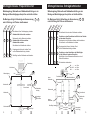
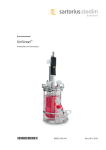
BEDIENUNGSANLEITUNG
Aufstellungshinweise
Montagehinweise
Talweg 12
·
D-75433 Maulbronn
Telefon: 07043 / 101-0 · Telefax: 07043/101-444
Fax International:
· ++ 49 7043/101-555
[email protected] · www.flux-pumpen.de
Copyright by FLUX-GERÄTE GMBH - Technische Änderungen vorbehalten - Printed in Germany - 954 60 610 23.07.02
Mischer
OPERATING INSTRUCTIONS
Installation Instructions
Mounting Instructions
Mixers/Agitators
Typ
FR..
Page 6 - 9
Type
FR..
Drehstrommotoren
Die Mischer werden aus Transportgründen in
Einzelkomponenten geliefert und müssen
am Einsatzort montiert werden.
Beachten Sie die Montagehinweise auf Seite 4 und 5.
Sicherheitshinweise
Mit Installationsarbeiten an Drehstrommotoren dürfen nur
Fachkräfte beauftragt werden.
Drehstrommotoren nur mit vorgeschaltetem
Motorschutzschalter in Betrieb nehmen.
Die Betriebsspannung mit dem Typenschild vergleichen.
Die Mischer sind nicht zum Mischen brennbarer
Flüssigkeiten der Gefahrklasse AI, AII und B zugelassen.
Mischer nur für bestimmungsgemäßen Gebrauch einsetzen.
Mischer so aufstellen, daß er nicht
in den Behälter fallen kann.
Betriebsinterne Anweisung beachten.
Schutzkleidung tragen
(Gesichtsschutz, Schutzhandschuhe usw. ).
Bedienungsanleitung des Motors beachten
( Bei Drehstrommotoren Sicherheitshinweis im Klemmkasten ).
Den Mischer nicht der Witterung aussetzen.
Den Mischer nicht über aggressiven Dämpfen
aufbewahren.
Drehrichtung des Motors prüfen.
Bei ortsbeweglichem Einsatz Drehrichtung erneut überprüfen
Drehrichtung gemäß Drehrichtungspfeil am Motor
(Siehe auch Montagehinweise auf Seite 4 und 5).
Aufstellungshinweise
Um das Rotieren des Rührguts in einem zylindrischen
Behälter zu verhindern, müssen mindestens
2 Stromstörer in das Behältnis eingebaut werden.
Auch eine außermittige Anordnung des Mischers
ist möglicherweise ausreichend.
Die Umfangsgeschwindigkeit der Mischflügel sollte
bei einem Propellermischer 2-15 m/s betragen,
bei einem Schrägblattmischer 4-10 m/s.
Stromstörer
Mischer erst einschalten, wenn der Mischflügel in die
Flüssigkeit eingetaucht ist.
2
Propellermischer :
d2 ~ ( 0,2 bis 0,4 ) x d1
h2 ~ ( 1 bis 1,5 ) x d2
b2 ~ 0,1 x d1
b3 ~ 0,02 x d1
d2
h2
b2
b3
Schrägblattmischer :
d2 ~ ( 0,3 bis 0,4 ) x d1
h2 ~ ( 0,5 bis 1 ) x d2
b2 ~ 0,1 x d1
b3 ~ 0,02 x d1
Außendurchmesser des Mischers
Bodenabstand des Mischers
Breite des Stromstörers
Behälterwandabstand des Stromstörers
Die angeführten Maße sind Erfahrungswerte, die sich bei ausgeführten
Modellversuchen als zweckmäßig ergeben haben
(Nach DIN 28 131, Sep 1992).
3
Montagehinweise Propellermischer
Montagehinweise Schrägblattmischer
Wellenkupplung, Motorwelle und Radialwellendichtring vor der
Montage auf Beschädigungen überprüfen und leicht einfetten.
Wellenkupplung, Motorwelle und Radialwellendichtring vor der
Montage auf Beschädigungen überprüfen und leicht einfetten.
Die Montage erfolgt in Reihenfolge der Nummerierung 1 ... 4
und in Richtung der Pfeile an den Nummern.
Die Montage erfolgt in Reihenfolge der Nummerierung 1 ... 5
und in Richtung der Pfeile an den Nummern.
Va
ria
e
nt
I
Va
ria
e
nt
II
Va
2
2
4
Va
ri
t
an
eI
Va
ria
e
nt
II
Va
ri
t
an
4
eI
II
Va
2
Mischerwelle auf die Motorwelle schieben.
Gewindestifte auf Nut ausrichten.
Gewindestifte anziehen.
Schutzflansch an Motorflansch schieben.
4
2
4
IV
3
Kupplungsschutzhülse mit leichtem Druck
an den Radialwellendichtring schieben.
4
4
Passfeder vor dem Aufschieben des Mischflügels
auf die Welle auf korrekten Sitz prüfen.
Mischflügel auf das Wellenende aufschieben und mit
Mutter festschrauben.
5
5
Schutzdeckel einschrauben.
Mischflügel auf das Wellenende aufschrauben.
Drehrichtung
te
Passfeder vor dem Einschieben der Welle in das Getriebe
auf korrekten Sitz prüfen.
Mischerwelle in das Getriebe schieben und festschrauben.
Schutzflansch an Getriebeflansch schieben.
2
2
n
ria
Schutzflansch über das obere Wellenende schieben.
1
Kupplungsschutzhülse mit leichtem Druck
an den Radialwellendichtring schieben.
3
4
III
Schutzflansch über Wellenkupplung schieben.
Gewindestifte dürfen nicht vorstehen.
1
2
ria
e
nt
M8 ............... ca. 15 Nm
M10; M12 .... ca. 20 Nm
M16 ............. ca. 30 Nm
Motorflansch
2
Nut
Wellenkupplung
Nut
Drehrichtung
oberes
Wellenende
1
2
Getriebeflansch
Passfeder
Gewindestifte
1
Schutzflansch
Radialwellendichtring
Mischerwelle
Schutzflansch
Mischerwelle
3
Kupplungsschutzhülse
Passfeder
Radialwellendichtring
Kupplungsschutzhülse
unteres
Wellenende
3
4
Mischflügel
Wellenende M 16
4
4
I
II
Mutter M16
ca. 60 Nm
Mischflügel
III
I
II
III
5
Schutzdeckel
(mit O-Ring)
IV
5
Three-phase Motors
For transport reasons the mixers are supplied
as individual component parts which have to
be assembled before starting operation.
Please refer to mounting instructions on page 8 and 9.
Installation of three-phase motors should only be carried out
by suitably qualified personnel only.
Only use three-phase motors with a starter including an
overload cut-out.
Make sure that the supply voltage corresponds to the voltage
Safety Instructions
indicated on the name plate.
Check direction of rotation of the motor.
In case of protable use, check direction of rotation before each
operation. Direction of rotation according to the arrow on the motor.
The mixers/agitators are not approved for use with
flammable liquids class AI, AII and B.
Only use the mixer/agitator for its intended purpose.
Install the mixer/agitator in a way that ensures that it
cannot fall into the container.
( Please refer to mounting instructions on page 8 and 9 ).
Installation Instructions
To prevent the liquid from rotating within a cylidrical
container, at least 2 baffles have to be installed
in the container.
Comply with all relevant safety instructions.
Wear appropriate protective clothing.
(Face shield, protective gloves, etc. ).
An off-centered installation of the mixer/agitator may
also be sufficient.
Comply with the operating instructions of the motor.
The velocity of the mixing blade should be:
propeller type:
2-15 m/sec.
skew blade type:
4-10 m/sec.
( Some three-phase motors have their safety instructions contained with
the terminal box ).
The mixer/agitator should not be exposed to the weather.
Never store the mixer/agitator in areas in which corrosive
vapours exist.
Never start the mixer/agitator unless the mixing blade
has been immersed into the liquid.
Baffle
Propeller type :
d2 ~ ( 0,2 to 0,4 ) x d1
h2 ~ ( 1 to 1,5 ) x d2
b2 ~ 0,1 x d1
b3 ~ 0,02 x d1
d2
h2
b2
b3
Skew blade type :
d2 ~ ( 0,3 to 0,4 ) x d1
h2 ~ ( 0,5 to 1 ) x d2
b2 ~ 0,1 x d1
b3 ~ 0,02 x d1
outer diameter of mixer
distance to bottom of container
width of baffle
distance to container wall of baffle
The above values are experimental values which prooved to be useful
during test runs. (According to DIN 28 131, Sep 1992).
6
7
Mounting Instructions Propeller Type
Mounting Instructions Skew Blade Type
Check shaft coupling, motor shaft and radial shaft seal for damage
and slightly grease these parts before mounting.
Check shaft coupling, motor shaft and radial shaft seal for damage
and slightly grease these parts before mounting.
Mounting sequence according to the numbering 1 ... 4
in the direction of the arrows assigned to the numbers.
Mounting sequence according to the numbering 1 ... 5
in the direction of the arrows assigned to the numbers.
Va
ria
nt
I
Va
ria
II
nt
Va
4
2
III
Va
2
I
Va
ria
II
nt
Va
ria
nt
Apply slight force to push protective sleeve
next to the radial shaft seal.
4
Screw mixing blade onto the shaft end.
III
Va
2
4
2
4
Direction of
rotation
IV
Check adjusting spring for correct seat, before inserting
the mixing shaft into the gear.
Insert mixing shaft into the gear and firmly tighten it.
Push protective flange until it touches the gear flange.
2
2
ri
t
an
Slide protective flange onto the upper mixing shaft end.
1
Slide mixing shaft onto the motor shaft.
Align threaded pins to the grooves.
Thighten threaded pins.
Push protective flange until it touches the motor flange.
3
4
ria
nt
Slide protective flange onto the shaft coupling.
Make sure that the threaded pins do not jut out.
1
2
ria
nt
3
Apply slight force to push protective sleeve next to the
radial seal.
4
4
Check adjusting spring for correct seat, before sliding on
the mixing blade.
Slide mixing blade onto the lower shaft end and fasten it
by the nut.
5
5
Screw on the protective cover.
M8 ............... approx. 15 Nm
M10; M12 .... approx. 20 Nm
M16 ............. approx. 30 Nm
Motor flange
Shaft coupling
2
Groove
Groove
Direction of
rotation
upper mixing
shaft end
1
Threaded
pins
2
Gear flange
Adjusting
spring
Protective
flange
Radial shaft
seal
1
Mixing shaft
Protective
flange
Mixing shaft
3
Adjusting
springr
lower mixing
shaft end
Protective
sleeve for
coupling
4
I
II
Nut M16
approx. 60 Nm
Mixing blade
III
3
Radial shaft
seal
4
Mixing blade
Shaft end M 16
8
Protective
sleeve for
coupling
I
II
III
5
Protective cover
(with O-Ring)
IV
9