1
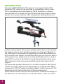
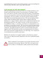
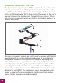
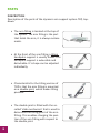
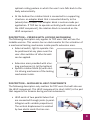
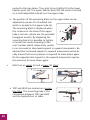
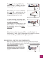
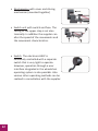
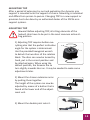
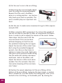
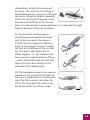
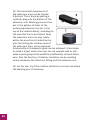
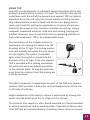
TOP
DYNAMIC ARM SUPPORT SYSTEM
User's manual
Contents
INTRODUCTION
page 2
FOR WHOM IS TOP INTENDED
page 3
WORKING PRINCIPLE
page 4
PARTS
page 6
DESCRIPTION
page 6
DESCRIPTION - MECHANICAL HELP COMPONENTS
page 9
DESCRIPTION - ELECTRICAL HELP COMPONENTS
page 11
MOUNTING
page 13
ADJUSTING
page 13
USE
page 17
WARNING
page 19
MAINTENANCE
page 19
CE MARK
page 19
WARRANTY
page 20
CONTACTINFORMATION
page 24
V.10.07
1
INTRODUCTION
This is the USER’S MANUAL of the dynamic arm support system TOP
(hereafter TOP), which can be mounted on a wheelchair, chair or table.
TOP is manufactured and distributed by FOCAL Meditech, a company
that specializes in the supply of high-end head and body support systems,
dynamic arm support systems, robot manipulators, feeding devices and
custom-made products. This manual provides information on the product,
the purpose, how to use it and the consequences of using it. The goal of
this information is to guarantee a longlasting, successful and effective use
of the dynamic arm support. You will know what you can and can't expect
of the dynamic arm support and it provides global information on how to
adjust TOP as well as to what features need special attention when using
TOP. In the back of the manual you will find contact information of the
supplier.
This manual also provides information on our HELP component. HELP (which,
in Dutch, is short for ‘High And Low Positioning’) is a usually standard added
component to TOP that makes it possible to support vertical movements. This
information is only important for users of this extra component.
Please take the time to read this information well: Profound knowledge of
this aid leads to a more efficient use and yields better results. It is recom-
2
mended that this manual is also read by persons in your surroundings, for
instance those that play a role in your day-to-day care!
FOR WHOM IS TOP INTENDED?
TOP was developed for all persons that can no longer position or use
forearm and hand due to lack of muscle power or neulogical facilities. To be able to use TOP, at least some functionality in shoulderbelt
and arm are required as well as some functionality of the hand (grab,
manipulate). The arm support can also be used by healthy persons
that often have burdening (job) positions. TOP can be deployed both
single-sided and double-sided. Single-sided or double-sided use
depends on a range of factors, like the user's individual limitations and
possibilities and his or her needs. The user of TOP can be active in a
lot of different areas, i.e. at home, at school or in a job location, in an
institution or any other location. TOP can also be used therapeutically,
for instance by letting the user work with an increasing reach or with
resistance. The HELP component, which is almost always delivered
together with TOP, facilitates vertical arm displacements that allow a
user to eat and drink independently or to reach high. This component
is considered to be useful for most users.
Whether the dynamic arm support system is mounted on a wheelchair, chair or table also partly depends on the user's individual needs
and wishes.
When reading the manual please pay special attention to the
instructions concerning 'safe use'. Text that is of special interest for safety is marked with a safety symbol (see example).
3
WORKING PRINCIPLE OF TOP
The dynamic arm support system TOP is a system of axes with several
rotation points, with an arm fitting and a connection with the 'real'
world (chair, wheelchair, table or movable carriage). The forearm rests
in the arm fitting allowing TOP to bear most of the weight of the user's
arm and relieving the shoulder belt. Through the axes system TOP can
aid conveying movements which are initiated in shoulders and arm, to
forearm and hands.
Dynamic arm support systems are mostly used by persons with limited
muscle strength in shoulder belt or arms because of neurological or
orthopaedic diseases in these parts of the body. By deploying what
is left of the user's own capacities he or she can bring the hands to a
'useful' position. Reaching, grabbing and manipulating and therefore
executing all kinds of daily activities are possible again. TOP operates
horizontally and is not extra powered. The HELP component is usually
delivered as part of TOP. This component, which is supported mechanically by means of a spring mechanism, facilitates vertical displacements. Electric empowering can be supplied.
4
TOP is characterized by a very rigid construction with high-quality
bearings and with a minimal tolerance in the different axes. It operates extremely light and smooth. This light operation together with a
perfect fit and extensive adjustability demands little use of force by
the user. TOP has more rotation points and more motion axes - even
vertically - than any other known product. This makes its movements
light and smooth. The system 'follows' the user's arm perfectly and the
arm doesn't 'lock-up'. TOP is highly customisable and individual adjustments are made when needed.
Version with locking mechanism
For users who are in need of a system that can be fixed in any given
position a lockable version is available. Users can independently operate this function. The following are examples of situations where
locking sometimes is desired: outdoor wheelchair driving; use during
transfers.
Locking is performed by the use of a switch. This switch operates a
an electric locking mechanism. Locking takes place in horizontal plane
and can be realised in any given position. The locking mechanism is an
optional feature and can be supplied for mechanical as well as electrically powered versions.
5
PARTS
DESCRIPTION
Description of the parts of the dynamic arm support system TOP, topdown.
•The arm fitting is located at the top of
the system. The arm fitting is the part
that holds the arm, it is always custommade.
•At the front of the arm fitting a tilting
handpalm support is usually found. This
handpalm support is extensible and
detachable. It's shape can be adjusted
individually.
•Characteristic for the tilting version of
TOP is that the arm fitting is mounted
on a double joint, which makes tilting
possible.
•The double joint is fitted with the socalled 'slide mechanism' that is used to
determine the tilting point of the arm
fitting. This enables changing the position of the arm fitting with respect to
the double joint.
6
•The double joint is combined with the carriers of the beforementioned handpalm support and the automatic elbow support.
•The purpose of the automatic elbow
support is to prevent the forearm
from sliding out of the arm fitting
when this is tilted upwards. The automatic elbow support can also be used
to limit the tilting angle of the forearm.
•The so-called 'direct connecting rod'
is located under the double joint.
The direct connecting rod is a metal
b
shaft that is mounted in the bearings
a
of the extension arm below it. The
direct connecting rod allows the arm
fitting to rotate over the extension arm. A short (a) and a long
(b) version of the direct connecting rod exist. When the short
version is used, the arm fitting can rotate directly above the
extension arm. When tilted the arm fitting could collide with the
extension arm. When the long version is used this collision is
prevented over a long tilting distance.
•Together with the arm fitting the extension arms provide the
actual horizontal support of the forearm. The base version exists
of two short extension arms and
one long one, which are respectively
70mm and 120mm long, but this can
be changed according to the wishes
of the user in order to create a maxi-
7
mum reach. All joints of the extension arms exist of shafts and
bearings as described directly above.
•The rotation of the extension arms can
be limited by means of a synthetic plug.
This plug is put into the bottom of the
extension arm. Also, one or two blocking pins can be fitted in small holes
which are located in the top of the
extension arm below.
•The lower extension arm runs into the rotation block. The rotation block is a construction that exists of
two circular discs that can be rotated in
respect to each other. At the top it has
bearings in which the extension arm
above is fitted.
•Around the center hole there's a pattern of smaller holes that allow limitation of rotation. The angle under which
the upper components (for horizontal
movement) operate can be adjusted
by means of the rotation block. This
is done by changing the angle under
which the arm support operates. This
change can be made by turning the
two discs - that have sloped edges in respect to each other. Note: when
adjusting the angle one should choose
between the device's assistance in a
certain direction of movement and an
8
optimal resting posture in which the user's arm falls back to the
body automatically.
•At the bottom the rotation block is connected to a supporting
structure: an adapter block that is mounted directly to the
(wheel)chair or table. This adapter block is custom-made per
application. If TOP has to operate vertically (with assistance of
the HELP component), the rotation block is mounted on the
HELP component.
DESCRIPTION – VERSION WITH LOCKING MECHANISM
The following description only applies to TOP users that will use the
lockable version. This version has an electromotor for the activation of
a mechanical locking mechanism inside specific extension arms.
•External switch, light to operate. Can
be positioned at any place near the
user. Also switches of other brands
can be applied.
•Extension arms provided with a locking mechanism (a) (at the bottom)
•Specific rotation block (b) with electric driving mechansim of the locking
mechanism inside.
a
b
DESCRIPTION – MECHANICAL HELP COMPONENTS
The following description only matters for TOP users that will also use
the HELP component. This HELP component (in short: HELP) is the part
that supports the forearm during vertical movements.
•HELP exists of two parallel tubes that
are connected through joints (a parallellogram with variable proportions).
The vertical displacement is assisted
by two elastic cords that are con-
c
a
b
9
nected to the two tubes. The cords (a) are tightly fit to the lower
fixation point (b). The upper fixation point for the cords is located
on a small adjustable block(c) on the upper tube.
•The position of the mounting block on the upper tube can be
adjusted by means of a threaded rod
which is located in the upper tube (a).
The mounting block is displaced when
a
the screw ax at the back of the upper
tube is turned - please use the provided
hexagonal wrench. By displacing the
mounting block it is possible to tighten
or loosen the cords according to the
user's wishes which respectively results
in an increased or decreased support in upward movements. Be
advised that increased support in upward movements automatically means that more pressure is required to move down again.
On the opposite less support in the upward movement requires
less pressure to move down again.
•
HELP has an upper (a) and a lower (b) 'stop'.
a
b
•TOP and HELP are located on a mounting tube. The mounting tube is the
connection between TOP and HELP
and the (wheel)chair or table.
10
•The lever for blocking HELP in the
lower position is located at the front
of the mounting tube. Mechanical
version only.
•This blocking mechanism is effected
by a hook that is positioned over the
lower tube. The lever enables attaching and detaching the hook.
•To make operation of the lever easy
and to prevent obstruction, the lever
is made telescopically.
The position of the upper part of the
lever - when it is not extended - can
be adjusted by means of an adjustment ring (a).
a
•Below the mounting tube you will find a specific adapter for
mounting on a table, chair or wheelchair. This adapter is custommade and offers possibilities for height adjustment.
DESCRIPTION – ELECTRIC HELP COMPONENTS
•If the up and down movements cannot be performed adequately, the HELP component can be fitted with electrically powered
vertical displacement. An electromotor with accessories is fitted at
the back of HELP. This electromotor
is usually operated with a separate
switch.
11
•Electromotor with cover and driving
mechanism (mounted together)
•Switch unit with switch and fuse. The
tuning of the upper stop is set electronically. In addition the supplier can
alter the speed of the movements and
the movement characteristics.
•Switch. The electronic HELP is
commonly controlled with a separate
switch that is very light to operate.
However, operation through a user
interface integrated in the wheelchair
operating system is also possible. Also
various other operating methods can be
realised in consultation with the supplier.
12
MOUNTING TOP
After a period of extensive try-out and evaluation the dynamic arm
support is mounted onto the support of choice. Mounting is individual
and differs form person to person. Changing TOP to a new support or
provision has to be done by an authorized dealer of the FOCAL arm
support systems.
ADJUSTING TOP
Beware! Before adjusting TOP, all sitting elements of the
(wheel) chair have to be put in the most common active sitting position.
1) Adjusting TOP requires before everything else that the perfect inclination
angle for the system is determined.
Use the provided hexagonal wrench
to detach the two discs of the rotation
block. The discs can now be turned by
hand, put in the correct position and
be attached again. When using the
default position, the forearm has to
turn slightly inwards later on. It may be needed to make some
adjustments later.
2) Mount the chosen extension arms
by putting them together.
The height of the system can now be
adjusted by means of a button that is
found at the lower end of the adjustment unit.
3) Mount the double-joint onto it.
13
4) Put the user's arm in the arm fitting.
5) Determing the correct heigth adjustment by using the mounting adapter.
Beware that the user's shoulders when in a resting position - are horizontally lined up as much as possible. The
user's comfort plays an important role
here!
6) Ask the user to make some movements to get a little acquainted with TOP.
7) When using the HELP component: Try to level the weight of
the arm as much as possible in order to compensate the downforce. In order to do so adjust the tension of the cords. Follow
these steps: Ask the user to lift the
arm and check if this can be done
without dropping or that the user
has problems lowering the arm again.
Adjust the tension of the cords if needed: using the provided hexagonal
wrench, turn the ax a few times to
tighten or loosen the cords. Right rotation gives more assistance when lifting
the arm while left rotation decreases
assistance. Look at the effect, and
adjust the tension a little more when
needed. Turn the ax back a few rotations when lowering of the arm becomes 'heavy' .
8) Position the swivel adjustment of the arm fitting. At the
bottom of the arm fitting - between the two screws - a sunken
bolt is located (a). This bolt fixates the sliding plate, that is connected to the arm fitting, to the double joint. By moving the
14
sliding plate, tilting the forearm will
a
be easier. The more the arm fitting is
moved backwards in respect to the joint
the easier tilting the forearm upwards
will be. At some point however it will
become more difficult to tilt the arm
back. It is advised that a good adjustment is made with the right
balance between tilting up and down.
9) The automatic elbow support
should be pressed against the lower
part of the arm when the forearm
is tilted. Further adjust the effective
angle of the support cushion through
the bolt at the bottom of the cushion
(a). The depth adjustment of the
elbow support - i.e. the distance between support cushion and arm fitting
- can be altered through the bolt that
fixates the little bent rod (b) in the
backside of the double joint.
a
b
10) The handpalm support can now be
moved in such a way that the palm of
the hand is supported in a comfortable
way. The little cushion can either be
left to tilt along with the hand or can
be fixated under any chosen angle.
15
11) The horizontal movements of
the extension arms can be limited
if desired. This is done by putting a
synthetic plug into the bottom of the
extension arm. Blocking pins are then
put in the pattern of holes of the
underlying extension arm (or in the
top of the rotation block), according to
the area that has to be limited. Now,
the extension arms can only rotate
within the area that is limited by the
pins. By limiting the rotation area of
the extension arms, some improved
functionality or therapeutic goals can be achieved. It also helps
to avoid a traject where the user can not operate well or activates muscle groups that would be insufficiently strained otherwise. Also the function of rotation limitation can be avoiding
contact between the tilted arm fitting and the extension arm.
12) Let the user try if the rotation limitation is correct and adjust
the blocking pins if necessary.
16
USING TOP
How TOP is used depends on individual needs and wishes of the user
and by the environment in which it is used. The activities that can be
undertaken with the aid of the dynamic arm support TOP are almost
unlimited. Every Day Life activities consist mainly of eating and drinking independently as well as facial and dental care. Being able to
reach one's head for putting on spectacles or a hearing aid are considered to be important too. Common activities are writing, using a
computer, household activities, child care and nursing, playing and
hobbies. However, even in such futile tasks as operating switches or
daily used equipment, TOP is an indispensable asset.
The mechanism of the lockable version is
switched on by moving the switch into the
direction of the ‘X’ sign. The locking mechanism will actually lock when the user moves
his arm slightly. The system is unlocked
again when the switch is moved into the
direction of the ‘O’ sign. If the arm support
TOP is provided with a locking mechanism
the extension arms are default connected
to the rotation block. To take the extension
arms from the rotation block the locking pin
must be removed.
The HELP component is integrated into most of the TOP arm support
systems. HELP provides a means for vertical displacements of the arm
in all kinds of activities.
Height adaptation of the electric version is performed by moving the
switch into the direction of the ‘H’ (High) or the ‘L’(Low).
The dynamic arm support is often found mounted on a hand-operated
or electric wheelchair and on working chairs. Especially in labour situations TOP will be mounted directly to working tables. Users are known
17
to change their transport and sitting devices often. Of course it is possible to mount a dynamic arm support on every device a user has. To
serve efficiency, the part that facilitates vertical displacement can be
made interchangeable if this is technically and functionally possible.
When the proper adjustments have been made the actual use is very
simple.
The arm fitting can be provided with special accessories to allow the
user to perform specific tasks like writing or eating. The dynamic arm
support can also be used in combination with special hand splints.
18
WARNING
1) Never unlock the HELP component when not pressed
upon, i.e. without an arm in it. If done so, the arm support
will jump upwards and can harm persons or damage
objects. When, for example in case of maintenance, HELP has to be
unlocked without the user's arm in it, please make sure to fixate the
moving part with your hand.
2) The arm support may never be used as support to lean on
or to get upright. During evaluation it should be accounted
for that the user sits stable and that it is possible for him or
her to come into an upright position without leaning on the arm support.
MAINTENANCE
Not much maintenance is required for this dynamic arm support. The
device can be cleaned with a moist cloth and a non-aggressive cleaning agent. Strong heating of the arm fitting, for instance by putting it
on a central heating or in direct sunlight, should be avoided.
CE MARK
This product was CE approved and complies with European
regulations for medical aids.
19
WARRANTY
GENERAL
These guarantees are part of the General Conditions of FOCAL
Meditech. In the Warranty, the provisions in the General Conditions
are to be respected.
The following warranty terms are based on EU Directive 99/44/EC and
the Dutch Civil Code. The marketing and use of medical devices are
also specified in Directive 93/42/EEC and Royal Order 243 of March
30th, 1995. The resulting rights remain unaffected, as well as the warranty from the dealer to the end user.
Warranty Terms and Conditions may be extended or modified if they
are in writing and in compliance with the law.
Our products are produced and assembled with the utmost care.
However, certain product defects can occur. At request, FOCAL
Meditech will repair all defects, both inside and outside, during the
warranty period. This guarantees that the product life span is not
negatively affected.
WARRANTY PROVISIONS
The warranty for this product is according to the following conditions:
Article 1
We will rectify, free of charge and subject to the conditions 2 to 14,
all product defects that are manifest within 24 months from the date
of delivery to the end user. In the case of professional or equivalent
usage, the guarantee is limited to 12 months. The guarantee for used
products is also limited to a period of 12 months.
Article 2
Our guarantee means that the product will be returned in the same
condition it was in before the defect occurred. FOCAL Meditech decides whether defective parts are repaired or replaced. Parts that are
replaced without charge will become our property.
20
Article 3
The defect must be reported immediately to prevent possible further
damage. The warranty is void if the defect is NOT reported within two
months after determining the defect.
Article 4
To invoke the warranty, the personalized sales receipt or proof of
delivery or purchase must be submitted. In case these are not available, other convincing evidence should be submitted.
Article 5
The warranty does NOT cover small deviations from the prescribed
quality, such as, but not exclusively, deviations in measurement or size
which are insignificant for the value, suitability or functionality of the
product.
Article 6
The warranty does not cover damage caused by improper or incondiderate use or use for other uses than the product was designed for.
Article 7
The warranty does not apply when damage is caused by:
1)Chemical and electro-chemical influence of water or other
liquids.
2)Abnormal environmental conditions in general.
3)Operating conditions which are unsuitable for the product, e.g.
unusual pressures and accelerations.
4)Contact with aggressive substances.
5)Neglect.
6)Any other external cause from outside, for instance bumping or
collision.
Article 8
Warranty does NOT cover malfunction because of damage sustained
during transport and beyond the responsibility of FOCAL Meditech,
21
installation or assembly by non-qualified persons, poor or inadequate
maintenance, or ignoring the instructions.
Article 9
Warranty is void if the defect was caused by repair or interventions by
third parties that are not qualified or skilled, or if the product is fitted
with accessories or parts that are not original. The warranty also expires if marks or serial numbers have been removed.
Article 10
Repair on site within 14 days will be pursued. However repair on site
can only be required in the case of a minor problem, to be determined
by the supplier. Transportation of the device to a workplace or the
manufacturer may be required.
Article 11
If, during the warranty period, repair of the same defect fails repeatedly or the repair costs are disproportionate, an equivalent replacement
is provided in consultation with the user. In case of replacement, we
reserve the right to charge a fee in accordance with the elapsed time
of use.
Article 12
Repair under warranty does not extend the guarantee or warranty or
the start of a new period except for the part of the product that was
repaired. FOCAL Meditech provides a warranty period of 12 months,
limited to the particular defect.
Article 13
Necessary or desirable adjustments are not part of the standard product, as documented in the manual. FOCAL Meditech will try to deal
with failures of individual adjustments in accordance with the provisions of the standard product warranty. Necessary or desirable individual adjustments do not form part of the warranty.
22
Article 14
Claims of the purchaser under a warranty are not transferable to third
parties.
This warranty covers products that are bought and / or in-service in
the Netherlands. If a product is marketed abroad, the user must check
whether the conditions there (e.g. voltage, climatic conditions) are in
accordance with the established operating conditions. In the case of
resale, the reseller should provide guarantee.
FOCAL Meditech attaches great importance to the functioning of its
products, which tend to serve persons with significant limitations.
Consultation about defects or malfunction of the product due to factors not described in the warranty is highly recommended.
The service facilities of FOCAL Meditech are always available to the
user, even when the warranty has expired.
23
CONTACT INFORMATION
The dynamic arm support TOP and the HELP component are
manufactured by
FOCAL Meditech BV
Droogdokkeneiland 19
5026 SP Tilburg
The Netherlands.
Phone:
+31 (0)13 533 31 03
Fax:
+31 (0)13 533 50 04
E-mail:
[email protected]
Internet: www.focalmeditech.nl
The dynamic arm support TOP and the HELP component are
delivered by
24
FOCAL Meditech BV
Droogdokkeneiland 19
5026 SP Tilburg
Nederland
T
+31 (0)13 533 31 03
F
+31 (0)13 533 50 04
E
[email protected]
I
www.focalmeditech.nl